EP0224156A2 - Hydraulic system with a hydraulic motor and a pressure-operated valve - Google Patents
Hydraulic system with a hydraulic motor and a pressure-operated valve Download PDFInfo
- Publication number
- EP0224156A2 EP0224156A2 EP86115882A EP86115882A EP0224156A2 EP 0224156 A2 EP0224156 A2 EP 0224156A2 EP 86115882 A EP86115882 A EP 86115882A EP 86115882 A EP86115882 A EP 86115882A EP 0224156 A2 EP0224156 A2 EP 0224156A2
- Authority
- EP
- European Patent Office
- Prior art keywords
- pressure
- valve
- outlet
- inlet
- line
- Prior art date
- Legal status (The legal status is an assumption and is not a legal conclusion. Google has not performed a legal analysis and makes no representation as to the accuracy of the status listed.)
- Withdrawn
Links
- 230000007423 decrease Effects 0.000 description 5
- 239000010687 lubricating oil Substances 0.000 description 3
- 239000012530 fluid Substances 0.000 description 2
- 239000007788 liquid Substances 0.000 description 2
- 230000007935 neutral effect Effects 0.000 description 2
- 230000001105 regulatory effect Effects 0.000 description 2
- 238000013459 approach Methods 0.000 description 1
- 230000007257 malfunction Effects 0.000 description 1
- 239000003921 oil Substances 0.000 description 1
Images

Classifications
-
- F—MECHANICAL ENGINEERING; LIGHTING; HEATING; WEAPONS; BLASTING
- F15—FLUID-PRESSURE ACTUATORS; HYDRAULICS OR PNEUMATICS IN GENERAL
- F15B—SYSTEMS ACTING BY MEANS OF FLUIDS IN GENERAL; FLUID-PRESSURE ACTUATORS, e.g. SERVOMOTORS; DETAILS OF FLUID-PRESSURE SYSTEMS, NOT OTHERWISE PROVIDED FOR
- F15B11/00—Servomotor systems without provision for follow-up action; Circuits therefor
- F15B11/02—Systems essentially incorporating special features for controlling the speed or actuating force of an output member
-
- F—MECHANICAL ENGINEERING; LIGHTING; HEATING; WEAPONS; BLASTING
- F15—FLUID-PRESSURE ACTUATORS; HYDRAULICS OR PNEUMATICS IN GENERAL
- F15B—SYSTEMS ACTING BY MEANS OF FLUIDS IN GENERAL; FLUID-PRESSURE ACTUATORS, e.g. SERVOMOTORS; DETAILS OF FLUID-PRESSURE SYSTEMS, NOT OTHERWISE PROVIDED FOR
- F15B2211/00—Circuits for servomotor systems
- F15B2211/20—Fluid pressure source, e.g. accumulator or variable axial piston pump
- F15B2211/205—Systems with pumps
- F15B2211/2053—Type of pump
- F15B2211/20538—Type of pump constant capacity
-
- F—MECHANICAL ENGINEERING; LIGHTING; HEATING; WEAPONS; BLASTING
- F15—FLUID-PRESSURE ACTUATORS; HYDRAULICS OR PNEUMATICS IN GENERAL
- F15B—SYSTEMS ACTING BY MEANS OF FLUIDS IN GENERAL; FLUID-PRESSURE ACTUATORS, e.g. SERVOMOTORS; DETAILS OF FLUID-PRESSURE SYSTEMS, NOT OTHERWISE PROVIDED FOR
- F15B2211/00—Circuits for servomotor systems
- F15B2211/30—Directional control
- F15B2211/305—Directional control characterised by the type of valves
- F15B2211/30505—Non-return valves, i.e. check valves
-
- F—MECHANICAL ENGINEERING; LIGHTING; HEATING; WEAPONS; BLASTING
- F15—FLUID-PRESSURE ACTUATORS; HYDRAULICS OR PNEUMATICS IN GENERAL
- F15B—SYSTEMS ACTING BY MEANS OF FLUIDS IN GENERAL; FLUID-PRESSURE ACTUATORS, e.g. SERVOMOTORS; DETAILS OF FLUID-PRESSURE SYSTEMS, NOT OTHERWISE PROVIDED FOR
- F15B2211/00—Circuits for servomotor systems
- F15B2211/30—Directional control
- F15B2211/31—Directional control characterised by the positions of the valve element
- F15B2211/3105—Neutral or centre positions
- F15B2211/3111—Neutral or centre positions the pump port being closed in the centre position, e.g. so-called closed centre
-
- F—MECHANICAL ENGINEERING; LIGHTING; HEATING; WEAPONS; BLASTING
- F15—FLUID-PRESSURE ACTUATORS; HYDRAULICS OR PNEUMATICS IN GENERAL
- F15B—SYSTEMS ACTING BY MEANS OF FLUIDS IN GENERAL; FLUID-PRESSURE ACTUATORS, e.g. SERVOMOTORS; DETAILS OF FLUID-PRESSURE SYSTEMS, NOT OTHERWISE PROVIDED FOR
- F15B2211/00—Circuits for servomotor systems
- F15B2211/30—Directional control
- F15B2211/31—Directional control characterised by the positions of the valve element
- F15B2211/3122—Special positions other than the pump port being connected to working ports or the working ports being connected to the return line
- F15B2211/3127—Floating position connecting the working ports and the return line
-
- F—MECHANICAL ENGINEERING; LIGHTING; HEATING; WEAPONS; BLASTING
- F15—FLUID-PRESSURE ACTUATORS; HYDRAULICS OR PNEUMATICS IN GENERAL
- F15B—SYSTEMS ACTING BY MEANS OF FLUIDS IN GENERAL; FLUID-PRESSURE ACTUATORS, e.g. SERVOMOTORS; DETAILS OF FLUID-PRESSURE SYSTEMS, NOT OTHERWISE PROVIDED FOR
- F15B2211/00—Circuits for servomotor systems
- F15B2211/30—Directional control
- F15B2211/31—Directional control characterised by the positions of the valve element
- F15B2211/3144—Directional control characterised by the positions of the valve element the positions being continuously variable, e.g. as realised by proportional valves
-
- F—MECHANICAL ENGINEERING; LIGHTING; HEATING; WEAPONS; BLASTING
- F15—FLUID-PRESSURE ACTUATORS; HYDRAULICS OR PNEUMATICS IN GENERAL
- F15B—SYSTEMS ACTING BY MEANS OF FLUIDS IN GENERAL; FLUID-PRESSURE ACTUATORS, e.g. SERVOMOTORS; DETAILS OF FLUID-PRESSURE SYSTEMS, NOT OTHERWISE PROVIDED FOR
- F15B2211/00—Circuits for servomotor systems
- F15B2211/30—Directional control
- F15B2211/32—Directional control characterised by the type of actuation
- F15B2211/329—Directional control characterised by the type of actuation actuated by fluid pressure
-
- F—MECHANICAL ENGINEERING; LIGHTING; HEATING; WEAPONS; BLASTING
- F15—FLUID-PRESSURE ACTUATORS; HYDRAULICS OR PNEUMATICS IN GENERAL
- F15B—SYSTEMS ACTING BY MEANS OF FLUIDS IN GENERAL; FLUID-PRESSURE ACTUATORS, e.g. SERVOMOTORS; DETAILS OF FLUID-PRESSURE SYSTEMS, NOT OTHERWISE PROVIDED FOR
- F15B2211/00—Circuits for servomotor systems
- F15B2211/40—Flow control
- F15B2211/405—Flow control characterised by the type of flow control means or valve
- F15B2211/40515—Flow control characterised by the type of flow control means or valve with variable throttles or orifices
-
- F—MECHANICAL ENGINEERING; LIGHTING; HEATING; WEAPONS; BLASTING
- F15—FLUID-PRESSURE ACTUATORS; HYDRAULICS OR PNEUMATICS IN GENERAL
- F15B—SYSTEMS ACTING BY MEANS OF FLUIDS IN GENERAL; FLUID-PRESSURE ACTUATORS, e.g. SERVOMOTORS; DETAILS OF FLUID-PRESSURE SYSTEMS, NOT OTHERWISE PROVIDED FOR
- F15B2211/00—Circuits for servomotor systems
- F15B2211/40—Flow control
- F15B2211/415—Flow control characterised by the connections of the flow control means in the circuit
- F15B2211/41572—Flow control characterised by the connections of the flow control means in the circuit being connected to a pressure source and an output member
-
- F—MECHANICAL ENGINEERING; LIGHTING; HEATING; WEAPONS; BLASTING
- F15—FLUID-PRESSURE ACTUATORS; HYDRAULICS OR PNEUMATICS IN GENERAL
- F15B—SYSTEMS ACTING BY MEANS OF FLUIDS IN GENERAL; FLUID-PRESSURE ACTUATORS, e.g. SERVOMOTORS; DETAILS OF FLUID-PRESSURE SYSTEMS, NOT OTHERWISE PROVIDED FOR
- F15B2211/00—Circuits for servomotor systems
- F15B2211/70—Output members, e.g. hydraulic motors or cylinders or control therefor
- F15B2211/705—Output members, e.g. hydraulic motors or cylinders or control therefor characterised by the type of output members or actuators
- F15B2211/7058—Rotary output members
Definitions
- the invention relates to a hydraulic system with a hydraulic motor, the inlet of which is connected to a pressure source via a supply line and the outlet of which is connected to a return pressure source via a return line, and to a pressure-controlled valve which interrupts the supply line at a certain pressure in the return line.
- Hydraulic motors are typically lubricated internally by leakage of high pressure fluid, with precautions being taken to drain this flow of lubricating oil.
- One way to do this is to provide an additional return line.
- an additional return line is undesirable for cost and other reasons.
- Another possibility is that the lubricating oil return flow is fed to the return line leading from the engine outlet.
- the seals of the motor housing are damaged if there is excess pressure in the return line.
- the object to be achieved with the invention is seen in excluding damage to the hydraulic motor in the case of excess pressure in the return line.
- This object has been achieved according to the invention in that the pressure-controlled After the interruption of the supply line, the valve can be moved into a further position in which the inlet of the hydraulic motor is connected to the return pressure source. In this way, the inlet of a hydraulic motor is connected to a collecting tank, so that the pressure on the inlet side can also quickly decrease, which prevents damage to the seals of the housing due to excess pressure.
- the known hydraulic system in which the pressure-controlled valve has a valve bore into which an inlet which connects the valve bore to the pressure source and a second outlet which opens the valve bore to the inlet of the hydraulic motor open that a first outlet opens into the valve bore, which connects the valve bore to the return pressure source, and a third outlet, which connects the valve bore to the outlet of the engine via the pilot line connected to the return line, further in that the control slide of the pressure-controlled valve has three positions can take, wherein in the first position the inlet is connected to the second outlet and the third outlet is blocked and in the second position the first and second outlet are blocked and the inlet is connected to the third outlet, and in the third position the first and second outlet are connected to one another and the inlet is connected to the third outlet.
- a pressure will build up in the pilot line which initially shifts the pressure-controlled valve from its supply position to a position in which the supply to the hydraulic motor is interrupted, but in which the supply is connected by the pump via a secondary line to the pilot line, so that a pilot pressure can then build up, which immediately adjusts the valve to a third position in which the inlet of the engine is connected to the collecting container.
- the valve is held in this position as long as the pressure source pressurizes the pilot space of the valve. So that pressure can reach the return line from the pressure source in the third position of the pressure-controlled valve, the invention further provides that a check valve is installed in the pilot line.
- the supply to the hydraulic motor is controlled via a control valve which can generally be operated manually, and so that the pilot pressure can decrease
- the control valve can assume a position in which the inlet in the pressure-controlled valve and the Return line are connected to the return pressure source.
- a spring provided according to the invention can move the control slide of the pressure-controlled valve back into its first position, in which the inlet then again with the inlet side of the hydraulic motor is connected. After that, only the control spool needs to be moved back to its closed position and the hydraulic motor is fully operational again.
- the first outlet can expediently extend axially to the valve bore, namely from one end through the valve housing extending channel exist, the spring is supported at one end on the valve slide and the other end on a housing wall at one end of the valve bore.
- the pressure source is not connected to the pilot line, and in which the control spool only has to take two positions, the inlet being connected to the second outlet and a first outlet being blocked in the first position and in the second position the inlet is blocked and the first and second outlet are connected to each other and wherein the control slide is adjustable in its first position by means of a spring and in its second position by means of the pressure in a pilot line which is connected to the return line .
- a control valve 20 controls the connection between a pressure source 22 in the form of a pump, a return pressure source 24 in the form of a collecting container, the supply line 12 and the return line 14.
- the control valve 20 can assume three positions, namely a neutral position in which the flow to the supply line and the return flow from the return line is interrupted, and a second position in which the inflow to the hydraulic motor and the return flow from the return line to the return pressure source are permitted, and a floating position 30.
- the control valve 20 has a supply connection 23 and a return connection 25 on, the neutral position being designated 26 and the feed position 28.
- a regulating valve 32 is also provided in the connection between the control valve 20 and the feed line 12, the return line 14 also having a check valve 34 which is arranged in such a way that it prevents liquid flow from the return port 25 into the return line 14.
- the pressure-controlled valve 40 is equipped with a valve slide 51, which is adjustable in three different positions 53, 54 and 56, the inlet 42 being connected to the outlet 46 in the first position 53 and the outlets 44 and 48 being blocked.
- the valve slide 51 In the second position 54, the valve slide 51 assumes a position in which the inlet 42 communicates with the outlet 48 and in which the outlets 44 and 46 are blocked.
- the third position 56 In the third position 56, the inlet 42 is connected to the outlet 48 and the outlets 44 and 46 communicate with each other.
- a spring 58 is provided so that the valve slide 51 can be pushed into its first position 53.
- the valve slide 51 is adjusted to its second and third positions via a pilot space 60 which can be acted upon via a pilot line 62, which in turn is connected to the return 50.
- the pressure-controlled valve 40 will normally be in its first position 53, which is shown in FIG. 1. But if the return line 14 is gradually blocked, then the pressure in the return line 14 will rise and propagate into the pilot space 60, whereby the valve spool 51 is moved against the action of the spring 58 in its second position 54, in which the Feed line 12 is separated from the valve 40. This also separates the pressure of the pump from the hydraulic motor.
- the pump or the pressure source 22 is connected to the pilot space 60 via the outlet 48, the channel 50 and the pilot line 62, so that a further pressure builds up in the pilot space and moves the control slide 51 into its third position 56, in which the feed line 12 is connected to the collecting container or the return pressure source 24 via the outlets 46 and 44 and in which the inlet 42 is still connected to the outlet 48.
- the system remains locked or in this state (in which the supply line is uncoupled from the pressure source 22) until the operator moves the control valve 20 into the floating position 30, whereupon the pilot space 60 with the return pressure source via the pilot line 62, the return 50 , the outlet 48 and the inlet 42 is connected.
- the spring 58 can move the valve slide 51 back into its first position 53, so that the hydraulic motor can in turn be driven as soon as the control valve is moved back into its feed position 28.
- valve slide 102 is still adjustable to a third position, in which the inlet 42 is blocked and in which the outlets 44 and 46 are connected to one another, so that the feed line 12 is connected to the collecting container. If the return line 14 becomes blocked, a pressure will build up in the pilot space 60, which will move the valve slide 102 to its third position. However, as soon as the pressure in the return line decreases again, the valve spool will return to its first position due to the force of the spring 58. Functionally, the valve 100 differs from the valve 40 in that the valve slide 102 can no longer be locked in its third position.
Landscapes
- Engineering & Computer Science (AREA)
- Physics & Mathematics (AREA)
- Fluid Mechanics (AREA)
- Mechanical Engineering (AREA)
- General Engineering & Computer Science (AREA)
- Fluid-Pressure Circuits (AREA)
- Control Of Fluid Gearings (AREA)
- Servomotors (AREA)
- Multiple-Way Valves (AREA)
Abstract
Ein Hydrauliksystem weist einen hydraulischen Motor (10), dessen Einlaß über eine Zuführleitung (12) an eine Druckquelle (22) und dessen Auslaß über eine Rückführleitung (14) an eine Rücklaufdruckquelle (24) angeschlossen sind, und ein druckgesteuertes Ventil (40) auf, das bei einem bestimmten Druck in der Rückführleitung (14) die Zuführleitung (12) unterbricht, und nachfolgend in eine weitere Stellung verschiebbar ist, in der der Einlaß des hydraulischen Motors (10) mit der Rücklaufdruckquelle (24) verbunden ist.A hydraulic system has a hydraulic motor (10), the inlet of which is connected to a pressure source (22) via a feed line (12) and the outlet of which is connected to a return pressure source (24) via a return line (14), and a pressure-controlled valve (40) which interrupts the supply line (12) at a certain pressure in the return line (14) and can subsequently be moved into a further position in which the inlet of the hydraulic motor (10) is connected to the return pressure source (24).
Description
Die Erfindung bezieht sich auf ein Hydrauliksystem mit einem hydraulischen Motor, dessen Einlaß über eine Zuführleitung an eine Druckquelle und dessen Auslaß über eine Rückführleitung an eine Rücklaufdruckquelle angeschlossen sind, und mit einem druckgesteuerten Ventil, das bei einem bestimmten Druck in der Rückführleitung die Zuführleitung unterbricht.The invention relates to a hydraulic system with a hydraulic motor, the inlet of which is connected to a pressure source via a supply line and the outlet of which is connected to a return pressure source via a return line, and to a pressure-controlled valve which interrupts the supply line at a certain pressure in the return line.
Hydraulische Motoren werden typischer Weise im Inneren durch Leckage von unter hohem Druck stehender Flüssigkeit geschmiert, wobei Vorkehrungen zu treffen sind, daß dieser Schmierölfluß abgelassen werden kann. Eine Möglichkeit, dies zu tun besteht darin, eine zusätzliche Rückführleitung vorzusehen. Jedoch in solchen Fällen, in denen der hydraulische Motor von dem Flüssigkeitsreservoir entfernt liegt, ist eine zusätzliche Rückführleitung aus Kosten- und anderen Gründen unerwünscht. Eine andere Möglichkeit besteht darin, daß der Schmierölrückfluß der vom Motorauslaß abgehenden Rückführleitung zugeführt wird. Dabei kann es aber passieren, daß bei Überdruck in der Rückführleitung die Dichtungen des Motorgehäuses Schaden nehmen.Hydraulic motors are typically lubricated internally by leakage of high pressure fluid, with precautions being taken to drain this flow of lubricating oil. One way to do this is to provide an additional return line. However, in cases where the hydraulic motor is remote from the fluid reservoir, an additional return line is undesirable for cost and other reasons. Another possibility is that the lubricating oil return flow is fed to the return line leading from the engine outlet. However, it can happen that the seals of the motor housing are damaged if there is excess pressure in the return line.
Bei dem Hydrauliksystem, von dem die Erfindung ausgeht (US-A-3 470 792), wird der Zufluß zu einem hydraulisch gesteuerten Stellteil über ein druckgesteuertes Ventil abgeschaltet, wenn sich der Stellteil dem Ende seines Hubbereiches nähert. Unter Druck stehende Flüssigkeit befindet sich dann allerdings immer noch an dem hydraulischen Stellteil.In the hydraulic system from which the invention is based (US-A-3 470 792), the inflow to a hydraulically controlled actuator is switched off via a pressure-controlled valve when the actuator approaches the end of its stroke range. However, pressurized liquid is still on the hydraulic actuator.
Die mit der Erfindung zu lösende Aufgabe wird darin gesehen, bei Überdruck in der Rückführleitung eine Beschädigung des hydraulischen Motors auszuschließen. Diese Aufgabe ist gemäß der Erfindung dadurch gelöst worden, daß das druckgesteuerte Ventil nach dem Unterbrechen der Zuführleitung in eine weitere Stellung verschiebbar ist, in der der Einlaß des hydraulischen Motors mit der Rücklaufdruckquelle verbunden ist. Auf diese Weise wird der Einlaß eines hydraulischen Motors mit einem Sammelbehälter verbunden, so daß sich auch der Druck an der Einlaßseite schnell abbauen kann, wodurch Schäden an den Dichtungen des Gehäuses durch Überdruck vermieden werden.The object to be achieved with the invention is seen in excluding damage to the hydraulic motor in the case of excess pressure in the return line. This object has been achieved according to the invention in that the pressure-controlled After the interruption of the supply line, the valve can be moved into a further position in which the inlet of the hydraulic motor is connected to the return pressure source. In this way, the inlet of a hydraulic motor is connected to a collecting tank, so that the pressure on the inlet side can also quickly decrease, which prevents damage to the seals of the housing due to excess pressure.
Bei einem Hydrauliksystem, bei dem an das druckgesteuerte Ventil eine Pilotleitung angelegt ist, wird nach der Erfindung vorgeschlagen, daß in den Stellungen des druckgesteuerten Ventils, in denen die Zuführleitung unterbrochen oder der Einlaß des hydraulischen Motors mit der der Rücklaufdruckquelle verbunden ist, die Druckquelle an die Pilotleitung angeschlossen ist. Auf diese Weise wird das druckgesteuerte Ventil stets in seiner den Einlaß des hydraulischen Motors mit der Rücklaufdruckquelle verbindenden Stellung halten, auch wenn sich der Druck in der Rückführleitung abbauen sollte. Infolge des Anschlusses der Druckquelle an die Pilotleitung wird das druckgesteuerte Ventil in dieser entsprechenden Stellung blockiert.In a hydraulic system in which a pilot line is applied to the pressure-controlled valve, it is proposed according to the invention that in the positions of the pressure-controlled valve in which the supply line is interrupted or the inlet of the hydraulic motor is connected to that of the return pressure source, the pressure source the pilot line is connected. In this way, the pressure controlled valve will always hold in its position connecting the inlet of the hydraulic motor to the return pressure source, even if the pressure in the return line should decrease. As a result of connecting the pressure source to the pilot line, the pressure-controlled valve is blocked in this corresponding position.
Im einzelnen wird nach der Erfindung das bekannte Hydrauliksystem, bei dem das druckgesteuerte Ventil eine Ventilbohrung aufweist, in die ein Einlaß, der die Ventilbohrung mit der Druckquelle verbindet und ein zweiter Auslaß münden, der die Ventilbohrung mit dem Einlaß des hydraulischen Motors verbindet, dadurch verbessert, daß in die Ventilbohrung ein erster Auslaß mündet, der die Ventilbohrung mit der Rücklaufdruckquelle verbindet sowie ein dritter Auslaß, der die Ventilbohrung mit dem Auslaß des Motors über die an die Rückführleitung angeschlossene Pilotleitung verbindet, ferner dadurch, daß der Steuerschieber des druckgesteuerten Ventils drei Stellungen einnehmen kann, wobei in der ersten Stellung der Einlaß mit dem zweiten Auslaß verbunden und der dritte Auslaß gesperrt ist und in der zweiten Stellung der erste und zweite Auslaß gesperrt sind und der Einlaß mit dem dritten Auslaß verbunden ist, sowie in der dritten Stellung der erste und zweite Auslaß miteinander verbunden sind und der Einlaß mit dem dritten Auslaß in Verbindung steht. Somit wird sich bei einer Störung, beispielsweise einer Verstopfung in der Rückführleitung, in der Pilotleitung ein Druck aufbauen, der das druckgesteuerte Ventil zunächst aus seiner Zuführstellung in eine Position verschiebt, in der der Zulauf zu dem hydraulischen Motor unterbrochen ist, in der jedoch der Zulauf von der Pumpe über eine Nebenleitung an die Pilotleitung angeschlossen ist, so daß sich dann ein Pilotdruck aufbauen kann, der unmittelbar danach das Ventil in eine dritte Stellung verstellt, in der der Einlaß des Motors mit dem Sammelbehälter verbunden ist. In dieser Stellung wird das Ventil gehalten, solange die Druckquelle den Pilotraum des Ventiles mit Druck beaufschlagt. Damit Druck von der Druckquelle in der dritten Stellung des druckgesteuerten Ventiles in die Rückführleitung gelangen kann, ist nach der Erfindung ferner vorgesehen, daß in der Pilotleitung ein Rückschlagventil eingebaut ist.In particular, according to the invention, the known hydraulic system in which the pressure-controlled valve has a valve bore into which an inlet which connects the valve bore to the pressure source and a second outlet which opens the valve bore to the inlet of the hydraulic motor open that a first outlet opens into the valve bore, which connects the valve bore to the return pressure source, and a third outlet, which connects the valve bore to the outlet of the engine via the pilot line connected to the return line, further in that the control slide of the pressure-controlled valve has three positions can take, wherein in the first position the inlet is connected to the second outlet and the third outlet is blocked and in the second position the first and second outlet are blocked and the inlet is connected to the third outlet, and in the third position the first and second outlet are connected to one another and the inlet is connected to the third outlet. Thus, in the event of a malfunction, for example a blockage in the return line, a pressure will build up in the pilot line which initially shifts the pressure-controlled valve from its supply position to a position in which the supply to the hydraulic motor is interrupted, but in which the supply is connected by the pump via a secondary line to the pilot line, so that a pilot pressure can then build up, which immediately adjusts the valve to a third position in which the inlet of the engine is connected to the collecting container. The valve is held in this position as long as the pressure source pressurizes the pilot space of the valve. So that pressure can reach the return line from the pressure source in the third position of the pressure-controlled valve, the invention further provides that a check valve is installed in the pilot line.
Normalerweise wird der Zulauf zu dem hydraulischen Motor über ein in der Regel manuell betätigbares Steuerventil gesteuert, und damit sich der Pilotdruck abbauen kann, ist nach der Erfindung ferner vorgesehen, daß das Steuerventil eine Stellung einnehmen kann, in der der Einlaß im druckgesteuerten Ventil und die Rückführleitung mit der Rücklaufdruckquelle verbunden sind. Hierdurch wird es möglich, daß dann der Pilotdruck über das druckgesteuerte Ventil und dessen Einlaß sich abbauen kann, wonach eine nach der Erfindung vorgesehene Feder den Steuerschieber des druckgesteuerten Ventils wieder in seine erste Stellung zurückverstellen kann, in der dann der Einlaß wieder mit der Einlaßseite des hydraulischen Motors verbunden ist. Danach braucht lediglich der Steuerschieber wieder in seine Zulaufstellung verstellt zu werden, und der hydraulische Motor ist wieder voll einsatzfähig. Zweckmäßig kann bei dieser Konstellation der erste Auslaß aus einem sich axial zur Ventilbohrung, und zwar von deren einem Ende sich durch das Ventilgehäuse erstreckenden Kanal bestehen, wobei die Feder sich einenends am Ventilschieber und anderenends an einer Gehäusewand an dem einen Ende der Ventilbohrung abstützt. Bei einer einfachen Version nach der Erfindung ist es außerdem möglich, daß die Druckquelle nicht mit der Pilotleitung verbunden wird, und in der der Steuerschieber nur zwei Positionen einzunehmen braucht, wobei in der ersten Stellung der Einlaß mit dem zweiten Auslaß verbunden und ein erster Auslaß gesperrt und in der zweiten Stellung der Einlaß gesperrt ist und der erste und zweite Auslaß miteinander verbunden sind und wobei der Steuerschieber in seine erste Stellung über eine Feder und in seine zweite Stellung über den Druck in einer Pilotleitung, die an die Rückführleitung angeschlossen ist, verstellbar ist.Normally, the supply to the hydraulic motor is controlled via a control valve which can generally be operated manually, and so that the pilot pressure can decrease, it is further provided according to the invention that the control valve can assume a position in which the inlet in the pressure-controlled valve and the Return line are connected to the return pressure source. This makes it possible that the pilot pressure can then decrease via the pressure-controlled valve and its inlet, after which a spring provided according to the invention can move the control slide of the pressure-controlled valve back into its first position, in which the inlet then again with the inlet side of the hydraulic motor is connected. After that, only the control spool needs to be moved back to its closed position and the hydraulic motor is fully operational again. In this constellation, the first outlet can expediently extend axially to the valve bore, namely from one end through the valve housing extending channel exist, the spring is supported at one end on the valve slide and the other end on a housing wall at one end of the valve bore. In a simple version according to the invention it is also possible that the pressure source is not connected to the pilot line, and in which the control spool only has to take two positions, the inlet being connected to the second outlet and a first outlet being blocked in the first position and in the second position the inlet is blocked and the first and second outlet are connected to each other and wherein the control slide is adjustable in its first position by means of a spring and in its second position by means of the pressure in a pilot line which is connected to the return line .
In der Zeichnung ist ein nachfolgend näher erläutertes Ausführungsbeispiel der Erfindung dargestellt. Es zeigt:
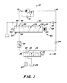
- Fig. 1 ein Beispiel für ein Hydrauliksystem, nach der Erfindung in schematischer Darstellung;
- Fig. 2 ein teilweise dargestelltes druckgesteuertes Ventil für das System nach Fig. 1;
- Fig. 3 ein weiteres Beispiel für das Hydrauliksystem, wobei das druckgesteuerte Ventil in einer Einfachversion ausgebildet ist.
- Figure 1 shows an example of a hydraulic system according to the invention in a schematic representation.
- Fig. 2 is a partially shown pressure controlled valve for the system of Fig. 1;
- Fig. 3 shows another example of the hydraulic system, wherein the pressure-controlled valve is designed in a simple version.
In der Zeichnung ist ein herkömmlicher Hydraulikmotor, wie ein in einer Richtung antreibbarer Zahnradmotor oder dergleichen, mit 10 bezeichnet. Er weist im einzelnen eine Zuführleitung 12, eine Rückführleitung 14 und eine Ablaufleitung 16 für Schmieröl des Motors auf, die an die Rückführleitung 14 angeschlossen ist. Hierzu ist die Zuführleitung und die Rückführleitung mit einer den Motor über brückenden Bypassleitung versehen, in der ein Rückschlagventil 18 vorgesehen ist, und zwar vor dem Einmündung der Abflußleitung 16 in die Bypassleitung derart, daß kein Drucköl über die Bypassleitung von der Zuführleitung in die Rückführleitung fließen kann.In the drawing, a conventional hydraulic motor, such as a gear motor or the like which can be driven in one direction, is designated by 10. In detail, it has a
Ein Steuerventil 20 steuert die Verbindung zwischen einer als Pumpe ausgebildeten Druckquelle 22, einer als Sammelbehälter ausgebildeten Rücklaufdruckquelle 24, der Zuführleitung 12 und der Rückführleitung 14. Das Steuerventil 20 kann drei Positionen einnehmen, und zwar eine Neutralstellung, in der der Zufluß zu der Zuführleitung und der Rückfluß aus der Rückführleitung unterbrochen sind, sowie eine zweite Stellung, in der der Zufluß zu dem hydraulischen Motor und der Rückfluß aus der Rückführleitung zu der Rücklaufdruckquelle gestattet sind, und eine Schwimmstellung 30. Hierzu weist das Steuerventil 20 einen Zuführanschluß 23 und einen Rücklaufanschluß 25 auf, wobei die Neutralstellung mit 26 und die Zuführstellung mit 28 bezeichnet sind. Des weiteren ist noch in der Verbindung zwischen dem Steuerventil 20 und der Zuführleitung 12 ein Regulierventil 32 vorgesehen, wobei die Rückführleitung 14 noch ein Rückschlagventil 34 aufweist, das so angeordnet ist, daß es einen Flüssigkeitsfluß von dem Rücklaufanschluß 25 in die Rückführleitung 14 unterbindet.A
In die Verbindung zwischen Regulierventil 32 und der Zuführleitung 12 ist ein druckgesteuertes Ventil 40 geschaltet, das einen Einlaß 42 aufweist, der mit dem Zuführanschluß 23, des Steuerventils 20 in Verbindung steht. Des weiteren weist das druckgesteuerte Ventil 40 noch einen ersten, zweiten und dritten Auslaß 44, 46 und 48 auf, wobei der erste Auslaß 44 mit der Rücklaufdruckquelle 24 bzw. dem Sammelbehälter in Verbindung steht, der zweite Auslaß 46 mit der Zuführleitung 12 verbunden ist und der dritte Auslaß 48 über einen Rücklauf 50 und ein Rückschlagventil 52 an die Rückführleitung 14 angeschlossen ist. Dabei ist das Rückschlagentil 52 derart angeordnet, daß es lediglich einen Zufluß aus der Rückführleitung 14 gestattet.In the connection between the regulating
Das druckgesteuerte Ventil 40 ist mit einem Ventilschieber 51 ausgerüstet, der in drei verschiedene Positionen 53, 54 und 56 verstellbar ist, wobei in der ersten Position 53 der Einlaß 42 mit dem Auslaß 46 in Verbindung steht und die Auslässe 44 und 48 blockiert sind. In der zweiten Position 54 nimmt der Ventilschieber 51 eine Stellung ein, in der der Einlaß 42 mit dem Auslaß 48 in Verbindung steht und in der die Auslässe 44 und 46 blockiert sind. In der dritten Position 56 ist der Einlaß 42 mit dem Auslaß 48 verbunden und die Auslässe 44 und 46 stehen miteinander in Verbindung. Eine Feder 58 ist vorgesehen, damit der Ventilschieber 51 in seine erste Position 53 geschoben werden kann. Die Verstellung des Ventilschiebers 51 in seine zweite und dritte Position erfolgt über einen Pilotraum 60, der über eine Pilotleitung 62 beaufschlagbar ist, die wiederum an den Rücklauf 50 angeschlossen ist.The pressure-controlled
Befindet sich das Steuerventil 20 in der Zuführstellung 28, dann wird sich normalerweise das druckgesteuerte Ventil 40 in seiner ersten Position 53, die in Fig. 1 dargestellt ist, befinden. Wenn nun aber die Rückführleitung 14 nach und nach blockiert wird, dann wird der Druck in der Rückführleitung 14 ansteigen und sich in den Pilotraum 60 fortpflanzen, wodurch der Ventilschieber 51 entgegen der Wirkung der Feder 58 in seine zweite Stellung 54 verschoben wird, in der die Zuführleitung 12 von dem Ventil 40 getrennt wird. Dadurch ist der Druck der Pumpe von dem hydraulischen Motor ebenfalls getrennt. In der Stellung 54 ist die Pumpe bzw. die Druckquelle 22 an den Pilotraum 60 über den Auslaß 48, den Kanal 50 und die Pilotleitung 62 angeschlossen, so daß sich im Pilotraum ein weiterer Druck aufbaut und den Steuerschieber 51 in seine dritte Position 56 verstellt, in der die Zuführleitung 12 mit dem Sammelbehälter bzw. der Rücklaufdruckquelle 24 über die Auslässe 46 und 44 verbunden ist und in der der Einlaß 42 nach wie vor mit dem Auslaß 48 in Verbindung steht. Dies führt zu einem weiteren Druckaufbau in dem Pilotraum 60, wodurch der Ventilschieber 51 in dieser Stellung gehalten wird.If the
Das System bleibt solange gesperrt bzw. in diesem Zustand (in der die Zuführleitung von der Druckquelle 22 abgekuppelt ist), bis die Bedienungsperson das Steuerventil 20 in die Schwimmstellung 30 verstellt, woraufhin der Pilotraum 60 mit der Rücklaufdruckquelle über die Pilotleitung 62, den Rücklauf 50, den Auslaß 48 und den Einlaß 42 verbunden ist. Hierdurch kann die Feder 58 den Ventilschieber 51 zurück in seine erste Position 53 verschieben, so daß der hydraulische Motor wiederum angetrieben werden kann, sobald das Steuerventil zurück in seine Zuführstellung 28 verstellt wird.The system remains locked or in this state (in which the supply line is uncoupled from the pressure source 22) until the operator moves the
In Fig. 2 ist der wesentliche Aufbau des druckbeaufschlagten Ventils dargestellt, und es ist aus Fig. 2 zu ersehen, daß das Ventil 40 ein Gehäuse 70 mit einer Ventilbohrung 72 aufweist, in die der Einlaß 42 und die Auslässe 44, 46 und 48 münden. In die Bohrung ist eine Hülse 74 eingesetzt, bzw. eingeschraubt, die radiale Kanäle 76, 78 und 80 aufweist, die durch Stege 82 und 84 getrennt sind, wobei jeder entsprechende Nuten mit O-Ring Dichtungen aufweist. Die Hülse 74 ist ferner mit einer inneren Ringnut 85 ausgebildet, und der Ventilschieber 51 kann in der Hülse 74 verschoben werden und weist Stege 86 und 88 auf, über die die Verbindung zwischen den Kanälen 76, 78 und 80 gesteuert wird. Der Ventilschieber 51 ist ferner noch mit einem Schaft 90 versehen, in dessen Ende ein Schlitz 92 eingearbeitet ist. Der Auslaß 44 ist durch einen axialen Kanal in der einen Endwand der Hülse 74 gebildet. Wenn nun die Rückführleitung 14 beginnt sich zu verstopfen, wird sich über den Kanal 80 in der Hülse 74, und zwar an ihrem rechtsseitigen Ende, ein Druck aufbauen, wodurch der Ventilschieber 51 nach links verschoben wird, und zwar über seine zweite Stellung, in der zunächst die Auslässe 44 und 48 gesperrt sind und der Einlaß 42 mit dem Auslaß 48 in Verbindung steht, bis daß der Ventilschieber 51 in seine dritte Stellung 56 gelangt, in der der Schaft 90 gegen die Stirnseite der Hülse 74 anliegt, in der der Auslaß 46 mit dem Sammelbehälter über den Kanal 76, die Ringnut 85, den Schlitz 92 und den Auslaß 44 in Verbindung steht, wobei der Einlaß 42 über den Kanal 78 den Pilotraum 60 druckbeaufschlagt.2 shows the essential structure of the pressurized valve, and it can be seen from FIG. 2 that the
Fig. 3 zeigt das Hydrauliksystem in einer etwas einfacheren Ausführung, wobei ein einfacheres, druckbeaufschlagbares Ventil 100 Verwendung findet, das einen Einlaß 42 und Auslässe 44 und 46, die denen des Ventiles 40 entsprechen, aufweist. Jedoch weicht das Ventil 100 insoweit von der Ausführung nach Fig. 1 ab, als es keinen dritten Auslaß 48 und somit auch keinen Kanal 50 aufweist. Der in Fig. 3 mit 102 bezeichnete Ventilschieber des Ventiles 100 kann eine erste Stellung aufweisen, in der der Einlaß 42 mit der Zuführleitung 12 über den Auslaß 46 verbunden ist, und in der der Auslaß 44 gesperrt ist. Der Ventilschieber 102 ist in eine zweite Stellung verschiebbar, in der der Einlaß 42 und die Auslässe 44 und 46 blockiert sind, wobei grundsätzlich auf eine derartige Stellung auch verzichtet werden kann. Schließlich ist der Ventilschieber 102 noch in eine dritte Stellung verstellbar, in der der Einlaß 42 blockiert ist und in der die Auslässe 44 und 46 miteinander verbunden sind, so daß die Zuführleitung 12 an den Sammelbehälter angeschlossen ist. Bei sich verstopfender Rücklaufleitung 14 wird sich in dem Pilotraum 60 ein Druck aufbauen, der den Ventilschieber 102 in seine dritte Stellung verstellt. Sobald aber der Druck sich in der Rückführleitung wieder abbaut, wird der Ventilschieber wieder in seine erste Stellung infolge der Kraft der Feder 58 zurückkehren. Funktionsmäßig unterscheidet sich das Ventil 100 also von dem Ventil 40 insoweit, daß der Ventilschieber 102 nicht mehr in seiner dritten Stellung gesperrt werden kann.Fig. 3 shows the hydraulic system in a somewhat simpler embodiment, using a simpler, pressurizable valve 100 having an
Claims (9)
Applications Claiming Priority (2)
| Application Number | Priority Date | Filing Date | Title |
|---|---|---|---|
| US799057 | 1985-11-18 | ||
| US06/799,057 US4713936A (en) | 1985-11-18 | 1985-11-18 | Motor seal protector valve |
Publications (2)
| Publication Number | Publication Date |
|---|---|
| EP0224156A2 true EP0224156A2 (en) | 1987-06-03 |
| EP0224156A3 EP0224156A3 (en) | 1989-04-26 |
Family
ID=25174944
Family Applications (1)
| Application Number | Title | Priority Date | Filing Date |
|---|---|---|---|
| EP86115882A Withdrawn EP0224156A3 (en) | 1985-11-18 | 1986-11-15 | Hydraulic system with a hydraulic motor and a pressure-operated valve |
Country Status (11)
| Country | Link |
|---|---|
| US (1) | US4713936A (en) |
| EP (1) | EP0224156A3 (en) |
| JP (1) | JPS62118104A (en) |
| KR (1) | KR870005190A (en) |
| CN (1) | CN86107785A (en) |
| AR (1) | AR247606A1 (en) |
| AU (1) | AU6417286A (en) |
| BR (1) | BR8605637A (en) |
| CA (1) | CA1265977A (en) |
| DK (1) | DK549386A (en) |
| ZA (1) | ZA868702B (en) |
Cited By (1)
| Publication number | Priority date | Publication date | Assignee | Title |
|---|---|---|---|---|
| WO2007051254A1 (en) * | 2005-11-04 | 2007-05-10 | Mark Andrew Fogarty | Pressure release valve, system and method of use |
Families Citing this family (4)
| Publication number | Priority date | Publication date | Assignee | Title |
|---|---|---|---|---|
| DE3812300C1 (en) * | 1988-04-13 | 1989-03-02 | Hydromatik Gmbh, 7915 Elchingen, De | |
| US5197284A (en) * | 1989-07-21 | 1993-03-30 | Cartner Jack O | Hydraulic motor deceleration system |
| DE4231189A1 (en) * | 1992-09-17 | 1994-03-24 | Rexroth Mannesmann Gmbh | Safety circuit for a servo-hydraulic control system |
| US7896188B2 (en) * | 2007-03-16 | 2011-03-01 | National Steel And Shipbuilding Company | Universal support arrangement for semi-membrane tank walls |
Citations (5)
| Publication number | Priority date | Publication date | Assignee | Title |
|---|---|---|---|---|
| GB345203A (en) * | 1929-07-17 | 1931-03-04 | Cuttat Sa Des Ets | Regulator for hydraulic cylinders |
| FR2280815A1 (en) * | 1974-08-02 | 1976-02-27 | Kloeckner Humboldt Deutz Ag | Agricultural vehicle hydraulic control system - has sprung changeover slide blocked by neutral position of power jack slide |
| US4218957A (en) * | 1977-10-03 | 1980-08-26 | Borg-Warner Corporation | Flow control valve |
| US4520625A (en) * | 1982-03-04 | 1985-06-04 | Kabushiki Kaisha Komatsu Seisakusho | Hydraulic brake valve system |
| US4520626A (en) * | 1981-01-10 | 1985-06-04 | Hitachi Construction Machinery Co., Ltd. | Hydraulic drive system for single rod cylinder |
Family Cites Families (13)
| Publication number | Priority date | Publication date | Assignee | Title |
|---|---|---|---|---|
| US3125324A (en) * | 1964-03-17 | Vivier | ||
| GB345337A (en) * | 1929-10-08 | 1931-03-19 | Cuttat Sa Des Ets | Regulator for a hydraulic cylinder |
| US3411416A (en) * | 1965-01-29 | 1968-11-19 | Eton Yale & Towne Inc | Adjustable, metered, directional flow control arrangement |
| US3470792A (en) * | 1967-08-02 | 1969-10-07 | Cessna Aircraft Co | Maximum pressure control apparatus for hydraulic actuators |
| CH525413A (en) * | 1970-06-26 | 1972-07-15 | Von Roll Ag | Hydrostatic reversing gear |
| SE344053B (en) * | 1970-07-01 | 1972-03-27 | Bygg Och Transportekonomie Ab | |
| US3771422A (en) * | 1971-10-13 | 1973-11-13 | Houdaille Industries Inc | Automatic pressure relief and snubbing in hydraulic actuators |
| US3942413A (en) * | 1974-08-01 | 1976-03-09 | Borg-Warner Corporation | Load limiting system |
| US3915068A (en) * | 1974-08-30 | 1975-10-28 | Deere & Co | Hydrostatic transmission |
| GB1483396A (en) * | 1975-02-14 | 1977-08-17 | Coal Ind | Methods of and apparatus for controlling hydraulic equipment |
| US4040439A (en) * | 1976-03-29 | 1977-08-09 | Eaton Corporation | Cushion valve arrangement |
| US4114516A (en) * | 1976-10-15 | 1978-09-19 | Caterpillar Tractor Co. | Anti-cavitation and pressure modulating relief valve for controlling hydraulic cylinders |
| JPS5472376A (en) * | 1977-11-22 | 1979-06-09 | Daikin Ind Ltd | Hydraulic circuit |
-
1985
- 1985-11-18 US US06/799,057 patent/US4713936A/en not_active Expired - Fee Related
-
1986
- 1986-10-02 CA CA000519666A patent/CA1265977A/en not_active Expired - Fee Related
- 1986-10-16 AU AU64172/86A patent/AU6417286A/en not_active Abandoned
- 1986-10-31 AR AR86305761A patent/AR247606A1/en active
- 1986-11-13 JP JP61270844A patent/JPS62118104A/en active Pending
- 1986-11-14 BR BR8605637A patent/BR8605637A/en unknown
- 1986-11-14 CN CN198686107785A patent/CN86107785A/en active Pending
- 1986-11-15 EP EP86115882A patent/EP0224156A3/en not_active Withdrawn
- 1986-11-17 DK DK549386A patent/DK549386A/en not_active Application Discontinuation
- 1986-11-17 KR KR860009682A patent/KR870005190A/en not_active Application Discontinuation
- 1986-11-17 ZA ZA868702A patent/ZA868702B/en unknown
Patent Citations (5)
| Publication number | Priority date | Publication date | Assignee | Title |
|---|---|---|---|---|
| GB345203A (en) * | 1929-07-17 | 1931-03-04 | Cuttat Sa Des Ets | Regulator for hydraulic cylinders |
| FR2280815A1 (en) * | 1974-08-02 | 1976-02-27 | Kloeckner Humboldt Deutz Ag | Agricultural vehicle hydraulic control system - has sprung changeover slide blocked by neutral position of power jack slide |
| US4218957A (en) * | 1977-10-03 | 1980-08-26 | Borg-Warner Corporation | Flow control valve |
| US4520626A (en) * | 1981-01-10 | 1985-06-04 | Hitachi Construction Machinery Co., Ltd. | Hydraulic drive system for single rod cylinder |
| US4520625A (en) * | 1982-03-04 | 1985-06-04 | Kabushiki Kaisha Komatsu Seisakusho | Hydraulic brake valve system |
Cited By (2)
| Publication number | Priority date | Publication date | Assignee | Title |
|---|---|---|---|---|
| WO2007051254A1 (en) * | 2005-11-04 | 2007-05-10 | Mark Andrew Fogarty | Pressure release valve, system and method of use |
| AU2006308808B2 (en) * | 2005-11-04 | 2013-09-19 | Mark Andrew Fogarty | Pressure release valve, system and method of use |
Also Published As
| Publication number | Publication date |
|---|---|
| AU6417286A (en) | 1987-05-21 |
| US4713936A (en) | 1987-12-22 |
| BR8605637A (en) | 1987-08-18 |
| DK549386D0 (en) | 1986-11-17 |
| DK549386A (en) | 1987-05-19 |
| CA1265977A (en) | 1990-02-20 |
| KR870005190A (en) | 1987-06-05 |
| AR247606A1 (en) | 1995-01-31 |
| JPS62118104A (en) | 1987-05-29 |
| EP0224156A3 (en) | 1989-04-26 |
| CN86107785A (en) | 1987-05-27 |
| ZA868702B (en) | 1988-07-27 |
Similar Documents
| Publication | Publication Date | Title |
|---|---|---|
| DE2938743C2 (en) | ||
| DE3118576A1 (en) | CONTROL DEVICE FOR A PUMP | |
| DE2848208B1 (en) | Pilot operated pressure relief valve with feed function | |
| DE2858210C2 (en) | Device to compensate for viscosity reductions in the adjusting device of a hydraulic pump | |
| EP0103250B1 (en) | Fluid control control valve | |
| EP0935713B1 (en) | Valve system and manufacture of same | |
| DE3313390A1 (en) | OIL PUMP ARRANGEMENT | |
| DE2916575C2 (en) | Current regulator | |
| DE2001680A1 (en) | Hydraulic control valve | |
| DE10247507A1 (en) | Hydraulic control device for heavy construction equipment has first seat valve displaced by difference between load pressure of load line and discharge pressure of hydraulic pump in hydraulic line between pump line and feeder lines | |
| DE3433333A1 (en) | HYDRAULIC CONTROL CIRCUIT FOR AN AUTOMATIC MOTOR VEHICLE TRANSMISSION | |
| DE2553748A1 (en) | HYDRAULIC CONTROL DEVICE, IN PARTICULAR FOR VEHICLE STEERING | |
| DE2713653A1 (en) | PRESSURE REGULATOR FOR HYDRAULICALLY ACTUATED COUPLINGS | |
| DE2910623C2 (en) | Control device for a hydraulic system | |
| EP0224156A2 (en) | Hydraulic system with a hydraulic motor and a pressure-operated valve | |
| DE2523937A1 (en) | HYDRAULIC CONTROL DEVICE | |
| DE3532591C2 (en) | ||
| DE3630792C2 (en) | Pressure generating device | |
| EP0955474A2 (en) | Pressurised oil system with oil filter, and gearbox fitted with such | |
| DE3810943C2 (en) | ||
| DE3801072C1 (en) | ||
| DE3407827C2 (en) | Diaphragm seal | |
| WO1995033136A1 (en) | Hoisting-gear control system with control valve | |
| DE2319135B2 (en) | Switching valve of a pressure medium supply device for a hydrostatic power steering for vehicles | |
| DE2655966B2 (en) | Hydraulic delivery rate adjustment system for the adjustment pump of a hydrostatic transmission |
Legal Events
| Date | Code | Title | Description |
|---|---|---|---|
| PUAI | Public reference made under article 153(3) epc to a published international application that has entered the european phase |
Free format text: ORIGINAL CODE: 0009012 |
|
| AK | Designated contracting states |
Kind code of ref document: A2 Designated state(s): AT BE CH DE ES FR GB IT LI NL SE |
|
| 17P | Request for examination filed |
Effective date: 19871124 |
|
| PUAL | Search report despatched |
Free format text: ORIGINAL CODE: 0009013 |
|
| AK | Designated contracting states |
Kind code of ref document: A3 Designated state(s): AT BE CH DE ES FR GB IT LI NL SE |
|
| RHK1 | Main classification (correction) |
Ipc: F15B 13/02 |
|
| STAA | Information on the status of an ep patent application or granted ep patent |
Free format text: STATUS: THE APPLICATION HAS BEEN WITHDRAWN |
|
| 18W | Application withdrawn |
Withdrawal date: 19890506 |
|
| R18W | Application withdrawn (corrected) |
Effective date: 19890506 |
|
| RIN1 | Information on inventor provided before grant (corrected) |
Inventor name: BURK, RONNIE FRANKLIN Inventor name: DELFS, LARRY MARVIN Inventor name: BARBER, DENNIS RAY |