EP0223398B1 - Vehicle antenna system - Google Patents
Vehicle antenna system Download PDFInfo
- Publication number
- EP0223398B1 EP0223398B1 EP86307847A EP86307847A EP0223398B1 EP 0223398 B1 EP0223398 B1 EP 0223398B1 EP 86307847 A EP86307847 A EP 86307847A EP 86307847 A EP86307847 A EP 86307847A EP 0223398 B1 EP0223398 B1 EP 0223398B1
- Authority
- EP
- European Patent Office
- Prior art keywords
- vehicle
- trim strip
- antenna
- vehicle body
- free
- Prior art date
- Legal status (The legal status is an assumption and is not a legal conclusion. Google has not performed a legal analysis and makes no representation as to the accuracy of the status listed.)
- Expired - Lifetime
Links
- 239000002184 metal Substances 0.000 claims description 7
- 239000004033 plastic Substances 0.000 claims description 7
- 229920003023 plastic Polymers 0.000 claims description 7
- 230000001681 protective effect Effects 0.000 claims description 2
- 239000000463 material Substances 0.000 claims 1
- 238000000465 moulding Methods 0.000 description 33
- 230000035945 sensitivity Effects 0.000 description 11
- 239000000523 sample Substances 0.000 description 10
- 239000005357 flat glass Substances 0.000 description 6
- 230000004907 flux Effects 0.000 description 6
- 239000004020 conductor Substances 0.000 description 5
- 125000006850 spacer group Chemical group 0.000 description 5
- 238000005259 measurement Methods 0.000 description 4
- 239000000758 substrate Substances 0.000 description 4
- 238000004804 winding Methods 0.000 description 4
- 239000003990 capacitor Substances 0.000 description 3
- 238000005094 computer simulation Methods 0.000 description 3
- 238000004519 manufacturing process Methods 0.000 description 3
- 238000000034 method Methods 0.000 description 3
- 238000010276 construction Methods 0.000 description 2
- 230000007423 decrease Effects 0.000 description 2
- 238000001514 detection method Methods 0.000 description 2
- 238000002474 experimental method Methods 0.000 description 2
- 239000011810 insulating material Substances 0.000 description 2
- 239000000615 nonconductor Substances 0.000 description 2
- 238000012545 processing Methods 0.000 description 2
- 238000004891 communication Methods 0.000 description 1
- 230000008878 coupling Effects 0.000 description 1
- 238000010168 coupling process Methods 0.000 description 1
- 238000005859 coupling reaction Methods 0.000 description 1
- 230000001419 dependent effect Effects 0.000 description 1
- 238000013461 design Methods 0.000 description 1
- 230000002349 favourable effect Effects 0.000 description 1
- 238000010422 painting Methods 0.000 description 1
Images


Classifications
-
- H—ELECTRICITY
- H01—ELECTRIC ELEMENTS
- H01Q—ANTENNAS, i.e. RADIO AERIALS
- H01Q1/00—Details of, or arrangements associated with, antennas
- H01Q1/27—Adaptation for use in or on movable bodies
- H01Q1/32—Adaptation for use in or on road or rail vehicles
- H01Q1/325—Adaptation for use in or on road or rail vehicles characterised by the location of the antenna on the vehicle
- H01Q1/3291—Adaptation for use in or on road or rail vehicles characterised by the location of the antenna on the vehicle mounted in or on other locations inside the vehicle or vehicle body
Definitions
- the pole antenna is also disadvantageous in that it may accidentally or intentionally be subject to damage and in that the pole antenna may produce unpleasant noises when the vehicle is running at high speeds. Therefore, it is strongly desired to eliminate the pole antenna from the vehicle body.
- the antenna wire may be disposed spaced apart from the marginal portion of the vehicle body within 3.6 centimeters for a carrier frequency equal to 100 MHz. As the level of the carrier frequency f increases, the antenna wire must correspondingly be approached to the marginal edge of the vehicle body.
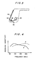
- Figure 4 shows the receiving sensitivity of the antenna wire in the first embodiment wherein a curve "a” indicates the sensitivity of the antenna wire 42 having its length equal to 1800 mm and a curve "b" represents the sensitivity of the antenna wire having its length equal to 900 mm.
- the reception may be improved by adjusting the length of the antenna wire 42 dependent on a frequency band to be received.
- the level of the induced currents can be increased to improve the receiving sensitivity by electrically separating the vehicle frame from the metallic trim strip.
Landscapes
- Engineering & Computer Science (AREA)
- Remote Sensing (AREA)
- Details Of Aerials (AREA)
Description
- The present invention relates to vehicle antenna systems for detecting broadcast radio frequency signals.
- A pole type antenna is known as one of the conventional vehicle antenna systems. The pole antenna projects outwardly from the vehicle body and exhibits a favorable reception performance in its own way. However, the pole antenna was always an obstruction from the viewpoint of vehicle body design.
- The pole antenna is also disadvantageous in that it may accidentally or intentionally be subject to damage and in that the pole antenna may produce unpleasant noises when the vehicle is running at high speeds. Therefore, it is strongly desired to eliminate the pole antenna from the vehicle body.
- Recently, the number of frequency bands for broadcast or communication wave signals to be received by automobiles has increased. If a plurality of pole antennas are located on a vehicle body matching the increased number of frequency bands, they would greatly damage the aesthetic concept of the vehicle appearance. Furthermore, there will be created electrical interference between the pole antennas to degrade their reception performance.
- Some attempts have been made to eliminate or conceal pole antennas. One of such attempts is that an antenna wire is applied to a rear window glass on a vehicle body.
- Another proposal has been made to detect surface currents induced on the vehicle body by broadcast wave signals. Although it appears that such a proposal apparently provides the most positive and efficient method of utilizing the surface currents flowing on the vehicle body, many actual experiments showed that the method failed, contrary to the above expectation.
- One of the main reasons why the surface currents on the vehicle body could not be utilized is that the level of the surface currents is not as large as expected. The prior art mainly intended to detect surface currents flowing on the roof panel of the vehicle body. However, the surface currents on the roof panel do not reach a level sufficient to be utilized in a vehicle antenna system.
- The second reason is that the surface currents include a high percentage of noise. The noise is created mainly by the engine ignition system and the battery charging regulator system and therefore cannot be eliminated while the engine is running.
- There have been made some proposals to overcome such problems. For example, Japanese Patent Publication Sho 53-22 418 discloses a vehicle antenna system for utilizing surface currents induced on the vehicle body by broadcast wave signals, in which an electrical insulator is formed on the vehicle body at a location where the surface currents flow concentratedly. The currents are detected directly by a sensor between the opposite ends of the electrical insulator. Such an arrangement can detect practicable signals which are superior in S/N ratio. However, the vehicle body must partially be cut away to form a space for housing the antenna construction. This is not acceptable in mass-production.
- Japanese Utility Model Publication Sho 53-34 826 discloses an antenna system comprising a pick-up coil for detecting currents on the pillar of the vehicle body. Such a proposal is certainly advantageous in that the antenna can completely be housed within the vehicle body. However, it is not practical since the pick-up coil has to be disposed near the pillar in the direction perpendicular to the length of the pillar. Furthermore, such an arrangement cannot provide practicable antenna outputs and appears to be merely an idea.
- As described above, the prior art was not successful in providing an antenna system which detects currents induced on the vehicle body by broadcast wave signals. Rather, many experiments suggested that the antenna system utilizing currents on the vehicle body could not be accomplished.
- The prior art antenna systems were mainly intended to receive AM band waves meeting the needs of the times. Therefore, the prior art antenna systems for detecting the surface currents on the vehicle body would not obtain good characteristics of reception because the wavelength of the broadcast wave signals to be received is too long for the antenna systems. Accordingly the present invention is aimed at handling broadcast wave signals at a frequency above 50 MHz, i.e. in the FM band. Thus, the reception of broadcast wave signals from surface currents on the vehicle body, which was considered to be practically impossible, can very efficiently be made in accordance with the present invention.
- An object of the present invention is to provide an improved vehicle antenna system whereby surface currents induced on the vehicle body by broadcast radio frequency signals at a frequency above 50 MHz can efficiently be detected.
- DE-A 1 949 828 describes a vehicle antenna system comprising an antenna mounted adjacent a metal vehicle body portion to detect radio frequency surface currents induced in said body portion by broadcast radio frequency signals.
- The present invention is characterized in that:
- in order to be suitable for detecting such radio frequency surface currents at a frequency above 50 MHz, which surface currents have a concentrated flow along a marginal edge portion of said body portion;
- said body portion is a metallic protective trim strip forming a portion of the visible exterior of the vehicle;
- said trim strip having its longer edges free and being fastened to the vehicle body structure by fastener means on its inner surface; and
- said antenna comprises an elongate conductive pick-up element which extends adjacent to one of the marginal edge portions of said trim strip lengthwise of one of said free longer edges thereof, and which is electrically insulated with respect to said trim strip.
- The trim strip is preferably electrically insulated from the metal frame of the vehicle to increase the density of high frequency surface currents induced on the surface of the trim strip.
- The length of the trim strip may be equal to about one half wavelength for the lower VHF band (
channels 1 to 3 in Japan), to about one wavelength for the higher VHF band (channels 4 to 11 in Japan), and to about two to four wavelengths for UHF bands. - Embodiments of the present invention will now be described, by way of example, with reference to the accompanying drawings, in which:
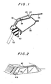
- Figure 1 illustrates a first embodiment of a vehicle antenna system constructed according to the present invention.
- Figure 2 is a perspective view of the antenna wire arranded along the trim strip.
- Figure 3 illustrates the connection of the antenna wire with a coaxial cable.
- Figure 4 is a graph showing the characteristics of receiving sensitivity in the first embodiment.
- Figure 5 illustrates a second embodiment of a ve- hicte antenna system constructed according to the present invention.
- Figure 6 illustrates the mounting of the antenna system shown in Figure 5.
- Figure 7 illustrates a third embodiment of a vehicle antenna system constructed according to the present invention.
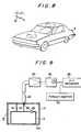
- Figure 8 illustrates surface currents I induced on a vehicle body B by external waves W.
- Figure 9 illustrates a probe and its processing circuit used to determine the distribution of surface currents on the vehicle body.
- Figure 10 illustrates the electromagnetic coupling between the surface currents I and a pick-up loop antenna.
- Figure 11 illustrates the directional pattern of the loop antenna shown in Figure 10.
- Figure 12 illustrates the distribution of surface current intensity on the vehicle body.
- Figure 13 illustrates the orientation of surface currents on the vehicle body.
- Referring first to Figures 8 through 10, there will be described a process of measuring the distribution of high frequency currents on the vehicle body and determining a location at which an antenna system according to the present invention can most efficiently receive broadcast wave signals, prior to the detailed description of preferred embodiments of the present invention.
- Figure 8 shows that as external waves W such as broadcast waves and other waves pass through a vehicle body B of conductive metal, surface currents I of various different levels are induced on the vehicle body B at various different locations, depending on the intensity of the external waves. The present invention intends only to receive external waves having frequencies which belong to relatively high frequency bands equal to or higher than 50 MHz, such as FM band waves, TV band waves.
- The distribution of surface currents is determined by computer simulation and actual measurements of current level at various locations or the vehicle. A probe is used which is constructed in accordance with the same principle as that of a high frequency pick-up mounted on the vehicle body at a desired location, as will be described. The probe is moved along the surface of the vehicle body over the entire area thereof while varying its orientation at the respective locations on the vehicle body.
- Figure 9 shows the schematic construction of such a probe P which comprises a
casing 10 of conductive material for avoiding the ingress of external waves and aloop coil 12 housed within thecasing 10. Thecasing 10 is provided with an opening 10a through which a portion of theloop coil 12 is externally exposed. The exposed portion of theloop coil 12 is disposed in close proximity to the surface of the vehicle bondy B such that a magnetic flux created by the surface currents on the vehicle body can be detected by theloop coil 12. Theloop coil 12 is electrically connected to the casing through a short-circuiting line 14. Theoutput end 16 of theloop coil 12 is electrically connected to acore conductor 20 in acoaxial cable 18. Theloop coil 12 includes acapacitor 22 for causing the frequency of theloop coil 12 to resonate with a desired frequency to be measured to improve the pick-up efficiency. - As seen from Figure 9, the output of the probe P is amplified by a high
frequency voltage amplifier 24 the output voltage of which can be measured at a highfrequency voltage meter 26. The output voltage of theamplifier 24 also is recorded by anX-Y recorder 28 as one of the current levels at the respective locations of the vehicle body. TheX-Y recorder 28 also receives a signal indicative of the respective one of various locations on the vehicle body. In such a manner, the level of the high frequency surface currents at that location can be determined. As the probe P is moved along the surface of the vehicle body B while it is angularly rotated at the respective locations of measurements, therefore, the distribution and orientation of the surface currents on the vehicle body can accurately be determined. - Figure 10 shows a declination 0 between the high frequency surface currents I and the
loop coil 12 of said probe. As shown, a magnetic flux 0 created by the currents I causes a detection voltage V to generate in theloop coil 12 when the magnetic flux 0 intersects theloop coil 12. As seen from Figure 11, the detection voltage V becomes maximum when the declination 0 is equal to zero, that ist, when the surface currents I are parallel to theloop coil 12 of the probe. Thus, the orientation of the surface currents I can be determined when the maximum voltage is obtained by rotating the probe P at each of the locations on the vehicle body. - Figures 12 and 13 show the magnitude and orientation of the high frequency surface currents at the respective vehicle locations for a frequency equal to 80 MHz, such magnitude and orientation of the surface currents being obtained from both the computer simulation and the actual measurements by said probe P. As seen from Figure 12, the magnitude of the surface currents is larger at locations extending along the marginal edges of flat sections on the vehicle body and becomes very small at the central portion of each of the flat vehicle sections.
- As seen from Figure 13, the surface currents flow concentratedly on the vehicle body in the direction parallel to each of the marginal portions of the vehicle body and extending along each of the connections between each adjacent flat sections.
- Studying the distribution of surface currents induced on the aforementioned metallic vehicle portion along the longitudinal line A on the vehicle body, it has been found that the level of the surface currents decreases as a distance apart from the end or marginal portion of the vehicle body increases. Since the range of current level in which actually acceptable sensitivities can be obtained is equal to or less than 6 decibels, it is understood that very sensitivity can be obtained if the distance from any edge of the vehicle body is within 4.5 centimeters.
- The antenna wire is electrically insulated from the outer surface of the vehicle body B such as a so-called side molding, roof retainer, front window molding or the like, and is also arranged extending along the edge of that outer surface. In order to obtain very good sensitivity in practice, the distance apart from the edge is preferably set within a range depending on the carrier frequency of the broadcast waves.
- For example, if the antenna wire is spaced apart from the marginal edge of the vehicle body within 4.5 centimeters for the carrier frequency equal to 80 MHz, a sufficiently practicable antenna system can be provided.
- From the computer simulation and the actual measurements, it has been found that such practicable distance varies depending on the carrier frequency to be used and that the practicable distance decreases as the level of the carrier frequency increases.
- From the fact that the practicable distance is inversely proportional to the level of the carrier frequency, a good reception for each of the carrier frequencies can be made if the high frequency pick-up is spaced apart from the marginal portion of any flat metal part on the vehicle body within a range represented by:

- For example, the antenna wire may be disposed spaced apart from the marginal portion of the vehicle body within 3.6 centimeters for a carrier frequency equal to 100 MHz. As the level of the carrier frequency f increases, the antenna wire must correspondingly be approached to the marginal edge of the vehicle body.
- Referring now to Figure 1, there is shown a first embodiment of the present invention which is applied to a trim strip being a so-called molding on the vehicle body. A metallic side molding has its longer edges free, is disposed along the vehicle body and is electrically insulated from the other metal vehicle parts such as a
roof panel 36 and aninner header panel 38 by means of aplastics spacer fastener 34 on its inner surface. Theinner header panel 38 is connected to aside window glass 52 through aweather strip 50. Theside molding 32 includes aplastics part 40 integrally molded thereover at one edge and extending along the length of theside molding 32. Anantenna wire 42 is embedded in theplastics part 40 such that theantenna wire 42 can positively be positioned in place within a range depending on the level of a carrier frequency to be received. - The
side molding 32 may be formed to have its length equal to about one half wavelength for the lower VHF band (channels 1 to 3 in Japan), about one wavelength for the higher VHF band, and about 2-4 wavelengths for UHF bands. This provides an increased receiving sensitivity. - To this end, the
antenna wire 42 and theplastics part 40 can simultaneously be molded with theside molding 32. Theantenna wire 42 is disposed in close proximity to the marginal edge of theside molding 32 and is electrically insulated from that marginal edge. Thus, a magnetic flux induced by the high frequency surface currents flowing on said marginal edge can positively be caught by theantenna wire 42. As a result, the currents induced on the vehicle body can more sensitively be detected by the antenna system. - Figure 2 shows the outline of the
antenna wire 42 mounted on the marginal edge of theside molding 32 while Figure 3 indicates the connection of the antenna wire with acoaxial cable 44. - More particularly, the
antenna wire 42 includes a free end located at theplastics part 40 with the other end thereof electrically connected to the core of thecoaxial cable 44. Thecoaxial cable 44 also includes a sheath conductor connected to the vehicle frame by means of abracket 46. Thecoaxial cable 44 extends into the interior of the vehicle body through aservice hole 48 which is formed in the vehicle frame at the rear end of theside molding 32. Thecoaxial cable 44 is electrically connected with an onboard receiver (not shown) which has circuitry containing a preamplifier and other instruments for processing signals transmitted from the antenna wire through the coaxial cable. - Figure 4 shows the receiving sensitivity of the antenna wire in the first embodiment wherein a curve "a" indicates the sensitivity of the
antenna wire 42 having its length equal to 1800 mm and a curve "b" represents the sensitivity of the antenna wire having its length equal to 900 mm. As seen from Figure 4, the reception may be improved by adjusting the length of theantenna wire 42 dependent on a frequency band to be received. - As will be apparent from the foregoing, the first embodiment of the present invention may easily be assembled onto the vehicle since the antenna wire is integrally molded on the trim strip on molding and painting it. The first embodiment of the present invention also is inexpensive to manufacture since the antenna wire forms part of the trim strip. Any particular adjustment is not required on assembling since the frequency bands to be received can easily be selected by adjusting the length of the antenna wire.
- Referring next to Figure 5, there is shown a second embodiment of a vehicle antenna system according to the present invention which is also applied to a side molding on the vehicle body.
- In Figure 5, a
metallic side molding 232 has its longer edges free, is arranged extending along the vehicle body and is electrically insulated from aroof panel 236 and aninner header panel 238 by means of a plastics spacer/fastener 234 or its inner surface. The inner header panel 138 is connected to aside window glass 242 through aweather strip 240. Other weather strips 244 and 246 for preventing the ingress of rainwater are located between the inner periphery of theside molding 232 and theinner header panel 238. - The
inner header panel 238 includesopenings loop antenna 248 defining the antenna means. - The
loop antenna 248 is disposed in close proximity to the inner face of theside molding 232 through theopenings - More particularly, the
inner header panel 238 includes asubstrate 254 located to close theopening 250. Thesubstrate 254 is mounted on theinner header panel 238 by means offasteners 258 throughspacers 256. - The
loop antenna 248 is in the form of a single winding. As shown in Figure 6, aresonance capacitor 260 is electrically connected in series between the single windingantenna 248 and the sheath conductor of acoaxial cable 262. Theloop antenna 248 is coated with an electrical insulating material such that it can be disposed in intimate contact with theside molding 232 and also electrically insulated from theside molding 232. Thus, a magnetic flux created by the surface currents can more intensively intersect theloop antenna 248. - In such an arrangement, the
loop antenna 248 is pressed against the surface of theside molding 232 and located spaced apart from the edge of theside molding 232 within the distance represented by:
coaxial cable 262 and then processed by circuitry in the receiver. - The
side molding 232 may be formed to have its length equal to about are half wavelength for the lower VHF band (channels 1 to 3 in Japan), about one wavelength for the VHF band, and about 2-4 wavelengths for UHF bands. This provides an increased receiving sensitivity. - The metallic trim strip may be a part other than the side molding, for example, a front window glass molding or a rear window glass molding.
- As will be apparent from the foregoing, the level of the induced currents can be increased to improve the receiving sensitivity by electrically separating the vehicle frame from the metallic trim strip.
- Since the antenna system can completely be housed within the vehicle frame, no part of the antenna system will extend inwardly into the interior of the vehicle passenger room.
- Referring next to Figure 7, there is shown a third embodiment of a vehicle antenna system according to the present invention which is also applied to a side molding on the vehicle.
- In Figure 7, a
metallic side molding 332 is rigidly mounted on aninner header panel 338 by means of afastener 334 which extends outwardly from the inner wall of theside molding 332 and is fitted into an opening in theinner header panel 338. Theinner header panel 338 is arranged extending along the vehicle body and is electrically insulated from aroof panel 336. - The
inner header panel 338 is connected to aside window glass 342 through aweather strip 340. Other weather strips 344 and 346 for preventing the ingress of rainwater are located between the inner periphery of theside molding 332 and theinner header panel 338. - The
inner header panel 338 includesopenings loop antenna 348 defining the antenna means. Theloop antenna 348 is disposed in close proximity to the inner face of theside molding 332 through theopenings - More particularly, the
inner header panel 338 includes asubstrate 354 located to close theopening 350. Thesubstrate 354 is mounted on theinner header panel 338 by means offasteners 358 throughspacers 356. - In such a manner, the respective mountings of the
side 332 and antenna system on theinner header panel 338 and vehicle frame can be simplified to reduce the number of assembling steps. - The
loop antenna 348 is in the form of a single winding. As in the second embodiment, a resonance capacitor is electrically connected in series between the single windingantenna 348 and the sheath conductor of acoaxial cable 362. Theloop antenna 348 is coated with an electrical insulating material such that it can be disposed in intimate contact with theside molding 332 and also electrically insulated from theside molding 332. Thus, a magnetic flux created by the surface currents can more intensively intersect theloop antenna 348. - In such an arrangement, the
loop antenna 348 is pressed against the surface of theside molding 332 and located spaced apart from the edge of theside molding 332 within the distance represented by:
coaxial cable 362 and then processed by the circuitry in the receiver. - This antenna system has improved receiving sensitivity and ease of manufacture since no spacer and other similar means for electrically insulating between the vehicle frame and the metallic trim strip are required. Any control of the gap and electric conduction between the vehicle frame and the metallic trim strip is not required since the metallic trim strip includes fastener means extending outwardly from the inner wall of the metallic trim strip, the fastener means being adapted to mount the metallic trim strip on the vehicle frame under the electric conductive state.
Claims (8)
Applications Claiming Priority (6)
| Application Number | Priority Date | Filing Date | Title |
|---|---|---|---|
| JP24361185A JPS62102606A (en) | 1985-10-29 | 1985-10-29 | Antenna system for automobile |
| JP243611/85 | 1985-10-29 | ||
| JP244717/85 | 1985-10-30 | ||
| JP24471785A JPS62104204A (en) | 1985-10-30 | 1985-10-30 | Antenna system for automobile |
| JP245367/85 | 1985-10-31 | ||
| JP24536785A JPS62104301A (en) | 1985-10-31 | 1985-10-31 | Antenna system for automobile |
Publications (2)
| Publication Number | Publication Date |
|---|---|
| EP0223398A1 EP0223398A1 (en) | 1987-05-27 |
| EP0223398B1 true EP0223398B1 (en) | 1990-12-19 |
Family
ID=27333156
Family Applications (1)
| Application Number | Title | Priority Date | Filing Date |
|---|---|---|---|
| EP86307847A Expired - Lifetime EP0223398B1 (en) | 1985-10-29 | 1986-10-10 | Vehicle antenna system |
Country Status (3)
| Country | Link |
|---|---|
| US (1) | US4804967A (en) |
| EP (1) | EP0223398B1 (en) |
| DE (1) | DE3676279D1 (en) |
Families Citing this family (10)
| Publication number | Priority date | Publication date | Assignee | Title |
|---|---|---|---|---|
| US5587715A (en) * | 1993-03-19 | 1996-12-24 | Gps Mobile, Inc. | Method and apparatus for tracking a moving object |
| EP0830792A4 (en) * | 1995-06-06 | 2000-04-26 | Flash Comm Inc | Determining propagating and clear frequency in wireless data communications network |
| US5734963A (en) * | 1995-06-06 | 1998-03-31 | Flash Comm, Inc. | Remote initiated messaging apparatus and method in a two way wireless data communications network |
| US5589844A (en) * | 1995-06-06 | 1996-12-31 | Flash Comm, Inc. | Automatic antenna tuner for low-cost mobile radio |
| US5765112A (en) * | 1995-06-06 | 1998-06-09 | Flash Comm. Inc. | Low cost wide area network for data communication using outbound message specifying inbound message time and frequency |
| US6353415B1 (en) * | 2000-11-13 | 2002-03-05 | Delphi Technologies, Inc. | Molded in place antenna assembly and method of making same |
| BRPI0416625A (en) * | 2003-11-17 | 2007-01-16 | Sst Wireless Inc | bodywork antenna |
| DE102011012963B3 (en) | 2011-03-04 | 2012-05-10 | Audi Ag | Antenna arrangement in a motor vehicle |
| WO2013066451A1 (en) * | 2011-08-12 | 2013-05-10 | Bae Systems Information And Electronic Systems Integration Inc. | Wide band embedded armor antenna using double parasitic elements |
| US10062967B2 (en) | 2011-08-12 | 2018-08-28 | Bae Systems Information And Electronic Systems Integration Inc. | Wide band antenna having a driven bowtie dipole and parasitic bowtie dipole embedded within armor panel |
Citations (1)
| Publication number | Priority date | Publication date | Assignee | Title |
|---|---|---|---|---|
| DE1949828A1 (en) * | 1968-10-04 | 1970-04-30 | Portenseigne Ets Marcel | Method and device for receiving radio frequency signals |
Family Cites Families (54)
| Publication number | Priority date | Publication date | Assignee | Title |
|---|---|---|---|---|
| GB485062A (en) * | 1936-07-11 | 1938-05-13 | Opel Adam Ag | Antennae for receiving radio transmissions in motor vehicles |
| US2200674A (en) * | 1939-05-04 | 1940-05-14 | Jr Eugene F Mcdonald | Radio apparatus |
| US2404093A (en) * | 1941-06-28 | 1946-07-16 | Rca Corp | Antenna |
| US2481978A (en) * | 1947-01-22 | 1949-09-13 | Joseph B Clough | Automobile radio coupler and method of communication |
| US2520986A (en) * | 1947-10-22 | 1950-09-05 | Motorola Inc | Vehicular antenna system |
| US2575471A (en) * | 1950-04-13 | 1951-11-20 | Philco Corp | Vehicular antenna system |
| DE889618C (en) * | 1951-09-27 | 1953-09-10 | Lorenz C Ag | Vehicle antenna system |
| US2740113A (en) * | 1952-01-03 | 1956-03-27 | Bendix Aviat Corp | Magnetic antenna systems |
| US2774811A (en) * | 1954-03-02 | 1956-12-18 | Shanok Abraham | Antenna and trim |
| US3007164A (en) * | 1955-04-22 | 1961-10-31 | Ross A Davis | Slot antenna which is fed at two points |
| US2971191A (en) * | 1955-07-18 | 1961-02-07 | Ross A Davis | Slot type antenna having an autotransformer coupling circuit |
| US2950479A (en) * | 1955-12-05 | 1960-08-23 | Gen Electric | Loop antenna utilizing conductive cabinet |
| US3066293A (en) * | 1956-03-16 | 1962-11-27 | Ross A Davis | Antenna system with output means in parallel with resonating means |
| US2859441A (en) * | 1957-06-21 | 1958-11-04 | Rosenbaum Jacob | Automobile radio antenna |
| DE1131762B (en) * | 1957-10-15 | 1962-06-20 | Arnaldo Piccinini | Radio receiver with a housing antenna designed in a frame design and having a ferrite core for motor vehicles |
| US3210766A (en) * | 1962-02-15 | 1965-10-05 | Ralph O Parker | Slot type antenna with tuning circuit |
| US3364487A (en) * | 1964-12-01 | 1968-01-16 | Rosario J. Maheux | Portable radio receiver antenna coupler set |
| JPS4836583B1 (en) * | 1969-06-13 | 1973-11-06 | ||
| JPS5033076Y1 (en) * | 1969-12-09 | 1975-09-26 | ||
| DE7015306U (en) * | 1970-04-24 | 1970-09-24 | Kolbe & Co Hans | MOTOR VEHICLE ANTENNA. |
| US3717876A (en) * | 1971-04-23 | 1973-02-20 | Volkers Res Corp | Ferrite antenna coupled to radio frequency currents in vehicle body |
| US3742508A (en) * | 1971-06-01 | 1973-06-26 | Gen Motors Corp | Inconspicuous vehicle mounted radio antenna |
| US3823403A (en) * | 1971-06-09 | 1974-07-09 | Univ Ohio State Res Found | Multiturn loop antenna |
| US3794997A (en) * | 1971-09-30 | 1974-02-26 | Toyota Motor Co Ltd | Vehicle with apparatus for detecting potential collisions |
| HU170360B (en) * | 1973-05-23 | 1977-05-28 | ||
| JPS5322418A (en) * | 1973-07-09 | 1978-03-01 | Mita Industrial Co Ltd | Multicolor diazo copying method |
| US3961330A (en) * | 1973-12-21 | 1976-06-01 | Ross Alan Davis | Antenna system utilizing currents in conductive body |
| US3916413A (en) * | 1973-12-21 | 1975-10-28 | Ross Alan Davis | Remotely tuned conductive-body antenna system |
| US3961292A (en) * | 1974-01-02 | 1976-06-01 | Ross Alan Davis | Radio frequency transformer |
| US3972048A (en) * | 1974-11-29 | 1976-07-27 | Ross Alan Davis | FM-AM windshield antenna |
| US4003056A (en) * | 1975-05-20 | 1977-01-11 | Ross Alan Davis | Windshield antenna system with resonant element and cooperating resonant conductive edge |
| US4080603A (en) * | 1976-07-12 | 1978-03-21 | Howard Belmont Moody | Transmitting and receiving loop antenna with reactive loading |
| DE2701921A1 (en) * | 1977-01-19 | 1978-07-20 | Angel Dr Ing Jotzoff | Integrated radio aerial structure on car body - uses parts of car body decorative trim insulated from body sheets aerial components |
| DE2733478B2 (en) * | 1977-07-25 | 1980-04-17 | Hans Heinrich Prof. Dr. Dr.-Ing.E.H. 8035 Gauting Meinke | Antenna in the form of a motor vehicle |
| DE2745475A1 (en) * | 1977-10-08 | 1979-04-12 | Juergen Fischer | Ready-made aerial for motor vehicle - is formed by boot electrically insulated from rest of bodywork |
| JPS54128653A (en) * | 1978-03-30 | 1979-10-05 | Nippon Gakki Seizo Kk | Antenna unit for receiver |
| DE2821202A1 (en) * | 1978-05-13 | 1979-11-22 | Juergen Keck | Short aerial rod for radio reception in vehicle - has reactances, including capacitance diode installed directly at its foot |
| US4217591A (en) * | 1978-09-20 | 1980-08-12 | The United States Of America As Represented By The Secretary Of The Army | High frequency roll-bar loop antenna |
| JPS5827681B2 (en) * | 1978-09-29 | 1983-06-10 | 日本国有鉄道 | Mounting structure of inductive wireless loop antenna for vehicles |
| US4317121A (en) * | 1980-02-15 | 1982-02-23 | Lockheed Corporation | Conformal HF loop antenna |
| US4339827A (en) * | 1980-11-25 | 1982-07-13 | Rca Corporation | Automatic tuning circuit arrangement with switched impedances |
| JPS5944861A (en) * | 1982-09-07 | 1984-03-13 | Fujitsu Ltd | Semiconductor device and manufacture thereof |
| US4566133A (en) * | 1982-12-27 | 1986-01-21 | Commtech International | Switched diversity method and apparatus for FM receivers |
| US4499606A (en) * | 1982-12-27 | 1985-02-12 | Sri International | Reception enhancement in mobile FM broadcast receivers and the like |
| US4506267A (en) * | 1983-01-26 | 1985-03-19 | Geophysical Survey Systems, Inc. | Frequency independent shielded loop antenna |
| JPS59181732A (en) * | 1983-03-31 | 1984-10-16 | Toshiba Corp | Diversity receiving system in portable radio equipment |
| JPS59195811A (en) * | 1983-04-20 | 1984-11-07 | Nippon Denso Co Ltd | Simultaneous ignition coil for internal combustion engine |
| JPS601010A (en) * | 1983-06-15 | 1985-01-07 | Mitsubishi Heavy Ind Ltd | Car air conditioner |
| JPS601012A (en) * | 1983-06-17 | 1985-01-07 | Nissan Motor Co Ltd | Car air conditioner |
| JPS601011A (en) * | 1983-06-17 | 1985-01-07 | Nissan Motor Co Ltd | Car air conditioner |
| JPS601009A (en) * | 1983-06-18 | 1985-01-07 | Kayaba Ind Co Ltd | Control unit of oil hydraulic damper |
| JPS601008A (en) * | 1983-06-20 | 1985-01-07 | Tokico Ltd | Car height adjusting damper |
| JPS60129464A (en) * | 1983-12-17 | 1985-07-10 | Riken Corp | Cam piece and method of producing same |
| CA1245757A (en) * | 1984-10-29 | 1988-11-29 | Junzo Ohe | Automobile antenna system |
-
1986
- 1986-10-10 EP EP86307847A patent/EP0223398B1/en not_active Expired - Lifetime
- 1986-10-10 DE DE8686307847T patent/DE3676279D1/en not_active Expired - Lifetime
- 1986-10-29 US US06/924,555 patent/US4804967A/en not_active Expired - Lifetime
Patent Citations (1)
| Publication number | Priority date | Publication date | Assignee | Title |
|---|---|---|---|---|
| DE1949828A1 (en) * | 1968-10-04 | 1970-04-30 | Portenseigne Ets Marcel | Method and device for receiving radio frequency signals |
Also Published As
| Publication number | Publication date |
|---|---|
| EP0223398A1 (en) | 1987-05-27 |
| DE3676279D1 (en) | 1991-01-31 |
| US4804967A (en) | 1989-02-14 |
Similar Documents
| Publication | Publication Date | Title |
|---|---|---|
| US4794397A (en) | Automobile antenna | |
| EP0183523B1 (en) | Automobile antenna system | |
| US4811024A (en) | Automobile antenna | |
| EP0181120B1 (en) | Automobile antenna system | |
| EP0223398B1 (en) | Vehicle antenna system | |
| CA1239471A (en) | Automobile antenna system | |
| EP0211637B1 (en) | Vehicle antenna system | |
| US4717921A (en) | Automobile antenna system | |
| EP0182614B1 (en) | Automobile antenna system | |
| EP0180462B1 (en) | Automobile antenna system | |
| US4792807A (en) | Automobile antenna system | |
| JPS62102606A (en) | Antenna system for automobile | |
| JPS61129907A (en) | Antenna system for automobile | |
| JPS62104301A (en) | Antenna system for automobile | |
| JPS61114604A (en) | Antenna system for automobile | |
| JPH0652849B2 (en) | Pickup of car antenna | |
| JPS61129906A (en) | Antenna system for automobile | |
| JPS61105907A (en) | Antenna device for automobile | |
| JPS62104204A (en) | Antenna system for automobile | |
| JPS61127204A (en) | Antenna system for automobile | |
| JPS61105906A (en) | Antenna device for automobile | |
| JPH0612847B2 (en) | Car antenna device |
Legal Events
| Date | Code | Title | Description |
|---|---|---|---|
| PUAI | Public reference made under article 153(3) epc to a published international application that has entered the european phase |
Free format text: ORIGINAL CODE: 0009012 |
|
| AK | Designated contracting states |
Kind code of ref document: A1 Designated state(s): DE FR GB |
|
| 17P | Request for examination filed |
Effective date: 19870625 |
|
| 17Q | First examination report despatched |
Effective date: 19890629 |
|
| GRAA | (expected) grant |
Free format text: ORIGINAL CODE: 0009210 |
|
| AK | Designated contracting states |
Kind code of ref document: B1 Designated state(s): DE FR GB |
|
| ET | Fr: translation filed | ||
| REF | Corresponds to: |
Ref document number: 3676279 Country of ref document: DE Date of ref document: 19910131 |
|
| PLBE | No opposition filed within time limit |
Free format text: ORIGINAL CODE: 0009261 |
|
| STAA | Information on the status of an ep patent application or granted ep patent |
Free format text: STATUS: NO OPPOSITION FILED WITHIN TIME LIMIT |
|
| 26N | No opposition filed | ||
| PGFP | Annual fee paid to national office [announced via postgrant information from national office to epo] |
Ref country code: GB Payment date: 19951002 Year of fee payment: 10 |
|
| PGFP | Annual fee paid to national office [announced via postgrant information from national office to epo] |
Ref country code: FR Payment date: 19951010 Year of fee payment: 10 |
|
| PGFP | Annual fee paid to national office [announced via postgrant information from national office to epo] |
Ref country code: DE Payment date: 19951012 Year of fee payment: 10 |
|
| PG25 | Lapsed in a contracting state [announced via postgrant information from national office to epo] |
Ref country code: GB Effective date: 19961010 |
|
| GBPC | Gb: european patent ceased through non-payment of renewal fee |
Effective date: 19961010 |
|
| PG25 | Lapsed in a contracting state [announced via postgrant information from national office to epo] |
Ref country code: FR Effective date: 19970630 |
|
| PG25 | Lapsed in a contracting state [announced via postgrant information from national office to epo] |
Ref country code: DE Effective date: 19970701 |
|
| REG | Reference to a national code |
Ref country code: FR Ref legal event code: ST |