EP0223009A2 - Opto-electronic position determination device - Google Patents
Opto-electronic position determination device Download PDFInfo
- Publication number
- EP0223009A2 EP0223009A2 EP86112833A EP86112833A EP0223009A2 EP 0223009 A2 EP0223009 A2 EP 0223009A2 EP 86112833 A EP86112833 A EP 86112833A EP 86112833 A EP86112833 A EP 86112833A EP 0223009 A2 EP0223009 A2 EP 0223009A2
- Authority
- EP
- European Patent Office
- Prior art keywords
- grating
- scanning
- assigned
- phase
- measuring device
- Prior art date
- Legal status (The legal status is an assumption and is not a legal conclusion. Google has not performed a legal analysis and makes no representation as to the accuracy of the status listed.)
- Granted
Links
- 230000005693 optoelectronics Effects 0.000 title 1
- 230000003287 optical effect Effects 0.000 claims description 10
- 230000003595 spectral effect Effects 0.000 claims description 2
- 230000005855 radiation Effects 0.000 description 4
- 230000010363 phase shift Effects 0.000 description 3
- 238000011109 contamination Methods 0.000 description 2
- 238000011156 evaluation Methods 0.000 description 2
- 239000012634 fragment Substances 0.000 description 2
- 238000001514 detection method Methods 0.000 description 1
- 238000006073 displacement reaction Methods 0.000 description 1
- 230000000694 effects Effects 0.000 description 1
- 239000000835 fiber Substances 0.000 description 1
- 238000000034 method Methods 0.000 description 1
- 238000012634 optical imaging Methods 0.000 description 1
- 230000035945 sensitivity Effects 0.000 description 1
Images

Classifications
-
- G—PHYSICS
- G01—MEASURING; TESTING
- G01D—MEASURING NOT SPECIALLY ADAPTED FOR A SPECIFIC VARIABLE; ARRANGEMENTS FOR MEASURING TWO OR MORE VARIABLES NOT COVERED IN A SINGLE OTHER SUBCLASS; TARIFF METERING APPARATUS; MEASURING OR TESTING NOT OTHERWISE PROVIDED FOR
- G01D5/00—Mechanical means for transferring the output of a sensing member; Means for converting the output of a sensing member to another variable where the form or nature of the sensing member does not constrain the means for converting; Transducers not specially adapted for a specific variable
- G01D5/26—Mechanical means for transferring the output of a sensing member; Means for converting the output of a sensing member to another variable where the form or nature of the sensing member does not constrain the means for converting; Transducers not specially adapted for a specific variable characterised by optical transfer means, i.e. using infrared, visible, or ultraviolet light
- G01D5/32—Mechanical means for transferring the output of a sensing member; Means for converting the output of a sensing member to another variable where the form or nature of the sensing member does not constrain the means for converting; Transducers not specially adapted for a specific variable characterised by optical transfer means, i.e. using infrared, visible, or ultraviolet light with attenuation or whole or partial obturation of beams of light
- G01D5/34—Mechanical means for transferring the output of a sensing member; Means for converting the output of a sensing member to another variable where the form or nature of the sensing member does not constrain the means for converting; Transducers not specially adapted for a specific variable characterised by optical transfer means, i.e. using infrared, visible, or ultraviolet light with attenuation or whole or partial obturation of beams of light the beams of light being detected by photocells
- G01D5/36—Forming the light into pulses
- G01D5/38—Forming the light into pulses by diffraction gratings
Definitions
- the invention relates to a photoelectric position measuring device according to the preamble of claim 1.
- Position measuring devices that work with phase gratings are known for example from DE-AS 15 48 707 and DE-OS 23 16 248.
- the applicant's previously unpublished European patent application No. 85301077.5 describes a position measuring device in which it is proposed to generate a phase shift between the beams of rays diffracted at the index grating in such a way that, with the grating constant opposite, the width of a ridge of the index grating formed as a phase grating from that Width of a furrow deviates, so that the web / furrow ratio deviates from 1: 1.
- the degrees of modulation of the signals of zero and t first order in incident light phase grating measuring systems with parallel arranged index and scale grids with unevenly wide ridges or furrows of the index grating are different and change unevenly when the distance changes, contamination of the grating etc.
- the object of the invention is to reduce the sensitivity to changes in distance, deviations from the parallelism of the grating, contamination and the like in position measuring devices of this type.
- the advantages of the position measuring device according to the invention lie in the simple generation of the phase-shifted scanning signals for direction detection in connection with the simple generation of push-pull signals and their electrical combination for the compensation of scanning interference.
- light used below includes ultraviolet and infrared radiation as well as radiation in the visible range.
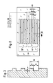
- a length measuring device 1 is shown according to the so-called three-grating incident light principle.
- the radiation from a light source L is collimated by a condenser 2 and diffracted and reflected at phase gratings A and B.
- phase grating B With phase grating B, the ratio of web width to furrow width is. 1: 1; it represents the scale grating.
- the scanning grating A is formed by two scanning fields AF and A designed as a phase grating.
- the web-groove-width ratio a: b of the scanning fields AF and A F deviates from 1: 1, which is particularly evident from FIGS. 2 and 3.
- phase gratings of the scale grating B and the scanning grating A have the same grating constant GK.
- the scale grid B and the scanning grid A are arranged parallel to one another and the scale grid B is displaceable in this parallel plane perpendicular to the course of the graduation marks.
- the radiation emanating from the light source L is diffracted by the first (scanning) grating A and the second (scale) grating B in the direction of light and reunited at the scanning grating A and brought to interference.
- the ridge / groove width ratios differ with these two grids.
- the scale grating B the ridge / groove width ratio is 1: 1, with the scanning grating it is at for example 1: 1.5. This measure leads to the fact that the diffracted partial beams of different diffraction orders are shifted in their phase relation to each other.
- the direction of the relative movement between the scanning grating A and the scale grating B can be determined from the phase-shifted partial beams which fall on the photodetectors D-1, D0, D + 1, which is indicated by the web / groove width Ratio of the scanning grating A is made possible (see FIG. 3).
- the scanning grating A is also provided with selectively acting optical means K1, K2 which, in cooperation with the two scanning fields AF and A F, enable partial beams of rays to be generated in phase opposition to the aforementioned partial beams.
- the scanning fields AF and AF are offset from one another in the measuring direction by a fraction, for example 1/4 of the lattice constants GK.
- the individual scanning fields AF or AF are assigned to prisms K2 and K1, which deflect the partial beams in opposite directions.
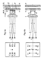
- FIG. 4a shows the position measuring device already known from FIG. 1, of which a top view is shown in FIG. 4b.
- FIG. 4b shows that the two prisms K1 and K2, which are assigned to the scanning fields AF and AF, have the partial-phase partial beams on the associated photodetectors D0 , D + 1 , D-1 and D0, D + 1, D-1 steer.
- the arrangement of the photo detectors DO , D + 1 , D-1 and D0, D + 1, D-1 each show the left part of FIGS. 4a and 4b, the focal plane of the condenser 2 being folded into the plane of the drawing. In reality, it is perpendicular to the plane of the drawing.
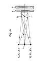
- FIG. 4c A particularly advantageous embodiment of the invention is shown in FIG. 4c, which has also been highly schematic.
- two lenses Z1 and Z2, arranged in opposite directions, become the scanning fields AF and AF assigned to collimate the light and to the corresponding photodetectors D0 , D + 1 D-1 ; Deflect D0, D + 1, D-1. Since the position of the photodetectors mentioned corresponds in principle to the illustration in FIG. 4b, a separate drawing has been omitted. Due to the arrangement of the decentred lenses Z1 and Z2 described, the condenser can be omitted.
- the selectively acting optical means can be formed by components with different spectral and / or polarization-optical properties, to which the photodetectors must of course be matched.
- the photodetectors DO and D 0 are connected antiparallel.
- a stable phase shift of 90 ° to the 0 ° signal is obtained when D + 1 is connected from the anti-parallel connection of the photo elements D + 1 and the anti-parallel interconnection of D-1 with
Landscapes
- Physics & Mathematics (AREA)
- General Physics & Mathematics (AREA)
- Optical Transform (AREA)
- Length Measuring Devices By Optical Means (AREA)
- Radar Systems Or Details Thereof (AREA)
- Transmission And Conversion Of Sensor Element Output (AREA)
Abstract
Bei dieser Positionsmeßeinrichtung (1) nach dem Dreigitter-Abtastprinzip weist das Abtastgitter (A) zwei in Meßrichtung um 1/4 der Gitterkonstante (GK) zueinander versetzte, als Phasengitter ausgebildete Abtastfelder (AF und ??) auf. Die Phasengitter der Abtastfelder (AF und ??) haben ein Steg-/Furchenbreitenverhältnis (a:b), das von 1:1 abweicht. Das Maßstabgitter (B) hat bei gleicher Gitterkonstante (GK) ein Steg-/Furchenbreiten-Verhältnis von 1:1. Mit Hilfe der durch diese Ausgestaltung des Abtastgitters (A) erzeugten, phasenverschobenen Teilstrahlenbündel läßt sich die Richtung der Relativbewegung zwischen dem Abtast- und dem Maßstabgitter (A bzw. B) bestimmen. Durch optisch gegensinnig ablenkende Prismen (K1, K2) oder dgl., die den Abtastfeldern (AF und ??) zugeordnet sind, lassen sich zu den vorgenannten phasenverschobenen Teilstrahlenbündeln weitere Teilstrahlenbündel erzeugen, die zu den vorgenannten Teilstrahlenbündeln gegenphasig sind. Allen Teilstrahlenbündeln sind eigene Photodetektoren (D0, D+1, D-1; ??, ???, ? ??) optisch zugeordnet.In this position measuring device (1) according to the three-grating scanning principle, the scanning grating (A) has two scanning fields (AF and ??) designed as phase gratings which are offset from one another by 1/4 of the grating constant (GK). The phase grids of the scanning fields (AF and ??) have a ridge / groove width ratio (a: b) which deviates from 1: 1. The scale grating (B) has a web / groove width ratio of 1: 1 with the same grating constant (GK). With the aid of the phase-shifted partial beam bundles generated by this configuration of the scanning grating (A), the direction of the relative movement between the scanning and the scale grating (A or B) can be determined. By optically deflecting prisms (K1, K2) or the like, which are assigned to the scanning fields (AF and ??), additional partial beams can be generated in addition to the aforementioned phase-shifted partial beams, which are in opposite phase to the aforementioned partial beams. Separate photodetectors (D0, D + 1, D-1; ??, ???,? ??) are optically assigned to all partial beams.
Description
Die Erfindung bezieht sich auf eine lichtelektrische Positinsmeßeinrichtung nach dem Oberbegriff des Anspruchs 1.The invention relates to a photoelectric position measuring device according to the preamble of
Positionsmeßeinrichtungen, die mit Phasengittern arbeiten, sind beispielsweise aus der DE-AS 15 48 707 und der DE-OS 23 16 248 bekannt.Position measuring devices that work with phase gratings are known for example from DE-AS 15 48 707 and DE-OS 23 16 248.
Des weiteren wird in der nicht vorveröffentlichten europäschen Patentanmeldung Nr. 85301077.5 der Anmelderin eine Positionsmeßeinrichtung beschrieben, bei der vorgeschlagen wird, eine Phasenverschiebung zwischen den am Indexgitter gebeugten Strahlenbündeln dadurch zu erzeugen, daß bei gegegener Gitterkonstante die Breite eines Steges des als Phasengitter ausgebildeten Indexgitters von der Breite einer Furche abweicht, daß also das Steg-/Furche-Verhältnis von 1:1 abweicht.Furthermore, the applicant's previously unpublished European patent application No. 85301077.5 describes a position measuring device in which it is proposed to generate a phase shift between the beams of rays diffracted at the index grating in such a way that, with the grating constant opposite, the width of a ridge of the index grating formed as a phase grating from that Width of a furrow deviates, so that the web / furrow ratio deviates from 1: 1.
Mit Hilfe der mittels eines solchen Phasengitters gewonnenen -zueinander phasenverschobenen
- -Teilstrahlenbündeln verschiedener Ordnungen kann die Richtung der. Relativverschiebung zwischen dem Maßstabgitter und dem Indexgitter ermittelt werden.
- - Partial beams of different orders can change the direction of the. Relative displacement between the scale grid and the index grid can be determined.
Die Modulationsgrade der Signale nullter und t erster Ordnung in Auflicht-Phasengittermeßsytemen mit parallel angeordnetem Index-und Maßstabgitter mit ungleich breiten Stegen bzw. Furchen des Indexgitters sind allerdings unterschiedlich und ändern sich bei Abstandsänderung, Verschmutzung des Gitters etc. ungleich.However, the degrees of modulation of the signals of zero and t first order in incident light phase grating measuring systems with parallel arranged index and scale grids with unevenly wide ridges or furrows of the index grating are different and change unevenly when the distance changes, contamination of the grating etc.
Dies ist bedingt durch das Dreigitter-Abtastprinzip und die unvermeidbare geometrisch-optische Abbildung der Lichtquelle auf den Photodetektor der nullten Ordnung.This is due to the three-grid scanning principle and the inevitable geometrical-optical imaging of the light source on the zero-order photodetector.
Die unterschiedlichen Änderungen der Modulationsgrade führen zur ungenauen und/oder unsicheren elektronischen Auswertung der Signale.The different changes in the degree of modulation lead to inaccurate and / or unsafe electronic evaluation of the signals.
Der Erfindung liegt die Aufgabe zugrunde, bei Positionsmeßeinrichtungen dieser Art die Empfindlichkeit gegenüber Abstandsänderungen, Abweichungen von der Parallelität der Gitter, Verschmutzung und dgl. zu verringern.The object of the invention is to reduce the sensitivity to changes in distance, deviations from the parallelism of the grating, contamination and the like in position measuring devices of this type.
Diese Aufgabe wird durch eine Positionsmeßeinrichtung mit den Merkmalen des Anspruchs 1 gelöst.This object is achieved by a position measuring device with the features of
Die Vorteile der erfindungsgemäßen Positionsmeßeinrichtung liegen in der einfachen Erzeugung der phasenverschobenen Abtastsignale zur Richtungserkennung in Verbindung mit der einfachen Erzeugung von Gegentaktsignalen und deren elektrischer Zusammenfassung zur Kompensation von Abtaststöreinflüssen.The advantages of the position measuring device according to the invention lie in the simple generation of the phase-shifted scanning signals for direction detection in connection with the simple generation of push-pull signals and their electrical combination for the compensation of scanning interference.
In den Unteransprüchen sind vorteilhafte Ausgestaltungen der Erfindung angegeben.Advantageous refinements of the invention are specified in the subclaims.
Mit Hilfe von Ausführungsbeispielen soll die Erfindung anhand der Zeichnungen noch näher erläutert werden, wobei die Darstellungen zum besseren Verständnis stark vereinfacht wurden.With the help of exemplary embodiments, the invention will be explained in more detail with reference to the drawings, the illustrations being greatly simplified for better understanding.
Es zeigt
Figur 1 eine schematische Darstellung einer Meßeinrichtung im Auflicht arbeitend;Figur 2 ein Abtastgitter in vergrößerter Ansicht aus Richtung II vonFigur 1;- Figur 3 ein nochmals vergrößerter Ausschnitt eines Phasengitters gemäß
Figur 2 als Fragment; - Figur 4a nochmals die Darstellung aus
Figur 1; - Figur 4b eine um 90° gedrehte Ansicht der Meßeinrichtung aus Figur 4a, mit Prismen;
- Figur 4c eine Variante der in Figur 4b dargestellten Meßeinrichtung mit dezentrierten Linsen.
- Figure 1 is a schematic representation of a measuring device working in incident light;
- Figure 2 shows a scanning grating in an enlarged view from the direction II of Figure 1;
- FIG. 3 shows a further enlarged section of a phase grating according to FIG. 2 as a fragment;
- Figure 4a again the illustration of Figure 1;
- FIG. 4b shows a view of the measuring device from FIG. 4a rotated by 90 °, with prisms;
- Figure 4c shows a variant of the measuring device shown in Figure 4b with decentered lenses.
Der im folgenden verwendete Ausdruck "Licht" umfaßt ultravoilette und infrarote Strahlung sowie die im sichtbaren Bereich liegende Strahlung.The term "light" used below includes ultraviolet and infrared radiation as well as radiation in the visible range.
In Figur 1 ist eine Längenmeßeinrichtung 1 nach dem sogenannten Dreigitter-Auflichtprinzip dargestellt. Die Strahlung einer Lichtquelle L wird von einem Kondensor 2 kollimiert und an Phasengittern A und B gebeugt und reflektiert.In Figure 1, a
Beim Phasengitter B ist das Verhältnis von Stegbreite zu Furchenbreite. 1:1; es stellt das Maßstabgitter dar. Das Abtastgitter A wird von zwei als Phasengitter ausgebildeten Abtastfeldern AF und A gebildet. Im Gegensatz zum Maßstabgitter B weicht das Steg-Furchenbreiten- Verhältnis a:b der Abtastfelder AF und A F von 1:1 ab, was besonders aus den Figuren 2 und 3 gut ersichtlich ist.With phase grating B, the ratio of web width to furrow width is. 1: 1; it represents the scale grating. The scanning grating A is formed by two scanning fields AF and A designed as a phase grating. In contrast to the scale grating B, the web-groove-width ratio a: b of the scanning fields AF and A F deviates from 1: 1, which is particularly evident from FIGS. 2 and 3.
Dabei ist zu beachten, daß die Phasengitter des Maßstabgitters B und des Abtastgitters A die gleiche Gitterkonstante GK haben. Das Maßstabgitter B und das Abtastgitter A sind parallel zueinander angeordnet und das Maßstabgitter B ist in dieser parallelen Ebene senkrecht zum Verlauf der Teilungsmarkierungen verschieblich.It should be noted that the phase gratings of the scale grating B and the scanning grating A have the same grating constant GK. The scale grid B and the scanning grid A are arranged parallel to one another and the scale grid B is displaceable in this parallel plane perpendicular to the course of the graduation marks.
Die von der Lichtquelle L ausgehende Strahlung wird von dem in Lichtrichtung ersten (Abtast)-gitter A und vom zweiten (Maßstab)-gitter B gebeugt und am Abtastgitter A wiedervereinigt und zur Interferenz gebracht.The radiation emanating from the light source L is diffracted by the first (scanning) grating A and the second (scale) grating B in the direction of light and reunited at the scanning grating A and brought to interference.
Bei gleicher Gitterkonstante GK des Maßstabgitter B und des Abstastgitters A unterscheiden sich -wie bereits erwähnt -bei diesen beiden Gittern die Steg-/Furchenbreiten-Verhältnisse. Beim Maßstabgitter B ist das Steg-/Furchenbreiten- Verhältnis 1:1, beim Abtastgitter beträgt es beispielsweise 1:1,5. Diese Maßnahme führt dazu, daß die gebeugten Teilstrahlenbündel verschiedener Beugungsordnungen in ihrer Phasenlage gegeneinander verschoben sind.With the same grating constant GK of the scale grating B and the scanning grating A, as already mentioned, the ridge / groove width ratios differ with these two grids. With the scale grating B the ridge / groove width ratio is 1: 1, with the scanning grating it is at for example 1: 1.5. This measure leads to the fact that the diffracted partial beams of different diffraction orders are shifted in their phase relation to each other.
In der Brennebene des Kondensors 2 befinden sich Photodetektoren D0, D+1, D-1 und
Aus den phasenverschobenen Teilstrahlenbündeln, die auf die Photodetektoren D-1, D0, D+1, fallen, läßt sich die Richtung der Relativbewegung zwischen dem Abtastgitter A und dem Maßstabgitter B bestimmen, was durch das von 1:1 abweichende Steg-/Furchenbreiten-Verhältnis des Abtastgitter A ermöglicht wird (s. Fig. 3).The direction of the relative movement between the scanning grating A and the scale grating B can be determined from the phase-shifted partial beams which fall on the photodetectors D-1, D0, D + 1, which is indicated by the web / groove width Ratio of the scanning grating A is made possible (see FIG. 3).
Das Abtastgitter A ist ferner mit selektiv wirkenden optischen Mitteln K1, K2 versehen, die es im Zusammenwirken mit den zwei Abtastfeldem AF und A F ermöglichen, zu den vorgenannten Teilstrahlenbündeln gegenphasige Teilstrahlenbündel zu erzeugen.The scanning grating A is also provided with selectively acting optical means K1, K2 which, in cooperation with the two scanning fields AF and A F, enable partial beams of rays to be generated in phase opposition to the aforementioned partial beams.
Die Abtastfelder AF und A F sind dazu in Meßrichtung um einen Bruchteil, beispielsweise um 1/4 der Gitterkonstate GK zueinander versetzt. Den einzelnen Abtastfeldern AF bzw.
Diese Maßnahme ist in den Figuren 4a bis 4b verdeutlicht. In Figur 4a ist dabei nochmals die aus Figur 1 bereits bekannte Positionsmeßeinrichtung dargestellt, von der in Figur 4b eine Draufsicht gezeigt ist.This measure is illustrated in Figures 4a to 4b. FIG. 4a shows the position measuring device already known from FIG. 1, of which a top view is shown in FIG. 4b.
Die Draufsicht in Figur 4b zeigt, daß die beiden Prismen K1 und K2, die den Abtastfeldem A F und AF zugeordnet sind, die gegenphasigen Teilstrahlenbündel auf die zugehörigen Photodetektoren
Eine besonders vorteilhafte Ausführungsform der Erfindung ist in Figur 4c gezeigt, die ebenfalls stark schematisiert wurde. Hier werden zwei gegensinnig dezentriert angeordnete Linsen Z1 und Z2 den Abtastfeldern
In der Auswahl der selektiv wirkenden optischen Mittel ist der Fachmann durch die aufgeführten Beispiele nicht eingeschränkt. So ist es ins Belieben des Fachmannes gestellt, daß er die Prismen oder die dezentrierten Linsen nicht gegensinnig justiert, sondem entsprechende optische Bauelemente auswählt, die zwar gleichsinnig ablenken, jedoch unterschiedliche Ablenkwinkel aufweisen. Als selektiv wirkende optische Mittel sind in diesem Sinne besonders gut Echelettegitter mit unterschiedlicher Gitterkonstante und/oder Auslenkrichtung geeignet.The person skilled in the art is not restricted in the selection of the selectively acting optical means by the examples given. Thus, it is at the discretion of the person skilled in the art that he does not adjust the prisms or the decentered lenses in opposite directions, but instead selects corresponding optical components which deflect in the same direction, but have different deflection angles. In this sense, Echelette gratings with different grating constants and / or deflection directions are particularly well suited as selective optical means.
Desgleichen können die selektiv wirkenden optischen Mittel durch Bauelemente mit unterschiedlichen spektralen und/oder polarisationsoptischen Eigenschaften gebildet werden, worauf selbstverständlich die Photodetektoren abgestimmt sein müssen.Likewise, the selectively acting optical means can be formed by components with different spectral and / or polarization-optical properties, to which the photodetectors must of course be matched.
Des weiteren liegt es im Ermessen des Fachmannes, die Techniken der Faseroptik für die Beleuchtung und die Photodetektoren anzuwenden.Furthermore, it is at the discretion of the person skilled in the art to apply the techniques of fiber optics for the lighting and the photodetectors.
Durch die geometrische Gestaltung der Abtastfelder AF und
Durch antiparalleles Zusammenschalten der Photodetektoren D + mit
Besondere Vorteile ergeben sich hinsichtlich des Wirkungsgrades, wenn die nullte Ordnung mit ausgewertet wird. Zur Erzeugung der 0°-Signales werden dazu die Photodetektoren DO und D 0 antiparallel geschaltet. Eine stabile Phasenverschiebung von 90° zum 0°-Signal erhält man, wenn aus der antiparallelen Zusammenschaltung der Photoelemente D+1 mit
Claims (7)
Priority Applications (1)
| Application Number | Priority Date | Filing Date | Title |
|---|---|---|---|
| AT86112833T ATE65839T1 (en) | 1985-11-21 | 1986-09-17 | PHOTOELECTRIC POSITION MEASUREMENT DEVICE. |
Applications Claiming Priority (2)
| Application Number | Priority Date | Filing Date | Title |
|---|---|---|---|
| DE3541199 | 1985-11-21 | ||
| DE3541199A DE3541199C1 (en) | 1985-11-21 | 1985-11-21 | Photoelectric position measuring device |
Publications (3)
| Publication Number | Publication Date |
|---|---|
| EP0223009A2 true EP0223009A2 (en) | 1987-05-27 |
| EP0223009A3 EP0223009A3 (en) | 1989-03-22 |
| EP0223009B1 EP0223009B1 (en) | 1991-07-31 |
Family
ID=6286494
Family Applications (1)
| Application Number | Title | Priority Date | Filing Date |
|---|---|---|---|
| EP86112833A Expired - Lifetime EP0223009B1 (en) | 1985-11-21 | 1986-09-17 | Opto-electronic position determination device |
Country Status (5)
| Country | Link |
|---|---|
| US (1) | US4766310A (en) |
| EP (1) | EP0223009B1 (en) |
| JP (1) | JPS62121314A (en) |
| AT (1) | ATE65839T1 (en) |
| DE (2) | DE3541199C1 (en) |
Cited By (11)
| Publication number | Priority date | Publication date | Assignee | Title |
|---|---|---|---|---|
| GB2216650A (en) * | 1988-01-22 | 1989-10-11 | Mitutoyo Corp | Optical encoder |
| GB2246430A (en) * | 1988-01-22 | 1992-01-29 | Mitutoyo Corp | Optical encoder |
| EP0509979A2 (en) * | 1991-04-18 | 1992-10-21 | RSF-Elektronik Gesellschaft m.b.H. | Photo-electronic position-measuring device |
| EP0548848A1 (en) * | 1991-12-20 | 1993-06-30 | Canon Kabushiki Kaisha | Displacement detecting device |
| US5390022A (en) * | 1992-04-07 | 1995-02-14 | Canon Kabushiki Kaisha | Displacement information detection apparatus for receiving a divergent light beam |
| US5483377A (en) * | 1992-12-24 | 1996-01-09 | Canon Kabushiki Kaisha | Displacement detection apparatus |
| EP0720005A2 (en) * | 1994-12-27 | 1996-07-03 | Canon Kabushiki Kaisha | Optical sensor |
| DE19507613A1 (en) * | 1995-03-04 | 1996-09-05 | Heidenhain Gmbh Dr Johannes | Length or angle measuring device |
| US5574559A (en) * | 1992-12-28 | 1996-11-12 | Canon Kabushiki Kaisha | Displacement detection apparatus using multiple displacement detection signals formed by a multiple phase combination grating |
| WO1998016802A1 (en) * | 1996-10-16 | 1998-04-23 | Dr. Johannes Heidenhain Gmbh | Optical position indicator |
| AT404637B (en) * | 1993-01-21 | 1999-01-25 | Rsf Elektronik Gmbh | PHOTOELECTRIC POSITION MEASURING DEVICE |
Families Citing this family (13)
| Publication number | Priority date | Publication date | Assignee | Title |
|---|---|---|---|---|
| DE8816647U1 (en) * | 1988-03-25 | 1990-02-15 | Dr. Johannes Heidenhain Gmbh, 8225 Traunreut, De | |
| DE3834676A1 (en) * | 1988-10-12 | 1990-04-19 | Heidenhain Gmbh Dr Johannes | PHOTOELECTRIC POSITION MEASURING DEVICE |
| JP2560513B2 (en) * | 1990-03-29 | 1996-12-04 | 株式会社ニコン | Diffraction interference encoder |
| DE9116546U1 (en) * | 1991-02-21 | 1993-01-21 | Dr. Johannes Heidenhain Gmbh, 8225 Traunreut, De | |
| ATE108274T1 (en) * | 1991-05-18 | 1994-07-15 | Heidenhain Gmbh Dr Johannes | INTERFERENTIAL POSITION SENSING DEVICE. |
| EP0579846B1 (en) * | 1992-07-18 | 1995-08-23 | Dr. Johannes Heidenhain GmbH | Optical device |
| JP3210111B2 (en) * | 1992-12-24 | 2001-09-17 | キヤノン株式会社 | Displacement detector |
| JP3173208B2 (en) * | 1993-01-29 | 2001-06-04 | キヤノン株式会社 | Displacement measuring device |
| DE4316250C2 (en) * | 1993-05-14 | 1997-06-12 | Heidenhain Gmbh Dr Johannes | Photoelectric length or angle measuring device |
| JPH0727543A (en) * | 1993-07-12 | 1995-01-27 | Canon Inc | Optical displacement sensor |
| JP3028716B2 (en) * | 1993-09-29 | 2000-04-04 | キヤノン株式会社 | Optical displacement sensor |
| US6005667A (en) * | 1996-07-23 | 1999-12-21 | Canon Kabushiki Kaisha | Optical displacement measurement apparatus and information recording apparatus |
| DE102006024579B4 (en) * | 2006-05-18 | 2016-09-29 | Dr. Johannes Heidenhain Gmbh | Device for determining the position of an object movable along at least one displacement direction |
Citations (6)
| Publication number | Priority date | Publication date | Assignee | Title |
|---|---|---|---|---|
| DE1084928B (en) * | 1958-06-12 | 1960-07-07 | North American Aviation Inc | Measuring device with two optical grids |
| US3482107A (en) * | 1966-07-26 | 1969-12-02 | Leitz Ernst Gmbh | Photoelectric position sensing device comprising light diffracting phase gratings using polarizer beam splitters for sensing the time phase position of the gratings |
| DE2316248A1 (en) * | 1973-03-31 | 1974-10-10 | Leitz Ernst Gmbh | PHOTOELECTRIC STEPPER |
| GB2070766A (en) * | 1980-02-27 | 1981-09-09 | Heidenhain Gmbh Dr Johannes | Photo-electric length or angle measuring apparatus |
| US4461083A (en) * | 1982-08-11 | 1984-07-24 | Dr. Johannes Heidenhain Gmbh | Length or angle measuring instrument |
| EP0163362A1 (en) * | 1984-05-31 | 1985-12-04 | Dr. Johannes Heidenhain GmbH | Displacement measuring apparatus and method |
Family Cites Families (9)
| Publication number | Priority date | Publication date | Assignee | Title |
|---|---|---|---|---|
| US3812352A (en) * | 1972-08-28 | 1974-05-21 | Itek Corp | Encoder readout system |
| GB1504691A (en) * | 1974-03-15 | 1978-03-22 | Nat Res Dev | Measurement apparatus |
| DE2714324C2 (en) * | 1977-03-31 | 1985-01-24 | Ernst Leitz Wetzlar Gmbh, 6330 Wetzlar | Photoelectric reflected-light distance measuring device |
| CH626169A5 (en) * | 1976-11-25 | 1981-10-30 | Leitz Ernst Gmbh | |
| DE2653545C2 (en) * | 1976-11-25 | 1979-01-11 | Ernst Leitz Wetzlar Gmbh, 6300 Lahn- Wetzlar | Photoelectric reflected-light distance measuring device |
| JPS5938521B2 (en) * | 1979-10-26 | 1984-09-18 | 日本電信電話株式会社 | Micro displacement measurement and alignment equipment |
| JPS5724817A (en) * | 1980-07-23 | 1982-02-09 | Yokogawa Hokushin Electric Corp | Reading device for optical type scale |
| DE3148910C1 (en) * | 1981-12-10 | 1983-03-10 | Dr. Johannes Heidenhain Gmbh, 8225 Traunreut | Photoelectric incremental length or angle measuring device |
| DE3416864C2 (en) * | 1984-05-08 | 1986-04-10 | Dr. Johannes Heidenhain Gmbh, 8225 Traunreut | Photoelectric measuring device |
-
1985
- 1985-11-21 DE DE3541199A patent/DE3541199C1/en not_active Expired
-
1986
- 1986-09-17 DE DE8686112833T patent/DE3680638D1/en not_active Expired - Fee Related
- 1986-09-17 EP EP86112833A patent/EP0223009B1/en not_active Expired - Lifetime
- 1986-09-17 AT AT86112833T patent/ATE65839T1/en not_active IP Right Cessation
- 1986-11-19 JP JP61274235A patent/JPS62121314A/en active Granted
- 1986-11-19 US US06/932,788 patent/US4766310A/en not_active Expired - Lifetime
Patent Citations (6)
| Publication number | Priority date | Publication date | Assignee | Title |
|---|---|---|---|---|
| DE1084928B (en) * | 1958-06-12 | 1960-07-07 | North American Aviation Inc | Measuring device with two optical grids |
| US3482107A (en) * | 1966-07-26 | 1969-12-02 | Leitz Ernst Gmbh | Photoelectric position sensing device comprising light diffracting phase gratings using polarizer beam splitters for sensing the time phase position of the gratings |
| DE2316248A1 (en) * | 1973-03-31 | 1974-10-10 | Leitz Ernst Gmbh | PHOTOELECTRIC STEPPER |
| GB2070766A (en) * | 1980-02-27 | 1981-09-09 | Heidenhain Gmbh Dr Johannes | Photo-electric length or angle measuring apparatus |
| US4461083A (en) * | 1982-08-11 | 1984-07-24 | Dr. Johannes Heidenhain Gmbh | Length or angle measuring instrument |
| EP0163362A1 (en) * | 1984-05-31 | 1985-12-04 | Dr. Johannes Heidenhain GmbH | Displacement measuring apparatus and method |
Non-Patent Citations (1)
| Title |
|---|
| J. WILHELM: "DREIGITTERSCGRITTGEBER", 1978, Seite 65 * |
Cited By (21)
| Publication number | Priority date | Publication date | Assignee | Title |
|---|---|---|---|---|
| GB2216650A (en) * | 1988-01-22 | 1989-10-11 | Mitutoyo Corp | Optical encoder |
| GB2246430A (en) * | 1988-01-22 | 1992-01-29 | Mitutoyo Corp | Optical encoder |
| GB2246430B (en) * | 1988-01-22 | 1992-05-13 | Mitutoyo Corp | Optical encoder |
| GB2216650B (en) * | 1988-01-22 | 1992-05-13 | Mitutoyo Corp | Optical encoder |
| EP0509979A2 (en) * | 1991-04-18 | 1992-10-21 | RSF-Elektronik Gesellschaft m.b.H. | Photo-electronic position-measuring device |
| EP0509979A3 (en) * | 1991-04-18 | 1993-01-20 | Rsf-Elektronik Gesellschaft M.B.H. | Photo-electronic position-measuring device |
| US5214280A (en) * | 1991-04-18 | 1993-05-25 | Rsf-Elektronik Gesellschaft M.B.H. | Photoelectric position detector with offset phase grating scales |
| EP0548848A1 (en) * | 1991-12-20 | 1993-06-30 | Canon Kabushiki Kaisha | Displacement detecting device |
| US5283434A (en) * | 1991-12-20 | 1994-02-01 | Canon Kabushiki Kaisha | Displacement detecting device with integral optics |
| US5390022A (en) * | 1992-04-07 | 1995-02-14 | Canon Kabushiki Kaisha | Displacement information detection apparatus for receiving a divergent light beam |
| US5483377A (en) * | 1992-12-24 | 1996-01-09 | Canon Kabushiki Kaisha | Displacement detection apparatus |
| US5574559A (en) * | 1992-12-28 | 1996-11-12 | Canon Kabushiki Kaisha | Displacement detection apparatus using multiple displacement detection signals formed by a multiple phase combination grating |
| AT404637B (en) * | 1993-01-21 | 1999-01-25 | Rsf Elektronik Gmbh | PHOTOELECTRIC POSITION MEASURING DEVICE |
| EP0720005A2 (en) * | 1994-12-27 | 1996-07-03 | Canon Kabushiki Kaisha | Optical sensor |
| EP0720005A3 (en) * | 1994-12-27 | 1997-01-15 | Canon Kk | Optical sensor |
| DE19507613A1 (en) * | 1995-03-04 | 1996-09-05 | Heidenhain Gmbh Dr Johannes | Length or angle measuring device |
| EP0731340A2 (en) * | 1995-03-04 | 1996-09-11 | Dr. Johannes Heidenhain GmbH | Length- or anglemeasuring device |
| US5678319A (en) * | 1995-03-04 | 1997-10-21 | Dr. Johannes Heidenhain Gmbh | Index grating having partial fields that are geometrically offset in the measuring direction |
| EP0731340A3 (en) * | 1995-03-04 | 1998-06-17 | Dr. Johannes Heidenhain GmbH | Length- or anglemeasuring device |
| WO1998016802A1 (en) * | 1996-10-16 | 1998-04-23 | Dr. Johannes Heidenhain Gmbh | Optical position indicator |
| US6151128A (en) * | 1996-10-16 | 2000-11-21 | Johannes Heidenhain GmbH | Optical position indicator |
Also Published As
| Publication number | Publication date |
|---|---|
| US4766310A (en) | 1988-08-23 |
| EP0223009B1 (en) | 1991-07-31 |
| EP0223009A3 (en) | 1989-03-22 |
| DE3680638D1 (en) | 1991-09-05 |
| DE3541199C1 (en) | 1987-06-25 |
| JPH0130089B2 (en) | 1989-06-16 |
| ATE65839T1 (en) | 1991-08-15 |
| JPS62121314A (en) | 1987-06-02 |
Similar Documents
| Publication | Publication Date | Title |
|---|---|---|
| EP0223009B1 (en) | Opto-electronic position determination device | |
| EP1901041B1 (en) | Position measuring device | |
| EP1923673B1 (en) | Position measuring device | |
| EP0896206B1 (en) | Read-out unit for an optical position measuring device | |
| EP0163824B1 (en) | Photoelectric measuring device | |
| EP2149036B1 (en) | Optical position measuring device | |
| EP0446691B1 (en) | Optical device | |
| DE3901869C2 (en) | Optical encoder | |
| DE102008007319A1 (en) | Optical position measuring device | |
| EP0735346A2 (en) | Opto-electrical position-measuring device | |
| EP0425726A1 (en) | Position measuring device | |
| EP0387520B1 (en) | Position-measuring installation | |
| AT404637B (en) | PHOTOELECTRIC POSITION MEASURING DEVICE | |
| EP0747674B1 (en) | Photo-electric position measuring device | |
| EP0363620A1 (en) | Photoelectrical position-measuring device | |
| DE4302313C2 (en) | Multi-coordinate measuring device | |
| EP0754933B1 (en) | Position measuring device | |
| EP1085291B1 (en) | Device for determination of positions and faults in guidance | |
| EP1028309A1 (en) | Optical encoder | |
| EP0763715A2 (en) | Device to filter overtones from signals | |
| EP2869034B1 (en) | Position sensing device | |
| DE4303162A1 (en) | Photoelectric length and angle-measuring system | |
| EP0767359A1 (en) | Photo-electrical length or angle measuring device | |
| DE19716058B4 (en) | Optical position measuring device | |
| WO2014170066A1 (en) | Device for an interferential distance measurement |
Legal Events
| Date | Code | Title | Description |
|---|---|---|---|
| PUAI | Public reference made under article 153(3) epc to a published international application that has entered the european phase |
Free format text: ORIGINAL CODE: 0009012 |
|
| 17P | Request for examination filed |
Effective date: 19861211 |
|
| AK | Designated contracting states |
Kind code of ref document: A2 Designated state(s): AT CH DE FR GB IT LI NL SE |
|
| PUAL | Search report despatched |
Free format text: ORIGINAL CODE: 0009013 |
|
| AK | Designated contracting states |
Kind code of ref document: A3 Designated state(s): AT CH DE FR GB IT LI NL SE |
|
| RAP3 | Party data changed (applicant data changed or rights of an application transferred) |
Owner name: DR. JOHANNES HEIDENHAIN GMBH |
|
| 17Q | First examination report despatched |
Effective date: 19900627 |
|
| ITF | It: translation for a ep patent filed |
Owner name: DE DOMINICIS & MAYER S.R.L. |
|
| GRAA | (expected) grant |
Free format text: ORIGINAL CODE: 0009210 |
|
| AK | Designated contracting states |
Kind code of ref document: B1 Designated state(s): AT CH DE FR GB IT LI NL SE |
|
| REF | Corresponds to: |
Ref document number: 65839 Country of ref document: AT Date of ref document: 19910815 Kind code of ref document: T |
|
| ET | Fr: translation filed | ||
| PGFP | Annual fee paid to national office [announced via postgrant information from national office to epo] |
Ref country code: CH Payment date: 19910822 Year of fee payment: 6 |
|
| PGFP | Annual fee paid to national office [announced via postgrant information from national office to epo] |
Ref country code: SE Payment date: 19910823 Year of fee payment: 6 |
|
| PGFP | Annual fee paid to national office [announced via postgrant information from national office to epo] |
Ref country code: AT Payment date: 19910826 Year of fee payment: 6 |
|
| GBT | Gb: translation of ep patent filed (gb section 77(6)(a)/1977) | ||
| REF | Corresponds to: |
Ref document number: 3680638 Country of ref document: DE Date of ref document: 19910905 |
|
| PGFP | Annual fee paid to national office [announced via postgrant information from national office to epo] |
Ref country code: NL Payment date: 19910930 Year of fee payment: 6 |
|
| PLBE | No opposition filed within time limit |
Free format text: ORIGINAL CODE: 0009261 |
|
| STAA | Information on the status of an ep patent application or granted ep patent |
Free format text: STATUS: NO OPPOSITION FILED WITHIN TIME LIMIT |
|
| 26N | No opposition filed | ||
| PG25 | Lapsed in a contracting state [announced via postgrant information from national office to epo] |
Ref country code: AT Effective date: 19920917 |
|
| PG25 | Lapsed in a contracting state [announced via postgrant information from national office to epo] |
Ref country code: SE Effective date: 19920918 |
|
| PG25 | Lapsed in a contracting state [announced via postgrant information from national office to epo] |
Ref country code: LI Effective date: 19920930 Ref country code: CH Effective date: 19920930 |
|
| PG25 | Lapsed in a contracting state [announced via postgrant information from national office to epo] |
Ref country code: NL Effective date: 19930401 |
|
| NLV4 | Nl: lapsed or anulled due to non-payment of the annual fee | ||
| REG | Reference to a national code |
Ref country code: CH Ref legal event code: PL |
|
| EUG | Se: european patent has lapsed |
Ref document number: 86112833.8 Effective date: 19930406 |
|
| REG | Reference to a national code |
Ref country code: GB Ref legal event code: IF02 |
|
| PGFP | Annual fee paid to national office [announced via postgrant information from national office to epo] |
Ref country code: GB Payment date: 20020904 Year of fee payment: 17 |
|
| PGFP | Annual fee paid to national office [announced via postgrant information from national office to epo] |
Ref country code: DE Payment date: 20020907 Year of fee payment: 17 |
|
| PGFP | Annual fee paid to national office [announced via postgrant information from national office to epo] |
Ref country code: FR Payment date: 20020909 Year of fee payment: 17 |
|
| PG25 | Lapsed in a contracting state [announced via postgrant information from national office to epo] |
Ref country code: GB Free format text: LAPSE BECAUSE OF NON-PAYMENT OF DUE FEES Effective date: 20030917 |
|
| PG25 | Lapsed in a contracting state [announced via postgrant information from national office to epo] |
Ref country code: DE Free format text: LAPSE BECAUSE OF NON-PAYMENT OF DUE FEES Effective date: 20040401 |
|
| GBPC | Gb: european patent ceased through non-payment of renewal fee |
Effective date: 20030917 |
|
| PG25 | Lapsed in a contracting state [announced via postgrant information from national office to epo] |
Ref country code: FR Free format text: LAPSE BECAUSE OF NON-PAYMENT OF DUE FEES Effective date: 20040528 |
|
| REG | Reference to a national code |
Ref country code: FR Ref legal event code: ST |
|
| PG25 | Lapsed in a contracting state [announced via postgrant information from national office to epo] |
Ref country code: IT Free format text: LAPSE BECAUSE OF NON-PAYMENT OF DUE FEES;WARNING: LAPSES OF ITALIAN PATENTS WITH EFFECTIVE DATE BEFORE 2007 MAY HAVE OCCURRED AT ANY TIME BEFORE 2007. THE CORRECT EFFECTIVE DATE MAY BE DIFFERENT FROM THE ONE RECORDED. Effective date: 20050917 |