EP0219703B1 - Improved television receiver - Google Patents
Improved television receiver Download PDFInfo
- Publication number
- EP0219703B1 EP0219703B1 EP19860113039 EP86113039A EP0219703B1 EP 0219703 B1 EP0219703 B1 EP 0219703B1 EP 19860113039 EP19860113039 EP 19860113039 EP 86113039 A EP86113039 A EP 86113039A EP 0219703 B1 EP0219703 B1 EP 0219703B1
- Authority
- EP
- European Patent Office
- Prior art keywords
- block
- tuning
- cells
- television receiver
- receiver according
- Prior art date
- Legal status (The legal status is an assumption and is not a legal conclusion. Google has not performed a legal analysis and makes no representation as to the accuracy of the status listed.)
- Expired - Lifetime
Links
Images


Classifications
-
- G—PHYSICS
- G09—EDUCATION; CRYPTOGRAPHY; DISPLAY; ADVERTISING; SEALS
- G09G—ARRANGEMENTS OR CIRCUITS FOR CONTROL OF INDICATING DEVICES USING STATIC MEANS TO PRESENT VARIABLE INFORMATION
- G09G5/00—Control arrangements or circuits for visual indicators common to cathode-ray tube indicators and other visual indicators
- G09G5/22—Control arrangements or circuits for visual indicators common to cathode-ray tube indicators and other visual indicators characterised by the display of characters or indicia using display control signals derived from coded signals representing the characters or indicia, e.g. with a character-code memory
- G09G5/222—Control of the character-code memory
-
- H—ELECTRICITY
- H03—ELECTRONIC CIRCUITRY
- H03J—TUNING RESONANT CIRCUITS; SELECTING RESONANT CIRCUITS
- H03J1/00—Details of adjusting, driving, indicating, or mechanical control arrangements for resonant circuits in general
- H03J1/0008—Details of adjusting, driving, indicating, or mechanical control arrangements for resonant circuits in general using a central processing unit, e.g. a microprocessor
- H03J1/0016—Indicating arrangements
-
- H—ELECTRICITY
- H03—ELECTRONIC CIRCUITRY
- H03J—TUNING RESONANT CIRCUITS; SELECTING RESONANT CIRCUITS
- H03J1/00—Details of adjusting, driving, indicating, or mechanical control arrangements for resonant circuits in general
- H03J1/0008—Details of adjusting, driving, indicating, or mechanical control arrangements for resonant circuits in general using a central processing unit, e.g. a microprocessor
- H03J1/0041—Details of adjusting, driving, indicating, or mechanical control arrangements for resonant circuits in general using a central processing unit, e.g. a microprocessor for frequency synthesis with counters or frequency dividers
- H03J1/005—Details of adjusting, driving, indicating, or mechanical control arrangements for resonant circuits in general using a central processing unit, e.g. a microprocessor for frequency synthesis with counters or frequency dividers in a loop
-
- H—ELECTRICITY
- H03—ELECTRONIC CIRCUITRY
- H03J—TUNING RESONANT CIRCUITS; SELECTING RESONANT CIRCUITS
- H03J5/00—Discontinuous tuning; Selecting predetermined frequencies; Selecting frequency bands with or without continuous tuning in one or more of the bands, e.g. push-button tuning, turret tuner
- H03J5/02—Discontinuous tuning; Selecting predetermined frequencies; Selecting frequency bands with or without continuous tuning in one or more of the bands, e.g. push-button tuning, turret tuner with variable tuning element having a number of predetermined settings and adjustable to a desired one of these settings
- H03J5/0245—Discontinuous tuning using an electrical variable impedance element, e.g. a voltage variable reactive diode, in which no corresponding analogue value either exists or is preset, i.e. the tuning information is only available in a digital form
- H03J5/0272—Discontinuous tuning using an electrical variable impedance element, e.g. a voltage variable reactive diode, in which no corresponding analogue value either exists or is preset, i.e. the tuning information is only available in a digital form the digital values being used to preset a counter or a frequency divider in a phase locked loop, e.g. frequency synthesizer
- H03J5/0281—Discontinuous tuning using an electrical variable impedance element, e.g. a voltage variable reactive diode, in which no corresponding analogue value either exists or is preset, i.e. the tuning information is only available in a digital form the digital values being used to preset a counter or a frequency divider in a phase locked loop, e.g. frequency synthesizer the digital values being held in an auxiliary non erasable memory
Definitions
- the present invention relates to a television receiver comprising a control unit connected to circuit means for controlling the display of alphanumerical characters, connected to television signal tuning means, to first electronic memorising means for memorising at least data relative to the tuning of said television signals, and to an operating unit for receiving data from the user.
- the known prior art television sets are designed to perform various functions (for example, the direct channel selection, the memorisation of a large number of programs, the time display, the timed turn-on or program switching, etc.) which can be easily performed with the aid of a suitably programmed microprocessor.
- Television sets may be provided with an alphanumerical character display device, for supplying data functions; for example a device comprising means for the reproduction of alphanumerical data on display screen or a printing device.
- alphanumerical character display device for supplying data functions; for example a device comprising means for the reproduction of alphanumerical data on display screen or a printing device.
- These display devices are usually only designed to provide a numerical indication of the time, channel and/or program, and the keyboard means by means of which the said functions are controlled possess a limited number of keys which cannot allow a large number of operations on the set.
- a television receiver comprising a control unit connected to circuit means for controlling the display of alphanumerical characters, connected to television signal tuning means, to first electronic memorizing means for memorizing data relative to the tuning of said television signals, and to an operating unit for receiving data from the user, characterized in that said operating unit comprise means to generate an alphanumerical set of characters, that additional groups of cells in said first electronic memorizing means are provided to memorize a plurality of alphanumerical identifying labels, each one composed of a plurality of characters, that at least one group of cells in said first memorizing means, containing said data relative to the tuning of a television signal, can be associated with a correspondent additional group of cells in said first memorizing means, containing one of said identifying labels, and that in response
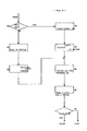
- Figure 1 shows a block diagram of a television set improved according to the present invention
- figure 2 shows a wiring diagram of some of the circuits diagrammatically shown in Fig. 1
- figures 3, 4, 5, 6, 7, 8, 9, 10, 11, 12, 13, and 14 show block diagrams of the elementary functions performed by the circuits inserted inside the television set according to the invention
- figure 15 shows a block diagram of a different embodiment of a set according to the present invention.
- reference numeral 1 indicates a remote control transmitter comprising an alphanumerical keyboard composed conveniently of 64 keys and known infrared ray transmission and coding circuits (Motorola MC 14497 integrated circuit).
- Number 2 is an infrared ray receiver circuit comprising an amplifier (Motorola TBA 2110 integrated circuit) whose output is connected to control unit 3 comprising a Fairchild 3872 integrated circuit (microcomputer).
- the control unit is also connected to :
- the character generating circuit has 3 outputs (R', G', B') connected to inputs R, G, B respectively on final video circuit 5.
- the latter also receives at inputs R, G, B the three red, green, and blue colour signals sent out from the brightness and colour circuits on the set and has three outputs connected to the cathodes of colour kinescope 6.
- Remote control transmitter 1 consists of:
- the MC 14497 integrated circuit transmits a special signal in two-phase FSK code, i.e. a series signal consisting of two packs of two given frequencies for each bit in the number of the key that has been pressed.
- Receiver amplifier circuit 2 than amplifies and demodulates the received signal into a time sequence of logic ones and zeroes. Whenever a key is released, integrated circuit MC 14497 automatically transmits an end-of-transmission code corresponding to control 63.
- Control unit 3 decodes the said time sequence into the corresponding code of the key that has been pressed. When one of the TAC, CAL or DSP function keys is pressed, the control unit switches to corresponding operating mode as described later on with reference to FIG. 3.
- control unit calls up data (scratch pad message) from memory circuits 7 and sends it to character generating circuit 4 for display on the screen, after which it prepares to receive further instructions from the transmitter, instructions which it memorises in RAM 7 for forming a new message.
- the control unit calculates the date of the first day in the month requested, draws up a seven-column table of 4 or 5 lines showing all the days in the month and sends it to character generating circuit 4.
- the calendar displayed on the screen may look like this: The month and year (DECEMBER 1980) are displayed in red, the days of the week (MO ... SA) in magenta, the numbers usually in white and "SU" and public holiday numbers (7, 14, 21, 28, 8, 25, 26) in red.
- control unit prepares for ordinary television functions (channel/programme selection, level adjustments, memorisation, etc.).
- control unit calls up tuning data relative to the selected programme number from RAM memory 7, calculates the dividing number, which it sends in code to PLL circuit 8 for tuning into the required channel, and sends the data to be displayed (selected programme/channel number, etc.) to character generating circuit 4; for certain programmes, it also supplies terminal "AV" with a time constant switch signal.
- the non-volatile RAM memory 7 or, as in the case described, the low consumption CMOS memory, with a buffer battery for preserving data even in the event of power failure, is used for memorising both scratch pad and favourite programme data in specific separate areas.
- control unit microcomputer contains a block of registers (SPAD), consisting of (64) 8-bit registers, and a RAM memory area (BUFFER), consisting of 64 RAM memory cells ranging between the FCO and FFF addresses in hexadecimal notation.
- SSD block of registers
- BAFFER RAM memory area
- DATA indicates 6 input terminals representing the ASCII code of the 64 symbols which may be displayed.
- ADD indicates 3 terminals representing the selected print line number (0-7 on 8-line display).
- DT indicates a clock terminal for moving the character forward on a given line.
- R', G', B' indicate 3 output terminals for supplying red, green and blue display picture data which is amplified and then sent to the kinescope.
- the said character generating circuit essentially consists of a Fairchild 3258 integrated circuit for generating a 64-character display matrix, a Fairchild 3529 256x8 RAM memory, a clock generator consisting of Fairchild IC10 (74LS02) and IC9 (74LS163) integrated circuits and character and line counters, for supplying addresses to the memory circuit, consisting of Fairchild IC2 (4024) and IC4 (4029) integrated circuits with the auxiliary circuits and connections shown in Fig. 2.
- the entered data is thus memorised in successive memory cells in the area set aside for the selected line.
- the character generating circuit has another two input terminals ("CS" and "OFF") - one for print enabling the character generator RAM memory and the other for disabling any printing on the screen - both connected to appropriate outputs on the microcomputer control unit. Operation of the latter is shown in the block diagrams of its basic functions.
- Fig. 3 shows reading and decoding of the controls received from amplifier 2 in Fig. 1 and function selection.
- Number 1 in Fig. 3 indicates an initialization block which, when activated by an "ON" signal, assigns specific initial values to the registers and TIMER and arranges for the "receiver control" function.
- the initialization block activates the next block (2) which reads the input signal from amplifier 2 in Fig. 1 and, in turn, activates block 3 which checks whether the signal is 0.
- the "YES” output of block 3 activates block 4 which checks whether the "DAT" register contains a preset "CROT” value.
- the "NO” output of block 4 supplies the signal for activating block 2 while the "YES” output activates block 5, which, after a set pause, supplies a "CALEN" signal for activating the blocks in Fig. 9.
- the "NO” output of block 3 activates the next block (6) which checks whether the input signal contains a START bit
- the "NO" output of block 6 supplies the signal for activating block 2 while the "YES” output of block 6 activates in turn:
- the "NO” output of block 9 supplies the signal for activating block 2, while the "YES” output activates block 10 which checks whether the "DAT" register contains a set of "FUNCTION” (code greater than 50) values.
- the "YES” output activates block 11, which arranges for the new function and memorises the content of the "DAT" register in the "FUNCTION” register, while the "NO" output of block 10 and the output of block 11 activate in turn:
- the "YES” output of block 12 supplies a "CALE” signal for activating the blocks described later in Fig. 8.
- the "YES” output of block 13 supplies a "TACC” (scratch pad) signal for activating the blocks described later in Fig. 4, while the "NO” output supplies a "STAR" signal for activating the television function control blocks described later in Fig. 11.
- Fig. 4 shows a block diagram of the basic "TACC" logic functions performed by the control unit.
- the "TACC" signal received from block 13 in Fig. 3 activates block 20 which checks whether the "DAT" register contains a prearranged "TAC” value (i.e. whether the scratch pad function key has just been pressed on keyboard 1 in Fig. 1).
- Block 23 then supplies an enabling (LOOP) control to block 2 in Fig. 3.
- the "NO” output of block 20 activates block 24, which checks whether the "DAT” register contains a prearranged “RAND” value, while the "YES” output of block 24 activates in turn:
- Blocks 30 and 32 supply the enabling signal to block 2 in Fig. 3.
- block 24 activates block 25, which, depending on the line number ("ADD" register) and pointer position ("CRT” register), sets the pointer to a particular cell in RAM memory 7 in Fig. 1.
- Block 25 activates block 33 which checks whether the content of the "DAT" register belongs to the group of control function values (greater than 50).
- the "NO" output (data for display) activates in turn:
- the "YES" output of block 36 activates in turn block 37, which sends all the line data to the character generating circuit 4, and block 38, which alters the content of the "ADD" register (line pointer).
- block 39 which sends the new line data to the character generating circuit 4 and an enabling signal to block 2 in Figs. 3.
- Fig. 5 shows the reading of a line in RAM memory 7 of Fig. 1 and transmission to the character generating circuit 4, i.e. operation of Fig. 4 blocks, such as 22, 23, 37 and 39, in greater detail.
- Number 50 in Fig. 5 indicates a block which, depending on the present line number in the "ADD" register, initialises a pointer register at a given cell on RAM memory 7 in Fig. 1.
- the said block activates in turn:
- the "NO" output of block 56 supplies an enabling signal to block 52, while the "YES” output of block 56 enables block 57, which waits for a vertical-frequency sync pulse, after which it supplies an enabling signal to block 58, which transfers the line data stored in the BUFFER to the character generating circuit 4.
- Figs 6 and 7 show block diagrams of the elementary functions performed by the microcomputer control unit for controlling composition of the printed text.
- Fig. 6 shows the page clearing functions and pointer shift with or without clearing
- Fig. 7 the shift function and pointer shift to the right or left.
- the "NO” output of block 62 supplies an enabling signal to block 63, which checks whether the "DAT" register contains a prearranged “CLEAR” value (clear key); the "YES” output activates block 64, which modifies the pointer registers to indicate the start of the next line and activates block 67, which checks whether the end of the last line has been reached; the "YES” output supplies signal “TC1" to block 21 in Fig. 4, while the "NO" output supplies an enabling signal to block 60.
- the "YES" output of block 72 activates block 73, which sets the pointers at the start of the next line, and block 74, which tr(ansmits a line of characters to the character generating circuit 4.
- the "NO" output of block 72 and block 74 supply an enabling signal to block 2 in Fig. 3.
- the "SHI” output from block 41 in Fig. 4 activates block 75, which modifies the "SHIFT” function bit (first or second function group selection on the keyboard) and supplies an enabling signal to block 74.
- the "PB" signal from block 43 in Fig. 4 activates block 76, which increases the content of counter "CRT” (pointer one place back shift), and block 77, which checks whether the pointer was positioned at the start of a line.
- CRT counter one place back shift
- the "NO” output activates block 74, while the "YES” output activates, in turn, block 78, which transmits a line of characters to the character generating circuit 4, and block 79, which sets the pointers at the end of the previous line.
- the output of block 79 supplies an enabling signal to block 74.
- the complete message recorded beforehand in the RAM appears on the screen.
- the control unit is set for compiling a new message or altering or completing the existing one.
- the pointer character "_" in the top left-hand corner indicates where any newly entered character will be inserted.
- the user may cancel the message entirely ("CLEAR" key) or shift the pointer as required for compiling the message using the pointer shift keys (back, forward, next line, etc.).
- the "SHIFT” key provides for inserting letters or numbers and punctuation marks.
- the pointer character changes to inform the user, by means of a visual aid, which group of characters has been selected ("_" for letters, "+” for numbers).
- the pointer also changes colour whenever the "COL” key is pressed (white, red, yellow, magenta) to remind the user which colour has been selected for display.
- Each character entered is automatically stored in the memory. Furthermore, whenever a key is operated (characters, pointer shift, etc.), the content of the present line is transmitted to the character generating circuit. Transmitting a whole line each time is the best compromise between transmission speed and the number of connections required and also guarantees constant character alignment.
- the scratch pad function also includes two fixed messages, generated by the control unit regardless of the message compiled by the user.
- the first concerns the more common receiver operating instructions and consists of a full page message memorised in the ROM, as opposed to the RAM, on the microcomputer during masking.
- the second corresponds to the entire group of display characters produced by the microcomputer unit (all the possible 8-bit data values displayed by the character generating circuit in 4 groups of 64 characters in 4 colours over 8 lines) which serves as a memo for the user and for making a fast check of correct circuit operation during shop testing.
- a special meaning has been assigned to the last line in the scratch pad, which may be used for memorizing special dates, such as birthdays, anniversaries, appointments, etc.
- Fig. 8 shows data entry (month and year) for the calendar call-up function.
- the "CALE” signal from block 12 in Fig. 3 activates block 80, which checks whether the "TAS" register contains a prearranged “CAL” value (i.e. whether the calendar function button has just been operated).
- the "NO” output activates, in turn, block 81, which memorises the operated key code in a cell on the RAM memory BUFFER inside the microcomputer, and block 82, which alters the content of a digit count register.
- the "YES" output of block 80 activates, in turn, block 83, which assigns an initial value to the said digit count register, and block 84, which memorises the "??/????" characters codes in the said memory buffer.
- Blocks 82 and 84 both activate:
- the "YES” output of block 87 supplies a "CALEN” signal to the blocks described later in connection with Fig. 9.
- the "NO” output supplies a signal for activating block 2 in Fig. 3 (await new data).
- Fig. 9 shows how Easter and the calendar of a given month are calculated for the set year.
- the "CALEN" signal from block 87 in Fig. 8 activates block 90, which checks whether the set month number (1-12) is acceptable; the "YES” output activates block 91, which checks whether the century number falls within a given range (16-24), while the "NO" output of blocks 90 and 91 activate in turn:
- the "YES" output of block 97 (indicating that the requested month is among the dates to be remembered) activates block 98, which memorises the number of the day to be remembered in a "SPAD" register.
- Block 98 and the "NO" output of block 97 activate block 99, which checks whether the date to be remembered is the last one in the RAM memory.
- the latter shows block diagrams of elementary logic functions performed by the control unit for displaying a calendar page.
- the "DSP" signal from block 99 in Fig. 9 activates block 100, which sets the colour yellow and activates block 101, which checks whether it is the first line.
- the "YES" output of block 101 (line containing the name of the month and the year) activates in turn:
- the output of block 106 supplies a signal for activating block 101, the "NO" output of block 101 activates block 107, which checks whether it is the second line.
- the "YES” output of block 107 (line containing abbreviations of the days of the week: MO, TU, WE, TH, FR, SA, SU) activates block 108, which sets the colour magenta, and block 109, which checks whether it is the last column.
- the "YES” output (Sundays) activates block 110, which sets the colour red, while the "NO" output and the output of block 110 activate, in turn, block 111, which sends 2 data from the ROM and 2 blanks to the character generating circuit 4, and block 112, which checks whether it is the end of a line.
- the "NO” output of block 112 supplies an enabling signal to block 109, while the "YES” output of block 112 activates in turn:
- the "NO" output of block 128 (incomplete calendar page) supplies a signal for activating block 101, while the "YES” output of block 128 (complete page; increment month and year for rotating calendar) activates block 129, which checks whether the number of the month is 12.
- the "NO" output of block 129 activates block 131, which increments the number of the month, while the "YES” output activates block 130, which assigns a 1 to the number of the month and increments the number of the year.
- the outputs of blocks 130 and 131 supply a signal for activating block 2 in Fig. 3 (end of calendar, await new instructions; if the "CROT" key has been pressed, after a certain length of time, the "CALEN” signal is generated again and the next month's calendar displayed on the screen).
- the "NO" output of block 120 activates block 121, which sets the colour red.
- Blocks 119 and 121 and the "NO" output of block 120 activate, in turn, block 122, which sends "DATA" relative to the day of the month and 2 blanks to the character generating circuit 4, and block 123, which checks whether the date corresponds with the length of the month.
- block 123 activates block 124, which assigns the "DATA" a blank code (to fill in with blanks after the last day of the month).
- Block 124 and the "NO" output of block 123 activate block 125, which checks whether it is the end of a line.
- the "NO” output activates block 117, while the "YES” output activates block 126.
- Fig. 11 shows operation mode selection (favourite programme selection, memorisation, etc.), "SHIFT" and memory page switch functions, return to normal television operation and memorisation of programme-associated station labels.
- the "STAR" signal in Fig. 11 from block 13 in Fig. 3 activates block 130 which checks whether the operated key corresponds to a preset "DSP" code (return to normal operation of the set).
- block 150 which checks whether, instead of the key number, the buffer contains the "?" code.
- the "YES" output of block 150 activates block 151, which recovers the key number from one of the internal "SPAD” registers.
- the "YES” output of block 152 activates block 154, which clears the label in the buffer.
- the "YES” output of block 153 activates block 155, which recovers the channel number from the "SPAD”.
- the outputs of blocks 151 and 154 and the "NO" output of block 153 activate block 156, which checks whether the key number is between 0 and 9.
- the "YES” output supplies an "INDIR” signal to the blocks in Fig. 13, while the "NO” output and the output of block 155 supply a "DIRET” signal to the next receiver blocks for selecting a station in the usual way on the basis of a given transmission standard channel number.
- the "NO" output of block 130 activates block 131, which checks whether the operated key corresponds to a given "SHIFT" code.
- Block 131 activates block 133, which checks whether the "SHIFT” function is 1; the "YES” output activates block 134, which zeroes the bit, while the "NO” output activates block 135, which sets the bit to 1.
- Blocks 134 and 135 supply a signal for activating block 163, which transmits the words "CHANNEL” and "KEY” to the character generating circuit 4 together with the memory page, channel and programme numbers and a label, if there is one.
- a typical display in this case is:
- the "NO" output of block 131 activates block 132, which checks whether the operated key corresponds to a given "PAG" code.
- block 132 activates, in turn, block 136, which increments the page number within a 1-3 range, block 137, which memorises the page number in the buffer, and display block 163.
- the "NO" output of block 132 activates block 138, which checks whether the operated key corresponds to a given "PRG" code.
- the "YES” output of block 138 activates block 139, which checks whether the operated key corresponds to a code from 11-13; the "YES” output supplies a "FINET” signal to the next blocks on the set, which perform a tuning correction, while the "NO” output activates, in turn, block 140, which saves the operated key in a "MOO” register, and block 141, which checks whether the "MOO" register contains a prearranged 19 code.
- the "YES” output of block 141 supplies a "MEMOR” signal to the blocks in Fig. 12, while the “NO” output supplies an enable signal to block 142, which checks whether the "MOO" register contains a prearranged code 48.
- the "YES” output supplies a "PRG” signal to the blocks in Fig. 14, while the “NO” output supplies a signal to the next blocks in Fig. 13.
- the "YES” output of block 146 activates block 147, which saves the operated number in the buffer and supplies an enabling signal to block 141.
- "YES” output of block 145, 148 and 149 supply an enabling signal to block 139.
- the "NO” output of block 149 supplies a "RICER” signal to the next blocks on the set which automatically scan the memorised programmes and receivable channels.
- Block 162 supplies a signal for activating display block 163 and for generating the "LOOP" signal for awaiting new instructions.
- Fig. 12 shows map display of the channels on a memory page and memorisation of channel data for assigning it to a given key.
- the "MEMOR” signal from block 141 in Fig. 11 activates block 170, which checks whether the operated key corresponds to a preset "MEM” value (memorisation button).
- block 173 activates block 174, which reads the tuning, colour, volume and brightness data from the RAM memory and memorises it in four "SPAD" registers.
- Block 174 and the "YES" output of block 173 activate, in turn, block 175, which reads the channel number from the RAM memory and memorises it in the "RD" register, and block 176, which checks whether the read data is acceptable.
- the "NO” output of block 176 activates block 177, which assigns a fictitious "FF" number to the channel, while the output of block 177 and the "YES” output of block 176 activate, in turn:
- the "NO” output of block 180 activates block 181, which assigns an "FF" number to the channel, while the "YES” output activates block 182, which memorises the label data in the buffer.
- Blocks 181 and 182 activate, in turn, block 183, which memorises the channel number in the "SPAD”, and block 184, which checks whether the key count register contains a zero.
- the "NO” output of block 184 supplies a signal for activating block 172, while the "YES” output supplies a signal for activating block 185, which sends the number of 10 channels on a given memory page to the character generating circuit 4 for displaying the map.
- a typical channel map display is: which indicates that the third program page contains channels C, 21, 30, 42, 22, 35 and 61 associated to keys 0-6, while keys 7, 8 and 9 are unassigned.
- Blocks 172 to 177 form a single block, which we shall call “READ”, for reading all the programme data from the RAM memory.
- Blocks 178-182 also form a single block, which we shall call “ET1”, for reading the label data from the RAM memory.
- the "NO" output of block 170 activates block 186, which checks whether the operated key corresponds to a number from 0 to 9.
- the "NO” output (second time the "MEM” key has been operated) activates, in turn, block 187, which clears the previous label in the buffer, and block 188, which checks whether the channel number is acceptable.
- the "YES” output of block 188 activates block 190, which memorises an "?" in the buffer to show the receiver is waiting for the key number to be memorised, while the "NO" output activates block 189, which supplies an error signal to block 2 in Fig. 3 (await further instructions).
- Block 198 supplies a signal for activating block 163 in Fig. 11 (await three label characters) which are then memorised when blocks 157-162 in Fig. 11 (PET) are activated.
- a typical display during label memorisation is:
- each label consists of three characters which may be letters of the alphabet, numbers or blanks.
- a special significance has been assigned, however, to labels whose first two letters are "VC", i.e. "VCR".
- these labels which recall the video cassette recorder, cause the microcomputer control unit to activate an automatic "AV" (time constant) switch so as to provide for good picture stability in case of signals supplied from a video cassette recorder.
- the "AV" switch activating function has been assigned to all the labels beginning with the letters "VC”, so that switching is performed automatically both in case of a "VCR” label, associated with a video cassette recorder, and "VC1", “VC2”, “VCX” labels, etc. for receiving a number of different stations with a switched time constant, e.g. private broadcasting stations, using commercial video cassette recorders.
- Fig. 13 shows indirect programme selection, i.e. tuning into the 10x3 preferred stations corresponding to each of the 10 keys on the three pages.
- the "INDIR" signal fromm the Fig. 11 blocks activates block 200, which provides for normal display and indirect call-up mode, and block 201, which checks whether the operated key corresponds to a number from 0 to 9.
- the "YES" output of block 201 activates, in turn, block 202, which calculates the time interval between two number key operations, and block 203, which checks whether the interval is greater than a given length of time, i.e. one second.
- the "NO" output of block 203 (two numbers operated in less than one second) supplies a "DIRET" signal to the next blocks on the receiver for selecting the station on the basis of the channel number, while the "YES” output of block 203 and the "NO” output of block 201 activate, in turn:
- Blocks 212, 216 and 217 activate block 163 in Fig. 11 for display and awaiting further instructions.
- Fig. 14 shows selection of a station using the label associated with it.
- the "PRG” signal from block 142 in Fig. 11 activates block 220, which checks whether the operated key corresponds to a preset "PRGM” code.
- the "YES” output of block 220 (first time the "PRG” key is operated) activates, in turn:
- Block 224 and the "NO" output of block 226 supply a signal for activating block 163 in Fig. 11 (await new data display).
- Block 233 supplies a signal for activating block 200 in Fig. 13.
- the "NO” output of block 230 activates, in turn, block 234, which decreases the key number, and block 235, which checks whether the key number is less than zero.
- the "NO" output supplies a signal for activating block 229, while the "YES” output activates, in turn, block 236, which decreases the page number, and block 237, which checks whether the page number is equal to zero.
- the "NO" output of block 237 (label not yet found among the 10 memorised programmes) supplies a signal for activating block 238, while the "YES” output (label not in the memory) supplies a signal for activating block 221 and the next ones (new label setting).
- the "receiver control" function is selected automatically when the set is turned on (block 1 in Fig. 3) or the "DSP" key is pressed.
- Memorised programmes are divided into three 10- programme pages, each programme indicated by 5 data and 3 letters for the label if there is one.
- the said data is stored in the memory in consecutive blocks of 5 (programme 0 page 1, programme 1 page 1, ..., programme 9 page 3, label 0 page 1, ..., label 9 page 3).
- the microcomputer is used for performing a considerable number of functions, besides the control of the typical functions of the television receiver, so that its use is rendered optimal from the point of view of the cost/performance ratio.
- variants may consist in the selection of other colours for the writings, in particular in the case of the calendar, or in the choice of a different mode of presentation of the calendar (for example, more months at the same time), or in the use of labels comprising a different number of characters in the case of the selection of a program by menas of the mnemonic label.
- reference numeral 8 in Fig. 1 indicates a frequency-synthesis circuit of the PLL type for obtaining the tuning for a television receiver.
- the invention may be used advantageously also in an electronic tuning circuit with memorisation of the voltage-synthesis type, in which each selected station has associated thereto and memorised a voltage in the form of a binary number which is then converted in a D/A converter into a tuning voltage to be applied to the variable reactance circuit contained in the tuning unit of the receiver. Therefore, the devices which obtain the memorisation of the said binary number may conveniently be dimensioned in such a manner as to contain also data relative to the labels to be associated to each memorised program.
- Another variant may consist in displaying, besides the map of the memorised channels, also the map of the labels associated to the memorised channels.
- a block similar to block 183 memorises in particular inner registers the codes relative to the characters forming the labels, instead of the channel number.
- the remote control unit 1 provided with the alphanumerical keyboard and the receiver circuit 2, the control unit 3, the memory 7, eventually the circuit 8 and the character generating circuit 4 and the final video circuit 5, conveniently modified, may be designed not only for a colour type television set having the characteristics described hereinabove, but also for a colour television set having different functions, and eventually also for a black and white television set and generally for any device provided with a display screen, usable not only as described hereinabove, but also, in an exclusive or differently combinatorial manner, as note-book, calendar, etc., and generally as a device for displaying on a screen (of any type) pictures formed by alphanumerical characters.
- a receiver of radioelectric signals in general may be mentioned, in which it is possible to receive stations emitting on pre-established frequencies, by simply requesting the menemonic label formed by some alphanumerical characters which has been memorised in association with the said station, according to the same principle which has already been described for the selection of television channels.
- the character generator 4 or a character generator of a different, more simplified type, controls directly an alphanumerical character display device for the presentation of the said mnemonic labels.
- the selection of the preferred and previously memorised stations may take place by sending to the control unit 3 the code corresponding to the selected mnemonic label, either by means of the keyboard of the remote-control unit 1 , or by means of a keyboard connected directly to the control unit 3.
- the variant shown in Fig. 15 relates to a set comprising reproducer means for the reproduction of alphanumerical data, on a display screen, or reproducer printing means or vocal reproducer means, and in respect of the block diagram shown in Fig. 1 there is missing the frequency-synthesis PLL circuit 8.
- the circuit 4 (which is a known circuit for the reproducer means 5) receives the signals from the control unit 3 and generates the pilot control signals for the reproducer means 5 which reproduce on a screen, or printing reproducers (or vocal reproducers), so as to obtain the 64 types of alphanumerical characters corresponding to the 64 keys which may be selevcted by means of the keyboard of the transmitter 1.
- the operation of the set shown in Fig. 15 may be inferred from what has been described in the foregoing.
- the apparatus shown in Fig. 1 may be used for different functions, including also tn note-book function for memorizing determined data and reproducing them at the desired moment, or the calendar function for obtaining data of the type described already in the foregoing, with the advantage of having the control keyboard 1 freely movable, without to be constrained to a fixed and limited position relative to the set.
Description
- The present invention relates to a television receiver comprising a control unit connected to circuit means for controlling the display of alphanumerical characters, connected to television signal tuning means, to first electronic memorising means for memorising at least data relative to the tuning of said television signals, and to an operating unit for receiving data from the user.
- The known prior art television sets are designed to perform various functions (for example, the direct channel selection, the memorisation of a large number of programs, the time display, the timed turn-on or program switching, etc.) which can be easily performed with the aid of a suitably programmed microprocessor.
- Television sets (see for example US-A-4270145) may be provided with an alphanumerical character display device, for supplying data functions; for example a device comprising means for the reproduction of alphanumerical data on display screen or a printing device. These display devices are usually only designed to provide a numerical indication of the time, channel and/or program, and the keyboard means by means of which the said functions are controlled possess a limited number of keys which cannot allow a large number of operations on the set.
- It is also known, for example by the published German Patent Application DE-A-2 911 102, to use a television receiver, together with a keyboard, a telephone set, a data Bank or a computer, to retrieve data from a suitable data source.
- The object of the present invention is to provide a television set which could perform more sophisticated functions than the prior art comparable sets, with no substantial increase in the complexity and cost of the circuits, functions which normally could be obtained only at a major cost by means of computers. Therefore, on the ground of the present invention there is provided a television receiver comprising a control unit connected to circuit means for controlling the display of alphanumerical characters, connected to television signal tuning means, to first electronic memorizing means for memorizing data relative to the tuning of said television signals, and to an operating unit for receiving data from the user, characterized in that said operating unit comprise means to generate an alphanumerical set of characters, that additional groups of cells in said first electronic memorizing means are provided to memorize a plurality of alphanumerical identifying labels, each one composed of a plurality of characters, that at least one group of cells in said first memorizing means, containing said data relative to the tuning of a television signal, can be associated with a correspondent additional group of cells in said first memorizing means, containing one of said identifying labels, and that in response to a first coded control signal coming from said operating unit and corresponding to one of said identifying labels, the said control unit searches said additional groups of cells in said first memorizing means and extracts from the corresponding one group of cells the data relative to the tuning of said television signal and sends them to the said tuning means, in order to correctly tune the said station, and supplies the said circuit means with codes apt to obtain the display of the said identifying label.
- The invention will now be described in detail, in order to render easy its realization, in particular with reference to the annexed drawings given by way of non-limiting example.
- Figure 1 shows a block diagram of a television set improved according to the present invention; figure 2 shows a wiring diagram of some of the circuits diagrammatically shown in Fig. 1; figures 3, 4, 5, 6, 7, 8, 9, 10, 11, 12, 13, and 14 show block diagrams of the elementary functions performed by the circuits inserted inside the television set according to the invention and figure 15 shows a block diagram of a different embodiment of a set according to the present invention.
- In Fig. 1,
reference numeral 1 indicates a remote control transmitter comprising an alphanumerical keyboard composed conveniently of 64 keys and known infrared ray transmission and coding circuits (Motorola MC 14497 integrated circuit).Number 2 is an infrared ray receiver circuit comprising an amplifier (Motorola TBA 2110 integrated circuit) whose output is connected tocontrol unit 3 comprising a Fairchild 3872 integrated circuit (microcomputer). - The control unit is also connected to :
- a RAM CMOS memory (7) consisting of 512 8-bits-cells and made using two RCA MW 5113 512x4 RAM memories;
- a PLL frequency synthesis circuit (8) for direct channel tuning consisting of a Motorola UAA 2000 integrated circuit;
- a character generating circuit (4) for displaying 64 types of alphanumerical characters on the screen with a 5x7 dot matrix, arranged in 8 lines of 32 characters each;
- the "AV" terminal of a known time constant switch circuit for the line sync circuits on the receiver.
- The character generating circuit has 3 outputs (R', G', B') connected to inputs R, G, B respectively on
final video circuit 5. The latter also receives at inputs R, G, B the three red, green, and blue colour signals sent out from the brightness and colour circuits on the set and has three outputs connected to the cathodes ofcolour kinescope 6. - More detailed information about the integrated and associated operating circuits mentioned above and later on can be found in the maker's specifications and catalogues which are readily available on the market.
- Operation of the circuit is as follows:
Remote control transmitter 1 consists of: - a first set of 32 dual function buttons, the first or second function being selected by means of a "shift" key; the first set of functions includes the letters of the alphabet and the second the numbers and punctuation marks;
- three keys TAC, CAL, DSP for selecting the required function: scratch pad, calendar, return to normal receiver functions control;
- eight control keys for compiling the scratch pad message;
- an OFF key for switching the set off.
- When any one of these 44 keys is pressed, the MC 14497 integrated circuit transmits a special signal in two-phase FSK code, i.e. a series signal consisting of two packs of two given frequencies for each bit in the number of the key that has been pressed. Receiver
amplifier circuit 2 than amplifies and demodulates the received signal into a time sequence of logic ones and zeroes. Whenever a key is released, integrated circuit MC 14497 automatically transmits an end-of-transmission code corresponding tocontrol 63. -
Control unit 3 decodes the said time sequence into the corresponding code of the key that has been pressed. When one of the TAC, CAL or DSP function keys is pressed, the control unit switches to corresponding operating mode as described later on with reference to FIG. 3. - If the TAC key is pressed, the control unit calls up data (scratch pad message) from
memory circuits 7 and sends it tocharacter generating circuit 4 for display on the screen, after which it prepares to receive further instructions from the transmitter, instructions which it memorises inRAM 7 for forming a new message. - More details will be given about this when we get to Figs 4, 5, 6 and 7.
- If the CAL button is pressed, the control unit sends
character generating circuit 4 the following message:
"CALENDAR OF ??/????"
and prepares to receive the number of the month (January = 01, December = 12) and calendar year in question. Once this data has been supplied, the control unit calculates the date of the first day in the month requested, draws up a seven-column table of 4 or 5 lines showing all the days in the month and sends it tocharacter generating circuit 4. The calendar displayed on the screen may look like this:
The month and year (DECEMBER 1980) are displayed in red, the days of the week (MO ... SA) in magenta, the numbers usually in white and "SU" and public holiday numbers (7, 14, 21, 28, 8, 25, 26) in red. - More detailes about this will be given later when we get to Figs 8, 9 and 10.
- If the DSP button is pressed, the control unit prepares for ordinary television functions (channel/programme selection, level adjustments, memorisation, etc.).
- In the case of programme selection, for example, the control unit calls up tuning data relative to the selected programme number from
RAM memory 7, calculates the dividing number, which it sends in code toPLL circuit 8 for tuning into the required channel, and sends the data to be displayed (selected programme/channel number, etc.) tocharacter generating circuit 4; for certain programmes, it also supplies terminal "AV" with a time constant switch signal. - The way some of these functions are controlled by the present invention will be described in more detail when we get to Figs 11, 12, 13 and 14, particularly as regards memory labels for identifying priority stations.
- The
non-volatile RAM memory 7 or, as in the case described, the low consumption CMOS memory, with a buffer battery for preserving data even in the event of power failure, is used for memorising both scratch pad and favourite programme data in specific separate areas. Scratch pad data in 32x8 = 256 cells, i.e. the first half of the memory and programme data in 8x10x3 =240 cells (8 data per programme on 3x10 = 30 programmes in 3 pages of 10) in the second half of the memory. Besides theexternal RAM memory 7, the control unit microcomputer contains a block of registers (SPAD), consisting of (64) 8-bit registers, and a RAM memory area (BUFFER), consisting of 64 RAM memory cells ranging between the FCO and FFF addresses in hexadecimal notation. - Operation of
character generating circuit 4, connected tokinescope 6 via finalvideo amplifier circuit 5, will now be described with reference to Fig. 2.
"DATA" indicates 6 input terminals representing the ASCII code of the 64 symbols which may be displayed.
"COLOUR" indicates 2 terminals representing the particolar colour assigned to each character (00 = RED, 10=YELLOW, 01 = MAGENTA, 11 = WHITE).
"ADD" indicates 3 terminals representing the selected print line number (0-7 on 8-line display).
"DT" indicates a clock terminal for moving the character forward on a given line.
"FH" and "FV" indicate 2 sync terminals, one horizontal- and the other vertical-frequency, depending on the scanning of the set.
"R', G', B'" indicate 3 output terminals for supplying red, green and blue display picture data which is amplified and then sent to the kinescope. - The said character generating circuit essentially consists of a Fairchild 3258 integrated circuit for generating a 64-character display matrix, a Fairchild 3529 256x8 RAM memory, a clock generator consisting of Fairchild IC10 (74LS02) and IC9 (74LS163) integrated circuits and character and line counters, for supplying addresses to the memory circuit, consisting of Fairchild IC2 (4024) and IC4 (4029) integrated circuits with the auxiliary circuits and connections shown in Fig. 2.
- Operation of the circuit is as follows:
For printing on a given line, the line number must first be sent to the "ADD" terminals so as to set the line counter to the required value. A signal is then sent to the "DT" terminal for setting the memory to print mode, followed by the display character and clock pulse which are sent respectively to the "DATA", "COLOUR" and "DC" terminals. - The entered data is thus memorised in successive memory cells in the area set aside for the selected line.
- The above operation is repeated in the case of multiple lines and, once all the data has been loaded, the characters stored in the memory are displayed by removing the signal on the "DT" terminal.
- This causes the cells on the RAM memory to be scanned, in time with the vertical- and horizontal-frequency signals on the set, the content of which (6 bits corresponding to the ASCII code of the character in question) is sent to the input of character generating
integrated circuit 3258. This then sends out 5 signals, corresponding to the 5 picture elements making up a line on the 5x7 character matrix, which are converted into a series signal by the parallel-series converter, consisting of a Fairchild IC8 (74LS165) integrated circuit, which is then sent to one or more of outputs R', G', B' depending on the two colour bits. - The character generating circuit has another two input terminals ("CS" and "OFF") - one for print enabling the character generator RAM memory and the other for disabling any printing on the screen - both connected to appropriate outputs on the microcomputer control unit.
Operation of the latter is shown in the block diagrams of its basic functions. - Fig. 3 shows reading and decoding of the controls received from
amplifier 2 in Fig. 1 and function selection.Number 1 in Fig. 3 indicates an initialization block which, when activated by an "ON" signal, assigns specific initial values to the registers and TIMER and arranges for the "receiver control" function. - The initialization block activates the next block (2) which reads the input signal from
amplifier 2 in Fig. 1 and, in turn, activatesblock 3 which checks whether the signal is 0.
The "YES" output ofblock 3 activatesblock 4 which checks whether the "DAT" register contains a preset "CROT" value.
The "NO" output ofblock 4 supplies the signal for activatingblock 2 while the "YES" output activatesblock 5, which, after a set pause, supplies a "CALEN" signal for activating the blocks in Fig. 9. - The "NO" output of
block 3 activates the next block (6) which checks whether the input signal contains a START bit The "NO" output ofblock 6 supplies the signal for activatingblock 2 while the "YES" output ofblock 6 activates in turn: -
block 7 which reads the series signal received fromamplifier 2 in Fig. 1; -
block 8 which converts the read data into a binary number and memorises it in the "DAT" register; -
block 9 which detects the presence of an end-of-transmission signal ("EOT"). - The "NO" output of
block 9 supplies the signal for activatingblock 2, while the "YES" output activatesblock 10 which checks whether the "DAT" register contains a set of "FUNCTION" (code greater than 50) values. The "YES" output activatesblock 11, which arranges for the new function and memorises the content of the "DAT" register in the "FUNCTION" register, while the "NO" output ofblock 10 and the output ofblock 11 activate in turn: -
block 12 which checks whether the "FUNCTION" register contains a prearranged "CAL" value corresponding to the code of the calendar key onkeyboard 1 in Fig. 2; -
block 13 which checks whether the "FUNCTION" register contains a prearranged "TAC" value corresponding to the code of the scratch pad key onkeyboard 1 in Fig. 2. - The "YES" output of
block 12 supplies a "CALE" signal for activating the blocks described later in Fig. 8. The "YES" output ofblock 13 supplies a "TACC" (scratch pad) signal for activating the blocks described later in Fig. 4, while the "NO" output supplies a "STAR" signal for activating the television function control blocks described later in Fig. 11. - Fig. 4 shows a block diagram of the basic "TACC" logic functions performed by the control unit.
- The "TACC" signal received from
block 13 in Fig. 3 activatesblock 20 which checks whether the "DAT" register contains a prearranged "TAC" value (i.e. whether the scratch pad function key has just been pressed onkeyboard 1 in Fig. 1). - The "YES" output (first time) activates in turn:
-
block 21 which zeroes the shift mode (sets the keys in the first character group, i.e. letters of the alphabet); -
block 22 which suppliescharacter generating circuit 4 in Fig. 1 with the data stored inRAM memory 7 in Fig. 1 corresponding to the last 7 lines of characters forming the scratch pad message; -
block 23 which supplies thecharacter generating circuit 4 with first line data and positions the "pointer" character in the first top left-hand position on the screen. -
Block 23 then supplies an enabling (LOOP) control to block 2 in Fig. 3. The "NO" output ofblock 20 activatesblock 24, which checks whether the "DAT" register contains a prearranged "RAND" value, while the "YES" output ofblock 24 activates in turn: -
block 26, which sets a pointer at the start of the message in the form of a set of codes stored in the ROM memory on the microcomputer; -
block 27 which checks for an "F" signal. - The "YES" output of
block 27 then activates block 31 which clears the "F" signal and block 32 which sends the ROM code sequence to thecharacter generating circuit 4. - The "NO" output of
block 27 activates in turn: -
block 28 which generates the "F" signal; -
block 29 which generates all the codes representing all the characters that can be generated by thecharacter generating circuit 4; -
block 30 which sends the generated codes to thecharacter generating circuit 4. -
Blocks - The "NO" output of
block 24 activatesblock 25, which, depending on the line number ("ADD" register) and pointer position ("CRT" register), sets the pointer to a particular cell inRAM memory 7 in Fig. 1. -
Block 25 activatesblock 33 which checks whether the content of the "DAT" register belongs to the group of control function values (greater than 50). - The "NO" output (data for display) activates in turn:
-
block 34, which adds a shift function bit and two colour bits to the content of the "DAT" register and memorises the new data in the RAM memory; -
block 35, which alters the content of the "CRT" register (pointer position); -
block 36, which checks whether the position of the pointer corresponds to the end of a line. - The "YES" output of
block 36 activates inturn block 37, which sends all the line data to thecharacter generating circuit 4, and block 38, which alters the content of the "ADD" register (line pointer). - The "NO" output of
block 36 and block 38 activate block 39, which sends the new line data to thecharacter generating circuit 4 and an enabling signal to block 2 in Figs. 3. - The "YES" output of
block 33 activates in turn: -
block 40, which checks whether the "DAT" register contains a prearranged "RETURN" value (new line key clearing all the remaining characters on the present line); -
block 41, which checks whether the "DAT" register contains a prearranged "SHIFT" value (key for selecting first or second case for the first 32 keys on the keyboard); -
block 42, which checks whether the "DAT" register contains a prearranged "PFOR" value (pointer forward shift key); -
block 43, which checks whether the "DAT" register contains a prearranged "PBACK" value (pointer backward shift key); -
block 44, which checks whether the "DAT" register contains a prearranged "PDOWN" value (key for shifting the pointer to the start of the next line); -
block 45, which checks whether the "DAT" register contains a prearranged "CLEAR" value (key for clearing the page starting from the present position); - block 46, which alters the data (0-3) in the colour register.
- The "YES" outputs of
blocks - Fig. 5 shows the reading of a line in
RAM memory 7 of Fig. 1 and transmission to thecharacter generating circuit 4, i.e. operation of Fig. 4 blocks, such as 22, 23, 37 and 39, in greater detail. -
Number 50 in Fig. 5 indicates a block which, depending on the present line number in the "ADD" register, initialises a pointer register at a given cell onRAM memory 7 in Fig. 1. - The said block activates in turn:
-
block 51, which enables the RAM memory for reading; -
block 52, which reads data from the said memory; -
block 53, which checks whether the position of the character that has just been read tallies with the position of the pointer. - The "YES" output of
block 53 activatesblock 54, which substitutes the read data with a selected pointed character code ("_" = 31) and adds the colour and shift bits. - The "NO" output of
block 53 and the ouput ofblock 54 activate in turn: -
block 55, which copies the data into a memory BUFFER inside the microcomputer control unit; -
block 56, which checks whether the read data is the last of a print line. - The "NO" output of
block 56 supplies an enabling signal to block 52, while the "YES" output ofblock 56 enablesblock 57, which waits for a vertical-frequency sync pulse, after which it supplies an enabling signal to block 58, which transfers the line data stored in the BUFFER to thecharacter generating circuit 4. - Figs 6 and 7 show block diagrams of the elementary functions performed by the microcomputer control unit for controlling composition of the printed text.
- Fig. 6 shows the page clearing functions and pointer shift with or without clearing and Fig. 7 the shift function and pointer shift to the right or left.
- The "RET" or "CL" signal in Fig. 6, supplied by
blocks -
block 60, which sends the "BLANK" character code toRAM memory 7 in Fig. 1; -
block 61, which modifies pointer position counter "CRT"; -
block 62, which checks whether the position corresponds with the end of a line. - The "NO" output of
block 62 supplies an enabling signal to block 63, which checks whether the "DAT" register contains a prearranged "CLEAR" value (clear key); the "YES" output activatesblock 64, which modifies the pointer registers to indicate the start of the next line and activatesblock 67, which checks whether the end of the last line has been reached; the "YES" output supplies signal "TC1" to block 21 in Fig. 4, while the "NO" output supplies an enabling signal to block 60. - The "NO" output activates in turn:
-
block 65, which transmits a line of data to thecharacter generating circuit 4; -
block 66, which points to the start of the next line and supplies an enabling signal to block 2 in Fig. 3 (await new data). - The "PF" signal in Fig. 7 from
block 42 in Fig. 4 activates in turn: -
block 70, which decreases the "CRT" register (one place forward pointer shift); -
block 71, which transmits a line of characters to thecharacter generating circuit 4; -
block 72, which checks whether the pointer is positioned at the end of a line. - The "YES" output of
block 72 activatesblock 73, which sets the pointers at the start of the next line, and block 74, which tr(ansmits a line of characters to thecharacter generating circuit 4. - The "NO" output of
block 72 and block 74 supply an enabling signal to block 2 in Fig. 3. The "SHI" output fromblock 41 in Fig. 4 activatesblock 75, which modifies the "SHIFT" function bit (first or second function group selection on the keyboard) and supplies an enabling signal to block 74. - The "PB" signal from
block 43 in Fig. 4 activatesblock 76, which increases the content of counter "CRT" (pointer one place back shift), and block 77, which checks whether the pointer was positioned at the start of a line. - The "NO" output activates
block 74, while the "YES" output activates, in turn, block 78, which transmits a line of characters to thecharacter generating circuit 4, and block 79, which sets the pointers at the end of the previous line. The output ofblock 79 supplies an enabling signal to block 74. - To give a clearer description, the following is a summary of the operating features of the blocks mentioned above
- When the "TAC" function key is pressed, the complete message recorded beforehand in the RAM appears on the screen.
At the same time, the control unit is set for compiling a new message or altering or completing the existing one. The pointer character "_" in the top left-hand corner indicates where any newly entered character will be inserted. - The user may cancel the message entirely ("CLEAR" key) or shift the pointer as required for compiling the message using the pointer shift keys (back, forward, next line, etc.).
- The "SHIFT" key provides for inserting letters or numbers and punctuation marks. When operated, the pointer character changes to inform the user, by means of a visual aid, which group of characters has been selected ("_" for letters, "+" for numbers). The pointer also changes colour whenever the "COL" key is pressed (white, red, yellow, magenta) to remind the user which colour has been selected for display.
- Each character entered is automatically stored in the memory. Furthermore, whenever a key is operated (characters, pointer shift, etc.), the content of the present line is transmitted to the character generating circuit. Transmitting a whole line each time is the best compromise between transmission speed and the number of connections required and also guarantees constant character alignment.
- Furthermore, transmission is synchronous with vertical return so as to avoid any visible interference on the screen.
The scratch pad function also includes two fixed messages, generated by the control unit regardless of the message compiled by the user. - Both are called up alternately whenever the "PRG" key is operated. The first concerns the more common receiver operating instructions and consists of a full page message memorised in the ROM, as opposed to the RAM, on the microcomputer during masking. The second corresponds to the entire group of display characters produced by the microcomputer unit (all the possible 8-bit data values displayed by the character generating circuit in 4 groups of 64 characters in 4 colours over 8 lines) which serves as a memo for the user and for making a fast check of correct circuit operation during shop testing.
- In the example shown, a special meaning has been assigned to the last line in the scratch pad, which may be used for memorizing special dates, such as birthdays, anniversaries, appointments, etc.
- This is usually displayed and may be compiled and altered in the same way as other lines in the pad.
- Furthermore, if the dates are represented by: NN/MM or by two figures indicating the number of the month, they are automatically recognised and shown whenever the calendar of a particular month is called up. However this will be described in more detail when we get to Fig. 10.
- Fig. 8 shows data entry (month and year) for the calendar call-up function.
- The "CALE" signal from
block 12 in Fig. 3 activates block 80, which checks whether the "TAS" register contains a prearranged "CAL" value (i.e. whether the calendar function button has just been operated). The "NO" output activates, in turn, block 81, which memorises the operated key code in a cell on the RAM memory BUFFER inside the microcomputer, and block 82, which alters the content of a digit count register. - The "YES" output of block 80 activates, in turn, block 83, which assigns an initial value to the said digit count register, and block 84, which memorises the "??/????" characters codes in the said memory buffer.
-
Blocks -
block 85, which assigns initial values to pointer registers for locating a given cell in the ROM memory and the initial cell in the said memory buffer; -
block 86, which takes the character line data from the said ROM memory and buffer and transmits it to thecharacter generating circuit 4; - block 87, which checks whether the data entered is the last figure in the number of the year.
- The "YES" output of block 87 supplies a "CALEN" signal to the blocks described later in connection with Fig. 9. The "NO" output supplies a signal for activating
block 2 in Fig. 3 (await new data). - Fig. 9 shows how Easter and the calendar of a given month are calculated for the set year.
- The "CALEN" signal from block 87 in Fig. 8 activates
block 90, which checks whether the set month number (1-12) is acceptable; the "YES" output activatesblock 91, which checks whether the century number falls within a given range (16-24), while the "NO" output ofblocks -
block 92, which assignslimit numbers -
block 93, which supplies an error signal. - The "YES" output of
block 91 and the output ofblock 93 activate in turn: -
block 94, which converts the month number into a binary value and memorises it in the "MES" register; -
block 95, which, starting from the year and century number, calculates the date of Easter Sunday using the known Gauss formula and memorises it in the "TE1" register; -
block 96, which, starting from the date of Easter Sunday, calculates the first day in the required month (1 = Monday, 7 = Sunday) and memorises it in a provisional register "R(A)"; - block 97, which checks whether the number of the month read by the RAM memory tallies with that of the required month.
- The "YES" output of block 97 (indicating that the requested month is among the dates to be remembered) activates
block 98, which memorises the number of the day to be remembered in a "SPAD" register. -
Block 98 and the "NO" output of block 97 activateblock 99, which checks whether the date to be remembered is the last one in the RAM memory. - The "NO" output of
block 99 activates block 97 again, while the "YES" output supplies a "DSP" signal to the next blocks in Fig. 10. - The latter shows block diagrams of elementary logic functions performed by the control unit for displaying a calendar page. The "DSP" signal from
block 99 in Fig. 9 activates block 100, which sets the colour yellow and activates block 101, which checks whether it is the first line. The "YES" output of block 101 (line containing the name of the month and the year) activates in turn: - block 102, which points to the name of the month in the ROM;
- block 103, which reads the length of the month and any holidays from the ROM and memorises them in the TE1 register;
- block 104, which sends the month name codes to the
character generating circuit 4; - block 105, which sends 3 blank codes to the
character generating circuit 4; - block 106, which sends the year number codes from the memory buffer to the
character generating circuit 4. - The output of
block 106 supplies a signal for activatingblock 101, the "NO" output ofblock 101 activatesblock 107, which checks whether it is the second line. - The "YES" output of block 107 (line containing abbreviations of the days of the week: MO, TU, WE, TH, FR, SA, SU) activates
block 108, which sets the colour magenta, and block 109, which checks whether it is the last column. The "YES" output (Sundays) activatesblock 110, which sets the colour red, while the "NO" output and the output ofblock 110 activate, in turn, block 111, which sends 2 data from the ROM and 2 blanks to thecharacter generating circuit 4, and block 112, which checks whether it is the end of a line. - The "NO" output of
block 112 supplies an enabling signal to block 109, while the "YES" output ofblock 112 activates in turn: - block 126, which enables the
character generating circuit 4 for display; - block 127, which modifies the line number;
- block 128, which checks whether it was the last line.
- The "NO" output of block 128 (incomplete calendar page) supplies a signal for activating
block 101, while the "YES" output of block 128 (complete page; increment month and year for rotating calendar) activatesblock 129, which checks whether the number of the month is 12. The "NO" output ofblock 129 activatesblock 131, which increments the number of the month, while the "YES" output activates block 130, which assigns a 1 to the number of the month and increments the number of the year. - The outputs of
blocks block 2 in Fig. 3 (end of calendar, await new instructions; if the "CROT" key has been pressed, after a certain length of time, the "CALEN" signal is generated again and the next month's calendar displayed on the screen). - The "NO" output of
block 107 activates in turn: - block 113, which sends 4 blanks to the
character generating circuit 4; - block 114, which decreases the content of the first day of the week register R(A);
- block 115, which checks whether the content of the R(A) register is zero.
- The "NO" output of
block 115 supplies an enabling signal to block 113, while the "YES" output activates in turn: - block 116, which sets the pointer at the beginning of a number table in the ROM;
- block 117, which memorises the date and information indicating a possible holiday in the "DAT" register and sets the colour white;
- block 118, which checks whether the day is one of the dates to be remembered in the "SPAD" register.
- The "YES" output of block 113 (day = date to be remembered) activates
block 119, which sets the colour yellow, while the "NO" output activates block 120, which checks whether the day in question is a holiday. - The "NO" output of
block 120 activatesblock 121, which sets the colour red. -
Blocks block 120 activate, in turn, block 122, which sends "DATA" relative to the day of the month and 2 blanks to thecharacter generating circuit 4, and block 123, which checks whether the date corresponds with the length of the month. - The "YES" output of block 123 activates
block 124, which assigns the "DATA" a blank code (to fill in with blanks after the last day of the month). -
Block 124 and the "NO" output of block 123 activateblock 125, which checks whether it is the end of a line. The "NO" output activates block 117, while the "YES" output activates block 126. - Operation of the microcomputer control unit in connection with receiver functions is shown more clearly in the block diagrams in Fig. 11, 12, 13 and 14.
- Fig. 11 shows operation mode selection (favourite programme selection, memorisation, etc.), "SHIFT" and memory page switch functions, return to normal television operation and memorisation of programme-associated station labels.
- The "STAR" signal in Fig. 11 from
block 13 in Fig. 3 activates block 130 which checks whether the operated key corresponds to a preset "DSP" code (return to normal operation of the set). - The "YES" output of
block 130 activatesblock 150, which checks whether, instead of the key number, the buffer contains the "?" code. - The "YES" output of
block 150 activatesblock 151, which recovers the key number from one of the internal "SPAD" registers. - The "YES" output of
block 152 activatesblock 154, which clears the label in the buffer. The "YES" output ofblock 153 activatesblock 155, which recovers the channel number from the "SPAD". - The outputs of
blocks block 153 activateblock 156, which checks whether the key number is between 0 and 9. The "YES" output supplies an "INDIR" signal to the blocks in Fig. 13, while the "NO" output and the output ofblock 155 supply a "DIRET" signal to the next receiver blocks for selecting a station in the usual way on the basis of a given transmission standard channel number. - The "NO" output of
block 130 activatesblock 131, which checks whether the operated key corresponds to a given "SHIFT" code. - The "YES" output of
block 131 activatesblock 133, which checks whether the "SHIFT" function is 1; the "YES" output activates block 134, which zeroes the bit, while the "NO" output activates block 135, which sets the bit to 1.Blocks block 163, which transmits the words "CHANNEL" and "KEY" to thecharacter generating circuit 4 together with the memory page, channel and programme numbers and a label, if there is one. - A typical display in this case is:

- The "NO" output of
block 131 activatesblock 132, which checks whether the operated key corresponds to a given "PAG" code. - The "YES" output of
block 132 activates, in turn, block 136, which increments the page number within a 1-3 range, block 137, which memorises the page number in the buffer, anddisplay block 163. - The "NO" output of
block 132 activatesblock 138, which checks whether the operated key corresponds to a given "PRG" code. - The "YES" output of
block 138 activatesblock 139, which checks whether the operated key corresponds to a code from 11-13; the "YES" output supplies a "FINET" signal to the next blocks on the set, which perform a tuning correction, while the "NO" output activates, in turn, block 140, which saves the operated key in a "MOO" register, and block 141, which checks whether the "MOO" register contains a prearranged 19 code. - The "YES" output of
block 141 supplies a "MEMOR" signal to the blocks in Fig. 12, while the "NO" output supplies an enable signal to block 142, which checks whether the "MOO" register contains aprearranged code 48. The "YES" output supplies a "PRG" signal to the blocks in Fig. 14, while the "NO" output supplies a signal to the next blocks in Fig. 13. - "NO" output of
block 138 activates, in turn, block 143, which memorises the operated key in register "TE1", and block 144, which checks whether the "MOO" register contains a prearranged code 49 (label memorisation). - The "NO" output of
block 144 activates in turn: - block 145, which checks whether the "TE1" register contains 19 (memorisation);
- block 146, which checks whether the "TE1" register is between 0 and 9;
- block 148, which checks whether the "TE1" register is below a preset value of 48;
- block 149, which checks whether the "TE1" register is over a preset value of 29.
- The "YES" output of block 146 activates
block 147, which saves the operated number in the buffer and supplies an enabling signal to block 141. "YES" output ofblock block 149 supplies a "RICER" signal to the next blocks on the set which automatically scan the memorised programmes and receivable channels. - The "YES" output of
block 144 activates, in turn: - block 157, which converts a pointer register to the label character in the buffer;
- block 158, which memorises the operated key in the buffer;
- block 159, which checks whether the entered data is the last (third character of the label).
- The "YES" output of
block 159 activates, in turn: - block 160, which points to a cell in
RAM memory 7 of Fig. 1 corresponding to the first character of the selected page and programme label: - block 161, which memorises the three label data in the next three RAM cells;
- block 162, which resets the SHIFT bit and normal programme call-up mode.
-
Block 162 supplies a signal for activatingdisplay block 163 and for generating the "LOOP" signal for awaiting new instructions. - Fig. 12 shows map display of the channels on a memory page and memorisation of channel data for assigning it to a given key.
- The "MEMOR" signal from
block 141 in Fig. 11 activatesblock 170, which checks whether the operated key corresponds to a preset "MEM" value (memorisation button). - The "NO" output of block 170 (first time the "MEM" key is operated) activates, in turn:
- block 171, which assigns an initial value of 9 to the counter register and points to an initial cell in
RAM 7 in Fig. 1; - block 172, which read-enables the RAM memory;
- block 173, which checks whether the "MOO" register contains a prearranged "MEM" value.
- The "NO" output of
block 173 activatesblock 174, which reads the tuning, colour, volume and brightness data from the RAM memory and memorises it in four "SPAD" registers. -
Block 174 and the "YES" output ofblock 173 activate, in turn, block 175, which reads the channel number from the RAM memory and memorises it in the "RD" register, and block 176, which checks whether the read data is acceptable. - The "NO" output of
block 176 activates block 177, which assigns a fictitious "FF" number to the channel, while the output of block 177 and the "YES" output ofblock 176 activate, in turn: - block 178, which initialises pointer registers at a given RAM memory and buffer cell;
- block 179, which reads three label data from the RAM memory;
- block 180, which checks whether the said data is acceptable.
- The "NO" output of
block 180 activatesblock 181, which assigns an "FF" number to the channel, while the "YES" output activates block 182, which memorises the label data in the buffer. -
Blocks - The "NO" output of block 184 supplies a signal for activating
block 172, while the "YES" output supplies a signal for activatingblock 185, which sends the number of 10 channels on a given memory page to thecharacter generating circuit 4 for displaying the map. - A typical channel map display is:

which indicates that the third program page contains channels C, 21, 30, 42, 22, 35 and 61 associated to keys 0-6, whilekeys -
Blocks 172 to 177 form a single block, which we shall call "READ", for reading all the programme data from the RAM memory. Blocks 178-182 also form a single block, which we shall call "ET1", for reading the label data from the RAM memory. - Both "READ" and "ET1" blocks will be used again later.
- The "NO" output of
block 170 activatesblock 186, which checks whether the operated key corresponds to a number from 0 to 9. - The "NO" output (second time the "MEM" key has been operated) activates, in turn, block 187, which clears the previous label in the buffer, and block 188, which checks whether the channel number is acceptable.
- The "YES" output of
block 188 activatesblock 190, which memorises an "?" in the buffer to show the receiver is waiting for the key number to be memorised, while the "NO" output activates block 189, which supplies an error signal to block 2 in Fig. 3 (await further instructions). - The "YES" output of block 186 (actual memorisation of a favourite programme) activates, in turn:
- block 192, which memorises the key number in the buffer;
- block 193, which points to the first cell in the RAM memory relative to the selected key number;
- block 194, which memorises tuning, colour, volume, brightness and channel data in five consecutive RAM cells;
- block 195, which clears the data in the buffer relative to the set data display window;
- block 196, which sets the SHIFT bit to 1 (letter of the alphabet setting);
- block 197, which memorises a label memorisation code (49) in the mode register;
- block 198, which memorises the "???" codes in the buffer.
-
Block 198 supplies a signal for activatingblock 163 in Fig. 11 (await three label characters) which are then memorised when blocks 157-162 in Fig. 11 (PET) are activated. A typical display during label memorisation is:
- In the example described each label consists of three characters which may be letters of the alphabet, numbers or blanks. A special significance has been assigned, however, to labels whose first two letters are "VC", i.e. "VCR". Besides providing for memory tuning the set to the video cassette recorder channel, these labels, which recall the video cassette recorder, cause the microcomputer control unit to activate an automatic "AV" (time constant) switch so as to provide for good picture stability in case of signals supplied from a video cassette recorder.
- This particular operating mode will be described in more detail when we get to Fig. 13.
- The "AV" switch activating function has been assigned to all the labels beginning with the letters "VC", so that switching is performed automatically both in case of a "VCR" label, associated with a video cassette recorder, and "VC1", "VC2", "VCX" labels, etc. for receiving a number of different stations with a switched time constant, e.g. private broadcasting stations, using commercial video cassette recorders.
- Fig. 13 shows indirect programme selection, i.e. tuning into the 10x3 preferred stations corresponding to each of the 10 keys on the three pages.
- The "INDIR" signal fromm the Fig. 11 blocks activates block 200, which provides for normal display and indirect call-up mode, and block 201, which checks whether the operated key corresponds to a number from 0 to 9.
- The "YES" output of
block 201 activates, in turn, block 202, which calculates the time interval between two number key operations, and block 203, which checks whether the interval is greater than a given length of time, i.e. one second. - The "NO" output of block 203 (two numbers operated in less than one second) supplies a "DIRET" signal to the next blocks on the receiver for selecting the station on the basis of the channel number, while the "YES" output of block 203 and the "NO" output of
block 201 activate, in turn: - block 204, which clears the channel number in the buffer;
- block 205 (same as the "READ" block in Fig. 12) which reads the programme data in the RAM memory;
- block 206, which memorises the key number in the buffer;
- block 207 (same as the "ET1" block in Fig. 12), which reads the label;
- block 208, which checks whether the channel number is acceptable.
- The "NO" output of
block 208 activates, in turn: - block 209, which assigns standard volume, colour and brightness values;
- block 210, which clears the data relative to the window for displaying the data from the keyboard;
- block 211, which enters two "??" in the buffer;
- block 212, which clears the label in the buffer.
- The "YES" output of
block 208 activates, in turn: - block 213, which memorises the channel number in the buffer;
- block 214, which, on the basis of the channel number, calculates the division number to be sent to the PLL circuit for exact tuning of the said channel;
- block 215, which checks whether the first two letters on the label are "VC".
- The "YES" output of
block 215 activatesblock 216, which activates the signal for the "AV" terminal, while the "NO" output ofblock 215 activatesblock 217, which disables the "AV" terminal signal.Blocks block 163 in Fig. 11 for display and awaiting further instructions. - Fig. 14 shows selection of a station using the label associated with it.
- The "PRG" signal from
block 142 in Fig. 11 activates block 220, which checks whether the operated key corresponds to a preset "PRGM" code. The "YES" output of block 220 (first time the "PRG" key is operated) activates, in turn: - block 221, which provides for normal display, sets the SHIFT bit to 1 (letter of the alphabet setting) and assigns an initial value to the count register;
- block 222, which saves the key number in a "SPAD" register;
- block 223, which enters "???" in the buffer;
- block 224, which clears the label in the buffer.
- The "NO" output of block 220 activates, in turn, block 225, which memorises the key number in the buffer, and block 226, which checks whether the data entered is the last (count register = 0).
-
Block 224 and the "NO" output ofblock 226 supply a signal for activatingblock 163 in Fig. 11 (await new data display). - The "YES" output of
block 226 activates, in turn: - block 227, which sets page N. 3;
- block 228, which sets key N. 9;
- block 229 (same as the "ET1" block), which reads the label in the RAM;
- block 230, which checks whether the read label corresponds to one memorised in the buffer.
- The "YES" output of block 230 (label in the memory corresponds to the set one) activates , in turn:
- block 231, which zeroes the SHIFT bit (number setting);
- block 232, which memorises the page number in the buffer;
- block 233, which provides for normal indirect selection mode.
-
Block 233 supplies a signal for activatingblock 200 in Fig. 13. - The "NO" output of
block 230 activates, in turn, block 234, which decreases the key number, and block 235, which checks whether the key number is less than zero. The "NO" output supplies a signal for activatingblock 229, while the "YES" output activates, in turn, block 236, which decreases the page number, and block 237, which checks whether the page number is equal to zero. - The "NO" output of block 237 (label not yet found among the 10 memorised programmes) supplies a signal for activating
block 238, while the "YES" output (label not in the memory) supplies a signal for activatingblock 221 and the next ones (new label setting). - A typical display during label channel call-up is:


- To make things clearer, the following is a summary, for a number of operating modes, of the key functions on the panel and the data in the RAM memory and buffer.
- The "receiver control" function is selected automatically when the set is turned on (
block 1 in Fig. 3) or the "DSP" key is pressed. - A distinction must be made, however, as to whether the operating mode involves using a label or not.
- Only in the first case is the "SHI" (Shift) key active (for selecting first or second case for the first 32 keys).
- Furthermore, the label call-up setting ("PRG" key) or call-up of the label during memorisation provide for normal use of the letters which generally indicate an abbreviation of the broadcasting station. In all other cases, the SHIFT button is neglected and the keys on the keyboard assume the following functions:

- Memorised programmes are divided into three 10- programme pages, each programme indicated by 5 data and 3 letters for the label if there is one.
- The said data is stored in the memory in consecutive blocks of 5 (
programme 0page 1,programme 1page 1, ...,programme 9page 3,label 0page 1, ...,label 9 page 3). - The advantages deriving from the present invention are clearly apparent from the foregoing description.
- For example, the microcomputer is used for performing a considerable number of functions, besides the control of the typical functions of the television receiver, so that its use is rendered optimal from the point of view of the cost/performance ratio.
- Moreover, the said additional functions are obtained by the circuits according to the invention without rendering appreciably more heavy the hardware of the receiver.
Obviously many variants are possible. - Among these we mention the use of a different group of characters, comprising , for example, different graphic symbols, the use of a different format of the page of the scratch pad (for example, 6 lines of 40 characters each), or a different RAM memory capacity in order to contain a different number of pages of messages or a different number of memorised programs.
- Other variants may consist in the selection of other colours for the writings, in particular in the case of the calendar, or in the choice of a different mode of presentation of the calendar (for example, more months at the same time), or in the use of labels comprising a different number of characters in the case of the selection of a program by menas of the mnemonic label.
- Many other variants are possible without departing from the principles of novelty of the present invention.
- For example,
reference numeral 8 in Fig. 1 indicates a frequency-synthesis circuit of the PLL type for obtaining the tuning for a television receiver. It is clear that the invention may be used advantageously also in an electronic tuning circuit with memorisation of the voltage-synthesis type, in which each selected station has associated thereto and memorised a voltage in the form of a binary number which is then converted in a D/A converter into a tuning voltage to be applied to the variable reactance circuit contained in the tuning unit of the receiver. Therefore, the devices which obtain the memorisation of the said binary number may conveniently be dimensioned in such a manner as to contain also data relative to the labels to be associated to each memorised program. - Another variant may consist in displaying, besides the map of the memorised channels, also the map of the labels associated to the memorised channels. To obtain this, with reference to Fig. 12, it is sufficient that a block similar to block 183 memorises in particular inner registers the codes relative to the characters forming the labels, instead of the channel number.
- Also, the
remote control unit 1 provided with the alphanumerical keyboard and thereceiver circuit 2, thecontrol unit 3, thememory 7, eventually thecircuit 8 and thecharacter generating circuit 4 and thefinal video circuit 5, conveniently modified, may be designed not only for a colour type television set having the characteristics described hereinabove, but also for a colour television set having different functions, and eventually also for a black and white television set and generally for any device provided with a display screen, usable not only as described hereinabove, but also, in an exclusive or differently combinatorial manner, as note-book, calendar, etc., and generally as a device for displaying on a screen (of any type) pictures formed by alphanumerical characters. - Among the variants based on the principles of the present invention also the provision of a receiver of radioelectric signals in general may be mentioned, in which it is possible to receive stations emitting on pre-established frequencies, by simply requesting the menemonic label formed by some alphanumerical characters which has been memorised in association with the said station, according to the same principle which has already been described for the selection of television channels. In the case, for example, of a radio receiver set or a tuner, in which the device for tuning the receivable frequencies is obviously designed for the field of radio frequencies, the variant with respect to the block diagram of Fig. 1 consists only in the face that the
character generator 4, or a character generator of a different, more simplified type, controls directly an alphanumerical character display device for the presentation of the said mnemonic labels. The selection of the preferred and previously memorised stations may take place by sending to thecontrol unit 3 the code corresponding to the selected mnemonic label, either by means of the keyboard of the remote-control unit 1 , or by means of a keyboard connected directly to thecontrol unit 3. - Finally the variant shown in Fig. 15 relates to a set comprising reproducer means for the reproduction of alphanumerical data, on a display screen, or reproducer printing means or vocal reproducer means, and in respect of the block diagram shown in Fig. 1 there is missing the frequency-
synthesis PLL circuit 8. In this case the circuit 4 (which is a known circuit for the reproducer means 5) receives the signals from thecontrol unit 3 and generates the pilot control signals for the reproducer means 5 which reproduce on a screen, or printing reproducers (or vocal reproducers), so as to obtain the 64 types of alphanumerical characters corresponding to the 64 keys which may be selevcted by means of the keyboard of thetransmitter 1. - The operation of the set shown in Fig. 15 may be inferred from what has been described in the foregoing. Thus the apparatus shown in Fig. 1 may be used for different functions, including also tn note-book function for memorizing determined data and reproducing them at the desired moment, or the calendar function for obtaining data of the type described already in the foregoing, with the advantage of having the
control keyboard 1 freely movable, without to be constrained to a fixed and limited position relative to the set. - Finally, among the further variants we mention the possibility of providing in the operating unit as many keys as the characters to be reproduced, without having to use a shift key for creating all the signals necessary to reproduce all the characters.
Claims (23)
- Television receiver comprising a control unit (3) connected to circuit means (4,5) for controlling the display of alphanumerical characters, connected to television signal tuning means (8), to first electronic memorizing means (7) for memorizing data relative to the tuning of said television signals, and to an operating unit (1,2) for receiving data from the user, characterized in that said operating unit (1,2) comprise means to generate an alphanumerical set of characters, that additional groups of cells in said first electronic memorizing means (7) are provided to memorize a plurality of alphanumerical identifying labels, each one composed of a plurality of characters, that at least one group of cells in said first memorizing means (7), containing said data relative to the tuning of a television signal, can be associated with a correspondent additional group of cells in said first memorizing means, containing one of said identifying labels, and that in response to a first coded control signal coming from said operating unit (1,2) and corresponding to one of said identifying labels, the said control unit (3) searches said additional groups of cells in said first memorizing means (7) and extracts from the corresponding one group of cells the data relative to the tuning of said television signal and sends them to the said tuning means (8), in order to correctly tune the said station, and supplies the said circuit means (4,5) with codes apt to obtain the display of the said identifying label.
- Television receiver according to claim 1 characterized in that the said circuit means (4,5) are of the type apt to display alphanumerical data formed by characters which can comprise all the letters in the alphabet and the numbers from 0 to 9.
- Television receiver according to claims 1 and 2, characterized in that, in response to a second coded control signal, the said control unit (3) selects a first group of cells in the said first memorising means (7), associated to a second group of cells of said first memorising means (7) in which data relative to the tuning of said television signal can be memorised, and memorises therein a sequence of codes corresponding to the alphanumerical characters received from the said operating unit (1,2) and forming the said label representative of the station, so as to be capable of tuning in the said television signal by supplying the said control unit (3) with codes corresponding to the said label.
- Television receiver according to claim 3, characterized in that the said first memorising means (7) comprise non-volatile read-write memory circuits capable of preserving the memorised data even in the event of lack of electric supply from the mains.
- Television receiver according to claim 4, characterized in that, in response to a third coded control signal from the said operating unit (1,2), the said control unit (3) selects the said second group of cells on said first memorising means (7) and memorises therein data relative to adjustment levels of the said receiver, like brightness or volume.
- Television receiver according to any one of the preceding claims, characterized in that the said control unit (3) sends control signals to a frequency synthesis circuit (8) and that the said tuning data is represented by a division number which must be supplied to a programmable divider on the frequency synthesis circuit (8) for obtaining the tuning of the desired television signal.
- Television receiver according to any one of the clams from 1 to 5, characterized in that the said control unit (3) supplies control signals to a voltage synthesis circuit (8) and that the said tuning data is represented by a voltage value which must be supplied to a variable capacity circuit on a television signal selecting unit, for tuning into the desired television signal.
- Television receiver according to any one of the claims from 3 to 5, characterized in that, in response to a fourth coded control signal from the said operating unit (1,2), the said control unit (3) prepares to receive from the said operating unit (1,2) a sequence of codes forming a possible label indicating the station to be received, selects the said first group of cells on the said first memory means (7), compares the said sequence with the content of the said first group of cells and, if the said sequence tallies with the content of a corresponding number of subsequent cells on the said first group of cells, extracts the said tuning data from the said associated second group of cells on the said first memorising means (7) and supplies it to a tuning unit for tuning into the desired station.
- Television receiver according to any one of the claims from 3 to 5 characterized in that, in response to the said first coded control signal from the said operating unit (1,2), the said control unit (3) selects the said first group of cells on the said first memory means (7), compares the content of the said first group of cells on the said first memory means (7) with an assembly of possible values for said codes corresponding to characters contained in read-only-memory means and, in the event they tally, extracts the said tuning data from the said associated second group of cells on the said first memorising means (7) and supplies it to a tuning unit for tuning into the desired station, whereas in the event they do not tally the said data relative to the tuning is not transmitted to the said tuning unit.
- Television receiver according to any one of the claims from 3 to 5, characterized in that, in response to the said second coded control signal from the said operating unit (1,2), the said control unit (3) supplies the said circuit means (4,5) with codes for displaying a standard message apt to request the user to supply the additional data relative to the said label representative of the desired station.
- Television receiver according to claim 10, characterized in that, in response to each of the said additional data, the said control unit (3) sends every time to the said circuit means (4,5) the code corresponding to the character to be displayed, so as to obtain the reproduction of the said character on the display in place of the character forming the said standard message.
- Television receiver according to claim 10, characterized in that the said control unit (3) counts the number of the said additional data relative to the said label representative of the station and, when the number reaches the value corresponding to the number of the characters forming the said standard message, memorises the received alphanumerical character codes in the said first group of cells on the said first memorising means (7).
- Television receiver according to claim 12, characterized in that the said operating unit (1,2) has a function switch key which assigns a first or second meaning corresponding, in particular, to numbers (first) or letters of the alphabet (second) to certain keys on the said operating unit (1,2) and that the said control unit (3) memorises the switch setting in an internal memory register and changes it whenever it receives a control signal from the said switch key.
- Television receiver according to claim 13, characterized in that the said control unit (3) assigns the said second meaning (letters of the alphabet) to the said switch setting in response to the said first or second coded control signal.
- Television receiver according to claim 3, characterized in that, in response to a fifth coded control signal from the said operating unit (1,2), the said control unit (3) prepares to receive from the operating unit (1,2) a code corresponding to a significant program number the received station is to be assigned to, and, on the basis of the said number, prepares to select a block of cells from a third group of cells on the said first memorising means (7).
- Television receiver according to claim 15, characterized in that, after receiving the said code corresponding to the significant program number, the said control unit (3) memorises the tuning data of the station in the said block of cells of the said third group and generates the said second coded control signal.
- Television receiver according to claim 3, characterized in that, in response to the said first coded control signal from the said operating unit (1,2), the said control unit (3) compares the contend of the said first group of cells on the said first memorising means (7) with a predetermined combination of characters contained in read-only memory means, end in the event they tally, produces a switching signal for auxiliary circuits of the said receiver.
- Television receiver according to claim 17, characterized in that the said combination is represented by codes corresponding to characters which indicate a video recorder (VC) and that the said switching signal serves to control a switching in circuits of the said receiver, in particular synchronization circuits, which switching is apt to improve the reproduction of signals from video recorders.
- Television receiver according to any one of the preceding claims, characterized in that the operating unit (1,2) is of the telecontrol type and that it comprises an alphanumerical keyboard apt to generate at least as many coded control signals as the characters which can be generated by the said circuit means (4,5) and displayed on the screen.
- Television receiver according to claim 19, characterized in that the operating unit (1,2) has a number N of keys lower than the number of the coded control signals to be generated and at least e key which serves, in combination with the remaining N-1 keys, to generate all the said coded control signals.
- Television receiver according to claim 19, characterized in that the operating unit (1,2) has a number N of keys at least equal to the number of the coded control signals to be generated.
- Television receiver according to any of the claims from 19 to 21, characterized in that the operating unit (1,2) comprises a telecontrol transmitter (1) comprising the said alphanumerical keyboard and circuits for coding and transmitting by air and a receiver circuit (2) comprising an amplifier.
- Television receiver according to claim 22, characterized in that the said coding and transmitting circuit of the said operating unit (1,2) comprises an integrated circuit MC 14497 and that the said receiver circuit comprises an integrated circuit TBA 2110.
Priority Applications (1)
| Application Number | Priority Date | Filing Date | Title |
|---|---|---|---|
| EP19860113039 EP0219703B1 (en) | 1981-06-29 | 1982-06-22 | Improved television receiver |
Applications Claiming Priority (5)
| Application Number | Priority Date | Filing Date | Title |
|---|---|---|---|
| IT6789281 | 1981-06-29 | ||
| IT67892/81A IT1145101B (en) | 1981-06-29 | 1981-06-29 | TV receiver for alphanumeric character display |
| IT6727482 | 1982-03-09 | ||
| IT67274/82A IT1155295B (en) | 1982-03-09 | 1982-03-09 | TV receiver for alphanumeric character display |
| EP19860113039 EP0219703B1 (en) | 1981-06-29 | 1982-06-22 | Improved television receiver |
Related Parent Applications (1)
| Application Number | Title | Priority Date | Filing Date |
|---|---|---|---|
| EP82105489.7 Division | 1982-06-22 |
Publications (2)
| Publication Number | Publication Date |
|---|---|
| EP0219703A1 EP0219703A1 (en) | 1987-04-29 |
| EP0219703B1 true EP0219703B1 (en) | 1991-05-22 |
Family
ID=27228968
Family Applications (1)
| Application Number | Title | Priority Date | Filing Date |
|---|---|---|---|
| EP19860113039 Expired - Lifetime EP0219703B1 (en) | 1981-06-29 | 1982-06-22 | Improved television receiver |
Country Status (1)
| Country | Link |
|---|---|
| EP (1) | EP0219703B1 (en) |
Cited By (1)
| Publication number | Priority date | Publication date | Assignee | Title |
|---|---|---|---|---|
| US8713595B2 (en) | 1995-04-06 | 2014-04-29 | United Video Properties, Inc. | Interactive program guide systems and processes |
Families Citing this family (8)
| Publication number | Priority date | Publication date | Assignee | Title |
|---|---|---|---|---|
| US4914517A (en) * | 1989-04-06 | 1990-04-03 | Thomson Consumer Electronics, Inc. | Tuner control apparatus having tune-by-label capability and using alphabetical label storage |
| US4959720A (en) * | 1989-04-06 | 1990-09-25 | Rca Licensing Corporation | Tuner control apparatus having tune-by-label capability |
| US5045947A (en) * | 1989-05-31 | 1991-09-03 | Jack Beery | Television receiver having memory control for tune-by-label feature |
| IT1232136B (en) * | 1989-07-07 | 1992-01-23 | Farina Attilio | IMPROVED TELEVISION |
| US5210611A (en) * | 1991-08-12 | 1993-05-11 | Keen Y. Yee | Automatic tuning radio/TV using filtered seek |
| KR960005932B1 (en) * | 1993-12-22 | 1996-05-03 | Lg Electronics Inc | Channel memory apparatus & method |
| US8490138B2 (en) | 2007-02-23 | 2013-07-16 | Rovi Guides, Inc. | Channel searching by content type |
| KR101131008B1 (en) * | 2010-12-14 | 2012-03-28 | 한국과학기술연구원 | Se or s based thin film solar cell |
Family Cites Families (4)
| Publication number | Priority date | Publication date | Assignee | Title |
|---|---|---|---|---|
| MX145461A (en) * | 1978-03-22 | 1982-02-18 | Tradis Sa | IMPROVEMENTS IN TELEDIFUSIVE PRODUCTION SYSTEM OF MOBILE IMAGES WITH SOUND IN DOMESTIC TELEVISION |
| IT1107168B (en) * | 1978-06-26 | 1985-11-25 | Indesit | REFINEMENTS ON DEVICES FOR THE SELECTION OF A SIGNAL |
| IT1159686B (en) * | 1978-05-22 | 1987-03-04 | Indesit | TELEVISION |
| DE2850392A1 (en) * | 1978-11-21 | 1980-05-29 | Wega Radio Gmbh | Radio transmission analyser with microprocessor - has PROM with data readable from key-pad |
-
1982
- 1982-06-22 EP EP19860113039 patent/EP0219703B1/en not_active Expired - Lifetime
Cited By (1)
| Publication number | Priority date | Publication date | Assignee | Title |
|---|---|---|---|---|
| US8713595B2 (en) | 1995-04-06 | 2014-04-29 | United Video Properties, Inc. | Interactive program guide systems and processes |
Also Published As
| Publication number | Publication date |
|---|---|
| EP0219703A1 (en) | 1987-04-29 |
Similar Documents
| Publication | Publication Date | Title |
|---|---|---|
| EP0068422B1 (en) | Equipment for the reproduction of alphanumerical data | |
| US4965557A (en) | Interactive control of entertainment electronics apparatus | |
| US4156850A (en) | Display system for facilitating the setup of a tuning system | |
| US4969209A (en) | Broadcast receiver capable of selecting stations based upon geographical location and program format | |
| CA1211202A (en) | Picture display apparatus for selectively displaying at least three types of pictures | |
| US5532832A (en) | Deletion of entries from the channel mapping list of a videocassette recorder | |
| US4313213A (en) | Computer controlled television receiver with display | |
| EP0219703B1 (en) | Improved television receiver | |
| US5157496A (en) | Portable television receiver equipped with remote controller | |
| GB2256545A (en) | Adaptive menu for programming a videocassette recorder. | |
| EP0145677B1 (en) | Improved teletext receiver | |
| US4138647A (en) | Memory type tuning system for storing information for a limited number of preferred tuning positions | |
| EP0486989B2 (en) | Device to perfect the selecting of television signals | |
| US5410369A (en) | Broadcasting receiving apparatus with power consumption saving function | |
| JPS6150555B2 (en) | ||
| JPH07193756A (en) | Television receiver | |
| US5479219A (en) | Broadcasting receiving apparatus with power consumption saving function | |
| JPH0590909A (en) | Broadcast receiver | |
| JPH06118185A (en) | Recording reservation method for tv program | |
| JPS6117398B2 (en) | ||
| EP0701365B1 (en) | Method for programming a receiver of television programmes | |
| KR890002676B1 (en) | Tv channel setting circuit | |
| EP0009617B1 (en) | Circuit for controlling a receiving frequency and a channel display in a superheterodyne receiver | |
| GB2192770A (en) | Selecting pages for display | |
| JPS5813082A (en) | Channel selection display device |
Legal Events
| Date | Code | Title | Description |
|---|---|---|---|
| PUAI | Public reference made under article 153(3) epc to a published international application that has entered the european phase |
Free format text: ORIGINAL CODE: 0009012 |
|
| AC | Divisional application: reference to earlier application |
Ref document number: 68422 Country of ref document: EP |
|
| AK | Designated contracting states |
Kind code of ref document: A1 Designated state(s): DE FR GB IT NL |
|
| 17P | Request for examination filed |
Effective date: 19870922 |
|
| 17Q | First examination report despatched |
Effective date: 19890803 |
|
| GRAA | (expected) grant |
Free format text: ORIGINAL CODE: 0009210 |
|
| AC | Divisional application: reference to earlier application |
Ref document number: 68422 Country of ref document: EP |
|
| AK | Designated contracting states |
Kind code of ref document: B1 Designated state(s): DE FR GB IT NL |
|
| PG25 | Lapsed in a contracting state [announced via postgrant information from national office to epo] |
Ref country code: IT Free format text: LAPSE BECAUSE OF FAILURE TO SUBMIT A TRANSLATION OF THE DESCRIPTION OR TO PAY THE FEE WITHIN THE PRESCRIBED TIME-LIMIT;WARNING: LAPSES OF ITALIAN PATENTS WITH EFFECTIVE DATE BEFORE 2007 MAY HAVE OCCURRED AT ANY TIME BEFORE 2007. THE CORRECT EFFECTIVE DATE MAY BE DIFFERENT FROM THE ONE RECORDED. Effective date: 19910522 |
|
| REF | Corresponds to: |
Ref document number: 3280338 Country of ref document: DE Date of ref document: 19910627 |
|
| ET | Fr: translation filed | ||
| PLBE | No opposition filed within time limit |
Free format text: ORIGINAL CODE: 0009261 |
|
| STAA | Information on the status of an ep patent application or granted ep patent |
Free format text: STATUS: NO OPPOSITION FILED WITHIN TIME LIMIT |
|
| 26N | No opposition filed | ||
| PGFP | Annual fee paid to national office [announced via postgrant information from national office to epo] |
Ref country code: GB Payment date: 20010522 Year of fee payment: 20 |
|
| PGFP | Annual fee paid to national office [announced via postgrant information from national office to epo] |
Ref country code: FR Payment date: 20010621 Year of fee payment: 20 |
|
| PGFP | Annual fee paid to national office [announced via postgrant information from national office to epo] |
Ref country code: NL Payment date: 20010627 Year of fee payment: 20 |
|
| PGFP | Annual fee paid to national office [announced via postgrant information from national office to epo] |
Ref country code: DE Payment date: 20010710 Year of fee payment: 20 |
|
| REG | Reference to a national code |
Ref country code: GB Ref legal event code: IF02 |
|
| PG25 | Lapsed in a contracting state [announced via postgrant information from national office to epo] |
Ref country code: GB Free format text: LAPSE BECAUSE OF EXPIRATION OF PROTECTION Effective date: 20020621 |
|
| PG25 | Lapsed in a contracting state [announced via postgrant information from national office to epo] |
Ref country code: NL Free format text: LAPSE BECAUSE OF EXPIRATION OF PROTECTION Effective date: 20020622 |
|
| REG | Reference to a national code |
Ref country code: GB Ref legal event code: PE20 Effective date: 20020621 |
|
| NLV7 | Nl: ceased due to reaching the maximum lifetime of a patent |
Effective date: 20020622 |