EP0213524A2 - Apparatus and method for feeding particulate material such as coal and other bulk materials - Google Patents
Apparatus and method for feeding particulate material such as coal and other bulk materials Download PDFInfo
- Publication number
- EP0213524A2 EP0213524A2 EP86111370A EP86111370A EP0213524A2 EP 0213524 A2 EP0213524 A2 EP 0213524A2 EP 86111370 A EP86111370 A EP 86111370A EP 86111370 A EP86111370 A EP 86111370A EP 0213524 A2 EP0213524 A2 EP 0213524A2
- Authority
- EP
- European Patent Office
- Prior art keywords
- speed
- batches
- feeder
- feed rate
- feeding
- Prior art date
- Legal status (The legal status is an assumption and is not a legal conclusion. Google has not performed a legal analysis and makes no representation as to the accuracy of the status listed.)
- Granted
Links
- 239000000463 material Substances 0.000 title claims abstract description 35
- 239000011236 particulate material Substances 0.000 title claims abstract description 11
- 238000000034 method Methods 0.000 title claims description 11
- 239000003245 coal Substances 0.000 title claims description 7
- 230000004044 response Effects 0.000 claims description 3
- 238000005303 weighing Methods 0.000 claims 1
- 230000008569 process Effects 0.000 description 4
- 238000010586 diagram Methods 0.000 description 2
- 238000004886 process control Methods 0.000 description 2
- 238000006243 chemical reaction Methods 0.000 description 1
- 238000010276 construction Methods 0.000 description 1
- 230000003247 decreasing effect Effects 0.000 description 1
- 238000009434 installation Methods 0.000 description 1
- 230000007257 malfunction Effects 0.000 description 1
- 238000012986 modification Methods 0.000 description 1
- 230000004048 modification Effects 0.000 description 1
- 238000012544 monitoring process Methods 0.000 description 1
Images

Classifications
-
- G—PHYSICS
- G01—MEASURING; TESTING
- G01G—WEIGHING
- G01G13/00—Weighing apparatus with automatic feed or discharge for weighing-out batches of material
- G01G13/24—Weighing mechanism control arrangements for automatic feed or discharge
- G01G13/248—Continuous control of flow of material
-
- G—PHYSICS
- G01—MEASURING; TESTING
- G01G—WEIGHING
- G01G11/00—Apparatus for weighing a continuous stream of material during flow; Conveyor belt weighers
- G01G11/08—Apparatus for weighing a continuous stream of material during flow; Conveyor belt weighers having means for controlling the rate of feed or discharge
Definitions
- the present invention relates to apparatus and methods for feeding particulate materials, such as coal and other bulk materials, and particularly to improved methods and apparatus for feeding material gravimetricly (on a unit weight per unit time basis) with a volumetric feeder, thereby converting the volumetric feeder into a gravimetric feeder.
- the invention is especially suitable for use in converting volumetric feeders into gravimetric feeders so as to enable coal and other particulate material to be fed by weight and eliminate variations due to density changes in the material to improve efficiency in the operation of coal fired boilers.
- the invention is also suitable for use in initial installations during new construction and capital equipment improvements in plants and facilities.
- volumetric feeder conversion to gravimetric feeding has involved the replacement of the volumetric feeder with a gravimetric feeder, for example such as described in U.S. Patent 3,l87,944 issued to A.J. Stock on June 8, l965 and U.S. Patent 4,257,5l8 issued to A.J. Stock et al on March 24, l98l. It has been discovered, in accordance with this invention that a volumetric feeder may be converted to feed gravimetricly by the delivery thereto of the material in weighed batches, particularly from a batch scale, where the period of the delivery of the batches and the speed of the volumetric feeder are sensed together with the weight of the batches and used to derive outputs representing the feed rate on a gravimetric basis (unit weight per unit time).
- the volumetric feeder speed can be controlled so as to produce a feed rate in accordance with a demand signal, for example from the boiler or other process which utilizes the material discharged from the feeder.
- the invention overcomes the problem of providing wide feed rate range and accuracy of control, by continuously monitoring the volumetric efficiency of the volumetric feeder and correcting of the variation in the volumetric efficiency of the volumetric feeder.
- the volumetric efficiency factor is the ratio of the weight of the material to the speed of the feeder.
- the volumetric efficiency factor is computed for each batch of material feed into the volumetric feeder from the batch scale feeder, and used to correct a stored volumetric efficiency factor. The correct volumetric efficiency is used to compute the feed rate and to control the volumetric feeder speed so that the feed rate can be changed to correspond to a demanded feed rate from the process (the boiler) which is using the material discharged from the volumetric feeder.
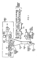
- a volumetric feeder of the type which is generally available and in use in facilities for feeding particulate material, such as coal fired electric power plants, together with a batch scale and computer control unit, to enable the volumetric feeder to feed on a weight or gravimetric basis.
- a batch scale l0 This scale is a batch feeder which weighs the material being fed and discharges it in batches.
- the batch scale may be a Model 84 Microprocessor Batch Scale which is sold by the Stock Equipment Company, Chagrin Falls, Ohio 44022-4398 U.S.A.
- the batch scale has an inlet chute l2 which may be connected to a bunker for the coal or other particulate material which is to be fed. The bunker is not shown to simplify the illustration.
- the material is discharged from the chute l2 onto a feed belt conveyor l4.
- the conveyor is driven by a motor l6 indicated as a S.MTR or scale motor.
- the discharge end of the hopper is closed by a counterweighted gate 20.
- Other gates or valves may be used to control the discharge and the terms "gate" is intended to encompass such gates, valves or other equivalent devices.
- Actuators in the form of pneumatic cylinders 22 are retracted when the gate 20 is closed and may be locked into closed position in response to a control signal, APC, to the actuators 22.
- APC control signal
- Each opening and closing of the gate 20 is sensed by a proximity sensor 24 which may be located to respond to the position of the pneumatic cylinders of the actuators 22.
- a proximity sensor 24 which may be located to respond to the position of the pneumatic cylinders of the actuators 22.
- Upon each closing a output signal PS is produced.
- the period between PS signals is a measure of the time for the discharge or dump of a batch from the weigh hopper, and therefore the rate of discharge from the batch scale.
- the apparatus uses a volumetric feeder 26.
- This feeder may be a table, drag, screw auger, pocket, or belt feeder. It is illustrated diagrammatically as a pocket feeder with a series of revolving bins which are turned by the volumetric feeder motor 28.
- This motor is a variable speed motor and responds to a speed control signal VFM.
- the material fed by the volumetric feeder 26 is discharged to a discharge chute 30 to the boiler or other process utilizing the material.
- the speed of the feeder is sensed by a tachometer 32 which is connected to the shaft of the motor 28.
- the tachometer provides output pulses VFB in a pulse train. The repetition rate of the pulses is a measure of the speed of the volumetric feeder.
- the batches of material which are discharged from the weigh hopper l8 drop into a hopper 34 and through a chute 36 into the volumetric feeder.
- the material piles up on the gate 20 and prevents the gate from pivoting in response to the weight of its counterweight 20' to the closed position.
- the material must be fed by the volumetric feeder in order to clear the hopper sufficiently to allow the gate 20 to close.
- the cycle can then start again with the gate opening to dump another load of material into the hopper 34.
- the efficiency of the volumetric feeder 26 corresponds in part to the period between openings of the gate (the rate at which the gate opens). This period is provided by the interval between the PS signals from the proximity sensor 24 and is used together with the output LC of the load cells 2l which indicate the weight of the material which is dumped, to measure the volumetric efficiency factor of the feeder 26 and control the feeder 26 so that it feeds by weight (gravimetricly).
- a computer control unit which is preferably a microprocessor controller 38, is connected by control lines (CL) such as address lines and data lines (DL) to an interface unit 40 containing digital to analog and analog to digital converters.
- CL control lines
- the interface unit provides the VFM, SM and APC signals and receives the PS and LC signals.
- the VFB signals (the tachometer pulses) are also applied to the microprocessor controller 38 and may be a direct digital input.
- the controller produces an output indicating the feed rate produced (FRP) in pounds per hour to the boiler or other process control unit
- This process control unit provides inputs for turning the entire feeder on and off (VF on/off) and a feed rate demand signal (FRD).
- FRP feed rate produced
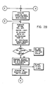
- the apparatus when the VF signal is on, the apparatus is started as indicated in the block identified with the word start in FIG. 2A. If the gate 20 is open, as indicated by the PS output the system waits until the gate closes and the APC signal is applied to the actuators 22 to latch the gate closed. The load cells are then read to obtain the tare weight. Then the scale motor is started by applying SM command signal. The load cells are continually read so long as the batch weight remains low (below a predetermined weight). When the batched weight exceeds the predetermined weight (and preferably slightly below the predetermined weight is achieved in order to allow for the inertia in the feed belt), the scale motor l6 is stopped. The load cells continued to be read.
- the tare weight is subtracted from the weight read by the load cells and the batch weight is read. Then the APC signal is turned off to release the gate 20 and the material is dumped into the hopper 34. This process repeats and the batch weights may be totalized by adding each batch weight to the total so as to provide an indication of the amount of material which is discharged from the apparatus.
- FIGS. 2A, 2B and 2C are connected by way of connectors, A to A' and B to B' and so forth, as is conventional in flow charting.
- the closings of the gate 20 is sensed, as is the tachometer 32 and the number of tachometer or tach pulses between gate closings is totalized (see FIG. 2B).
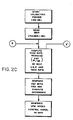
- the actual (real time) volumetric efficiency factor (VEF) is computed by dividing the stored batch weight on the preceding dump by the number of tach pulses totalized during the present gate cycle. This delay allows for the passage of the material into the volumetric feeder and takes into account the volumetric feeding efficiency of the dump or batch being fed.
- volumetric feeder is turned off (the SM signal to the scale motor being off), then the total of the tach pulses is inhibited and the volumetric efficiency factor is not computed. This takes into account the possibility that a dump may have occurred on a preceding cycle from material which was not then being fed on a real time basis into the weigh hopper l8.
- a volumetric efficiency factor number is stored in memory in the microprocessor 38. This stored factor is compared with the computed or actual volumetric efficiency factor and the difference is computed. If the difference is greater than fifty percent, this is an indication of a malfunction in the feeder and an alarm is sounded. For smaller variations between the stored and actual VEF, the stored VEF is incremented or decremented so that the actual VEF is updated and is present in memory.
- This actual VEF is used together with the tach pulses to compute the actual feed rate which is produced (FRP) as shown in FIG. 2C.
- the pulses per hour are multiplied by the volumetric efficiency factor which is in units of pounds per pulse so as to provide the feed rate output FRP in pounds per hour. This is the FRP output from the microprocessor controller 38 as shown in FIG. l.
- the feed rate demand signal FRD is compared with the computed feed rate FRP and the difference is computed. This difference is used to generate the VFM speed control signal which is proportional thereto. The speed of the volumetric feeder is then increased or decreased to so to obtain the demanded feed rate.
Landscapes
- Physics & Mathematics (AREA)
- General Physics & Mathematics (AREA)
- Filling Or Emptying Of Bunkers, Hoppers, And Tanks (AREA)
- Regulation And Control Of Combustion (AREA)
- Feeding And Controlling Fuel (AREA)
- Weight Measurement For Supplying Or Discharging Of Specified Amounts Of Material (AREA)
- Control Of Conveyors (AREA)
- Feeding Of Articles To Conveyors (AREA)
Abstract
Description
- The present invention relates to apparatus and methods for feeding particulate materials, such as coal and other bulk materials, and particularly to improved methods and apparatus for feeding material gravimetricly (on a unit weight per unit time basis) with a volumetric feeder, thereby converting the volumetric feeder into a gravimetric feeder.
- The invention is especially suitable for use in converting volumetric feeders into gravimetric feeders so as to enable coal and other particulate material to be fed by weight and eliminate variations due to density changes in the material to improve efficiency in the operation of coal fired boilers. The invention is also suitable for use in initial installations during new construction and capital equipment improvements in plants and facilities.
- Volumetric feeder conversion to gravimetric feeding has involved the replacement of the volumetric feeder with a gravimetric feeder, for example such as described in U.S. Patent 3,l87,944 issued to A.J. Stock on June 8, l965 and U.S. Patent 4,257,5l8 issued to A.J. Stock et al on March 24, l98l. It has been discovered, in accordance with this invention that a volumetric feeder may be converted to feed gravimetricly by the delivery thereto of the material in weighed batches, particularly from a batch scale, where the period of the delivery of the batches and the speed of the volumetric feeder are sensed together with the weight of the batches and used to derive outputs representing the feed rate on a gravimetric basis (unit weight per unit time). The volumetric feeder speed can be controlled so as to produce a feed rate in accordance with a demand signal, for example from the boiler or other process which utilizes the material discharged from the feeder.
- While feed rate control of devices which feed by volume have been proposed (see, U.S. Patent 2,7l4,472 issued August 2, l955 and U.S. Patent 3,00l,672 issued September 26, l96l), precise gravimetric feeding over a wide range of feed rates has not been accomplished. The invention overcomes the problem of providing wide feed rate range and accuracy of control, by continuously monitoring the volumetric efficiency of the volumetric feeder and correcting of the variation in the volumetric efficiency of the volumetric feeder. The volumetric efficiency factor is the ratio of the weight of the material to the speed of the feeder. In accordance with this invention, the volumetric efficiency factor is computed for each batch of material feed into the volumetric feeder from the batch scale feeder, and used to correct a stored volumetric efficiency factor. The correct volumetric efficiency is used to compute the feed rate and to control the volumetric feeder speed so that the feed rate can be changed to correspond to a demanded feed rate from the process (the boiler) which is using the material discharged from the volumetric feeder.
- Accordingly, it is the principal object of the present invention to provide improved methods and apparatus for converting a volumetric feeder into a gravimetric feeder.
- It is another object of the present invention to provide improved feeder apparatus which may utilize a volumetric feeder of the type which is generally available and in use in facilities for feeding particulate material, such as coal fired electric power plants, together with a batch scale and computer control unit, to enable the volumetric feeder to feed on a weight or gravimetric basis.
- It is a still further object of the present invention to provide improved apparatus for feeding particulate material gravimetrically, which incorporates a volumetric feeder and may be used instead of a complete replacement of the volumetric feeder with a gravimetric feeder, when it is desired to feed the material by weight, instead of by volume.
- The foregoing and other objects, features and advantages of the invention as well as a presently preferred embodiment thereof will become more apparent from a reading of the following description in connection with the accompanying drawings in which:
- FIG. l is a schematic diagram illustrating apparatus for feeding particulate material in accordance with a presently preferred embodiment of the invention;
and - FIGS. 2A, 2B and 2C, taken together, constitute a flowchart illustrating the programming of the computer control unit (microprocessor controller) and the operation of the apparatus illustrated in FIG. l.
- Referring more particularly to FIG. l of the drawings there is shown a batch scale l0. This scale is a batch feeder which weighs the material being fed and discharges it in batches. The batch scale may be a Model 84 Microprocessor Batch Scale which is sold by the Stock Equipment Company, Chagrin Falls, Ohio 44022-4398 U.S.A. The batch scale has an inlet chute l2 which may be connected to a bunker for the coal or other particulate material which is to be fed. The bunker is not shown to simplify the illustration. The material is discharged from the chute l2 onto a feed belt conveyor l4. The conveyor is driven by a motor l6 indicated as a S.MTR or scale motor. The feed belt when the motor is on as determined by a control signal SM, drops the material into a weigh hopper l8 which may be mounted on load cells 2. The discharge end of the hopper is closed by a
counterweighted gate 20. Other gates or valves may be used to control the discharge and the terms "gate" is intended to encompass such gates, valves or other equivalent devices. - Actuators, in the form of
pneumatic cylinders 22 are retracted when thegate 20 is closed and may be locked into closed position in response to a control signal, APC, to theactuators 22. When the signal APC is removed the gate is released and allows the discharge of the material from the weigh hopper l8. Each opening and closing of thegate 20 is sensed by aproximity sensor 24 which may be located to respond to the position of the pneumatic cylinders of theactuators 22. Upon each closing a output signal PS is produced. The period between PS signals is a measure of the time for the discharge or dump of a batch from the weigh hopper, and therefore the rate of discharge from the batch scale. - The apparatus uses a
volumetric feeder 26. This feeder may be a table, drag, screw auger, pocket, or belt feeder. It is illustrated diagrammatically as a pocket feeder with a series of revolving bins which are turned by thevolumetric feeder motor 28. This motor is a variable speed motor and responds to a speed control signal VFM. The material fed by thevolumetric feeder 26 is discharged to adischarge chute 30 to the boiler or other process utilizing the material. The speed of the feeder is sensed by atachometer 32 which is connected to the shaft of themotor 28. The tachometer provides output pulses VFB in a pulse train. The repetition rate of the pulses is a measure of the speed of the volumetric feeder. - The batches of material which are discharged from the weigh hopper l8 drop into a
hopper 34 and through achute 36 into the volumetric feeder. As the chute and hopper fill, the material piles up on thegate 20 and prevents the gate from pivoting in response to the weight of its counterweight 20' to the closed position. The material must be fed by the volumetric feeder in order to clear the hopper sufficiently to allow thegate 20 to close. The cycle can then start again with the gate opening to dump another load of material into thehopper 34. - It will be seen, therefore, that the efficiency of the
volumetric feeder 26 corresponds in part to the period between openings of the gate (the rate at which the gate opens). This period is provided by the interval between the PS signals from theproximity sensor 24 and is used together with the output LC of the load cells 2l which indicate the weight of the material which is dumped, to measure the volumetric efficiency factor of thefeeder 26 and control thefeeder 26 so that it feeds by weight (gravimetricly). - A computer control unit, which is preferably a
microprocessor controller 38, is connected by control lines (CL) such as address lines and data lines (DL) to aninterface unit 40 containing digital to analog and analog to digital converters. The interface unit provides the VFM, SM and APC signals and receives the PS and LC signals. The VFB signals (the tachometer pulses) are also applied to themicroprocessor controller 38 and may be a direct digital input. The controller produces an output indicating the feed rate produced (FRP) in pounds per hour to the boiler or other process control unit This process control unit provides inputs for turning the entire feeder on and off (VF on/off) and a feed rate demand signal (FRD). - Referring to FIGS. 2A, 2B and 2C, when the VF signal is on, the apparatus is started as indicated in the block identified with the word start in FIG. 2A. If the
gate 20 is open, as indicated by the PS output the system waits until the gate closes and the APC signal is applied to theactuators 22 to latch the gate closed. The load cells are then read to obtain the tare weight. Then the scale motor is started by applying SM command signal. The load cells are continually read so long as the batch weight remains low (below a predetermined weight). When the batched weight exceeds the predetermined weight (and preferably slightly below the predetermined weight is achieved in order to allow for the inertia in the feed belt), the scale motor l6 is stopped. The load cells continued to be read. The tare weight is subtracted from the weight read by the load cells and the batch weight is read. Then the APC signal is turned off to release thegate 20 and the material is dumped into thehopper 34. This process repeats and the batch weights may be totalized by adding each batch weight to the total so as to provide an indication of the amount of material which is discharged from the apparatus. - The flow chart diagrams of FIGS. 2A, 2B and 2C are connected by way of connectors, A to A' and B to B' and so forth, as is conventional in flow charting.
- The closings of the
gate 20 is sensed, as is thetachometer 32 and the number of tachometer or tach pulses between gate closings is totalized (see FIG. 2B). The actual (real time) volumetric efficiency factor (VEF) is computed by dividing the stored batch weight on the preceding dump by the number of tach pulses totalized during the present gate cycle. This delay allows for the passage of the material into the volumetric feeder and takes into account the volumetric feeding efficiency of the dump or batch being fed. - If the volumetric feeder is turned off (the SM signal to the scale motor being off), then the total of the tach pulses is inhibited and the volumetric efficiency factor is not computed. This takes into account the possibility that a dump may have occurred on a preceding cycle from material which was not then being fed on a real time basis into the weigh hopper l8. A volumetric efficiency factor number is stored in memory in the
microprocessor 38. This stored factor is compared with the computed or actual volumetric efficiency factor and the difference is computed. If the difference is greater than fifty percent, this is an indication of a malfunction in the feeder and an alarm is sounded. For smaller variations between the stored and actual VEF, the stored VEF is incremented or decremented so that the actual VEF is updated and is present in memory. - This actual VEF is used together with the tach pulses to compute the actual feed rate which is produced (FRP) as shown in FIG. 2C. The pulses per hour are multiplied by the volumetric efficiency factor which is in units of pounds per pulse so as to provide the feed rate output FRP in pounds per hour. This is the FRP output from the
microprocessor controller 38 as shown in FIG. l. - In the event that it is desired to control the system to provide the demanded feed rate, the feed rate demand signal FRD is compared with the computed feed rate FRP and the difference is computed. This difference is used to generate the VFM speed control signal which is proportional thereto. The speed of the volumetric feeder is then increased or decreased to so to obtain the demanded feed rate.
- From the foregoing description it will be apparent that there has been provided improved methods and apparatus for feeding of particulate material, and particularly an improved method and apparatus for converting a volumetric feeder into a gravimetric feeder. While and exemplary embodiment of the invention has been described, variations and modifications therein, within the scope of the invention, will undoubtedly become apparent to those skilled in the art. Accordingly the foregoing description should be taken as illustrative and not in a limiting sense.
Claims (10)
Applications Claiming Priority (2)
| Application Number | Priority Date | Filing Date | Title |
|---|---|---|---|
| US769055 | 1985-08-26 | ||
| US06/769,055 US4793512A (en) | 1985-08-26 | 1985-08-26 | Apparatus and method for feeding particulate material such as coal and other bulk materials |
Publications (3)
| Publication Number | Publication Date |
|---|---|
| EP0213524A2 true EP0213524A2 (en) | 1987-03-11 |
| EP0213524A3 EP0213524A3 (en) | 1988-06-15 |
| EP0213524B1 EP0213524B1 (en) | 1989-10-11 |
Family
ID=25084303
Family Applications (1)
| Application Number | Title | Priority Date | Filing Date |
|---|---|---|---|
| EP86111370A Expired EP0213524B1 (en) | 1985-08-26 | 1986-08-18 | Apparatus and method for feeding particulate material such as coal and other bulk materials |
Country Status (7)
| Country | Link |
|---|---|
| US (1) | US4793512A (en) |
| EP (1) | EP0213524B1 (en) |
| JP (1) | JPS6250624A (en) |
| CN (1) | CN1025315C (en) |
| CA (1) | CA1275863C (en) |
| DE (1) | DE3666293D1 (en) |
| IN (1) | IN167034B (en) |
Cited By (3)
| Publication number | Priority date | Publication date | Assignee | Title |
|---|---|---|---|---|
| GB2239966A (en) * | 1989-11-21 | 1991-07-17 | Gen Signal Corp | Controlling discharge rates of loss-in-weight feeders |
| US7340967B2 (en) | 2005-01-31 | 2008-03-11 | Maillefer Sa | Device for measuring a mass flow rate of a particulate material |
| CN108622643A (en) * | 2017-03-24 | 2018-10-09 | 天津市晟富达纺织品有限公司 | A kind of carpet manufacture automatical feeding system |
Families Citing this family (16)
| Publication number | Priority date | Publication date | Assignee | Title |
|---|---|---|---|---|
| EP0495032A1 (en) * | 1990-08-07 | 1992-07-22 | HOEBERIGS, Jean Marie Mathieu | Automatic portioning and weighing arrangement |
| US5450984A (en) * | 1994-04-29 | 1995-09-19 | K-Tron Technologies, Inc. | Material feeding apparatus |
| US5992689A (en) * | 1996-11-04 | 1999-11-30 | Jr Johanson, Inc. | Variable flow rate hopper to reduce feed pulsation to a downstream process |
| US5784974A (en) * | 1997-04-22 | 1998-07-28 | General Signal Corporation | System for improving fuel feed control of volumetric coal feeders |
| US5967375A (en) * | 1997-08-07 | 1999-10-19 | Crafco, Inc. | Sealant melter with retrofittable sealant block feed assembly |
| US6211470B1 (en) | 1999-11-22 | 2001-04-03 | Westvaco Corporation | Height measurement apparatus for determining the volume/density of wood chips on a conveyor |
| US6811301B2 (en) | 2002-03-29 | 2004-11-02 | Hydreclaim, Inc. | Feeder control system for an automated blender system |
| US10018986B2 (en) * | 2014-06-05 | 2018-07-10 | Clarence Richard | Mass flow control for a conveyor system |
| CN104089689B (en) * | 2014-07-15 | 2017-06-13 | 湖南三一路面机械有限公司 | A kind of material measuring device and method and engineering machinery |
| EP3040694A1 (en) * | 2015-01-05 | 2016-07-06 | Plast-Control GmbH | Granulate metering assembly for plastic processing machines |
| US9809386B2 (en) * | 2015-06-02 | 2017-11-07 | Nordic Minesteel Technologies Inc. | Counterweight ore chute system |
| CN105716698B (en) * | 2016-03-30 | 2019-02-26 | 汕头市悦熙机械设备有限公司 | A kind of material weighing device and weighing method, cold press |
| CN105758503A (en) * | 2016-04-07 | 2016-07-13 | 远光共创智能科技股份有限公司 | Coal handling system firing coal sub-warehouse metering system and metering method thereof |
| CN106379724B (en) * | 2016-11-14 | 2018-08-07 | 鞍钢集团工程技术有限公司 | A kind of adhesive tape chain-drive section transhipment baffle suppression dust control device |
| CN114056852A (en) * | 2017-05-12 | 2022-02-18 | 刘素华 | Multidimensional integral leakage-resistant belt with side strip positioning function |
| CN114739494B (en) * | 2022-05-19 | 2024-02-06 | 柳州钢铁股份有限公司 | Method for calibrating belt scale precision on line |
Citations (3)
| Publication number | Priority date | Publication date | Assignee | Title |
|---|---|---|---|---|
| DE2152533A1 (en) * | 1970-10-23 | 1972-04-27 | List Heinz | Process for the continuous metering of several components of a mixed product and a device for carrying out this process |
| EP0103475A2 (en) * | 1982-09-11 | 1984-03-21 | Kabushiki Kaisha Ishida Koki Seisakusho | Weighing and packaging methods and apparatus therefor |
| EP0104062A2 (en) * | 1982-09-16 | 1984-03-28 | Kabushiki Kaisha Ishida Koki Seisakusho | Automatic weighing and packing methods and apparatus therefor |
Family Cites Families (15)
| Publication number | Priority date | Publication date | Assignee | Title |
|---|---|---|---|---|
| US2714472A (en) * | 1950-11-17 | 1955-08-02 | Richardson Scale Company | Weighing apparatus |
| US3001672A (en) * | 1958-07-01 | 1961-09-26 | Eugene A Wahl | Method and apparatus for powder feeding |
| US2983325A (en) * | 1960-02-04 | 1961-05-09 | James Hunter Inc | Fiber feeding apparatus |
| US3187944A (en) * | 1962-10-09 | 1965-06-08 | Arthur J Stock | Gravimetric feeder and method of filling voids therein or in other pressure vessels |
| US3967758A (en) * | 1975-02-18 | 1976-07-06 | Acrison, Inc. | Automatically controlled weigh feeding apparatus |
| JPS5245594Y2 (en) * | 1973-06-02 | 1977-10-17 | ||
| JPS5181155A (en) * | 1975-01-13 | 1976-07-15 | Shimadzu Corp | |
| JPS6045362B2 (en) * | 1977-04-12 | 1985-10-09 | 株式会社クボタ | Fixed amount dispensing device |
| JPS53139585A (en) * | 1977-05-11 | 1978-12-05 | Ai Ii Shii Kk | Device for counting blood corpuscle cell |
| JPS5433761A (en) * | 1977-08-20 | 1979-03-12 | Kubota Ltd | Method of measuring yield rate in processor |
| US4257518A (en) * | 1978-10-25 | 1981-03-24 | Stock Equipment Company | Feeder for particulate material |
| US4272824A (en) * | 1979-08-17 | 1981-06-09 | Pennant Products, Inc. | Batch product preparation |
| JPS56148019A (en) * | 1980-04-18 | 1981-11-17 | Kubota Ltd | Flow rate controlling method using measuring hopper |
| JPS5724214A (en) * | 1980-07-21 | 1982-02-08 | Mitsubishi Heavy Ind Ltd | Molding method apparatus of cylindrical material by tube spinning |
| DE3146667C2 (en) * | 1981-11-25 | 1984-12-06 | Werner & Pfleiderer, 7000 Stuttgart | Method and device for mixing and metering several mix components |
-
1985
- 1985-08-26 US US06/769,055 patent/US4793512A/en not_active Expired - Lifetime
-
1986
- 1986-07-18 CA CA000514127A patent/CA1275863C/en not_active Expired - Lifetime
- 1986-07-21 IN IN652/DEL/86A patent/IN167034B/en unknown
- 1986-08-18 EP EP86111370A patent/EP0213524B1/en not_active Expired
- 1986-08-18 DE DE8686111370T patent/DE3666293D1/en not_active Expired
- 1986-08-21 CN CN86105103.3A patent/CN1025315C/en not_active Expired - Lifetime
- 1986-08-26 JP JP61199875A patent/JPS6250624A/en active Granted
Patent Citations (3)
| Publication number | Priority date | Publication date | Assignee | Title |
|---|---|---|---|---|
| DE2152533A1 (en) * | 1970-10-23 | 1972-04-27 | List Heinz | Process for the continuous metering of several components of a mixed product and a device for carrying out this process |
| EP0103475A2 (en) * | 1982-09-11 | 1984-03-21 | Kabushiki Kaisha Ishida Koki Seisakusho | Weighing and packaging methods and apparatus therefor |
| EP0104062A2 (en) * | 1982-09-16 | 1984-03-28 | Kabushiki Kaisha Ishida Koki Seisakusho | Automatic weighing and packing methods and apparatus therefor |
Non-Patent Citations (1)
| Title |
|---|
| INSTRUMENTS & CONTROL SYSTEMS, vol. 51, no. 8, August 1978, pages 29-35; J. HALL: "What's going on in weighing" * |
Cited By (4)
| Publication number | Priority date | Publication date | Assignee | Title |
|---|---|---|---|---|
| GB2239966A (en) * | 1989-11-21 | 1991-07-17 | Gen Signal Corp | Controlling discharge rates of loss-in-weight feeders |
| GB2239966B (en) * | 1989-11-21 | 1994-01-12 | Gen Signal Corp | System for precisely controlling discharge rates of loss-in-weight feeder systems |
| US7340967B2 (en) | 2005-01-31 | 2008-03-11 | Maillefer Sa | Device for measuring a mass flow rate of a particulate material |
| CN108622643A (en) * | 2017-03-24 | 2018-10-09 | 天津市晟富达纺织品有限公司 | A kind of carpet manufacture automatical feeding system |
Also Published As
| Publication number | Publication date |
|---|---|
| JPH0554048B2 (en) | 1993-08-11 |
| DE3666293D1 (en) | 1989-11-16 |
| JPS6250624A (en) | 1987-03-05 |
| CN1025315C (en) | 1994-07-06 |
| EP0213524A3 (en) | 1988-06-15 |
| CN86105103A (en) | 1987-04-08 |
| IN167034B (en) | 1990-08-18 |
| EP0213524B1 (en) | 1989-10-11 |
| US4793512A (en) | 1988-12-27 |
| CA1275863C (en) | 1990-11-06 |
Similar Documents
| Publication | Publication Date | Title |
|---|---|---|
| EP0213524B1 (en) | Apparatus and method for feeding particulate material such as coal and other bulk materials | |
| US4222448A (en) | Automatic batch weighing system | |
| CA1099689A (en) | Weigh feeding apparatus | |
| US4320855A (en) | Weigh feeding apparatus | |
| USRE32101E (en) | Weigh feeding apparatus | |
| US4210963A (en) | Weigh feeder system | |
| CA1315263C (en) | Wild flow loss-in-weight weighing system | |
| CA1216867A (en) | Loss-in-weight gravimetric feeder | |
| EP0060701B1 (en) | Method and apparatus for controlling zero adjustment of weight sensor | |
| USRE32102E (en) | Weigh feeding apparatus | |
| JPH04503867A (en) | Apparatus, method and use of this method for detecting product flow | |
| EP0097532A2 (en) | Combinatorial weighing apparatus | |
| HU193249B (en) | Method and apparatus for measuring the transit power of continuously flown bulk materials | |
| EP0104062B1 (en) | Automatic weighing and packing methods and apparatus therefor | |
| EP0064554A1 (en) | Combination weighing method and apparatus | |
| JPH02657Y2 (en) | ||
| EP0796423B1 (en) | Process and device for the continual gravimetric metered dispensing and mass flow rate determination of free-flowing materials | |
| EP0103476A2 (en) | Combinatorial weighing method and apparatus therefor | |
| US4164260A (en) | Method and apparatus for controlling the average weights of commodities in package form | |
| CA1094039A (en) | Weigh feeder system | |
| JP3573831B2 (en) | Metering device | |
| JPH0254886B2 (en) | ||
| GB2141245A (en) | Batch weighing apparatus | |
| JP2699100B2 (en) | Quantitative filling method | |
| CN2537002Y (en) | Nucleon balancer online metering device |
Legal Events
| Date | Code | Title | Description |
|---|---|---|---|
| PUAI | Public reference made under article 153(3) epc to a published international application that has entered the european phase |
Free format text: ORIGINAL CODE: 0009012 |
|
| AK | Designated contracting states |
Kind code of ref document: A2 Designated state(s): DE FR GB IT |
|
| PUAL | Search report despatched |
Free format text: ORIGINAL CODE: 0009013 |
|
| AK | Designated contracting states |
Kind code of ref document: A3 Designated state(s): DE FR GB IT |
|
| 17P | Request for examination filed |
Effective date: 19881013 |
|
| 17Q | First examination report despatched |
Effective date: 19881222 |
|
| ITF | It: translation for a ep patent filed |
Owner name: BARZANO' E ZANARDO ROMA S.P.A. |
|
| GRAA | (expected) grant |
Free format text: ORIGINAL CODE: 0009210 |
|
| AK | Designated contracting states |
Kind code of ref document: B1 Designated state(s): DE FR GB IT |
|
| REF | Corresponds to: |
Ref document number: 3666293 Country of ref document: DE Date of ref document: 19891116 |
|
| ET | Fr: translation filed | ||
| PLBE | No opposition filed within time limit |
Free format text: ORIGINAL CODE: 0009261 |
|
| STAA | Information on the status of an ep patent application or granted ep patent |
Free format text: STATUS: NO OPPOSITION FILED WITHIN TIME LIMIT |
|
| 26N | No opposition filed | ||
| ITTA | It: last paid annual fee | ||
| PGFP | Annual fee paid to national office [announced via postgrant information from national office to epo] |
Ref country code: FR Payment date: 20000709 Year of fee payment: 15 |
|
| PGFP | Annual fee paid to national office [announced via postgrant information from national office to epo] |
Ref country code: DE Payment date: 20000727 Year of fee payment: 15 |
|
| REG | Reference to a national code |
Ref country code: GB Ref legal event code: IF02 |
|
| PG25 | Lapsed in a contracting state [announced via postgrant information from national office to epo] |
Ref country code: FR Free format text: LAPSE BECAUSE OF NON-PAYMENT OF DUE FEES Effective date: 20020430 |
|
| PG25 | Lapsed in a contracting state [announced via postgrant information from national office to epo] |
Ref country code: DE Free format text: LAPSE BECAUSE OF NON-PAYMENT OF DUE FEES Effective date: 20020501 |
|
| REG | Reference to a national code |
Ref country code: FR Ref legal event code: ST |
|
| PGFP | Annual fee paid to national office [announced via postgrant information from national office to epo] |
Ref country code: GB Payment date: 20040121 Year of fee payment: 18 |
|
| PG25 | Lapsed in a contracting state [announced via postgrant information from national office to epo] |
Ref country code: GB Free format text: LAPSE BECAUSE OF NON-PAYMENT OF DUE FEES Effective date: 20040818 |
|
| GBPC | Gb: european patent ceased through non-payment of renewal fee |
Effective date: 20040818 |
|
| PG25 | Lapsed in a contracting state [announced via postgrant information from national office to epo] |
Ref country code: IT Free format text: LAPSE BECAUSE OF NON-PAYMENT OF DUE FEES;WARNING: LAPSES OF ITALIAN PATENTS WITH EFFECTIVE DATE BEFORE 2007 MAY HAVE OCCURRED AT ANY TIME BEFORE 2007. THE CORRECT EFFECTIVE DATE MAY BE DIFFERENT FROM THE ONE RECORDED. Effective date: 20050818 |