EP0212915A2 - Fiber laser sensor - Google Patents
Fiber laser sensor Download PDFInfo
- Publication number
- EP0212915A2 EP0212915A2 EP19860306088 EP86306088A EP0212915A2 EP 0212915 A2 EP0212915 A2 EP 0212915A2 EP 19860306088 EP19860306088 EP 19860306088 EP 86306088 A EP86306088 A EP 86306088A EP 0212915 A2 EP0212915 A2 EP 0212915A2
- Authority
- EP
- European Patent Office
- Prior art keywords
- fiber
- oscillators
- oscillator
- energy
- fiber laser
- Prior art date
- Legal status (The legal status is an assumption and is not a legal conclusion. Google has not performed a legal analysis and makes no representation as to the accuracy of the status listed.)
- Granted
Links
- 239000000835 fiber Substances 0.000 title claims abstract description 139
- 230000003287 optical effect Effects 0.000 claims abstract description 36
- 230000010287 polarization Effects 0.000 claims abstract description 27
- 230000010355 oscillation Effects 0.000 claims abstract description 21
- 230000008878 coupling Effects 0.000 claims abstract description 17
- 238000010168 coupling process Methods 0.000 claims abstract description 17
- 238000005859 coupling reaction Methods 0.000 claims abstract description 17
- 238000005253 cladding Methods 0.000 claims description 19
- 238000012546 transfer Methods 0.000 claims description 13
- 238000005086 pumping Methods 0.000 claims description 11
- 239000002131 composite material Substances 0.000 claims description 7
- 239000013307 optical fiber Substances 0.000 claims description 6
- 238000003825 pressing Methods 0.000 claims 1
- 239000012780 transparent material Substances 0.000 claims 1
- 238000000034 method Methods 0.000 abstract description 18
- 239000011162 core material Substances 0.000 description 111
- 238000010276 construction Methods 0.000 description 16
- 239000000463 material Substances 0.000 description 15
- 230000008859 change Effects 0.000 description 12
- 238000010586 diagram Methods 0.000 description 11
- 238000002310 reflectometry Methods 0.000 description 9
- 230000000694 effects Effects 0.000 description 8
- 239000011521 glass Substances 0.000 description 8
- 230000035559 beat frequency Effects 0.000 description 6
- 230000006835 compression Effects 0.000 description 6
- 238000007906 compression Methods 0.000 description 6
- 238000012545 processing Methods 0.000 description 5
- 238000007796 conventional method Methods 0.000 description 4
- 230000007613 environmental effect Effects 0.000 description 4
- 238000005259 measurement Methods 0.000 description 4
- 229910052779 Neodymium Inorganic materials 0.000 description 3
- 238000004519 manufacturing process Methods 0.000 description 3
- 239000000203 mixture Substances 0.000 description 3
- QEFYFXOXNSNQGX-UHFFFAOYSA-N neodymium atom Chemical compound [Nd] QEFYFXOXNSNQGX-UHFFFAOYSA-N 0.000 description 3
- 230000003071 parasitic effect Effects 0.000 description 3
- 230000035945 sensitivity Effects 0.000 description 3
- 238000010009 beating Methods 0.000 description 2
- 238000006243 chemical reaction Methods 0.000 description 2
- 239000011248 coating agent Substances 0.000 description 2
- 238000000576 coating method Methods 0.000 description 2
- 239000002178 crystalline material Substances 0.000 description 2
- 238000001514 detection method Methods 0.000 description 2
- 230000009977 dual effect Effects 0.000 description 2
- 230000008569 process Effects 0.000 description 2
- 230000004044 response Effects 0.000 description 2
- 239000004065 semiconductor Substances 0.000 description 2
- 229910052691 Erbium Inorganic materials 0.000 description 1
- 229910052689 Holmium Inorganic materials 0.000 description 1
- VYPSYNLAJGMNEJ-UHFFFAOYSA-N Silicium dioxide Chemical compound O=[Si]=O VYPSYNLAJGMNEJ-UHFFFAOYSA-N 0.000 description 1
- 238000010521 absorption reaction Methods 0.000 description 1
- 230000009471 action Effects 0.000 description 1
- 239000011149 active material Substances 0.000 description 1
- 238000004891 communication Methods 0.000 description 1
- 150000001875 compounds Chemical class 0.000 description 1
- 230000003247 decreasing effect Effects 0.000 description 1
- 230000001419 dependent effect Effects 0.000 description 1
- 239000002019 doping agent Substances 0.000 description 1
- 230000005684 electric field Effects 0.000 description 1
- 238000005516 engineering process Methods 0.000 description 1
- UYAHIZSMUZPPFV-UHFFFAOYSA-N erbium Chemical compound [Er] UYAHIZSMUZPPFV-UHFFFAOYSA-N 0.000 description 1
- 230000005284 excitation Effects 0.000 description 1
- 239000005350 fused silica glass Substances 0.000 description 1
- KJZYNXUDTRRSPN-UHFFFAOYSA-N holmium atom Chemical compound [Ho] KJZYNXUDTRRSPN-UHFFFAOYSA-N 0.000 description 1
- 238000002347 injection Methods 0.000 description 1
- 239000007924 injection Substances 0.000 description 1
- 239000011159 matrix material Substances 0.000 description 1
- 238000012544 monitoring process Methods 0.000 description 1
- 238000004886 process control Methods 0.000 description 1
- 238000009877 rendering Methods 0.000 description 1
- 238000000926 separation method Methods 0.000 description 1
- 230000003595 spectral effect Effects 0.000 description 1
- 230000002277 temperature effect Effects 0.000 description 1
Images

Classifications
-
- H—ELECTRICITY
- H01—ELECTRIC ELEMENTS
- H01S—DEVICES USING THE PROCESS OF LIGHT AMPLIFICATION BY STIMULATED EMISSION OF RADIATION [LASER] TO AMPLIFY OR GENERATE LIGHT; DEVICES USING STIMULATED EMISSION OF ELECTROMAGNETIC RADIATION IN WAVE RANGES OTHER THAN OPTICAL
- H01S3/00—Lasers, i.e. devices using stimulated emission of electromagnetic radiation in the infrared, visible or ultraviolet wave range
- H01S3/23—Arrangements of two or more lasers not provided for in groups H01S3/02 - H01S3/22, e.g. tandem arrangements of separate active media
- H01S3/2383—Parallel arrangements
-
- G—PHYSICS
- G01—MEASURING; TESTING
- G01D—MEASURING NOT SPECIALLY ADAPTED FOR A SPECIFIC VARIABLE; ARRANGEMENTS FOR MEASURING TWO OR MORE VARIABLES NOT COVERED IN A SINGLE OTHER SUBCLASS; TARIFF METERING APPARATUS; MEASURING OR TESTING NOT OTHERWISE PROVIDED FOR
- G01D5/00—Mechanical means for transferring the output of a sensing member; Means for converting the output of a sensing member to another variable where the form or nature of the sensing member does not constrain the means for converting; Transducers not specially adapted for a specific variable
- G01D5/26—Mechanical means for transferring the output of a sensing member; Means for converting the output of a sensing member to another variable where the form or nature of the sensing member does not constrain the means for converting; Transducers not specially adapted for a specific variable characterised by optical transfer means, i.e. using infrared, visible, or ultraviolet light
- G01D5/32—Mechanical means for transferring the output of a sensing member; Means for converting the output of a sensing member to another variable where the form or nature of the sensing member does not constrain the means for converting; Transducers not specially adapted for a specific variable characterised by optical transfer means, i.e. using infrared, visible, or ultraviolet light with attenuation or whole or partial obturation of beams of light
- G01D5/34—Mechanical means for transferring the output of a sensing member; Means for converting the output of a sensing member to another variable where the form or nature of the sensing member does not constrain the means for converting; Transducers not specially adapted for a specific variable characterised by optical transfer means, i.e. using infrared, visible, or ultraviolet light with attenuation or whole or partial obturation of beams of light the beams of light being detected by photocells
- G01D5/353—Mechanical means for transferring the output of a sensing member; Means for converting the output of a sensing member to another variable where the form or nature of the sensing member does not constrain the means for converting; Transducers not specially adapted for a specific variable characterised by optical transfer means, i.e. using infrared, visible, or ultraviolet light with attenuation or whole or partial obturation of beams of light the beams of light being detected by photocells influencing the transmission properties of an optical fibre
- G01D5/35338—Mechanical means for transferring the output of a sensing member; Means for converting the output of a sensing member to another variable where the form or nature of the sensing member does not constrain the means for converting; Transducers not specially adapted for a specific variable characterised by optical transfer means, i.e. using infrared, visible, or ultraviolet light with attenuation or whole or partial obturation of beams of light the beams of light being detected by photocells influencing the transmission properties of an optical fibre using other arrangements than interferometer arrangements
- G01D5/35341—Sensor working in transmission
- G01D5/35345—Sensor working in transmission using Amplitude variations to detect the measured quantity
-
- G—PHYSICS
- G02—OPTICS
- G02B—OPTICAL ELEMENTS, SYSTEMS OR APPARATUS
- G02B6/00—Light guides; Structural details of arrangements comprising light guides and other optical elements, e.g. couplings
- G02B6/24—Coupling light guides
- G02B6/26—Optical coupling means
- G02B6/28—Optical coupling means having data bus means, i.e. plural waveguides interconnected and providing an inherently bidirectional system by mixing and splitting signals
- G02B6/2804—Optical coupling means having data bus means, i.e. plural waveguides interconnected and providing an inherently bidirectional system by mixing and splitting signals forming multipart couplers without wavelength selective elements, e.g. "T" couplers, star couplers
- G02B6/2821—Optical coupling means having data bus means, i.e. plural waveguides interconnected and providing an inherently bidirectional system by mixing and splitting signals forming multipart couplers without wavelength selective elements, e.g. "T" couplers, star couplers using lateral coupling between contiguous fibres to split or combine optical signals
- G02B6/2826—Optical coupling means having data bus means, i.e. plural waveguides interconnected and providing an inherently bidirectional system by mixing and splitting signals forming multipart couplers without wavelength selective elements, e.g. "T" couplers, star couplers using lateral coupling between contiguous fibres to split or combine optical signals using mechanical machining means for shaping of the couplers, e.g. grinding or polishing
-
- G—PHYSICS
- G02—OPTICS
- G02B—OPTICAL ELEMENTS, SYSTEMS OR APPARATUS
- G02B6/00—Light guides; Structural details of arrangements comprising light guides and other optical elements, e.g. couplings
- G02B6/24—Coupling light guides
- G02B6/26—Optical coupling means
- G02B6/28—Optical coupling means having data bus means, i.e. plural waveguides interconnected and providing an inherently bidirectional system by mixing and splitting signals
- G02B6/2804—Optical coupling means having data bus means, i.e. plural waveguides interconnected and providing an inherently bidirectional system by mixing and splitting signals forming multipart couplers without wavelength selective elements, e.g. "T" couplers, star couplers
- G02B6/2821—Optical coupling means having data bus means, i.e. plural waveguides interconnected and providing an inherently bidirectional system by mixing and splitting signals forming multipart couplers without wavelength selective elements, e.g. "T" couplers, star couplers using lateral coupling between contiguous fibres to split or combine optical signals
- G02B6/2843—Optical coupling means having data bus means, i.e. plural waveguides interconnected and providing an inherently bidirectional system by mixing and splitting signals forming multipart couplers without wavelength selective elements, e.g. "T" couplers, star couplers using lateral coupling between contiguous fibres to split or combine optical signals the couplers having polarisation maintaining or holding properties
-
- G—PHYSICS
- G02—OPTICS
- G02F—OPTICAL DEVICES OR ARRANGEMENTS FOR THE CONTROL OF LIGHT BY MODIFICATION OF THE OPTICAL PROPERTIES OF THE MEDIA OF THE ELEMENTS INVOLVED THEREIN; NON-LINEAR OPTICS; FREQUENCY-CHANGING OF LIGHT; OPTICAL LOGIC ELEMENTS; OPTICAL ANALOGUE/DIGITAL CONVERTERS
- G02F1/00—Devices or arrangements for the control of the intensity, colour, phase, polarisation or direction of light arriving from an independent light source, e.g. switching, gating or modulating; Non-linear optics
- G02F1/01—Devices or arrangements for the control of the intensity, colour, phase, polarisation or direction of light arriving from an independent light source, e.g. switching, gating or modulating; Non-linear optics for the control of the intensity, phase, polarisation or colour
- G02F1/0128—Devices or arrangements for the control of the intensity, colour, phase, polarisation or direction of light arriving from an independent light source, e.g. switching, gating or modulating; Non-linear optics for the control of the intensity, phase, polarisation or colour based on electro-mechanical, magneto-mechanical, elasto-optic effects
- G02F1/0131—Devices or arrangements for the control of the intensity, colour, phase, polarisation or direction of light arriving from an independent light source, e.g. switching, gating or modulating; Non-linear optics for the control of the intensity, phase, polarisation or colour based on electro-mechanical, magneto-mechanical, elasto-optic effects based on photo-elastic effects, e.g. mechanically induced birefringence
- G02F1/0134—Devices or arrangements for the control of the intensity, colour, phase, polarisation or direction of light arriving from an independent light source, e.g. switching, gating or modulating; Non-linear optics for the control of the intensity, phase, polarisation or colour based on electro-mechanical, magneto-mechanical, elasto-optic effects based on photo-elastic effects, e.g. mechanically induced birefringence in optical waveguides
-
- H—ELECTRICITY
- H01—ELECTRIC ELEMENTS
- H01S—DEVICES USING THE PROCESS OF LIGHT AMPLIFICATION BY STIMULATED EMISSION OF RADIATION [LASER] TO AMPLIFY OR GENERATE LIGHT; DEVICES USING STIMULATED EMISSION OF ELECTROMAGNETIC RADIATION IN WAVE RANGES OTHER THAN OPTICAL
- H01S3/00—Lasers, i.e. devices using stimulated emission of electromagnetic radiation in the infrared, visible or ultraviolet wave range
- H01S3/05—Construction or shape of optical resonators; Accommodation of active medium therein; Shape of active medium
- H01S3/06—Construction or shape of active medium
- H01S3/063—Waveguide lasers, i.e. whereby the dimensions of the waveguide are of the order of the light wavelength
- H01S3/067—Fibre lasers
-
- G—PHYSICS
- G02—OPTICS
- G02B—OPTICAL ELEMENTS, SYSTEMS OR APPARATUS
- G02B6/00—Light guides; Structural details of arrangements comprising light guides and other optical elements, e.g. couplings
- G02B6/24—Coupling light guides
- G02B6/26—Optical coupling means
- G02B6/28—Optical coupling means having data bus means, i.e. plural waveguides interconnected and providing an inherently bidirectional system by mixing and splitting signals
- G02B6/2804—Optical coupling means having data bus means, i.e. plural waveguides interconnected and providing an inherently bidirectional system by mixing and splitting signals forming multipart couplers without wavelength selective elements, e.g. "T" couplers, star couplers
- G02B2006/2865—Optical coupling means having data bus means, i.e. plural waveguides interconnected and providing an inherently bidirectional system by mixing and splitting signals forming multipart couplers without wavelength selective elements, e.g. "T" couplers, star couplers couplers of the 3x3 type
-
- H—ELECTRICITY
- H01—ELECTRIC ELEMENTS
- H01S—DEVICES USING THE PROCESS OF LIGHT AMPLIFICATION BY STIMULATED EMISSION OF RADIATION [LASER] TO AMPLIFY OR GENERATE LIGHT; DEVICES USING STIMULATED EMISSION OF ELECTROMAGNETIC RADIATION IN WAVE RANGES OTHER THAN OPTICAL
- H01S3/00—Lasers, i.e. devices using stimulated emission of electromagnetic radiation in the infrared, visible or ultraviolet wave range
- H01S3/05—Construction or shape of optical resonators; Accommodation of active medium therein; Shape of active medium
- H01S3/06—Construction or shape of active medium
- H01S3/063—Waveguide lasers, i.e. whereby the dimensions of the waveguide are of the order of the light wavelength
- H01S3/067—Fibre lasers
- H01S3/06708—Constructional details of the fibre, e.g. compositions, cross-section, shape or tapering
- H01S3/06729—Peculiar transverse fibre profile
- H01S3/06737—Fibre having multiple non-coaxial cores, e.g. multiple active cores or separate cores for pump and gain
-
- H—ELECTRICITY
- H01—ELECTRIC ELEMENTS
- H01S—DEVICES USING THE PROCESS OF LIGHT AMPLIFICATION BY STIMULATED EMISSION OF RADIATION [LASER] TO AMPLIFY OR GENERATE LIGHT; DEVICES USING STIMULATED EMISSION OF ELECTROMAGNETIC RADIATION IN WAVE RANGES OTHER THAN OPTICAL
- H01S3/00—Lasers, i.e. devices using stimulated emission of electromagnetic radiation in the infrared, visible or ultraviolet wave range
- H01S3/09—Processes or apparatus for excitation, e.g. pumping
- H01S3/091—Processes or apparatus for excitation, e.g. pumping using optical pumping
- H01S3/094—Processes or apparatus for excitation, e.g. pumping using optical pumping by coherent light
- H01S3/094003—Processes or apparatus for excitation, e.g. pumping using optical pumping by coherent light the pumped medium being a fibre
- H01S3/094007—Cladding pumping, i.e. pump light propagating in a clad surrounding the active core
-
- H—ELECTRICITY
- H01—ELECTRIC ELEMENTS
- H01S—DEVICES USING THE PROCESS OF LIGHT AMPLIFICATION BY STIMULATED EMISSION OF RADIATION [LASER] TO AMPLIFY OR GENERATE LIGHT; DEVICES USING STIMULATED EMISSION OF ELECTROMAGNETIC RADIATION IN WAVE RANGES OTHER THAN OPTICAL
- H01S3/00—Lasers, i.e. devices using stimulated emission of electromagnetic radiation in the infrared, visible or ultraviolet wave range
- H01S3/09—Processes or apparatus for excitation, e.g. pumping
- H01S3/091—Processes or apparatus for excitation, e.g. pumping using optical pumping
- H01S3/094—Processes or apparatus for excitation, e.g. pumping using optical pumping by coherent light
- H01S3/094003—Processes or apparatus for excitation, e.g. pumping using optical pumping by coherent light the pumped medium being a fibre
- H01S3/094019—Side pumped fibre, whereby pump light is coupled laterally into the fibre via an optical component like a prism, or a grating, or via V-groove coupling
Definitions
- This invention relates to sensors for quantitatively determining the magnitude of physical variables such as temperature or pressure by converting the magnitude of the variable into a frequency of oscillation of an oscillator and, in particular, a laser oscillator.
- Sensing of a variable magnitude is often performed by mechanically measuring the magnitude of the variable by means of an analog transducer. If the changes in the sensed variable are very small, then the analog transducer must also be extremely sensitive, rendering it susceptible to interference by noise and to changes in other, extraneous variables such as temperature and atmospheric pressure.
- a fiber laser sensor comprises a pair of fiber lasers which are optically coupled along their length to a third fiber.
- the third fiber has at least one end which is not mirrored and, thus, constitutes a loss element for both fiber lasers as well as a common element which allows the lasers to exchange energy. If the coupling between the laser fibers fibers and the third fiber is sufficient, the loss introduced by the third fiber will tend to damp out all oscillations with the exception of one mode. In particular, if the two fiber lasers oscillate at a common frequency and are 180 degrees out of phase then the third fiber will not remove a substantial amount of energy from either laser element. Consequently, the three-fiber construction will only oscillate at a resonant frequency common to both laser fibers.
- the optical path lengths of the two fiber lasers are made different by making one of the laser fibers slightly longer than the other laser fiber.
- the difference in optical path lengths produces different spacings between the the sets of resonant frequencies of the two laser cavities.
- the two cavities will be "Vernier-tuned” and will have common resonant frequencies separated by a large frequency range in which there are no common resonant frequencies. If the Vernier tuning is chosen properly, only one common resonant frequency will lie near the peak of the gain curve and the remaining common resonant frequencies will occur far down on the gain curve. Thus, one common frequency will have more net gain than any other frequency and the device will oscillate at that frequency. Accordingly, the resulting device will oscillate with a narrow line-width, can be tuned and has little tendency to jump between resonant frequencies.
- the sensor unit will have two possible polarization states and can oscillate separately in either state.
- the slightest birefringence will cause a difference in optical path length between the two lasers and, hence, a different set of resonant frequencies and a different set of common resonant orders.
- one polarization will have a higher net gain than the other polarization and the device will oscillate with that polarization.
- the two polarization states have nearly equal gain, then the device could jump unpredictably from one state to the other confusing the interpretation of the output frequency.
- a preferred embodiment uses parasitic cores coupled to the resonant cavities to introduce loss at one polarization to force operation in the other polarization.
- the frequency of the laser oscillations is dependent upon the optical path length in both of the resonant cavities.
- the device can be used as a strain gauge if the strain appears as a lateral compression in the direction of the electric-field polarization vector because the compression produces a change in the index of refraction of the fiber core material which, in effect, produces a change in the optical path length.
- the device may also be arranged in a differential configuration in which two, three-fiber sensors are arranged in close proximity (but not in such close proximity so as-to cause appreciable optical coupling).
- the differential configuration can be used to eliminate noise and extraneous variables which affect the two laser devices in the same way while the configuration measures another selected variable which affects the two sensors differentially.
- Such a configuration is also useful for measuring the gradient of a field which affects the sensors in the same way but varies over a . distance comparable to the physical spacing of the two sensor units.
- Figure 1 shows a perspective schematic diagram of one embodiment of the illustrative sensor in which one end 101 of cladding 112 has been cut away to expose fiber cores 106, 108 and 110.
- the three fiber cores 106, 108 and 110 are arranged in a parallel relationship along a substantial portion of their length.
- the fibers may be fabricated separately and joined after fabrication, in the preferred embodiment, all fiber cores are drawn simultaneously with the common cladding from a single preform preferably of fused silica, glass or other suitable materials.
- the two outer cores, 106 and 110 are doped with a laser-active material such as Neodymium, Erbium or Holmium in accordance with conventional techniques to produce a doped-glass laser-active fiber.
- a laser-active material such as Neodymium, Erbium or Holmium in accordance with conventional techniques to produce a doped-glass laser-active fiber.
- the ends 100 and 104 (and the corresponding other fiber ends at end 114 of the device, not shown in Figure 1) of cores 106 and 110 are provided with either dielectric or metallized mirrors to form a laser cavity. Consequently, when cores 106 and 110 are pumped using an excitation source with a suitable output frequency, they will tend to resonate at frequencies which depend on the optical path length between the mirrors at either end.
- Each of cores 106 and 110 is optically coupled to central core 108.
- the cores are positioned about one core diameter from each other.
- light will be able to pass radially out of one core into a nearby core.
- Core 108 may be comprised of doped or non-doped glass, but at least one end 102 (or the other corresponding end at device end 114) is not mirrored and therefore light which enters core 108 is lost from the sensor device.
- each resonant cavity loses an appreciable fraction of its power to the central core 108 during each traverse of the light through the optical cavity. Since core 108 constitutes a loss source, both cavities will experience a loss under most conditions of operation.
- a laser cavity will preferentially oscillate at a frequency at which the overall gain is maximized (the overall, or net, gain is the product of the laser gain and the cavity gain where the cavity gain is defined as "1" minus the cavity round trip loss). Accordingly, if both of the sensor resonant cavities are optically pumped, they will both resonate at a common resonance frequency under the doping gain curve which is common to both cavities.
- the two resonant cavities In order to select a single frequency, it is necessary to make the two resonant cavities slightly different. In particular, the difference is such to make the spacing between the multiple resonant orders slightly different between the two cavities.
- the two cavities are "Vernier-tuned" and will have a common resonant frequency and then an extended free spectral range before the next common frequency. If the difference between the cavities is slight, then the spacing between common resonant frequencies will be large and accordingly, if one common frequency falls under the maximum of the gain curve, the next common frequency on either side of that frequency will fall at a region in which the gain curve is substantially down from its maximum. Accordingly, the cavities will preferentially oscillate at the one predetermined frequency nearest the peak gain.
- the difference in optical path length may be achieved by several methods.
- one end of the fiber may be cut and polished at an angle as shown in Figure 3 in which end 132 has been cut at an angle.
- end 132 if the surface 114 were simply mirrored to provide the mirrors for the optical cavities, the mirrors would be at an angle with respect to the axis of the fiber and would reflect light at an unacceptable angle to the core axis. Therefore, it is necessary to use two fittings 140 and 142 at the end of the fiber which fittings hold the mirrors perpendicular to the fiber axis. Unfortunately, some light is lost as a result of the failure of the mirrors to sit directly on the core. However, the losses are acceptable if the distance between the core end and the associated mirror is minimized.
- the difference in optical path length between the two resonant cavities is achieved by cleaving a piece of composite fiber 350 containing multiple cores 106-110.
- the two surfaces, 360 and 362, formed by the cleave are polished and a mirror surface 352 is applied to resonant cavity fiber 106 at the cleaved end 360.
- the mirror surface 352 should cover more than just the end of the fiber core 106 since some light travels outside the core. More specifically, as a general approximation, a mirror should cover an area with a diameter twice the core diameter (the mirror area should be increased if very high reflectivity is required and may be decreased if high reflectivity is not required).
- the entire cleaved end 360 may be mirrored and, subsequently, the mirror coating can be removed from cavity fiber core ends 108 and 110 by using conventional methods (for example, a focussed laser beam can be used to blow away the coating).
- the two pieces 350 and 351 formed by the cleaving operation are cut to the desired length, (illustratively, about 1 centimeter for piece 350 and about .01 centimeter for piece 351) and the cut ends 363 and 366 are polished.
- the cut ends 363 and 366 can be completely mirrored except for at least one end of the central fiber core 108.
- a mirror 358 can be applied only to the cut end of fiber core 110.
- Mirrors are also applied to the cut ends 354 and 356 of fiber cores 106 and 110.
- the two fiber pieces 350 and 351 are then carefully aligned and glued together again at the cleaved surfaces to produce the sensor unit structure.
- the desired difference in optical length in the resonant cavities can be achieved by cleaving the composite structure twice as shown in Figure 3B to produce three pieces, 400-404.
- the ends 400 and 404 differ in length (in an illustrative embodiment, ends 400 and 404 differ in length by approximately .01 centimeters and are each about 0.1 centimeters long and the center section 402 is about 0.8 centimeters long; in Figure 3B, the center section is shown broken to compress the Figure).
- the cleaved surfaces, 420-426 are polished as with the previous embodiment. Mirrors are applied to core end 106 on cleaved surface 420 (mirror 412) and on core 110 on surface 424 (not shown).
- the surfaces 430 and 432 may be entirely mirrored (with the exception of at least one end of central fiber core 108) or mirrors may be applied to fiber core 110 at surface 432 (mirror 410) and to fiber core 106 at surface 430 (not shown).
- the cleaved pieces are then aligned and glued together to produce a composite structure in which the two cavities have slightly different path lengths and are offset. The offset allows for easier tuning of the structure which will be described in detail hereinafter.
- cores 106, 108 and 110 are birefringent cores in which the birefringence results from the elliptical shape of the cores.
- Two additional cores, 150 and 152 have been added which are a different size from cores 106 and 110.
- Cores 150 and 152 are arranged so that the phase velocity of the Y-polarization of cores 106 and 110 matches the phase velocity of the Y-polarization of cores 150 and 152, respectively.
- the phase velocity of the X-polarization of cores 106 and 110 is considerably different from the phase velocity of the X-polarization of cores 150 and 152.
- the ends 160 and 162 of fibers 150 and 152 are not reflective so that any light coupled into the fibers is lost to the device. Since fibers 106 and 150 have approximately matched phase velocities for the Y-polarizations, oscillations with this polarization axis are more strongly coupled between fibers 106 and 150. Similarly, the Y-polarization direction is more strongly coupled in fibers 110 and 152. Thus, the losses for oscillations in the Y-polarization direction are higher for that in the X-polarization direction. This ensures that only oscillations in the X-polarization direction occur.
- both oscillation cavities are doped with Neodymium
- the device can be made to oscillate at the 1.3 micron laser region of Neodymium instead of the 1.05 micron region although the 1.05 micron region has greater gain.
- This can be accomplished by making cores 150 and 152 dispersive relative to cores 106 and 110 and by designing cores 150 and 152 so that they are phased matched with cores 106 and 110 respectively at wavelengths of 1.05 microns but not at 1.3 microns. Accordingly, the oscillations at 1.05 microns will be suppressed.
- dielectric mirrors can be "tuned” to be highly-reflective to energy in a particular narrow wavelength range and to have low-reflectivity for wavelengths outside the tuned range.
- multi-layered dielectric mirrors can be used which are "tuned” to a narrow wavelength range including 1.3 microns and to have high-reflectivity for wavelengths in these regions. If the mirrors have a low reflectivity at a wavelength of 1.05 microns, then the device will preferentially oscillate at 1.3 microns.
- FIG. 5 Still another method of achieving operation with oscillation on a single axis of polarization is shown in Figure 5.
- the sensor unit consisting of cores 106-110 enclosed in cladding 112, is positioned in a vise 162.
- a plastic layer 160 Located along one side of the sensor is a plastic layer 160.
- the sensor physical dimensions are such that plastic 160 is located within one core diameter of cores 106-110.
- Vise 162 applies pressure to plastic layer 160 raising its index of refraction for the electric vector polarized perpendicular to its surface.
- vise 162 and plastic 160 with a birefringent crystalline material.
- the crystalline material is placed against one side of the sensor device in the position of plastic 160 in Figure 5 and operates in an analogous fashion.
- Still another method of selecting polarization direction is to use a polarizing dielectric mirror on at least one end face of the resonant cavities.
- a polarizing dielectric mirror is well-known in construction and has greater reflectivity in one plane of polarization.
- Power can be extracted from the laser sensor in a variety of methods. If dielectric mirrors are used, then the mirrors located at one end of one or both resonant cores can be made less than 100% reflective and an output fiber can be butt-coupled to that mirror to extract energy. For example, as shown in Figure 6, the mirror at face 104 of core 110 is a dielectric mirror which has less than 100% reflectivity. An optical fiber 165 is butt-coupled to that mirror in a conventional manner. Thus, a small fraction of the power which is developed in core 110 is transferred to fiber 165 through which the power can be transmitted to a detector.
- an optical fiber 165 can be butt-coupled to one face 102 of the central core 108. It is possible to arrange for unequal transfer of energy between the resonant fibers and the central fiber to insure that net energy will be transferred to the central fiber. For example, if one resonant fiber transfers 10% of its energy to the central core, but the other resonant fiber transfers 20% of its energy the central fiber, then a substantial fraction of the total energy will always be transferred to the central core. Such an unequal transfer can be arranged by adjusting the spacing of the resonant. cores relative to the central core. In a similar manner one resonant cavity core can receive more pump power to insure that more energy will be transferred to the central core and accomplish the same result.
- the two resonant cavities 106 and 110 must be optically pumped in accordance with conventional techniques. As shown in Figure 8, one conventional way to do this would be to couple semiconductor laser diodes 170 and 175 to the ends 100 and 104 of cores 106 and 110.
- the cavity mirrors located at ends 100 and 104 of cores 106 and 110 are dielectric mirrors chosen to have a low-reflectivity at the pump energy wavelength and a high-reflectivity at the oscillation wavelength.
- the laser diode used for pumping is chosen to have an output at one of the pumping frequencies of the dopant used in the oscillation cores.
- FIG. 9 An alternative and preferred construction for optically pumping the resonant cores is shown in Figure 9.
- the three fiber cores 106, 108 and 110 are contained in a common cladding 112 as with the previous embodiments.
- surrounding fibers 106-110 is an additional light-conducting "pump" region 180 which is constructed of a material of which the index of refraction is chosen to lie between the indices of refraction of cores 106-110 and cladding 112. More specifically, the index of refraction of the material comprising cores 106-110 is higher than the index of refraction of pump region material 180 which is, in turn, higher than the index or refraction of cladding material 112.
- light may be injected into the end of the pump region by coupling a laser diode to it in a conventional fashion.
- the light injected into the end of region 180 can enter cores 106-110, but cannot enter cladding 112 (in accordance with well-known numerical aperture considerations).
- the construction shown in Figure 9 is particularly advantageous because the pump light enters the cores laterally and in long lasers, a large cross-section for light injection is provided.
- This large cross-section allows use of a laser diode pump with a large cross section and hence high power output.
- the secondary pump conduction region 180 can be utilized to allow pumping with a very high pump power by using a plurality of pump couplers as shown in Figure 10.
- the basic three-core sensor with the additional pumping region 180 is used with the exception that the top of the unit is ground away to expose a flat portion 185.
- Mounted on the flat portion are a plurality of pump coupler fibers 190.
- Each of the pump coupler fibers comprises a core 195 which is ground to a flat 197.
- a laser diode with the appropriate output frequency is coupled to the flat portion 197 and transmits pump power down the fibers 190 to the pump conduction region 180 which surrounds sensor cores 106-110.
- the entire device After the laser diodes have been mounted, the entire device would be protected by encasing it in a plastic compound which has an index of refraction that is equal to, or less than, the index of refraction of the cladding material 112.
- the encasing plastic material would be chosen to have low absorption at the pump wavelength to conserve pump energy.
- Figure 11 shows a method of tuning the sensor to operate at a preferred wavelength.
- the sensor structure consisting of cores 106-110 surrounded by cladding 112 is placed in two vises 250 and 252.
- the vise jaws contain piezo-electric pads 254 and 256, respectively, which are conventional devices whose dimension can be changed by applying an electrical signal.
- the piezo-electric pads can be energized to produce pressure on cavity cores 106 and 110.
- the illustrative embodiment shown in Figure 3B is particularly suited to tuning by using the piezo-electric clamps discussed above.
- the piezo-electric clamps are applied to each of end pieces 400 and 404. Since only one of the side cores is part of a functional resonating cavity in each end piece, the piezo-electric tuner on one end tunes only one resonant cavity and the tuner on the other end tunes the other resonant cavity. It is also possible to tune one end piece and the long center section. In this latter case, although the end tuner affects one resonant cavity, the effect of the tuning on the center section affects both cavities. Thus, in an approximate way, the end tuner selects the coincident order and so acts as a "coarse" tuner and the center tuner acts as a "fine” tuner.
- the three-core device can be used as a sensor because the output frequency of the laser oscillations is sensitive to changes in the optical path length of the resonant cavities.
- the optical path length depends on a number of factors including temperature and pressure.
- the sensor can be used to directly sense such variables and convert them into frequency changes which can be easily processed by conventional digital circuitry.
- the optical path length of the resonant cavity changes by an order of magnitude of 10 -5 for each 1° C temperature change of the cavities.
- a typical optical output frequency using Neodymium-doped glass is on the order of 3x10 14 Hertz and therefore a 1° change in the optical cavity temperature produces an output frequency change in the order of 3 ⁇ 10 9 Hertz.
- the three-fiber laser sensor can also be used as a strain gauge as shown in Figure 12. If the strain is applied to the sensor in the direction of arrows 200 it appears as a lateral compression of the device. In this case, a change in the thickness of the device of approximately .001% (10- 5 ) will produce an optical frequency shift on the output resonant frequency on the order of 3 ⁇ 10 9 Hertz.
- a typical lateral dimension 210 as shown in Figure 12 is approximately 100 microns and thus a compression of 10 -3 microns or 10 Angstroms will produce a 3 ⁇ 10 9 Hertz shift in the output frequency.
- it would be possible to measure a compression of the device on the order of 10 -12 microns if it were possible to measure a frequency change of 1 Hertz. With conventional digital processing technology such a measurement can be made if the observation is made over a 1 second time interval, As a practical matter, however, the measurement of such small size changes is limited by thermal noise and well-known quantum-mechanical effects.
- a dual sensor arrangement such as that shown in a cross-sectional view in Figure 13.
- two sensors consisting of cores 106-110 and cores 206-210, respectively, are used.
- the two sensors each operate in the manner previously described.
- the separation distance 220 between cores 106-110 and cores 206-210 is sufficient to prevent a substantial amount of coupling of light between the cores of the separate oscillators, but since the sensors units are physically spaced closely together, they will experience nearly the same temperature and pressure.
- the outputs from the two sensors are combined and directed into one single-mode optical fiber.
- This combination can be accomplished by using a 50% phase-matched lateral coupler such that that shown in Figure 16.
- a two sensor unit device 1600 has two output fibers 1602 and 1604 butt-coupled to the central cores of each sensor unit in the manner previously described to couple some of the power developed by the devices into fibers 1602 and 1604.
- Fibers 1602 and 1604 are, in turn, coupled in area 1606 by removing a portion of the cladding and placing the fibers together longitudinally in a conventional manner to construct the coupler.
- Fiber 1602 transmits the combined signal to a photodetector which responds to the "beat" or difference frequency.
- a photodetector which responds to the "beat" or difference frequency.
- the signals are subtracted first and then counted.
- the two sensors can construct from different materials in order to selectively measure certain variables. More specifically, if the fiber core composition of the two sensors is different, then the two sensors will react differently to a particular variable. For example, if the glass composition used in the cores of one sensor has a slightly different temperature coefficient of index of refraction from the glass composition used in the cores of the other sensor, then a temperature difference can be measured. More specifically, if with the latter construction, the two sensors produce the same output optical frequency at temperature To, then at temperature To plus a small increment T the sensors will produce output frequencies that differ by amount proportional to
- FIG. 14 An embodiment of the device which can be used to measure pressure is shown in a cross-sectional view in Figure 14.
- a dual sensor construction is embedded in bar 300.
- Bar 300 is mated with channel 302 to produce a space 304 which is closed to the atmosphere (panels, not shown in Figure 14, close the ends of the channel).
- the construction shown in Figure 14 can be fabricated from two separate pieces which are subsequently glued or fused together or the entire construction can be drawn from a common preform as one piece.
- a change in atmospheric pressure produces a differential pressure between the outside atmosphere and the gas trapped in space 304.
- This pressure differential tends to bend member 300 either toward or away from the pressure chamber 304. Assume for the moment that the member 300 bends toward the pressure chamber 304.
- Such a motion places the upper sensor (consisting of cores 106-110) under compression in the direction of arrow 400 and the lower sensor (consisting of cores 206-210) under tension in the direction of arrow 400.
- the two sensors are designed (as discussed previously) to oscillate with the electric polarization vector the direction of arrow 400, then a frequency shift will be developed between the two sensors which can be detected by monitoring the beat frequency between the two devices. If the device shown in Figure 14 is constructed with all cores comprised of the same material, then temperature effects on the two sensors will be approximately the same and the device will only be sensitive to pressure and insensitive to temperature.
- the device can be used to sense the variable indirectly.
- the heart of the device is a dual-sensor arrangement 800 similar to that described with respect to Figure 14 with the exception that the cavity 304 in Figure 14 is allowed to communicate with the atmosphere to eliminate pressure effects.
- the dual-sensor arrangement 800 is placed in a vise 850 with a piece of magnetostrictive material 860 located above the sensor area.
- the field produces dimensional changes in the magnetostrictive material in accordance with well-known physical principles.
- the material changes thickness in an amount which is proportional to the applied field and the expansion in turn applies a stress to the sensors 800 which can be detected in the manner previously described.
- three or more sensors may be used in close proximity to sense various variables.
- the outputs of the sensors can be mixed into several single mode fibers and different combinations of the signals separately detected in order to produce output signals which selectively measure the desired variable.
- the various beat frequencies developed by the sensors can be used to generate a "matrix" of signals from which the value of the desired parameters can be determined.
- the sensor In order to detect changes in monitored variables the sensor can be "tuned” by attaching a p iezo-electric device to the sensor.
- the piezo-electric device squeezes the sensor in response to an applied voltage to produce a change in its output frequency.
- the tuning apparatus can be used in a two-sensor arrangement to produce a zero beat frequency (a null signal) at the output to the detector.
- the voltage required to produce the zero beat frequency or null response is a measure of the sensed parameter.
- the precision of the device is thereby limited to the accuracy with which the voltage required to produce a zero frequency output can be measured. Instead of the latter arrangement a hybrid scheme in which both an applied voltage and a nonzero beat frequency are monitored can be used.
- the output signal from a measuring sensor can be beat against another oscillator which is external to the device.
- the device will operate satisfactorily if the external comparison frequency is known and not subject to unknown variations resulting from environmental changes.
- the double oscillator as shown in Figure 14 (in addition to beating the output frequencies of the two sensors against each other) by beating the output of the top sensor or the bottom sensor against an external frequency source. In this way it is possible to read both temperature and pressure from the device.
- the sensor output is being beat against a reference frequency which is controllable and where an environmental parameter of relatively high frequency is to be detected (for example, a sonic wave with a frequency of 10,000 Hertz) it may be difficult to detect the beat frequency when the intensity of the sonic wave is not sufficient to compress the sensor so that the optical output frequency is changed at least 10,000 Hertz.
- a reference frequency which is controllable and where an environmental parameter of relatively high frequency is to be detected
- an environmental parameter of relatively high frequency for example, a sonic wave with a frequency of 10,000 Hertz
- the number of optical frequency cycles which occur between each sound cycle is related inversely to the sound intensity and to the sound frequency. Under certain conditions the number of optical frequency cycles may fall to less than one cycle per sound cycle and, accordingly, detection by counting fails.
- the reference frequency is increased (illustratively, for the example given above to 20,000 Hertz) and detection is accomplished by measuring the time interval between beats of the optical frequencies produced by the sensor unit and the reference frequency source (thus, for the sonic wave example, on the "high" side of the sound pressure cycle, the beats will occur slightly closer in time, while on the "low” side of the sound cycle the beats will occur slightly further apart in time).
- the sensitivity of the device can be increased because, if photon statistics allow, the time difference between beats can relatively easily be measured to within an accuracy of 1/1000 of a beat interval or less.
Abstract
Description
- This invention relates to sensors for quantitatively determining the magnitude of physical variables such as temperature or pressure by converting the magnitude of the variable into a frequency of oscillation of an oscillator and, in particular, a laser oscillator.
- There are many areas, including laboratory and production manufacturing in which accurate sensing of a physical variables is necessary for process control and measurement. However, problems have been encountered with prior art sensors when it is necessary for the sensor to be extremely sensitive to a particular variable.
- Sensing of a variable magnitude is often performed by mechanically measuring the magnitude of the variable by means of an analog transducer. If the changes in the sensed variable are very small, then the analog transducer must also be extremely sensitive, rendering it susceptible to interference by noise and to changes in other, extraneous variables such as temperature and atmospheric pressure.
- In order to overcome some of the problems with noise and interference, various prior art arrangements have been used including differential signal processing arrangements and analog-to-digital conversion (at a location as close as possible to the transducer) and subsequent digital signal processing.
- While digitizing a signal has many advantages, it also subjects the measurement process to some noise of its own due to noise in the analog-to-digital conversion process and noise and distortion in the analog transducer.
- Accordingly, it is an object of the present invention to provide a sensitive sensor which can directly-translate changes in the magnitude of a measured variable into changes in frequency which can be used with conventional digital signal processing circuitry.
- It is another object of the present invention to provide a fiber laser sensor which directly converts changes in a monitored variable into changes in the laser output frequency.
- It is yet another object of the present invention to provide a sensor which can be designed to selectively monitor one variable while excluding interference from others.
- It is still another object of the present invention to provide a sensor which uses a laser oscillator as the sensing element.
- It is a further object of the present invention to provide a sensor construction which can be easily fabricated using known techniques.
- It is a still further object of the present invention to provide a sensor construction which can be easily adapted to produce both high and low output power.
- It is yet another object of the present invention to provide a fiber laser sensor which can be used in a differential mode to further exclude noise and distortion.
- It is still another object of the present invention to provide two or more laser sensors in a small, integrated structure with the lasers having, differential sensitivity to a plurality of variables so that the frequency outputs developed by the lasers can be used to determine the values of the variables independently.
- The foregoing objects are achieved and the foregoing problems are solved in one illustrative embodiment of the invention in which a fiber laser sensor comprises a pair of fiber lasers which are optically coupled along their length to a third fiber. The third fiber has at least one end which is not mirrored and, thus, constitutes a loss element for both fiber lasers as well as a common element which allows the lasers to exchange energy. If the coupling between the laser fibers fibers and the third fiber is sufficient, the loss introduced by the third fiber will tend to damp out all oscillations with the exception of one mode. In particular, if the two fiber lasers oscillate at a common frequency and are 180 degrees out of phase then the third fiber will not remove a substantial amount of energy from either laser element. Consequently, the three-fiber construction will only oscillate at a resonant frequency common to both laser fibers.
- To ensure that the device has only one frequency common to both lasers, the optical path lengths of the two fiber lasers are made different by making one of the laser fibers slightly longer than the other laser fiber. The difference in optical path lengths produces different spacings between the the sets of resonant frequencies of the two laser cavities. In effect, the two cavities will be "Vernier-tuned" and will have common resonant frequencies separated by a large frequency range in which there are no common resonant frequencies. If the Vernier tuning is chosen properly, only one common resonant frequency will lie near the peak of the gain curve and the remaining common resonant frequencies will occur far down on the gain curve. Thus, one common frequency will have more net gain than any other frequency and the device will oscillate at that frequency. Accordingly, the resulting device will oscillate with a narrow line-width, can be tuned and has little tendency to jump between resonant frequencies.
- Despite the above precautions, the sensor unit will have two possible polarization states and can oscillate separately in either state. The slightest birefringence will cause a difference in optical path length between the two lasers and, hence, a different set of resonant frequencies and a different set of common resonant orders. Usually one polarization will have a higher net gain than the other polarization and the device will oscillate with that polarization. However, if the two polarization states have nearly equal gain, then the device could jump unpredictably from one state to the other confusing the interpretation of the output frequency.
- To avoid this latter problem, a preferred embodiment uses parasitic cores coupled to the resonant cavities to introduce loss at one polarization to force operation in the other polarization.
- The frequency of the laser oscillations is dependent upon the optical path length in both of the resonant cavities. Thus, the device can be used as a strain gauge if the strain appears as a lateral compression in the direction of the electric-field polarization vector because the compression produces a change in the index of refraction of the fiber core material which, in effect, produces a change in the optical path length.
- The device may also be arranged in a differential configuration in which two, three-fiber sensors are arranged in close proximity (but not in such close proximity so as-to cause appreciable optical coupling). The differential configuration can be used to eliminate noise and extraneous variables which affect the two laser devices in the same way while the configuration measures another selected variable which affects the two sensors differentially. Such a configuration is also useful for measuring the gradient of a field which affects the sensors in the same way but varies over a . distance comparable to the physical spacing of the two sensor units.
-
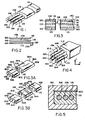
- Figure 1 is a perspective cut-away drawing of a three-fiber sensor device in an enveloping cladding.
- Figure 2 is a schematic side-view diagram of the three fiber cores showing the length differential between the cores.
- Figure 3 shows a longitudinal cross-sectional diagram of the three fiber device showing a method of obtaining an unequal core length.
- Figure 3A shows a perspective diagram of the three fiber device showing another method of obtaining an unequal core length by cleaving the fiber.
- Figure 3B shows a perspective diagram of the three fiber device showing still another method of obtaining an unequal core length.
- Figure 4 is a five-core sensor containing two parasitic cores to eliminate oscillations with unwanted polarizations.
- Figure 5 is a cross-sectional diagram of a vise arrangement used to insure operation at one direction of polarization.
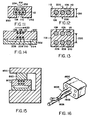
- Figure 6 is a longitudinal cross-sectional view of the three-fiber sensor showing one method of coupling an output fiber to extract output energy.
- Figure 7 is a longitudinal cross-sectional view of a three-fiber sensor showing an alternative method of coupling an output fiber to extract output power.
- Figure 8 is a longitudinal cross-sectional diagram of the three-fiber sensor showing one method of optically pumping the fiber laser cavities using semiconductor laser diodes.
- Figure 9 is a perspective view of an alternative embodiment of the three-fiber sensor including an additional pumping section.
- Figure 10 is a perspective view of a high-power embodiment of the invention utilizing a plurality of pump coupling fibers.
- Figure 11 is a cross-sectional schematic diagram of a method of tuning a three-fiber laser sensor.
- Figure 12 is a schematic diagram of a three-fiber laser sensor being used as a strain gage.
- Figure 13 is a schematic cross-sectional diagram of a six-fiber laser which uses two three-fiber laser sensors in a differential arrangement.
- Figure 14 shows a six-fiber differential laser sensor in an atmosphere pressure gauge.
- Figure 15 is a cross-sectional view of a vise arrangement used to adapt the sensor to measure certain variables.
- Figure 16 is a perspective diagram of a two sensor unit showing the method of combining the outputs to obtain a differential signal.
- Figure 1 shows a perspective schematic diagram of one embodiment of the illustrative sensor in which one
end 101 ofcladding 112 has been cut away to exposefiber cores fiber cores - The two outer cores, 106 and 110, are doped with a laser-active material such as Neodymium, Erbium or Holmium in accordance with conventional techniques to produce a doped-glass laser-active fiber. The
ends 100 and 104 (and the corresponding other fiber ends atend 114 of the device, not shown in Figure 1) ofcores cores - Each of
cores central core 108. In particular, the cores are positioned about one core diameter from each other. When cores are contained in a common cladding, light will be able to pass radially out of one core into a nearby core. Such a coupling scheme is described in more detail in my U.S. patent no. 4,315,666, issued February 16, 1982 and entitled Coupled Communications Fibers , which patent is hereby incorporated by reference. - Light is coupled from
cores core 108.Core 108 may be comprised of doped or non-doped glass, but at least one end 102 (or the other corresponding end at device end 114) is not mirrored and therefore light which enterscore 108 is lost from the sensor device. - The spacing of
cores core 108 is such that each resonant cavity loses an appreciable fraction of its power to thecentral core 108 during each traverse of the light through the optical cavity. Sincecore 108 constitutes a loss source, both cavities will experience a loss under most conditions of operation. - However, if the two resonant cavities have a common resonance frequency and are 180° out of phase then there will be very little net transfer of energy to the
central core 108 from either cavity and, thus, neither cavity will experience a loss. - In general, a laser cavity will preferentially oscillate at a frequency at which the overall gain is maximized (the overall, or net, gain is the product of the laser gain and the cavity gain where the cavity gain is defined as "1" minus the cavity round trip loss). Accordingly, if both of the sensor resonant cavities are optically pumped, they will both resonate at a common resonance frequency under the doping gain curve which is common to both cavities.
- In order to select a single frequency, it is necessary to make the two resonant cavities slightly different. In particular, the difference is such to make the spacing between the multiple resonant orders slightly different between the two cavities. When this is done, the two cavities are "Vernier-tuned" and will have a common resonant frequency and then an extended free spectral range before the next common frequency. If the difference between the cavities is slight, then the spacing between common resonant frequencies will be large and accordingly, if one common frequency falls under the maximum of the gain curve, the next common frequency on either side of that frequency will fall at a region in which the gain curve is substantially down from its maximum. Accordingly, the cavities will preferentially oscillate at the one predetermined frequency nearest the peak gain.
- In order to make the two resonant cavities slightly different, the path length of one is increased relative to the other. In order for the device to operate properly, it is necessary for the three fibers to be phase-matched and, thus, the difference in optical path length should be obtained by having one cavity slightly longer than the other instead of having a differential phase velocity. Such a construction is shown in Figure 2 in which
core 110 extends ashort distance 130 beyondcores distance 130 is 0.1% - 1% of the total length of the cores. - In an embodiment shown as Figure 1 in which the three cores are contained in a common cladding, the difference in optical path length may be achieved by several methods. In one embodiment, one end of the fiber may be cut and polished at an angle as shown in Figure 3 in which end 132 has been cut at an angle. At
end 132, if thesurface 114 were simply mirrored to provide the mirrors for the optical cavities, the mirrors would be at an angle with respect to the axis of the fiber and would reflect light at an unacceptable angle to the core axis. Therefore, it is necessary to use twofittings - In another, preferred embodiment, as shown in Figure 3A, the difference in optical path length between the two resonant cavities is achieved by cleaving a piece of
composite fiber 350 containing multiple cores 106-110. The two surfaces, 360 and 362, formed by the cleave are polished and amirror surface 352 is applied toresonant cavity fiber 106 at thecleaved end 360. As is well-known, themirror surface 352 should cover more than just the end of thefiber core 106 since some light travels outside the core. More specifically, as a general approximation, a mirror should cover an area with a diameter twice the core diameter (the mirror area should be increased if very high reflectivity is required and may be decreased if high reflectivity is not required). Alternatively, the entirecleaved end 360 may be mirrored and, subsequently, the mirror coating can be removed from cavity fiber core ends 108 and 110 by using conventional methods (for example, a focussed laser beam can be used to blow away the coating). - The two
pieces piece 350 and about .01 centimeter for piece 351) and the cut ends 363 and 366 are polished. The cut ends 363 and 366 can be completely mirrored except for at least one end of thecentral fiber core 108. Alternatively, amirror 358 can be applied only to the cut end offiber core 110. Mirrors are also applied to the cut ends 354 and 356 offiber cores fiber pieces - In an additional embodiment shown in Figure 3B, the desired difference in optical length in the resonant cavities can be achieved by cleaving the composite structure twice as shown in Figure 3B to produce three pieces, 400-404. The ends 400 and 404 differ in length (in an illustrative embodiment, ends 400 and 404 differ in length by approximately .01 centimeters and are each about 0.1 centimeters long and the
center section 402 is about 0.8 centimeters long; in Figure 3B, the center section is shown broken to compress the Figure). The cleaved surfaces, 420-426, are polished as with the previous embodiment. Mirrors are applied tocore end 106 on cleaved surface 420 (mirror 412) and oncore 110 on surface 424 (not shown). Thesurfaces fiber core 110 at surface 432 (mirror 410) and tofiber core 106 at surface 430 (not shown). The cleaved pieces are then aligned and glued together to produce a composite structure in which the two cavities have slightly different path lengths and are offset. The offset allows for easier tuning of the structure which will be described in detail hereinafter. - In order to maintain a single resonant frequency, it is desirable to maintain oscillation with constant polarization because a change in polarization effectively introduces a change in the optical path length which causes a shift in frequency. One way to ensure oscillation with constant polarization is to fabricate the device with three fiber cores consisting of identical birefringent fibers. In such a construction the condition for resonance is different in the two resonant cavities for the two polarization states and it is unlikely that the two common resonance frequencies that result from the two polarization states would both occur near each other. With such an arrangement it is highly likely that the device will oscillate with an output having one or the other of the principal axes of polarization.
- In cases where oscillation must be confined to a single axis of polarization, several methods can be used to eliminate oscillation on one of the axes. For example, two parasitic cores can be added as shown in Figure 4. In Figures 4,
cores cores Cores cores cores cores cores - In operation, the
ends fibers 150 and 152 (and the corresponding opposite ends) are not reflective so that any light coupled into the fibers is lost to the device. Sincefibers fibers fibers - For example, in a preferred embodiment, if both oscillation cavities are doped with Neodymium, the device can be made to oscillate at the 1.3 micron laser region of Neodymium instead of the 1.05 micron region although the 1.05 micron region has greater gain. This can be accomplished by making
cores cores cores cores - The same result can be achieved in an alternative embodiment by using multi-layered dielectric mirrors on at least one end of
fibers 106 and 110 (for example, ends 100 and 104 or the opposite ends, not shown in Figure 4). In accordance with well-known construction, dielectric mirrors can be "tuned" to be highly-reflective to energy in a particular narrow wavelength range and to have low-reflectivity for wavelengths outside the tuned range. Accordingly, in the example given above, multi-layered dielectric mirrors can be used which are "tuned" to a narrow wavelength range including 1.3 microns and to have high-reflectivity for wavelengths in these regions. If the mirrors have a low reflectivity at a wavelength of 1.05 microns, then the device will preferentially oscillate at 1.3 microns. - Still another method of achieving operation with oscillation on a single axis of polarization is shown in Figure 5. In this embodiment, the sensor unit consisting of cores 106-110 enclosed in
cladding 112, is positioned in avise 162. Located along one side of the sensor is aplastic layer 160. The sensor physical dimensions are such thatplastic 160 is located within one core diameter of cores 106-110.Vise 162 applies pressure toplastic layer 160 raising its index of refraction for the electric vector polarized perpendicular to its surface. If enough pressure is applied to raise the index of refraction of the plastic to be equal to the index of refraction of the cores 106-110, a fraction of the power developed in thecores - It is also possible to replace
vise 162 and plastic 160 with a birefringent crystalline material. In this embodiment, the crystalline material is placed against one side of the sensor device in the position ofplastic 160 in Figure 5 and operates in an analogous fashion. - Still another method of selecting polarization direction is to use a polarizing dielectric mirror on at least one end face of the resonant cavities. Such a mirror is well-known in construction and has greater reflectivity in one plane of polarization.
- Power can be extracted from the laser sensor in a variety of methods. If dielectric mirrors are used, then the mirrors located at one end of one or both resonant cores can be made less than 100% reflective and an output fiber can be butt-coupled to that mirror to extract energy. For example, as shown in Figure 6, the mirror at
face 104 ofcore 110 is a dielectric mirror which has less than 100% reflectivity. Anoptical fiber 165 is butt-coupled to that mirror in a conventional manner. Thus, a small fraction of the power which is developed incore 110 is transferred tofiber 165 through which the power can be transmitted to a detector. - In an alternative embodiment, as shown in Figure 7, an
optical fiber 165 can be butt-coupled to oneface 102 of thecentral core 108. It is possible to arrange for unequal transfer of energy between the resonant fibers and the central fiber to insure that net energy will be transferred to the central fiber. For example, if oneresonant fiber transfers 10% of its energy to the central core, but the other resonant fiber transfers 20% of its energy the central fiber, then a substantial fraction of the total energy will always be transferred to the central core. Such an unequal transfer can be arranged by adjusting the spacing of the resonant. cores relative to the central core. In a similar manner one resonant cavity core can receive more pump power to insure that more energy will be transferred to the central core and accomplish the same result. - In order to produce lasing action, the two
resonant cavities semiconductor laser diodes ends cores cores - An alternative and preferred construction for optically pumping the resonant cores is shown in Figure 9. The three
fiber cores common cladding 112 as with the previous embodiments. However, surrounding fibers 106-110 is an additional light-conducting "pump"region 180 which is constructed of a material of which the index of refraction is chosen to lie between the indices of refraction of cores 106-110 andcladding 112. More specifically, the index of refraction of the material comprising cores 106-110 is higher than the index of refraction ofpump region material 180 which is, in turn, higher than the index or refraction ofcladding material 112. With this construction, light may be injected into the end of the pump region by coupling a laser diode to it in a conventional fashion. The light injected into the end ofregion 180 can enter cores 106-110, but cannot enter cladding 112 (in accordance with well-known numerical aperture considerations). - The construction shown in Figure 9 is particularly advantageous because the pump light enters the cores laterally and in long lasers, a large cross-section for light injection is provided. This large cross-section allows use of a laser diode pump with a large cross section and hence high power output.
- In the case of a long laser oscillator or laser amplifier, the secondary
pump conduction region 180 can be utilized to allow pumping with a very high pump power by using a plurality of pump couplers as shown in Figure 10. - In the construction shown in Figure 10, the basic three-core sensor with the
additional pumping region 180 is used with the exception that the top of the unit is ground away to expose aflat portion 185. Mounted on the flat portion are a plurality ofpump coupler fibers 190. Each of the pump coupler fibers comprises a core 195 which is ground to a flat 197. A laser diode with the appropriate output frequency is coupled to theflat portion 197 and transmits pump power down thefibers 190 to thepump conduction region 180 which surrounds sensor cores 106-110. After the laser diodes have been mounted, the entire device would be protected by encasing it in a plastic compound which has an index of refraction that is equal to, or less than, the index of refraction of thecladding material 112. In addition, the encasing plastic material would be chosen to have low absorption at the pump wavelength to conserve pump energy. - Figure 11 shows a method of tuning the sensor to operate at a preferred wavelength. The sensor structure, consisting of cores 106-110 surrounded by cladding 112 is placed in two
vises electric pads cavity cores - The illustrative embodiment shown in Figure 3B is particularly suited to tuning by using the piezo-electric clamps discussed above. With this embodiment the piezo-electric clamps are applied to each of
end pieces - The three-core device can be used as a sensor because the output frequency of the laser oscillations is sensitive to changes in the optical path length of the resonant cavities. In particular, the optical path length depends on a number of factors including temperature and pressure. Thus, the sensor can be used to directly sense such variables and convert them into frequency changes which can be easily processed by conventional digital circuitry.
- For example, in a typical device of length 1 cm using cores comprised of Neodymium-doped glass of diameter 5 microns, the optical path length of the resonant cavity changes by an order of magnitude of 10-5 for each 1°C temperature change of the cavities. A typical optical output frequency using Neodymium-doped glass is on the order of 3x10 14 Hertz and therefore a 1° change in the optical cavity temperature produces an output frequency change in the order of 3×10⁹ Hertz.
- The three-fiber laser sensor can also be used as a strain gauge as shown in Figure 12. If the strain is applied to the sensor in the direction of
arrows 200 it appears as a lateral compression of the device. In this case, a change in the thickness of the device of approximately .001% (10-5) will produce an optical frequency shift on the output resonant frequency on the order of 3×10⁹ Hertz. A typicallateral dimension 210 as shown in Figure 12 is approximately 100 microns and thus a compression of 10-3 microns or 10 Angstroms will produce a 3×10⁹ Hertz shift in the output frequency. Thus, in principle, it would be possible to measure a compression of the device on the order of 10-12 microns, if it were possible to measure a frequency change of 1 Hertz. With conventional digital processing technology such a measurement can be made if the observation is made over a 1 second time interval, As a practical matter, however, the measurement of such small size changes is limited by thermal noise and well-known quantum-mechanical effects. - In order to reduce effects caused by changes in extraneous environmental parameters (such as vibration), it is desirable to use a dual sensor arrangement such as that shown in a cross-sectional view in Figure 13. In this arrangement, two sensors consisting of cores 106-110 and cores 206-210, respectively, are used. The two sensors each operate in the manner previously described. The
separation distance 220 between cores 106-110 and cores 206-210 is sufficient to prevent a substantial amount of coupling of light between the cores of the separate oscillators, but since the sensors units are physically spaced closely together, they will experience nearly the same temperature and pressure. - In the preferred embodiment, the outputs from the two sensors are combined and directed into one single-mode optical fiber. This combination can be accomplished by using a 50% phase-matched lateral coupler such that that shown in Figure 16. In Figure 16, a two
sensor unit device 1600 has twooutput fibers fibers -
Fibers area 1606 by removing a portion of the cladding and placing the fibers together longitudinally in a conventional manner to construct the coupler.Fiber 1602 transmits the combined signal to a photodetector which responds to the "beat" or difference frequency. In this manner, in order to obtain a differential output, it is not necessary to accurately count two high-frequency signals and then subtract them. Instead, the signals are subtracted first and then counted. Using the foregoing construction and operation, it is possible to detect difference frequencies of one cycle per second. Since only the difference of the two sensor signals is used in further processing, the effects of unwanted variables are cancelled in the output signal. - It is possible to construct the two sensors from different materials in order to selectively measure certain variables. More specifically, if the fiber core composition of the two sensors is different, then the two sensors will react differently to a particular variable. For example, if the glass composition used in the cores of one sensor has a slightly different temperature coefficient of index of refraction from the glass composition used in the cores of the other sensor, then a temperature difference can be measured. More specifically, if with the latter construction, the two sensors produce the same output optical frequency at temperature To, then at temperature To plus a small increment T the sensors will produce output frequencies that differ by amount proportional to
- T and to dn/dT (where dn/dT is the change in the index of refraction with temperature and dn/dT is the difference in temperature coefficients between the two materials).
- An embodiment of the device which can be used to measure pressure is shown in a cross-sectional view in Figure 14. Here a dual sensor construction is embedded in
bar 300.Bar 300 is mated withchannel 302 to produce aspace 304 which is closed to the atmosphere (panels, not shown in Figure 14, close the ends of the channel). The construction shown in Figure 14 can be fabricated from two separate pieces which are subsequently glued or fused together or the entire construction can be drawn from a common preform as one piece. - A change in atmospheric pressure produces a differential pressure between the outside atmosphere and the gas trapped in
space 304. This pressure differential tends to bendmember 300 either toward or away from thepressure chamber 304. Assume for the moment that themember 300 bends toward thepressure chamber 304. Such a motion places the upper sensor (consisting of cores 106-110) under compression in the direction ofarrow 400 and the lower sensor (consisting of cores 206-210) under tension in the direction ofarrow 400. If the two sensors are designed (as discussed previously) to oscillate with the electric polarization vector the direction ofarrow 400, then a frequency shift will be developed between the two sensors which can be detected by monitoring the beat frequency between the two devices. If the device shown in Figure 14 is constructed with all cores comprised of the same material, then temperature effects on the two sensors will be approximately the same and the device will only be sensitive to pressure and insensitive to temperature. - In a similar manner, by proper choice of materials it is possible to sense changes in other variables. Where no choice of materials produces an adequate sensitivity to a desired variable, the device can be used to sense the variable indirectly. For example, it is possible to measure magnetic field strength by using the arrangement shown in Figure 15. The heart of the device is a dual-sensor arrangement 800 similar to that described with respect to Figure 14 with the exception that the
cavity 304 in Figure 14 is allowed to communicate with the atmosphere to eliminate pressure effects. The dual-sensor arrangement 800 is placed in avise 850 with a piece ofmagnetostrictive material 860 located above the sensor area. When the device is placed in a magnetic field, the field produces dimensional changes in the magnetostrictive material in accordance with well-known physical principles. In particular. the material changes thickness in an amount which is proportional to the applied field and the expansion in turn applies a stress to the sensors 800 which can be detected in the manner previously described. - Where the operating environment of the sensors has more than one parameter which tends to effect the sensors in addition to the desired variable, three or more sensors may be used in close proximity to sense various variables. The outputs of the sensors can be mixed into several single mode fibers and different combinations of the signals separately detected in order to produce output signals which selectively measure the desired variable. The various beat frequencies developed by the sensors can be used to generate a "matrix" of signals from which the value of the desired parameters can be determined.
- In order to detect changes in monitored variables the sensor can be "tuned" by attaching a piezo-electric device to the sensor. The piezo-electric device squeezes the sensor in response to an applied voltage to produce a change in its output frequency. The tuning apparatus can be used in a two-sensor arrangement to produce a zero beat frequency (a null signal) at the output to the detector. Thus, the voltage required to produce the zero beat frequency or null response is a measure of the sensed parameter. The precision of the device is thereby limited to the accuracy with which the voltage required to produce a zero frequency output can be measured. Instead of the latter arrangement a hybrid scheme in which both an applied voltage and a nonzero beat frequency are monitored can be used.
- Alternatively, the output signal from a measuring sensor can be beat against another oscillator which is external to the device. The device will operate satisfactorily if the external comparison frequency is known and not subject to unknown variations resulting from environmental changes. For example, it is possible to use the double oscillator as shown in Figure 14 (in addition to beating the output frequencies of the two sensors against each other) by beating the output of the top sensor or the bottom sensor against an external frequency source. In this way it is possible to read both temperature and pressure from the device.
- If the sensor output is being beat against a reference frequency which is controllable and where an environmental parameter of relatively high frequency is to be detected (for example, a sonic wave with a frequency of 10,000 Hertz) it may be difficult to detect the beat frequency when the intensity of the sonic wave is not sufficient to compress the sensor so that the optical output frequency is changed at least 10,000 Hertz. Specifically, the number of optical frequency cycles which occur between each sound cycle is related inversely to the sound intensity and to the sound frequency. Under certain conditions the number of optical frequency cycles may fall to less than one cycle per sound cycle and, accordingly, detection by counting fails.
- In order to detect the high-frequency environmental parameter described above, the reference frequency is increased (illustratively, for the example given above to 20,000 Hertz) and detection is accomplished by measuring the time interval between beats of the optical frequencies produced by the sensor unit and the reference frequency source (thus, for the sonic wave example, on the "high" side of the sound pressure cycle, the beats will occur slightly closer in time, while on the "low" side of the sound cycle the beats will occur slightly further apart in time). By this means the sensitivity of the device can be increased because, if photon statistics allow, the time difference between beats can relatively easily be measured to within an accuracy of 1/1000 of a beat interval or less.
Claims (17)
Priority Applications (1)
| Application Number | Priority Date | Filing Date | Title |
|---|---|---|---|
| AT86306088T ATE61877T1 (en) | 1985-08-06 | 1986-08-06 | FIBEROPTIC LASER SENSOR. |
Applications Claiming Priority (2)
| Application Number | Priority Date | Filing Date | Title |
|---|---|---|---|
| US763126 | 1985-08-06 | ||
| US06/763,126 US4730886A (en) | 1985-08-06 | 1985-08-06 | Fiber laser sensor |
Publications (3)
| Publication Number | Publication Date |
|---|---|
| EP0212915A2 true EP0212915A2 (en) | 1987-03-04 |
| EP0212915A3 EP0212915A3 (en) | 1988-01-27 |
| EP0212915B1 EP0212915B1 (en) | 1991-03-20 |
Family
ID=25066948
Family Applications (1)
| Application Number | Title | Priority Date | Filing Date |
|---|---|---|---|
| EP19860306088 Expired - Lifetime EP0212915B1 (en) | 1985-08-06 | 1986-08-06 | Fiber laser sensor |
Country Status (4)
| Country | Link |
|---|---|
| US (1) | US4730886A (en) |
| EP (1) | EP0212915B1 (en) |
| AT (1) | ATE61877T1 (en) |
| DE (1) | DE3678227D1 (en) |
Cited By (9)
| Publication number | Priority date | Publication date | Assignee | Title |
|---|---|---|---|---|
| GB2313662A (en) * | 1996-04-23 | 1997-12-03 | R D P Electronics Limited | Optical transducer |
| GB2323161A (en) * | 1997-03-10 | 1998-09-16 | R D P Electronics Limited | Laser cavity optical transducer |
| US9091785B2 (en) | 2013-01-08 | 2015-07-28 | Halliburton Energy Services, Inc. | Fiberoptic systems and methods for formation monitoring |
| US9557439B2 (en) | 2014-02-28 | 2017-01-31 | Halliburton Energy Services, Inc. | Optical electric field sensors having passivated electrodes |
| US9575209B2 (en) | 2012-12-22 | 2017-02-21 | Halliburton Energy Services, Inc. | Remote sensing methods and systems using nonlinear light conversion and sense signal transformation |
| US9651706B2 (en) | 2015-05-14 | 2017-05-16 | Halliburton Energy Services, Inc. | Fiberoptic tuned-induction sensors for downhole use |
| US9952346B2 (en) | 2013-11-26 | 2018-04-24 | Halliburton Energy Services, Inc. | Fiber optic magnetic field sensing system based on lorentz force method for downhole applications |
| US10241229B2 (en) | 2013-02-01 | 2019-03-26 | Halliburton Energy Services, Inc. | Distributed feedback fiber laser strain sensor systems and methods for subsurface EM field monitoring |
| US10711602B2 (en) | 2015-07-22 | 2020-07-14 | Halliburton Energy Services, Inc. | Electromagnetic monitoring with formation-matched resonant induction sensors |
Families Citing this family (14)
| Publication number | Priority date | Publication date | Assignee | Title |
|---|---|---|---|---|
| US5096277A (en) * | 1982-08-06 | 1992-03-17 | Kleinerman Marcos Y | Remote measurement of physical variables with fiber optic systems |
| US4886333A (en) * | 1985-08-06 | 1989-12-12 | Hicks John W | Fiber laser sensor |
| WO1989004502A1 (en) * | 1987-11-09 | 1989-05-18 | Hicks John W | Fiber laser sensor |
| IT1215681B (en) * | 1988-01-12 | 1990-02-22 | Pirelli General Plc | AMPLIFICATION OF OPTICAL SIGNALS. |
| US4955685A (en) * | 1989-02-21 | 1990-09-11 | Sun Microsystems, Inc. | Active fiber for optical signal transmission |
| US5074642A (en) * | 1989-11-14 | 1991-12-24 | Hicks John W | Multifiber endoscope with fibers having different indices of refraction |
| FR2683053B1 (en) * | 1991-10-29 | 1994-10-07 | Thomson Csf | OPTICAL FIBER AND MANUFACTURING METHOD. |
| US5317575A (en) * | 1992-12-11 | 1994-05-31 | Alliedsignal Inc. | System for determining birefringent axes in polarization-maintaining optical fiber |
| KR960015900B1 (en) * | 1993-04-22 | 1996-11-23 | 국방과학연구소 | Polarimetric fiber laser sensor |
| US5778016A (en) * | 1994-04-01 | 1998-07-07 | Imra America, Inc. | Scanning temporal ultrafast delay methods and apparatuses therefor |
| KR0173434B1 (en) * | 1996-02-12 | 1999-04-01 | 윤덕용 | Interferometric Laser Sensor |
| JP5862131B2 (en) * | 2011-09-09 | 2016-02-16 | 富士通株式会社 | Optical amplifier |
| JP5842556B2 (en) * | 2011-11-11 | 2016-01-13 | 住友電気工業株式会社 | Bi-directional optical communication method and multi-core optical fiber |
| US20140241681A1 (en) * | 2013-02-22 | 2014-08-28 | Weatherford/Lamb, Inc. | Multi-core optical waveguide for multi-parameter sensing |
Citations (5)
| Publication number | Priority date | Publication date | Assignee | Title |
|---|---|---|---|---|
| WO1981002955A1 (en) * | 1980-04-05 | 1981-10-15 | Eltro Gmbh | Hybrid laser |
| US4315666A (en) * | 1979-03-19 | 1982-02-16 | Hicks Jr John W | Coupled communications fibers |
| WO1983002855A1 (en) * | 1982-02-16 | 1983-08-18 | United Technologies Corp | Sure-start waveguide laser |
| GB2118765A (en) * | 1982-04-14 | 1983-11-02 | Oudar Jean Louis | Bistable optical device |
| FR2533714A1 (en) * | 1982-09-28 | 1984-03-30 | Thomson Csf | NON-LINEAR INTEGRATED OPTICAL COUPLER DEVICE AND PARAMETRIC OSCILLATOR COMPRISING SUCH A DEVICE |
Family Cites Families (11)
| Publication number | Priority date | Publication date | Assignee | Title |
|---|---|---|---|---|
| US4044315A (en) * | 1962-01-16 | 1977-08-23 | American Optical Corporation | Means for producing and amplifying optical energy |
| US3372969A (en) * | 1963-12-06 | 1968-03-12 | American Optical Corp | High resolution filter for laseremissive energy |
| US3622911A (en) * | 1968-12-02 | 1971-11-23 | Bell Telephone Labor Inc | Laser oscillator with mode selector |
| US3663890A (en) * | 1970-04-27 | 1972-05-16 | Union Carbide Corp | Two cavity laser |
| JPS579041B2 (en) * | 1974-11-29 | 1982-02-19 | ||
| US4068191A (en) * | 1975-08-22 | 1978-01-10 | Gte Laboratories Incorporated | Acoustooptic modulator for optical fiber waveguides |
| US4342499A (en) * | 1979-03-19 | 1982-08-03 | Hicks Jr John W | Communications tuning construction |
| US4531811A (en) * | 1979-03-19 | 1985-07-30 | Polaroid Corporation | Fiber optics polarizer |
| US4546476A (en) * | 1982-12-10 | 1985-10-08 | The Board Of Trustees Of The Leland Stanford Junior University | Fiber optic amplifier |
| US4592043A (en) * | 1983-07-08 | 1986-05-27 | At&T Bell Laboratories | Wavelength division multiplexing optical communications systems |
| US4553238A (en) * | 1983-09-30 | 1985-11-12 | The Board Of Trustees Of The Leland Stanford University | Fiber optic amplifier |
-
1985
- 1985-08-06 US US06/763,126 patent/US4730886A/en not_active Expired - Fee Related
-
1986
- 1986-08-06 DE DE8686306088T patent/DE3678227D1/en not_active Expired - Fee Related
- 1986-08-06 AT AT86306088T patent/ATE61877T1/en active
- 1986-08-06 EP EP19860306088 patent/EP0212915B1/en not_active Expired - Lifetime
Patent Citations (5)
| Publication number | Priority date | Publication date | Assignee | Title |
|---|---|---|---|---|
| US4315666A (en) * | 1979-03-19 | 1982-02-16 | Hicks Jr John W | Coupled communications fibers |
| WO1981002955A1 (en) * | 1980-04-05 | 1981-10-15 | Eltro Gmbh | Hybrid laser |
| WO1983002855A1 (en) * | 1982-02-16 | 1983-08-18 | United Technologies Corp | Sure-start waveguide laser |
| GB2118765A (en) * | 1982-04-14 | 1983-11-02 | Oudar Jean Louis | Bistable optical device |
| FR2533714A1 (en) * | 1982-09-28 | 1984-03-30 | Thomson Csf | NON-LINEAR INTEGRATED OPTICAL COUPLER DEVICE AND PARAMETRIC OSCILLATOR COMPRISING SUCH A DEVICE |
Non-Patent Citations (3)
| Title |
|---|
| 3rd INTERNATIONAL CONFERENCE ON OPTICAL FIBER SENSORS, Digest of Technical Papers, San Diego, California, 13th-14th February 1985, pages 142,143; G. MELTZ et al.: "Twin-core fiber-optic strain and temperature sensor"; M. JOHNSON: "Differential, reflective fiber displacement sensor with misalignment compensation" * |
| APPLIED PHYSICS LETTERS, vol. 44, no. 4, February 1984, pages 368-370, American Institute of Physics, New York, US; L.A. COLDREN et al.: "Continuous operation of monolithic dynamic-single-mode coupled-cavity lasers" * |
| RADIO ENGINEERING AND ELECTRONIC PHYSICS, vol. 15, no. 7, July 1970, pages 1249-1251, Washington, D.C., US; KH.I. GAPRINDASHVILI et al.: "Coupled fiber lasers" * |
Cited By (10)
| Publication number | Priority date | Publication date | Assignee | Title |
|---|---|---|---|---|
| GB2313662A (en) * | 1996-04-23 | 1997-12-03 | R D P Electronics Limited | Optical transducer |
| GB2313662B (en) * | 1996-04-23 | 2000-04-12 | R D P Electronics Limited | Optical transducer and method |
| GB2323161A (en) * | 1997-03-10 | 1998-09-16 | R D P Electronics Limited | Laser cavity optical transducer |
| US9575209B2 (en) | 2012-12-22 | 2017-02-21 | Halliburton Energy Services, Inc. | Remote sensing methods and systems using nonlinear light conversion and sense signal transformation |
| US9091785B2 (en) | 2013-01-08 | 2015-07-28 | Halliburton Energy Services, Inc. | Fiberoptic systems and methods for formation monitoring |
| US10241229B2 (en) | 2013-02-01 | 2019-03-26 | Halliburton Energy Services, Inc. | Distributed feedback fiber laser strain sensor systems and methods for subsurface EM field monitoring |
| US9952346B2 (en) | 2013-11-26 | 2018-04-24 | Halliburton Energy Services, Inc. | Fiber optic magnetic field sensing system based on lorentz force method for downhole applications |
| US9557439B2 (en) | 2014-02-28 | 2017-01-31 | Halliburton Energy Services, Inc. | Optical electric field sensors having passivated electrodes |
| US9651706B2 (en) | 2015-05-14 | 2017-05-16 | Halliburton Energy Services, Inc. | Fiberoptic tuned-induction sensors for downhole use |
| US10711602B2 (en) | 2015-07-22 | 2020-07-14 | Halliburton Energy Services, Inc. | Electromagnetic monitoring with formation-matched resonant induction sensors |
Also Published As
| Publication number | Publication date |
|---|---|
| EP0212915A3 (en) | 1988-01-27 |
| DE3678227D1 (en) | 1991-04-25 |
| ATE61877T1 (en) | 1991-04-15 |
| EP0212915B1 (en) | 1991-03-20 |
| US4730886A (en) | 1988-03-15 |
Similar Documents
| Publication | Publication Date | Title |
|---|---|---|
| EP0212915B1 (en) | Fiber laser sensor | |
| US4886333A (en) | Fiber laser sensor | |
| US4758087A (en) | Fiber optic transducer | |
| CA1247421A (en) | Fiber optic interferometer transducer | |
| US4775214A (en) | Wavelength coded resonant optical sensor | |
| US6056436A (en) | Simultaneous measurement of temperature and strain using optical sensors | |
| US6668111B2 (en) | Optical microcavity resonator sensor | |
| US5513913A (en) | Active multipoint fiber laser sensor | |
| US8218916B2 (en) | Fiber optic temperature and pressure sensor and system incorporating same | |
| US4632551A (en) | Passive sampling interferometric sensor arrays | |
| De Brabander et al. | Integrated optical ring resonator with micromechanical diaphragms for pressure sensing | |
| US4577100A (en) | Temperature compensated optical pressure sensor | |
| US7963170B2 (en) | Pressure sensor | |
| WO2002001146A1 (en) | Optical microcavity resonator sensor | |
| KR960015900B1 (en) | Polarimetric fiber laser sensor | |
| Zhao et al. | Ultrasensitive Fabry–Perot strain sensor based on Vernier effect and tapered FBG-in-hollow silica tube | |
| Zhang et al. | High-sensitivity distributed Bragg reflector fiber laser displacement sensor | |
| AU718823B2 (en) | Sensor apparatus with polarization maintaining fibers | |
| WO1989004502A1 (en) | Fiber laser sensor | |
| Sanchez-Gonzalez et al. | Micro-displacement sensor based on hollow core fiber interferometers | |
| EP4073959B1 (en) | Spin-entangled photon emission device | |
| Amorebieta Herrero et al. | Twin-core fiber sensor integrated in laser cavity | |
| Lin et al. | Sensitivity Enhancement of Ultrahigh-Order Mode Based Magnetic Field Sensor via Vernier Effect and Coarse Wavelength Sampling | |
| KR100319537B1 (en) | Fiber optic temperature sensor using evanescent field coupling of the thermo-optic polymer planar waveguide | |
| Grattan et al. | Fibre-Optic Evanescent-Wave Coupling Force Transducer |
Legal Events
| Date | Code | Title | Description |
|---|---|---|---|
| PUAI | Public reference made under article 153(3) epc to a published international application that has entered the european phase |
Free format text: ORIGINAL CODE: 0009012 |
|
| AK | Designated contracting states |
Kind code of ref document: A2 Designated state(s): AT BE CH DE FR GB IT LI LU NL SE |
|
| PUAL | Search report despatched |
Free format text: ORIGINAL CODE: 0009013 |
|
| AK | Designated contracting states |
Kind code of ref document: A3 Designated state(s): AT BE CH DE FR GB IT LI LU NL SE |
|
| 17P | Request for examination filed |
Effective date: 19880713 |
|
| 17Q | First examination report despatched |
Effective date: 19900328 |
|
| DIN1 | Information on inventor provided before grant (deleted) | ||
| RIN1 | Information on inventor provided before grant (corrected) |
Inventor name: HICKS, JOHN WILBUR |
|
| RAP1 | Party data changed (applicant data changed or rights of an application transferred) |
Owner name: AMERICAN MICRO-OPTICAL, INC. |
|
| GRAA | (expected) grant |
Free format text: ORIGINAL CODE: 0009210 |
|
| AK | Designated contracting states |
Kind code of ref document: B1 Designated state(s): AT BE CH DE FR GB IT LI LU NL SE |
|
| REF | Corresponds to: |
Ref document number: 61877 Country of ref document: AT Date of ref document: 19910415 Kind code of ref document: T |
|
| REF | Corresponds to: |
Ref document number: 3678227 Country of ref document: DE Date of ref document: 19910425 |
|
| ITF | It: translation for a ep patent filed |
Owner name: STUDIO TORTA SOCIETA' SEMPLICE |
|
| ET | Fr: translation filed | ||
| PLBE | No opposition filed within time limit |
Free format text: ORIGINAL CODE: 0009261 |
|
| STAA | Information on the status of an ep patent application or granted ep patent |
Free format text: STATUS: NO OPPOSITION FILED WITHIN TIME LIMIT |
|
| 26N | No opposition filed | ||
| PGFP | Annual fee paid to national office [announced via postgrant information from national office to epo] |
Ref country code: FR Payment date: 19920713 Year of fee payment: 7 |
|
| PGFP | Annual fee paid to national office [announced via postgrant information from national office to epo] |
Ref country code: AT Payment date: 19920714 Year of fee payment: 7 |
|
| PGFP | Annual fee paid to national office [announced via postgrant information from national office to epo] |
Ref country code: GB Payment date: 19920715 Year of fee payment: 7 |
|
| PGFP | Annual fee paid to national office [announced via postgrant information from national office to epo] |
Ref country code: SE Payment date: 19920720 Year of fee payment: 7 Ref country code: DE Payment date: 19920720 Year of fee payment: 7 |
|
| PGFP | Annual fee paid to national office [announced via postgrant information from national office to epo] |
Ref country code: CH Payment date: 19920721 Year of fee payment: 7 |
|
| PGFP | Annual fee paid to national office [announced via postgrant information from national office to epo] |
Ref country code: BE Payment date: 19920723 Year of fee payment: 7 |
|
| PGFP | Annual fee paid to national office [announced via postgrant information from national office to epo] |
Ref country code: LU Payment date: 19920804 Year of fee payment: 7 |
|
| PGFP | Annual fee paid to national office [announced via postgrant information from national office to epo] |
Ref country code: NL Payment date: 19920831 Year of fee payment: 7 |
|
| EPTA | Lu: last paid annual fee | ||
| PG25 | Lapsed in a contracting state [announced via postgrant information from national office to epo] |
Ref country code: LU Free format text: LAPSE BECAUSE OF NON-PAYMENT OF DUE FEES Effective date: 19930806 Ref country code: GB Effective date: 19930806 Ref country code: AT Effective date: 19930806 |
|
| PG25 | Lapsed in a contracting state [announced via postgrant information from national office to epo] |
Ref country code: SE Effective date: 19930807 |
|
| PG25 | Lapsed in a contracting state [announced via postgrant information from national office to epo] |
Ref country code: LI Effective date: 19930831 Ref country code: CH Effective date: 19930831 Ref country code: BE Effective date: 19930831 |
|
| BERE | Be: lapsed |
Owner name: AMERICAN MICRO-OPTICAL INC. Effective date: 19930831 |
|
| PG25 | Lapsed in a contracting state [announced via postgrant information from national office to epo] |
Ref country code: NL Effective date: 19940301 |
|
| GBPC | Gb: european patent ceased through non-payment of renewal fee |
Effective date: 19930806 |
|
| NLV4 | Nl: lapsed or anulled due to non-payment of the annual fee | ||
| PG25 | Lapsed in a contracting state [announced via postgrant information from national office to epo] |
Ref country code: FR Effective date: 19940429 |
|
| REG | Reference to a national code |
Ref country code: CH Ref legal event code: PL |
|
| PG25 | Lapsed in a contracting state [announced via postgrant information from national office to epo] |
Ref country code: DE Effective date: 19940503 |
|
| REG | Reference to a national code |
Ref country code: FR Ref legal event code: ST |
|
| EUG | Se: european patent has lapsed |
Ref document number: 86306088.5 Effective date: 19940310 |
|
| PG25 | Lapsed in a contracting state [announced via postgrant information from national office to epo] |
Ref country code: IT Free format text: LAPSE BECAUSE OF NON-PAYMENT OF DUE FEES;WARNING: LAPSES OF ITALIAN PATENTS WITH EFFECTIVE DATE BEFORE 2007 MAY HAVE OCCURRED AT ANY TIME BEFORE 2007. THE CORRECT EFFECTIVE DATE MAY BE DIFFERENT FROM THE ONE RECORDED. Effective date: 20050806 |