EP0211248B1 - Seat adjustment for a motor vehicle - Google Patents
Seat adjustment for a motor vehicle Download PDFInfo
- Publication number
- EP0211248B1 EP0211248B1 EP86109161A EP86109161A EP0211248B1 EP 0211248 B1 EP0211248 B1 EP 0211248B1 EP 86109161 A EP86109161 A EP 86109161A EP 86109161 A EP86109161 A EP 86109161A EP 0211248 B1 EP0211248 B1 EP 0211248B1
- Authority
- EP
- European Patent Office
- Prior art keywords
- backrest
- cushion
- backseat
- seat
- hinge plate
- Prior art date
- Legal status (The legal status is an assumption and is not a legal conclusion. Google has not performed a legal analysis and makes no representation as to the accuracy of the status listed.)
- Expired - Lifetime
Links
Images


Classifications
-
- B—PERFORMING OPERATIONS; TRANSPORTING
- B60—VEHICLES IN GENERAL
- B60N—SEATS SPECIALLY ADAPTED FOR VEHICLES; VEHICLE PASSENGER ACCOMMODATION NOT OTHERWISE PROVIDED FOR
- B60N2/00—Seats specially adapted for vehicles; Arrangement or mounting of seats in vehicles
- B60N2/24—Seats specially adapted for vehicles; Arrangement or mounting of seats in vehicles for particular purposes or particular vehicles
- B60N2/32—Seats specially adapted for vehicles; Arrangement or mounting of seats in vehicles for particular purposes or particular vehicles convertible for other use
- B60N2/36—Seats specially adapted for vehicles; Arrangement or mounting of seats in vehicles for particular purposes or particular vehicles convertible for other use into a loading platform
- B60N2/366—Seats specially adapted for vehicles; Arrangement or mounting of seats in vehicles for particular purposes or particular vehicles convertible for other use into a loading platform characterised by the locking device
-
- B—PERFORMING OPERATIONS; TRANSPORTING
- B60—VEHICLES IN GENERAL
- B60N—SEATS SPECIALLY ADAPTED FOR VEHICLES; VEHICLE PASSENGER ACCOMMODATION NOT OTHERWISE PROVIDED FOR
- B60N2/00—Seats specially adapted for vehicles; Arrangement or mounting of seats in vehicles
- B60N2/02—Seats specially adapted for vehicles; Arrangement or mounting of seats in vehicles the seat or part thereof being movable, e.g. adjustable
- B60N2/0284—Adjustable seat-cushion length
-
- B—PERFORMING OPERATIONS; TRANSPORTING
- B60—VEHICLES IN GENERAL
- B60N—SEATS SPECIALLY ADAPTED FOR VEHICLES; VEHICLE PASSENGER ACCOMMODATION NOT OTHERWISE PROVIDED FOR
- B60N2/00—Seats specially adapted for vehicles; Arrangement or mounting of seats in vehicles
- B60N2/02—Seats specially adapted for vehicles; Arrangement or mounting of seats in vehicles the seat or part thereof being movable, e.g. adjustable
- B60N2/22—Seats specially adapted for vehicles; Arrangement or mounting of seats in vehicles the seat or part thereof being movable, e.g. adjustable the back-rest being adjustable
- B60N2/2245—Seats specially adapted for vehicles; Arrangement or mounting of seats in vehicles the seat or part thereof being movable, e.g. adjustable the back-rest being adjustable provided with a lock mechanism on the upper part of the back-rest
-
- B—PERFORMING OPERATIONS; TRANSPORTING
- B60—VEHICLES IN GENERAL
- B60N—SEATS SPECIALLY ADAPTED FOR VEHICLES; VEHICLE PASSENGER ACCOMMODATION NOT OTHERWISE PROVIDED FOR
- B60N2/00—Seats specially adapted for vehicles; Arrangement or mounting of seats in vehicles
- B60N2/24—Seats specially adapted for vehicles; Arrangement or mounting of seats in vehicles for particular purposes or particular vehicles
- B60N2/30—Non-dismountable or dismountable seats storable in a non-use position, e.g. foldable spare seats
- B60N2/3002—Non-dismountable or dismountable seats storable in a non-use position, e.g. foldable spare seats back-rest movements
- B60N2/3004—Non-dismountable or dismountable seats storable in a non-use position, e.g. foldable spare seats back-rest movements by rotation only
- B60N2/3009—Non-dismountable or dismountable seats storable in a non-use position, e.g. foldable spare seats back-rest movements by rotation only about transversal axis
- B60N2/3011—Non-dismountable or dismountable seats storable in a non-use position, e.g. foldable spare seats back-rest movements by rotation only about transversal axis the back-rest being hinged on the cushion, e.g. "portefeuille movement"
-
- B—PERFORMING OPERATIONS; TRANSPORTING
- B60—VEHICLES IN GENERAL
- B60N—SEATS SPECIALLY ADAPTED FOR VEHICLES; VEHICLE PASSENGER ACCOMMODATION NOT OTHERWISE PROVIDED FOR
- B60N2/00—Seats specially adapted for vehicles; Arrangement or mounting of seats in vehicles
- B60N2/24—Seats specially adapted for vehicles; Arrangement or mounting of seats in vehicles for particular purposes or particular vehicles
- B60N2/30—Non-dismountable or dismountable seats storable in a non-use position, e.g. foldable spare seats
- B60N2/3038—Cushion movements
- B60N2/304—Cushion movements by rotation only
- B60N2/3045—Cushion movements by rotation only about transversal axis
- B60N2/305—Cushion movements by rotation only about transversal axis the cushion being hinged on the vehicle frame
Definitions
- the invention relates to a rear seat for motor vehicles according to the preamble of patent claim 1.
- a known rear seat of this type (GB-A-2 095 984) has a backrest which is articulated with its lower edge to two hinge plates which are supported on the body only via rubber buffers in their rearmost extreme position.
- the backrest can only be moved parallel to itself, which limits the possible variations in the trunk volume.
- the fixation of the lower edge of the backrest should also be unsatisfactory, particularly when the vehicle is subjected to loads in the longitudinal direction.
- the invention has for its object to provide a rear seat for motor vehicles, which offers even more options for adjustment and ensures a secure fixation of the backrest against the body in any set position.
- the hinge plate can be locked in several pivot positions.
- the trunk of the vehicle can be extended forward in small steps.
- the backrest can be fixed securely in any setting, so that heavy objects are safely retained in the trunk even when the vehicle is decelerated to a greater extent. Locking the lower backrest edge in several swivel positions also makes it possible to adjust the seat surface of the vehicle seat very precisely and to suit the comfort requirements in order to adapt to the body size and the physique of the seat user. If the backrest is inclined gently, the seat user can lean back further and, if necessary, also take a sleeping position.
- a preferred further development of the invention is characterized by an upper hinge plate which is pivoted behind the upper edge of the backrest about a pivot axis arranged fixed to the body and which has a guide slot for an upper pivot axis of the backrest.
- FIGS. 7 to 10 show details of an adjustment mechanism for moving and folding up the seat cushion of the rear seat.
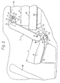
- the rear seats 1 each have a separate seat cushion 4 and a separate backrest 2 or 2 'and are individually adjustable.
- the individual adjustment options are only shown for the front rear seat 1 in FIGS. 1 to 6, whereas the rear rear seat in FIGS. 1 to 6, as can be seen from FIGS. 2 to 6 through its backrest 2 ', the rear seat position from FIG 1 maintains.
- the seat cushions 4 of the rear seats 1 lie lower than the base plate 43 of the loading space 40 of the motor vehicle, which is delimited to the front by the back plate 35 of the backrests 2 of the rear seats 1.
- the backrests 2 are each pivotably articulated about a lower pivot axis 3, which is arranged in the region of the lower edge 30 of the backrests 2, on a hinge plate 5, which in turn is pivotably articulated on a locking plate 7 fixed to the body about a pivot axis 6, which is at a distance is arranged below the lower pivot axis 3 of the backrests 2.
- a laterally projecting upper pivot axis 10 is arranged, which engages in a curved guide slot 12 of an upper hinge plate 11, which in turn is articulated on a body-mounted upper locking plate 25 about the pivot axis 13.
- the upper locking plate 25 also has a plurality of locking holes 26 for locking the upper hinge plate 11 in a plurality of pivot positions by means of a locking bolt 27.
- the seat cushion 4 of the rear seats 1 is with the front lower edge of its bottom plate 28 via a Front pivot axis 14 pivotally articulated on the movable telescopic part 15 of a telescopic rail 15, 16, the fixed telescopic part 16 is fixed to the frame of the rear seats 1, so that the seat cushion 4 of the rear seats 1 can be moved forward independently of their backrests 2 and then with its rear Edge 33 can be folded up against the backrest 38 of the front seat of the motor vehicle (FIG. 6).
- the basic position of the rear seats 1 can be seen from FIG. 1.
- the seat cushion 4 is in its rearmost position.
- the lower hinge plate 5 is pivoted back completely and locked in this position by means of the locking pin 5.
- the upper pivot plate 11 is pivoted completely downwards and locked in this position by means of the locking bolt 27.
- the backrest 2 therefore assumes the rearmost position, in which it rests on the rear edge 33 of the seat cushion 4 and lies inclined obliquely backwards with its back plate 35 against the front edge 42 of the base plate 43 of the loading space 40.
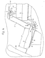
- the backrest 2 of the one rear seat 1 is set steeper than according to FIG. 1, whereas the backrest 2 'of the other rear seat 1 has maintained its basic position.
- the steeper position of the backrest backrest 2 is achieved in that the upper hinge plate 11 after loosening the locking bolt 27 by pulling the upper edge 31 of the backrest 2 pivoted into the top pivot position and there by means of the locking bolt 27 and the top locking hole 26 of the locking plate 25th is locked again.
- the backrest 2 is pivoted about its lower pivot axis 3, the upper pivot axis 10 of the backrest 2 passing through the curved guide slot 12 in the upper hinge plate 11 until it lies against the front end of the guide slot 12.
- the adjustment of the backrest 2 according to FIG. 3 is achieved in that the lower pivot plate 5 is pushed upwards after the locking bolt 9 has been released, whereby the lower pivot axis 3 of the backrest 2 together with its lower one Edge 30 is shifted forward with respect to the seat cushion 4 which maintains its position.
- the lower hinge plate 5 is locked again by inserting the locking bolt 9 into the next locking hole 8 of the locking plate 7.
- the seat cushion 4 which remains at a standstill slides with its guide bolt 24 in the guide slot 23 of the lower hinge plate 5.
- the cargo space 40 as can be seen in FIG.
- the seat depth of the seat cushion 4 is reduced to the dimension T, whereas the inclination of the adjusted backrest 2 again corresponds to that in the basic position from FIG. 1.
- the shortened seat depth T leads, in particular in the case of young vehicle occupants, to them taking a more favorable sitting position. Since at the same time the seat cushion 4 retains its original position, the knee space between the front edge of the seat cushion 4 and the backrest 38 of the front seat in front has remained unchanged.
- the position of the backrest 2 shown in FIG. 5 is suitable for the vehicle occupant to be able to lean back further, for example to assume a sleeping position.
- the full increase in the loading space of the loading space 40 is achieved in that the seat cushion 4 with the backrest 2 in the basic position corresponding to FIG. 1 after its guide bolt 24 has been removed from the guide slot 23 of the lower hinge plate 5 with the aid of Telescopic rail 15, 16 was pushed all the way forward and was then folded up about the front pivot axis 14 against the backrest 38 of the front seat, so that the normally rear edge 33 of the seat cushion lies at the top, after which the backrest 2 after its upper pivot axis 10 has been removed from the upper Hinge plate 11 behind the folded-up seat cushion 4 has been folded down into the horizontal position, in which the base plate 43 of the loading space 40 is extended forwards from the back plate 35 of the backrest 2.
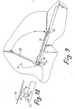
- the details of the telescopic rail 15, 16 and the articulation mechanism of the seat cushion 4 on the movable part 15 of the telescopic rail 16 can be seen from FIGS. 7 to 10.
- the telescopic rail consists of a fixed telescopic part 16, which is fixed to the body-fixed frame of the rear seat, and a movable telescopic part 15 which is displaceable in the fixed telescopic part 16 and at its free end the Bo denplatte 28 of the seat cushion 4 is articulated via a pivot bracket 20, so that the seat cushion 4 can be pivoted up about the pivot axis 14 in the position shown in FIG. Folding up the seat cushion 4 is only possible in the fully extended position of the telescopic rail 15, 16.
- FIG. 1 For this purpose, as can be seen from FIG.
- a locking slot 17 is formed on the top in the longitudinal direction of the telescopic part 16, the front end 17a of which is widened, and is on the underside of the bottom plate 28 of the seat cushion 4 downwardly projecting head pin 18, which normally engages under the edges of the locking slot 17 with its head 19.
- the head bolt 18 can be raised by folding up the seat cushion 4 emerge from the locking slot 17.
- the folded-up seat cushion 4 can be locked in the folded-up position at the front end of the movable telescopic part 15 of the telescopic rail.
- a locking hole 21, 22 is formed in the swivel bracket 20 and at the front end of the movable telescopic part 15.
- the locking holes 21, 22 are arranged so that they overlap each other in the folded-up position of the seat cushion 4, so that a locking bolt (not shown) can be inserted through the locking holes 21, 22, which locks the pivoted-up seat cushion 4.
Landscapes
- Engineering & Computer Science (AREA)
- Aviation & Aerospace Engineering (AREA)
- Transportation (AREA)
- Mechanical Engineering (AREA)
- Seats For Vehicles (AREA)
Description
Die Erfindung bezieht sich auf einen Rücksitz für Kraftwagen nach dem Oberbegriff des Patentanspruchs 1.The invention relates to a rear seat for motor vehicles according to the preamble of patent claim 1.
Ein bekannter derartiger Rücksitz (GB-A-2 095 984) weist eine Rückenlehne auf, die mit ihrem unteren Rand an zwei Scharnierplatten angelenkt ist, die sich nur in ihrer hintersten Extremlage über Gummipuffer an der Karosserie abstützen. Die Rückenlehne ist nur parallel zu sich verlagerbar, was die variationsmöglichkeiten hinsichtlich des Kofferraumvolumens einschränkt. Zum anderen dürfte auch die Fixierung des unteren Randes der Rückenlehne insbesondere bei Belastungen in Längsrichtung des Fahrzeuges unbefriedigend sein.A known rear seat of this type (GB-A-2 095 984) has a backrest which is articulated with its lower edge to two hinge plates which are supported on the body only via rubber buffers in their rearmost extreme position. The backrest can only be moved parallel to itself, which limits the possible variations in the trunk volume. On the other hand, the fixation of the lower edge of the backrest should also be unsatisfactory, particularly when the vehicle is subjected to loads in the longitudinal direction.
Der Erfindung liegt die Aufgabe zugrunde, einen Rücksitz für Kraftfahrzeuge zu schaffen, der noch mehr Möglichkeiten zur Einstellung bietet und in jeder eingestellten Position eine sichere Fixierung der Rückenlehne gegenüber der Karosserie gewährleistet.The invention has for its object to provide a rear seat for motor vehicles, which offers even more options for adjustment and ensures a secure fixation of the backrest against the body in any set position.
Diese Aufgabe wird erfindungsgemäß bei einem Rücksitz für Kraftwagen nach dem Oberbegriff des Patentanspruchs 1 dadurch gelöst, daß die Scharnierplatte in mehreren Schwenklagen arretierbar ist. Auf diese Weise läßt sich in kleinen Schritten der Kofferraum des Fahrzeuges nach vorne erweitern. In jeder Einstellung ist eine sichere Festlegung der Rückenlehne möglich, so daß auch bei stärkeren Verzögerungen des Fahrzeuges schwere Gegenstände sicher im Kofferraum zurückgehalten werden. Das Arretieren des unteren Rückenlehnenrandes in mehreren Schwenklagen ermöglicht es ferner, die Sitzfläche des Fahrzeugsitzes zur Anpassung an die Körpergröße und dem Körperbau der Sitzbenutzer sehr genau und den Komfortansprüchen entsprechend einzustellen. Bei einer flachen Neigung der Rückenlehne kann sich der Sitzbenutzer weiter zurücklehnen und ggf. auch eine Schlafstellung einnehmen.This object is achieved in a rear seat for motor vehicles according to the preamble of claim 1 in that the hinge plate can be locked in several pivot positions. In this way, the trunk of the vehicle can be extended forward in small steps. The backrest can be fixed securely in any setting, so that heavy objects are safely retained in the trunk even when the vehicle is decelerated to a greater extent. Locking the lower backrest edge in several swivel positions also makes it possible to adjust the seat surface of the vehicle seat very precisely and to suit the comfort requirements in order to adapt to the body size and the physique of the seat user. If the backrest is inclined gently, the seat user can lean back further and, if necessary, also take a sleeping position.
Eine bevorzugte Weiterbildung der Erfindung ist durch eine obere Scharnierplatte gekennzeichnet, die hinter dem oberen Rand der Rückenlehne um eine karosseriefest angeordnete Schwenkachse schwenkbar angelenkt ist und die einen Führungsschlitz für eine obere Schwenkachse der Rückenlehne aufweist. Auf diese Weise läßt sich die Neigung der Rückenlehne auch dann noch variieren und das Kofferraumvolumen noch schrittweise erweitern, wenn der untere Rand der Rückenlehne schon in einer vorderen Stellung ist.A preferred further development of the invention is characterized by an upper hinge plate which is pivoted behind the upper edge of the backrest about a pivot axis arranged fixed to the body and which has a guide slot for an upper pivot axis of the backrest. In this way, the inclination of the backrest can still be varied and the trunk volume can be gradually expanded when the lower edge of the backrest is already in a forward position.
Weitere vorteilhafte Einzelheiten der Erfindung, die Gegenstand von weiteren Unteransprüchen sind, sind im folgenden anhand der Zeichnung dargestellt. Es zeigen die Fig. 1 bis 6 jeweils einen Ausschnitt des lnnenraumes eines Kraftwagens mit dem Rücksitz und dem vorderen Teil des Laderaumes in Seitenansicht bei unterschiedlichen Stellungen des Rücksitzes und die Fig. 7 bis 10 Einzelheiten eines Verstellmechanismus zum Verschieben und Hochklappen des Sitzpolsters des Rücksitzes.Further advantageous details of the invention, which are the subject of further subclaims, are shown below with reference to the drawing. Show it 1 to 6 each show a section of the interior of a motor vehicle with the rear seat and the front part of the loading space in a side view in different positions of the rear seat and FIGS. 7 to 10 show details of an adjustment mechanism for moving and folding up the seat cushion of the rear seat.
Bei der aus den Fig. 1 bis 6 ersichtlichen Ausführungsform weisen die Rücksitze 1 jeweils ein gesondertes Sitzpolster 4 und eine gesonderte Rückenlehne 2 bzw. 2' auf und sind individuell verstellbar. Die einzelnen Verstellmöglichkeiten sind nur für den in den Fig. 1 bis 6 vorderen Rücksitz 1 dargestellt, wohingegen der in den Fig. 1 bis 6 hintere Rücksitz, wie aus den Fig. 2 bis 6 durch seine Rückenlehne 2' ersichtlich, die Rücksitzposition aus Fig. 1 beibehält.In the embodiment shown in FIGS. 1 to 6, the rear seats 1 each have a
Die Sitzpolster 4 der Rücksitze 1 liegen tiefer als die Bodenplatte 43 des von der Rückplatte 35 der Rückenlehnen 2 der Rücksitze 1 nach vorn begrenzten Laderaumes 40 des Kraftwagens. Die Rückenlehnen 2 sind jeweils um eine untere Schwenkachse 3, die im Bereich des unteren Randes 30 der Rückenlehnen 2 angeordnet ist, an einer Scharnierplatte 5 schwenkbar angelenkt, die ihrerseits schwenkbar an einer karosseriefesten Arretierplatte 7 um eine Schwenkachse 6 schwenkbar angelenkt ist, die im Abstand unterhalb der unteren Schwenkachse 3 der Rückenlehnen 2 angeordnet ist. In der Arretierplatte 7 sind mehrere Sperrlöcher 8 zum Arretieren der unteren Scharnierplatte 5 in mehreren Schwenkstellungen mittels eines durch die untere Scharnierplatte 5 und die karosseriefeste Arretierplatte 7 hindurchsteckbarem Sperrbolzens 9 auf einem Kreisbogen um die Schwenkachse 6 der unteren Scharnierplatte 5 verteilt angeordnet. Im Bereich des oberen Randes 31 der Rückenlehnen 2 ist eine seitlich vorstehende obere Schwenkachse 10 angeordnet, die in einen gebogen verlaufenden Führungsschlitz 12 einer oberen Scharnierplatte 11 eingreift, welche ihrerseits an einer karosseriefesten oberen Arretierplatte 25 um die Schwenkachse 13 schwenkbar angelenkt ist. Die obere Arretierplatte 25 weist ebenfalls mehrere Sperrlöcher 26 zur Arretierung der oberen Scharnierplatte 11 in mehreren Schwenkstellungen mittels eines Sperrbolzens 27 auf. Das Sitzpolster 4 der Rücksitze 1 ist mit dem vorderen unteren Rand seiner Bodenplatte 28 über eine vordere Schwenkachse 14 am beweglichen Teleskopteil 15 einer Teleskopschiene 15, 16 schwenkbar angelenkt, deren festes Teleskopteil 16 am Gestell der Rücksitze 1 festgelegt ist, so daß das Sitzpolster 4 der Rücksitze 1 unabhängig von deren Rücklehnen 2 nach vorn verschoben werden kann und dann mit seinem hinteren Rand 33 nach oben gegen die Rückenlehne 38 des Vordersitzes des Kraftwagens hochgeklappt werden kann (Fig. 6). In der Normalstellung des Sitzpolsters 4 greift dieses jedoch mit einem an seinem hinteren Rand 33 seitlich abstehenden Führungsbolzen 24 in einen Führungsschlitz 23 ein, der in der unteren Scharnierplatte 5 entlang eines Kreisbogens verläuft, dessen Krümmungsmittelpunkt in der Schwenkachse 6 der unteren Scharnierplatte 5 liegt.The
Die Grundstellung der Rücksitze 1 ist aus Fig. 1 ersichtlich. Das Sitzpolster 4 befindet sich in seiner hintersten Stellung. Die untere Scharnierplatte 5 ist vollständig zurückgeschwenkt und in dieser Stellung mittels des Sperrbolzens 5 verriegelt. Die obere Schwenkplatte 11 ist vollständig nach unten geschwenkt und in dieser Lage mittels des Sperrbolzens 27 verriegelt. Die Rückenlehne 2 nimmt daher die hinterste Stellung ein, in welcher sie auf dem hinteren Rand 33 des Sitzpolsters 4 aufsitzt und schräg nach hinten geneigt mit ihrer Rückplatte 35 an dem Vorderrand 42 der Bodenplatte 43 des Laderaumes 40 anliegt.The basic position of the rear seats 1 can be seen from FIG. 1. The
Gemäß Fig. 2 ist die Rückenlehne 2 des einen Rücksitzes 1 steiler eingestellt als nach Fig. 1, wohingegen die Rückenlehne 2' des anderen Rücksitzes 1 ihre Grundstellung beibehalten hat. Die steilere Stellung der Rückenlehne kenlehne 2 wird dadurch erreicht, daß die obere Scharnierplatte 11 nach dem Lösen des Sperrbolzens 27 durch Nachvornziehen des oberen Randes 31 der Rückenlehne 2 in die oberste Schwenklage geschwenkt und dort mittels des Sperrbolzens 27 und des obersten Sperrloches 26 der Arretierplatte 25 wieder arretiert wird. Bei dieser Bewegung wird die Rückenlehne 2 um ihre untere Schwenkachse 3 verschwenkt, wobei die obere Schwenkachse 10 der Rückenlehne 2 den gebogenen Führungsschlitz 12 in der oberen Scharnierplatte 11 bis zum Anliegen am vorderen Ende des Führungsschlitzes 12 durchläuft. Durch das Steilerstellen der Rückenlehne 2 des zugeordneten Rücksitzes 1 kann hinter diesen in dem Laderaum 40 z.B. eine hohe Kiste 41 untergebracht werden, die aufgrund ihrer Höhe bei einer Stellung der Rückenlehne 2 nach Fig. 1 nicht weit genug auf der Bodenplatte 43 des Laderaumes 40 hätte nach vorn geschoben werden können, um das Schließen der Heckklappe des Kraftwagens zu ermöglichen. Trotz des Unterbringens der Kiste 41 im Laderaum 40 steht der Rücksitz 1 mit der steiler gestellten Rückenlehne 2 weiterhin als Sitzplatz zur Verfügung.2, the
Aus der Einstellung der Rückenlehne 2 aus Fig. 2 heraus wird die Einstellung der Rückenlehne 2 nach Fig. 3 dadurch erreicht, daß die untere Schwenkplatte 5 nach dem Lösen des Sperrbolzens 9 nach oben geschoben wird wodurch die untere Schwenkachse 3 der Rückenlehne 2 mitsamt deren unterem Rand 30 gegenüber dem seine Lage beibehaltenden Sitzpolster 4 nach vorn verlagert wird. In dieser Lage der unteren Scharnierplatte 5 wird diese durch Einstecken des Sperrbolzens 9 in das nächste Sperrloch 8 der Arretierplatte 7 wieder verriegelt. Während dieser Verstellbewegung der Rückenlehne 2 wird diese um ihre obere Schwenkachse 10 verschwenkt, wohingegen das stehenbleibende Sitzpolster 4 mit seinem Führungsbolzen 24 In dem Führungsschlitz 23 der unteren Scharnierplatte 5 gleitet. In dieser Stellung der Rückenlehne 2 ist der Laderaum 40, wie aus Fig. 3 ersichtlich, zusätzlich vergrößert, so daß beispielsweise zwei längere Kisten 41 in dem Laderaum 40 untergebracht werden können und bis über den vorderen Rand 42 der Bodenplatte 43 des Laderaumes 40 hinaus vorgeschoben werden können. Gleichzeitig aber ist die Sitztiefe des Sitzpolsters 4 auf das Maß T verkürzt, wohingegen die Neigung der verstellten Rückenlehne 2 wieder mit derjenigen in der Grundstellung aus Fig. 1 übereinstimmt. Die verkürzte Sitztiefe T führt insbesondere bei jugendlichen Fahrzeuginsassen dazu, daß diese eine günstigere Sitzposition einnehmen. Da gleichzeitig das Sitzpolster 4 seine ursprüngliche Lage beibehält, ist jedoch der Knieraum zwischen dem vorderen Rand des Sitzpolsters 4 und der Rückenlehne 38 des davorstehenden Vordersitzes unverändert geblieben.From the adjustment of the
Jedoch kann man entsprechend Fig. 4 mit Hilfe der Teleskopschiene 15, 16 nach Lösen einer Verriegelung, die in der Zeichnung nicht dargestellt ist, und nach dem Aushängen des Führungsbolzens 24 aus dem Führungsschlitz 23 der unteren Scharnierplatte 5 das Sitzpolster 4 nach vorne ziehen, so daß die ursprüngliche Sitztiefe T' wieder erreicht ist, entsprechend allerdings auch der Abstand a zwischen dem Sitzpolster 4 und der Rückenlehne 38 des Vordersitzes verkleinert ist.However, according to Fig. 4 with the help of the
Die Sitzeinstellung nach Fig. 5 kann man aus der Grundstellung aus Fig. 1 dadurch erreichen, daß die untere Scharnierplatte 5 in der zu Fig. 3 er - läuterten Weise nach oben geschwenkt wird und dadurch der untere Rand 30 der Rückenlehne 2 gegenüber dem Sitzpolster 4 nach vorn verlagert wird. Da hierbei die obere Scharnierplatte 11 in der Grundstellung verbleibt und die obere Schwenkachse 10 der Rückenlehne 2 zurückhält, gleitet die obere Schwenkachse 10 in dem Führungsschlitz 12 nach unten und dreht sich dabei entsprechend der relativen Schwenkverstellung der Rückenlehne 2 um die obere Schwenkachse 10. Wie aus Fig. 5 ersichtlich, kann in dieser Stellung der Rückenlehne 2 auf der Bodenplatte 43 des Laderaumes 40 ein flaches, aber langes Ladegut 41 untergebracht werden. Unabhängig davon eignet sich jedoch die aus Fig. 5` ersichtliche Stellung der Rückenlehne 2 dazu, daß der Fahrzeuginsasse sich weiter zurücklehnen kann, beispielsweise eine Schlafstellung einnehmen kann.5 can be achieved from the basic position from FIG. 1 by the
In der Stellung des Sitzes nach Fig. 6 ist die volle Laderaumvergrößerung des Laderaumes 40 dadurch erreicht, daß das Sitzpolster 4 bei in der Grundstellung entsprechend Fig. 1 befindlicher Rückenlehne 2 nach Aushängen seines Führungsbolzens 24 aus dem Führungsschlitz 23 der unteren Scharnierplatte 5 mit Hilfe der Teleskopschiene 15, 16 ganz nach vorne geschoben wurde und dann um die vordere Schwenkachse 14 gegen die Rückenlehne 38 des Vordersitzes hochgeklappt wurde, so daß der normalerweise hintere Rand 33 des Sitzpolsters oben liegt, wonach die Rückenlehne 2 nach Aushängen ihrer oberen Schwenkachse 10 aus der oberen Scharnierplatte 11 hinter dem hochgeklappten Sitzpolster 4 bis in die Horizontallage abgeklappt wurde, in welcher von der Rückplatte 35 der Rückenlehne 2 die Bodenplatte 43 des Laderaumes 40 nach vorn verlängert wird. Dadurch kann in dem Laderaum 40 eine hohe und lange Kiste 41 eingeladen werden, die mit ihrem vorderen Ende bis zu der Bodenplatte 28 des hochgeklappten Sitzpolsters 4 reicht. Gleichzeitig jedoch ist der andere Rücksitz erhalten geblieben, was in Fig. 6 durch die Position der Rückenlehne 2' des anderen Rücksitzes dargestellt ist.In the position of the seat according to FIG. 6, the full increase in the loading space of the
Die Einzelheiten der Teleskopschiene 15, 16 und des Anlenkmechanismus des Sitzpolsters 4 an dem beweglichen Teil 15 der Teleskopschiene 16 ist aus den Fig. 7 bis 10 ersichtlich. Die Teleskopschiene besteht aus einem feststehenden Teleskopteil 16, das an dem karosseriefesten Gestell des Rücksitzes festgelegt ist, und aus einem in dem feststehenden Teleskopteil 16 verschiebbaren beweglichen Teleskopteil 15, an dessen freiem Ende die Bo denplatte 28 des Sitzpolsters 4 über eine Schwenklasche 20 angelenkt ist, so daß das Sitzpolster 4 um die Schwenkachse 14 in die Stellung aus Fig. 6 hochgeschwenkt werden kann. Das Hochklappen des Sitzpolsters 4 ist jedoch nur in der voll ausgefahrenen Stellung der Teleskopschiene 15, 16 möglich. Hierzu ist, wie aus Fig. 8 ersichtlich, in dem feststehenden Teleskopteil 16 an der Oberseite ein in Längsrichtung des Teleskopteils 16 verlaufender Verriegelungsschlitz 17 ausgebildet, dessen vorderes Ende 17a verbreitert ausgeführt ist, und ist an der Unterseite der Bodenplatte 28 des Sitzpolsters 4 ein nach unten abstehender Kopfbolzen 18 festgelegt, der mit seinem Kopf 19 die Ränder des Verriegelungsschlitzes 17 normalerweise untergreift. In einer Position der Teleskopschiene 15, 16 und damit des Sitzpolsters 4 jedoch, in welcher der Kopfbolzen 18 beim Ausfahren des beweglichen Teleskopteils 15 aus dem feststehenden Teleskopteil 16 das verbreiterte Ende 17a des Verriegelungsschlitzes 17 erreicht hat, kann der Kopfbolzen 18 durch Hochklappen des Sitzpolsters 4 aus dem Verriegelungsschlitz 17 austreten.The details of the
Wie weiter aus den Fig. 9 und 10 ersichtlich, kann das hochgeklappte Sitzpolster 4 am vorderen Ende des beweglichen Teleskopteils 15 der Teleskopschiene in der hochgeklappten Stellung verriegelt werden. Hierzu ist in der Schwenklasche 20 und am vorderen Ende des beweglichen Teleskopteils 15 je ein Sperrloch 21, 22 ausgebildet. Die Sperrlöcher 21, 22 sind so angeordnet, daß sie einander in der hochgeklappten Stellung des Sitzpolsters 4 überdecken, so daß durch die Sperrlöcher 21, 22 ein Sperrbolzen (nicht gezeigt) gesteckt werden kann, der das hochgeschwenkte Sitzpolster 4 verriegelt.As can further be seen from FIGS. 9 and 10, the folded-up
Wenn auch die Anwendung der Erfindung insbesondere für ein viersitziges Fahrzeug beschrieben wurde, so ist sie trotzdem auch für fünfsitzige Fahrzeuge geeignet.Although the application of the invention has been described in particular for a four-seat vehicle, it is nevertheless also suitable for five-seat vehicles.
Claims (8)
- A backseat for passenger vehicles, especially 4-seater or 5-seater passenger cars, having at least one adjustable backrest (2) the top edge region (31) of which is pivotable about a transverse axis (10) relative to the vehicle body while its bottom edge (30) is movable forward independently of the cushion (4) on the vehicle seat and is pivotable about a bottom transverse axis (3) relative to a hinge plate (5) pivoted to the body, characterised in that the hinge plate (5) is lockable in a number of pivotal positions.
- A backseat according to claim 1, characterised by a top hinge plate (11) which is pivotably mounted behind the top edge (31) of the backrest (2) around a pivot (13) permanently secured to the body and which has a guide slot (12) For a top pivot (10) of the backrest (2).
- A backseat according to claim 2, characterised in that the top pivot (10) of the backrest (2) is releasable from the top hinge plate (11).
- A backseat according to claim 1, characterised in that the cushion (4) of the seat (1) is movable forward independently of the backrest (2).
- A backseat according to claim 4, characterised in that, when the cushion (4) is moved to the front position, its rear edge (33) is pivotable upwards and the backrest (2) is foldable forwards about the bottom pivot (3) behind the upwardly-pivoted cushion (4).
- A backseat according to claim 5, characterised in that the cushion (4) is movably guided by a telescopic rail (15, 16) having a movable telescopic part (15) pivoted to the bottom front edge (34) of the cushion (4) and has a stationary telescopic part (16) formed with a slot (17) for engaging the head (19) of a setbolt (18) which projects from the underside (base plate 28) of the cushion (4) and which can be lifted out of the slot (17) when the cushion (4) is pushed forward.
- A backseat according to claim 6, characterised in that the cushion (4) is lockable at its front edge (36) when in the upwardly-pivoted position.
- A backseat according to any one of claims 1-7 for a 4-seater passenger car having a load space the front of which is bounded by the seats, characterised in that each backseat (1) has a separate backrest (2) and is individually adjustable by adjusting the backrest (2) or the cushion (4).
Applications Claiming Priority (2)
| Application Number | Priority Date | Filing Date | Title |
|---|---|---|---|
| DE19853527152 DE3527152A1 (en) | 1985-07-30 | 1985-07-30 | SEAT ADJUSTMENT IN A VEHICLE |
| DE3527152 | 1985-07-30 |
Publications (3)
| Publication Number | Publication Date |
|---|---|
| EP0211248A2 EP0211248A2 (en) | 1987-02-25 |
| EP0211248A3 EP0211248A3 (en) | 1989-01-04 |
| EP0211248B1 true EP0211248B1 (en) | 1991-02-27 |
Family
ID=6277087
Family Applications (1)
| Application Number | Title | Priority Date | Filing Date |
|---|---|---|---|
| EP86109161A Expired - Lifetime EP0211248B1 (en) | 1985-07-30 | 1986-07-04 | Seat adjustment for a motor vehicle |
Country Status (2)
| Country | Link |
|---|---|
| EP (1) | EP0211248B1 (en) |
| DE (2) | DE3527152A1 (en) |
Cited By (3)
| Publication number | Priority date | Publication date | Assignee | Title |
|---|---|---|---|---|
| US7377584B2 (en) | 2003-07-28 | 2008-05-27 | Johnson Controls Technology Company | Articulating high latch for a seat |
| US8313059B2 (en) | 2001-08-09 | 2012-11-20 | Virgin Atlantic Airways Limited | Seating system and a passenger accommodation unit for a vehicle |
| DE102008049923B4 (en) * | 2008-02-09 | 2014-04-10 | Kokinetics Gmbh | Device for adjusting the seat depth of a vehicle with a seat pan |
Families Citing this family (24)
| Publication number | Priority date | Publication date | Assignee | Title |
|---|---|---|---|---|
| GB2214794A (en) * | 1988-02-13 | 1989-09-13 | Austin Rover Group | A vehicle seat |
| DE4120121A1 (en) * | 1991-05-31 | 1992-12-03 | Hammerstein Gmbh C Rob | VEHICLE SEAT WITH SEAT DEPTH AND BACKREST ADJUSTMENT |
| FR2710883B1 (en) * | 1993-10-08 | 1995-11-17 | Renault | Vehicle rear seat with reclining backrest. |
| DE4437539C2 (en) * | 1993-10-26 | 2003-01-16 | Hammerstein Gmbh C Rob | vehicle seat |
| DE4402978C2 (en) * | 1994-02-01 | 1996-01-18 | Keiper Recaro Gmbh Co | Rear seat back for motor vehicles |
| IT1280853B1 (en) | 1995-04-07 | 1998-02-11 | Fiat Auto Spa | MULTIPOSITION REAR SEAT FOR A VEHICLE. |
| GB2300352A (en) * | 1995-05-04 | 1996-11-06 | Ford Motor Co | Seat tilt machanism |
| DE19529836A1 (en) * | 1995-08-12 | 1997-02-13 | Opel Adam Ag | Motor vehicle seat with a seat belt device |
| FR2745244B1 (en) * | 1996-02-22 | 1998-05-22 | Peugeot | MOTOR VEHICLE EQUIPPED WITH A MOVABLE AND TRANSFORMABLE REAR BENCH |
| GB2356557B (en) | 1999-11-26 | 2003-12-17 | Autoliv Dev | Improvements in or relating to a vehicle seat unit |
| US6302463B1 (en) * | 2000-07-03 | 2001-10-16 | Polytech Netting, L.P. | Load restraining vehicular barrier device |
| EP1351838B1 (en) | 2000-12-20 | 2006-09-27 | Intier Automotive Inc. | Seat assembly with displaceable seat back recliner pivot |
| DE10146711A1 (en) * | 2001-09-21 | 2003-04-24 | Intier Automotive Seating Germ | Motor vehicle rear seat |
| DE10341643A1 (en) * | 2003-09-10 | 2005-04-07 | Dr.Ing.H.C. F. Porsche Ag | Adjusting device for a rear seat of a vehicle |
| US7484786B2 (en) | 2006-05-01 | 2009-02-03 | Toyota Motor Engineering & Manufacturing North America, Inc. | Adjustable rear seat |
| DE102007059641A1 (en) * | 2007-08-02 | 2009-02-05 | Johnson Controls Gmbh | Vehicle seat for a motor vehicle |
| DE102007038568B4 (en) * | 2007-08-16 | 2016-11-17 | Audi Ag | Seat for vehicles |
| US20110089736A1 (en) * | 2007-11-12 | 2011-04-21 | Johnson Controls Technology Company | Seat Recliner Mechanism With Fold-Flat Feature |
| DE102009059837A1 (en) | 2009-12-21 | 2011-06-22 | GM Global Technology Operations LLC, ( n. d. Ges. d. Staates Delaware ), Mich. | Vehicle seat i.e. front seat, for motor vehicle i.e. passenger car, has fastening device i.e. telescopic rail, provided for horizontally shiftable fastening of seat to body of motor vehicle |
| KR101406449B1 (en) | 2012-12-17 | 2014-06-13 | 현대자동차주식회사 | Reclining apparatus of rear seat for vehicle |
| DE102014116064B4 (en) | 2014-11-04 | 2018-09-06 | Grammer Aktiengesellschaft | folding seat |
| US9919626B2 (en) * | 2016-07-12 | 2018-03-20 | Ford Global Technologies, Llc | Folding and reclining rear seat system |
| CN107972541B (en) * | 2016-10-25 | 2022-05-31 | 福特环球技术公司 | Inclination angle adjusting mechanism for vehicle seat and vehicle rear seat |
| DE102022003795A1 (en) | 2022-10-14 | 2022-12-01 | Mercedes-Benz Group AG | vehicle |
Family Cites Families (13)
| Publication number | Priority date | Publication date | Assignee | Title |
|---|---|---|---|---|
| GB506220A (en) * | 1938-04-28 | 1939-05-24 | Frank Cuthbert Sarjeant | Improvements in fittings for sliding and tilting seats |
| FR2079920A5 (en) * | 1970-02-17 | 1971-11-12 | Peugeot & Renault | |
| FR2146564A5 (en) * | 1971-07-19 | 1973-03-02 | Peugeot & Renault | |
| DE2740697C2 (en) * | 1977-09-09 | 1983-10-06 | Fa. Willibald Grammer, 8450 Amberg | Adjustable reclining seat, in particular for vehicles |
| JPS54131221A (en) * | 1978-03-31 | 1979-10-12 | Nissan Motor Co Ltd | Automobile seat having front side turning hinge mechanism |
| FR2460226A1 (en) * | 1979-07-04 | 1981-01-23 | Renault | DEVICE FOR THE LONGITUDINAL ADJUSTMENT OF A FOLDING SEAT OF A MOTOR VEHICLE |
| JPS57118938A (en) * | 1981-01-10 | 1982-07-24 | Mazda Motor Corp | Rear seat supporter for car |
| GB2095984B (en) * | 1981-04-06 | 1985-02-20 | Talbot Motor | Vehicle seats with movable backs |
| JPS57205239A (en) * | 1981-06-11 | 1982-12-16 | Mazda Motor Corp | Rear seat of automobile |
| SE8202022L (en) * | 1982-03-30 | 1983-10-01 | Saab Scania Ab | DEVICE FOR REVERSION OF THE VEHICLE SEAT |
| FR2524285A1 (en) * | 1982-04-05 | 1983-10-07 | Renault | Convertible seat for vehicle - has back rest and seat folding down and incorporates two levers linked to bearings, with slides |
| DE3306188C2 (en) * | 1983-02-23 | 1986-01-02 | Audi AG, 8070 Ingolstadt | Foldable rear seat with a headrest |
| FR2545766A1 (en) * | 1983-05-10 | 1984-11-16 | Renault | LATCH MECHANISM, IN PARTICULAR OF A SEAT BACK FIT ON A BODY COMPONENT |
-
1985
- 1985-07-30 DE DE19853527152 patent/DE3527152A1/en not_active Withdrawn
-
1986
- 1986-07-04 DE DE8686109161T patent/DE3677661D1/en not_active Expired - Lifetime
- 1986-07-04 EP EP86109161A patent/EP0211248B1/en not_active Expired - Lifetime
Cited By (5)
| Publication number | Priority date | Publication date | Assignee | Title |
|---|---|---|---|---|
| US8313059B2 (en) | 2001-08-09 | 2012-11-20 | Virgin Atlantic Airways Limited | Seating system and a passenger accommodation unit for a vehicle |
| US8720821B2 (en) | 2001-08-09 | 2014-05-13 | Virgin Atlantic Airways Limited | Seating system and passenger accommodation unit for a vehicle |
| US9403597B2 (en) | 2001-08-09 | 2016-08-02 | Virgin Atlantic Airways Limited | Seating system and a passenger accommodation unit for a vehicle |
| US7377584B2 (en) | 2003-07-28 | 2008-05-27 | Johnson Controls Technology Company | Articulating high latch for a seat |
| DE102008049923B4 (en) * | 2008-02-09 | 2014-04-10 | Kokinetics Gmbh | Device for adjusting the seat depth of a vehicle with a seat pan |
Also Published As
| Publication number | Publication date |
|---|---|
| EP0211248A3 (en) | 1989-01-04 |
| DE3527152A1 (en) | 1987-03-12 |
| EP0211248A2 (en) | 1987-02-25 |
| DE3677661D1 (en) | 1991-04-04 |
Similar Documents
| Publication | Publication Date | Title |
|---|---|---|
| EP0211248B1 (en) | Seat adjustment for a motor vehicle | |
| DE102006017797B4 (en) | Vehicle seat-release arrangement | |
| EP1142750B1 (en) | Vehicle seat arrangement | |
| DE19921453C1 (en) | Automobile rear seat has a multi-linkage hinge at the seat leading end to raise the folded seat for the swung headrest to fit into a recess under the seat to enlarge the luggage compartment without dismantling the headrest | |
| DE19932214B4 (en) | vehicle seat | |
| DE10145467B4 (en) | Seat construction for attachment to the floor of a vehicle | |
| DE102004057471B4 (en) | Vehicle seat, in particular motor vehicle seat | |
| DE10345181B4 (en) | Vehicle seat assembly | |
| DE102014204668A1 (en) | Vehicle load floor assembly for a backrest | |
| DE102010042439A1 (en) | Cargo management system | |
| EP0689954A2 (en) | Seat arrangement, especially for the load or passenger compartment of a motor vehicle | |
| DE10310792A1 (en) | Fahrzeugsitzbaueinheit | |
| EP0779172B1 (en) | Convertible car with two front seats and rear seating area | |
| EP0970844A1 (en) | Seat module | |
| DE202014101124U1 (en) | Vehicle bed assembly | |
| DE10012590B4 (en) | Seat arrangement arranged in front of a loading space of a motor vehicle | |
| DE602005006046T2 (en) | Vehicle seat and vehicle equipped with this seat. | |
| DE10146711A1 (en) | Motor vehicle rear seat | |
| EP1616748B1 (en) | Automotive vehicle with at least one rear seat row | |
| DE19838734B4 (en) | Rear seat assembly for a motor vehicle | |
| EP1310402A2 (en) | Motor vehicle with rear seat bench | |
| DE10056084B4 (en) | vehicle seat | |
| EP1919733B1 (en) | Motor vehicle seat | |
| DE4342959C2 (en) | Vehicle seat | |
| EP1663698A1 (en) | Vehicle seat featuring a loading position |
Legal Events
| Date | Code | Title | Description |
|---|---|---|---|
| PUAI | Public reference made under article 153(3) epc to a published international application that has entered the european phase |
Free format text: ORIGINAL CODE: 0009012 |
|
| AK | Designated contracting states |
Kind code of ref document: A2 Designated state(s): DE FR IT SE |
|
| PUAL | Search report despatched |
Free format text: ORIGINAL CODE: 0009013 |
|
| AK | Designated contracting states |
Kind code of ref document: A3 Designated state(s): DE FR IT SE |
|
| 17P | Request for examination filed |
Effective date: 19881125 |
|
| 17Q | First examination report despatched |
Effective date: 19890908 |
|
| GRAA | (expected) grant |
Free format text: ORIGINAL CODE: 0009210 |
|
| AK | Designated contracting states |
Kind code of ref document: B1 Designated state(s): DE FR IT SE |
|
| ET | Fr: translation filed | ||
| REF | Corresponds to: |
Ref document number: 3677661 Country of ref document: DE Date of ref document: 19910404 |
|
| ITF | It: translation for a ep patent filed |
Owner name: STUDIO JAUMANN |
|
| PLBE | No opposition filed within time limit |
Free format text: ORIGINAL CODE: 0009261 |
|
| STAA | Information on the status of an ep patent application or granted ep patent |
Free format text: STATUS: NO OPPOSITION FILED WITHIN TIME LIMIT |
|
| 26N | No opposition filed | ||
| PGFP | Annual fee paid to national office [announced via postgrant information from national office to epo] |
Ref country code: SE Payment date: 19930702 Year of fee payment: 8 |
|
| PGFP | Annual fee paid to national office [announced via postgrant information from national office to epo] |
Ref country code: FR Payment date: 19930729 Year of fee payment: 8 |
|
| PG25 | Lapsed in a contracting state [announced via postgrant information from national office to epo] |
Ref country code: SE Effective date: 19940705 |
|
| EUG | Se: european patent has lapsed |
Ref document number: 86109161.9 Effective date: 19950210 |
|
| PG25 | Lapsed in a contracting state [announced via postgrant information from national office to epo] |
Ref country code: FR Effective date: 19950331 |
|
| EUG | Se: european patent has lapsed |
Ref document number: 86109161.9 |
|
| REG | Reference to a national code |
Ref country code: FR Ref legal event code: ST |
|
| PGFP | Annual fee paid to national office [announced via postgrant information from national office to epo] |
Ref country code: DE Payment date: 19980701 Year of fee payment: 13 |
|
| PG25 | Lapsed in a contracting state [announced via postgrant information from national office to epo] |
Ref country code: DE Free format text: LAPSE BECAUSE OF NON-PAYMENT OF DUE FEES Effective date: 20000503 |
|
| PG25 | Lapsed in a contracting state [announced via postgrant information from national office to epo] |
Ref country code: IT Free format text: LAPSE BECAUSE OF NON-PAYMENT OF DUE FEES;WARNING: LAPSES OF ITALIAN PATENTS WITH EFFECTIVE DATE BEFORE 2007 MAY HAVE OCCURRED AT ANY TIME BEFORE 2007. THE CORRECT EFFECTIVE DATE MAY BE DIFFERENT FROM THE ONE RECORDED. Effective date: 20050704 |