EP0210543A2 - Radar rotary joint - Google Patents
Radar rotary joint Download PDFInfo
- Publication number
- EP0210543A2 EP0210543A2 EP86109759A EP86109759A EP0210543A2 EP 0210543 A2 EP0210543 A2 EP 0210543A2 EP 86109759 A EP86109759 A EP 86109759A EP 86109759 A EP86109759 A EP 86109759A EP 0210543 A2 EP0210543 A2 EP 0210543A2
- Authority
- EP
- European Patent Office
- Prior art keywords
- circular
- mode
- waveguide
- circular waveguide
- rotary joint
- Prior art date
- Legal status (The legal status is an assumption and is not a legal conclusion. Google has not performed a legal analysis and makes no representation as to the accuracy of the status listed.)
- Granted
Links
Images


Classifications
-
- H—ELECTRICITY
- H01—ELECTRIC ELEMENTS
- H01P—WAVEGUIDES; RESONATORS, LINES, OR OTHER DEVICES OF THE WAVEGUIDE TYPE
- H01P1/00—Auxiliary devices
- H01P1/06—Movable joints, e.g. rotating joints
- H01P1/062—Movable joints, e.g. rotating joints the relative movement being a rotation
- H01P1/066—Movable joints, e.g. rotating joints the relative movement being a rotation with an unlimited angle of rotation
- H01P1/067—Movable joints, e.g. rotating joints the relative movement being a rotation with an unlimited angle of rotation the energy being transmitted in only one line located on the axis of rotation
Definitions
- This invention relates to radars and more particularly to a rotary joint applicable for all frequencies and to millimeter wavelengths, in particuiar.
- Rotary joints provide a continuous microwave transmission path between rotating and stationary sections of a mechanically scanned antenna system. They must operate over the scan range of the radar system with minimum distortion of the microwave signal. To do this, the voltage standing wave ratio (VSWR) (reflection) and insertion loss of a rotary joint needs to be minimized and have minimal variation with rotation over the desired frequency band.
- VSWR voltage standing wave ratio
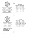
- Microwave energy propagates in waveguide only in particular modes (Fig. 1).
- rectangular waveguide used for transmission paths in most radar systems, the energy propagates in the dominant TE 10 (transverse electric wave).
- this energy must first be converted to a circularly symmetric mode and waveguide (circular tube or coaxial line).
- a circularly symmetric mode implies that the orientation of the E (electric) and H (magnetic) field patterns in the waveguide make the modes independent of rotation.
- a break between rotating and stationary parts of the rotary joint can be made with a small gap RF choke providing electrical continuity at the break.
- a conversion back to the TE 10 mode in rectangular waveguide is needed.
- Those persons skilled in the art desiring more information about a rotary joint with a small gap RF choke are referred to "Radiation Laboratory Series #9 - Microwave Transmission Circuits", George L. Ragan, pp. 193-199.
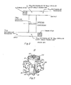
- rotary Joints have used a right angle transition from the TE 10 mode in rectangular waveguide to the TM 01 mode in circular waveguide.
- a circular hole has been cut in the broad wall of the rectangular waveguide the same diameter as the desired circular waveguide and the two waveguides are attached.
- the size of the circular waveguide is chosen to propagate the TM mode at the design frequency but small enough to 01 be in the non-prooagating region of any higher order modes.
- Shorting stubs are inserted in the open ends of the rectangular waveguides.
- millimeter wave rotary joint The same fabrication techniques and design principles used at lower frequencies can not be used to build an inexpensive millimeter wave rotary joint. Most millimeter wave components are made out of expensive coin-silver or plated materials which are necessary to keep losses low at these high frequencies. Intricate components can be made using electro-forming, casting, or other similar techniques, but all are expensive processes and some final machining operations would still be necessary for rotary joint parts.
- Another object of the invention is to provide a rotary joint which is capable of operation at substantially all microwave frequencies.
- a further object of the invention is to provide a compact, easy to manufacture rotary joint having low production costs.
- the rotary joint of this invention includes converting the TE mode in rectangular waveguide to the TE mode in a stationary circular waveguide, converting the TE mode to the TM mode in a 11 01 rotating circular waveguide and converting the TM back to the TE 10 mode in a rectangular waveguide.
- Figures la and 1b show the rectangular and circular waveguide modes (TE 10 , TE 11 and TM ) used in rotary joints. These modes are those referred to throughout the Following description.
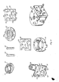
- the rotary joint 10 (Fig. 3) comprises an outer bearing housing 12 in which is mounted ball bearing races 14 and 16 (Fig. 4).
- An inner housing 18 (Fig.s 3 & 4) has an inner bearing housing portion 20 (Fig. 4) which coacts with the outer bearing housing and bearing retaining member 22 attached to the outer end of the inner bearing housing and bearing retaining member 24 attached to the outer end of outer bearing housing 12 to retain the bearing races 14 and 16 between the outer bearing housing 12 and inner housing portion 20 of inner housing 18.
- An electrical outer housing 26 is rigidly attached to the bearing outer housing 12.
- Transition irises 28 and 30 (Fig.s 3 & 4) are connected, respectively, to outer ends of the inner housing 18 and outer housing 26 to complete the rotary joint.
- the outer ends of the inner and outer housings and transition irises are configured to match rectangular waveguide sections.
- the transition irises 28 and 30 are identical in construction; therefore, only one need be described.
- the transition irises include a 0.700 inch square aluminum plate 32 having a 0.038 inch thickness, four 0.116 inch diameter holes 34 and four 0.067 inch diameter holes 36, 38, 40 and 42 for accommodating mechanical connector means hereinafter described.
- the iris 44 consists of an 0.082 inch diameter center hole and two 0.052 inch diameter holes having centers positioned 0.031 inches horizontally left and right of the center point of the center hole to form the iris shaped as shown in Figure 4.
- the inner housing 18, which is preferably an aluminum housing, (Fig. 4) has a square flange block 46 which corresponds to the transition iris 28 in that it has four 0.116 inch diameter holes 48 which are threaded to receive rectangular waveguide connecting bolts and four 0.067 inch holes 36'. 38', 40' and 42'. Holes 38' and 42' contain connecting dowels 50 and 52 and holes 36' and 40' are adapted to receive corresponding dowels of the rectangular waveguide (not shown).
- a 0.116 inch diameter center hole 54 forms the entrance to TE circular 11 waveguide section 56.
- the circular waveguide section 56 (Fig. 5) includes a tubular portion 58 forming a 0.116 inch diameter horizontally disposed passage 60 and a tubular portion 62 forming a corresponding vertically (90 degrees) disposed circular passage 64.
- the passages 60 and 64 intersect.
- Circular tuning stubs 66 and 68 having flat ends are provided adjacent the intersection of the passages 60 and 64 and are properly adjusted for RF tuning.
- the outer surface tubular portion 62 is recessed to form a seat for the roller bearing races 14 and 16 (Fig. 4).
- the electrical outer housing 26 (Fig.s 4 & 5) is preferably an aluminum, truncated circular block 70.
- the flat or truncated surface is integral with a square transition iris supporting block 72.
- Block 72 has a portion depending from the circular block 70.
- Block 70 has a horizontal 0.116 inch diameter circular passage 74 intersecting at right angles a vertical 0.116 inch diameter circular passage 76.
- Circular, flat ended tuning stubs 78 and 80 are selectively positioned, respectively, in passages 74 and 76 adjacent to the intersection for RF tuning of the energy passing through in the TM mode.
- Passage 76 terminates in a choke 82 01 formed in block 70 in a position corresponding to the end of passage 64 of the inner housing 18.
- Passage 74 terminates at the iris of transition iris 30.
- the dominant TE 11 mode in circular waveguide is analogous to the TE mode in rectangular waveguide and 10 that a right angle transition between two circular waveguides would convert the TE mode into the TM 01 mode.
- An abrupt junction has about a 2:1 VSWR, although the TE mode is excited.
- To improve the VSWR a quarter wavelength thick matching iris is provided at both ends of the rotary joint for efficient modal transitions.
- the iris is an improvement over known irises as it combines small size with the easy to build features necessary at millimeter wavelengths.
- the first circular waveguide is inline with the rectangular waveguide and converts the TE 10 mode in the rectangular waveguide to the TE mode in the first circular waveguide.
- the right angle transition to the second circular waveguide converts the TE mode of the 11 first circular waveguide to the TM mode in the second 01 circular waveguide, and the second iris converts the TE mode to the TE 10 mode for the rectangular waveguide.
- the duplex bearing pair is mounted outside the rotary joint. This physically limits the rotary joint to a scan angle of 140 degrees.
- the RF choke between rotating and stationary parts is a groove shaped and dimensioned as to impede the passage of guided waves with the 94 GHz range.
- the tuning stubs are flattened circular plugs with radial chokes to minimize contact loss and RF leakage.
- the insertion loss of the rotary joint is very sensitive to the tuning stub positions, and the best case VSWR positions do not coincide exactly with the positions for minimum insertion loss.
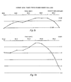
- the VSWR was tuned to less than 1.2 over a 2 GHz bandwidth (2%) (Fig.s 6a and 6b). At this VSWR the insertion loss was not minimal.
- the tuning stubs were moved slightly to get minimum insertion loss with some degradation in VSWR.
- the rotary joint is constructed of aluminum with an interior coating of a chromate conversion coating (such as Allodine 1500 sold by Amchem Products Incorporated) rather than coin-silver waveguide because the difference in insertion loss is minimal. Operation over a 1.5% bandwidth should be achievable with less than 0.5 dB insertion loss across the band.
- a chromate conversion coating such as Allodine 1500 sold by Amchem Products Incorporated
- the tuning stubs can be threaded to enable tuning with a screwdriver.
Landscapes
- Waveguide Connection Structure (AREA)
- Waveguide Aerials (AREA)
Abstract
Description
- This invention relates to radars and more particularly to a rotary joint applicable for all frequencies and to millimeter wavelengths, in particuiar.
- Rotary joints provide a continuous microwave transmission path between rotating and stationary sections of a mechanically scanned antenna system. They must operate over the scan range of the radar system with minimum distortion of the microwave signal. To do this, the voltage standing wave ratio (VSWR) (reflection) and insertion loss of a rotary joint needs to be minimized and have minimal variation with rotation over the desired frequency band.
- Microwave energy propagates in waveguide only in particular modes (Fig. 1). In rectangular waveguide, used for transmission paths in most radar systems, the energy propagates in the dominant TE10 (transverse electric wave). For rotary joints, this energy must first be converted to a circularly symmetric mode and waveguide (circular tube or coaxial line). A circularly symmetric mode implies that the orientation of the E (electric) and H (magnetic) field patterns in the waveguide make the modes independent of rotation. In the circular tube, a break between rotating and stationary parts of the rotary joint can be made with a small gap RF choke providing electrical continuity at the break. At the output of the rotary joint a conversion back to the TE10 mode in rectangular waveguide is needed. Those persons skilled in the art desiring more information about a rotary joint with a small gap RF choke are referred to "Radiation Laboratory Series #9 - Microwave Transmission Circuits", George L. Ragan, pp. 193-199.
- In the past (Fig. 2), rotary Joints have used a right angle transition from the TE10 mode in rectangular waveguide to the TM 01 mode in circular waveguide. A circular hole has been cut in the broad wall of the rectangular waveguide the same diameter as the desired circular waveguide and the two waveguides are attached. The size of the circular waveguide is chosen to propagate the TM mode at the design frequency but small enough to 01 be in the non-prooagating region of any higher order modes. Shorting stubs are inserted in the open ends of the rectangular waveguides.
- The shape and position of these stub "tunes" the rotary joint to operate in the desired Frequency band. The higher the frequency the smaller the parts become. For example, rectangular waveguide used in the 12-18 GHz range has a width of 0.622 inches wide compared to 0.100 inches for waveguide used at 94 GHz. Surface finish inside the waveguide becomes more critical at higher frequencies since the wavelength of the energy becomes proportionally smaller. The rectangular to circular waveguide rignt angle transition would be difficult and expensive to build at millimeter wavelengths.
- The same fabrication techniques and design principles used at lower frequencies can not be used to build an inexpensive millimeter wave rotary joint. Most millimeter wave components are made out of expensive coin-silver or plated materials which are necessary to keep losses low at these high frequencies. Intricate components can be made using electro-forming, casting, or other similar techniques, but all are expensive processes and some final machining operations would still be necessary for rotary joint parts.
- In addition to the mechanically scanned antenna, conical scan or twist reflector type antenna systems have been
- studied for radar systems operating at millimeter wave frequencies (above 40 GHz). These systems are less efficient in performance and are more costly.
- Accordingly it is an object of this invention to provide an efficient, high performance and low cost rotary joint for a mechanically scanned millimeter wavelength radar system.
- Another object of the invention is to provide a rotary joint which is capable of operation at substantially all microwave frequencies.
- A further object of the invention is to provide a compact, easy to manufacture rotary joint having low production costs.
- Briefly stated the rotary joint of this invention includes converting the TE mode in rectangular waveguide to the TE mode in a stationary circular waveguide, converting the TE mode to the TM mode in a 11 01 rotating circular waveguide and converting the TM back to the TE 10 mode in a rectangular waveguide.
- Other objects and features of the invention will become more readily apparent from the following detailed description when read in conjunction with the accompanying drawings in which:
- Figure la and lb are views showing the rectangular and circular waveguide modes used in rotary joints;
- Figure 2 is a view of a prior art rotary joint for a mechanically scanned radar system;
- Figure 3 is an isometric view of the rotary joint of the present invention;
- Figure 4 is an exploded view of the rotary joint of Fiaure 3:
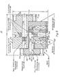
- Figure 5 is a cross-sectional view taken along line A-A of Figure 3;
- Figures 6a-6b are charts showing, respectively, the VSWR ano insertion loss when the rotary joint is tuned for best VSWR; and
- Figures 7a-7b are charts showing, respectively, the insertion loss and VSWR when the rotary joint is tuned for minimum insertion loss.
- Referring now to the drawings, Figures la and 1b show the rectangular and circular waveguide modes (TE10, TE11 and TM ) used in rotary joints. These modes are those referred to throughout the Following description.
- Referring now to Figures 3 and 4, the rotary joint 10 (Fig. 3) comprises an outer bearing
housing 12 in which is mounted ball bearingraces 14 and 16 (Fig. 4). An inner housing 18 (Fig.s 3 & 4) has an inner bearing housing portion 20 (Fig. 4) which coacts with the outer bearing housing and bearing retainingmember 22 attached to the outer end of the inner bearing housing and bearing retainingmember 24 attached to the outer end of outer bearinghousing 12 to retain thebearing races housing 12 andinner housing portion 20 ofinner housing 18. An electricalouter housing 26 is rigidly attached to the bearingouter housing 12.Transition irises 28 and 30 (Fig.s 3 & 4) are connected, respectively, to outer ends of theinner housing 18 andouter housing 26 to complete the rotary joint. The outer ends of the inner and outer housings and transition irises are configured to match rectangular waveguide sections. - By way of example only and not for purposes of limitation a 94 GHz rotary joint will now be described. The
transition irises 28 and 30 (Fig. 4) are identical in construction; therefore, only one need be described. The transition irises include a 0.700 inchsquare aluminum plate 32 having a 0.038 inch thickness, four 0.116inch diameter holes 34 and four 0.067inch diameter holes iris 44 consists of an 0.082 inch diameter center hole and two 0.052 inch diameter holes having centers positioned 0.031 inches horizontally left and right of the center point of the center hole to form the iris shaped as shown in Figure 4. - The
inner housing 18, which is preferably an aluminum housing, (Fig. 4) has asquare flange block 46 which corresponds to thetransition iris 28 in that it has four 0.116inch diameter holes 48 which are threaded to receive rectangular waveguide connecting bolts and four 0.067inch holes 36'. 38', 40' and 42'. Holes 38' and 42' contain connectingdowels diameter center hole 54 forms the entrance to TE circular 11waveguide section 56. - The circular waveguide section 56 (Fig. 5) includes a
tubular portion 58 forming a 0.116 inch diameter horizontally disposedpassage 60 and atubular portion 62 forming a corresponding vertically (90 degrees) disposedcircular passage 64. Thepassages Circular tuning stubs 66 and 68 having flat ends are provided adjacent the intersection of thepassages tubular portion 62 is recessed to form a seat for the roller bearingraces 14 and 16 (Fig. 4). - The electrical outer housing 26 (Fig.s 4 & 5) is preferably an aluminum, truncated
circular block 70. The flat or truncated surface is integral with a square transition iris supporting block 72. Block 72 has a portion depending from thecircular block 70.Block 70 has a horizontal 0.116 inch diametercircular passage 74 intersecting at right angles a vertical 0.116 inch diameter circular passage 76. Circular, flat endedtuning stubs passages 74 and 76 adjacent to the intersection for RF tuning of the energy passing through in the TM mode. Passage 76 terminates in achoke 82 01 formed inblock 70 in a position corresponding to the end ofpassage 64 of theinner housing 18.Passage 74 terminates at the iris oftransition iris 30. - In a study of the modal field patterns it was determined that the dominant TE11 mode in circular waveguide is analogous to the TE mode in rectangular waveguide and 10 that a right angle transition between two circular waveguides would convert the TE mode into the TM01 mode. To convert the TE10 mode of rectangular waveguide to the TE mode of circular waveguide an inline junction of the two waveguides is needed. An abrupt junction has about a 2:1 VSWR, although the TE mode is excited. To improve the VSWR, a quarter wavelength thick matching iris is provided at both ends of the rotary joint for efficient modal transitions. The iris is an improvement over known irises as it combines small size with the easy to build features necessary at millimeter wavelengths. The first circular waveguide is inline with the rectangular waveguide and converts the TE10 mode in the rectangular waveguide to the TE mode in the first circular waveguide. The right angle transition to the second circular waveguide converts the TE mode of the 11 first circular waveguide to the TM mode in the second 01 circular waveguide, and the second iris converts the TE mode to the TE10 mode for the rectangular waveguide.
- To keep the TM 01 circular waveguide section in scale with other rotary joint designs, the duplex bearing pair is mounted outside the rotary joint. This physically limits the rotary joint to a scan angle of 140 degrees. The RF choke between rotating and stationary parts is a groove shaped and dimensioned as to impede the passage of guided waves with the 94 GHz range. The tuning stubs are flattened circular plugs with radial chokes to minimize contact loss and RF leakage.
- The insertion loss of the rotary joint is very sensitive to the tuning stub positions, and the best case VSWR positions do not coincide exactly with the positions for minimum insertion loss. The VSWR was tuned to less than 1.2 over a 2 GHz bandwidth (2%) (Fig.s 6a and 6b). At this VSWR the insertion loss was not minimal. Thus, to obtain minimum insertion loss (Fig.s 7a & 7b) the tuning stubs were moved slightly to get minimum insertion loss with some degradation in VSWR.
- The rotary joint is constructed of aluminum with an interior coating of a chromate conversion coating (such as Allodine 1500 sold by Amchem Products Incorporated) rather than coin-silver waveguide because the difference in insertion loss is minimal. Operation over a 1.5% bandwidth should be achievable with less than 0.5 dB insertion loss across the band.
- Further it should be possible to achieve 360 degrees rotation by increasing the length of the TM01 circular waveguide section to provide bearing clearance. Also, with the circular waveguide passages open at the ends, the tuning stubs can be threaded to enable tuning with a screwdriver.
- Although several embodiments of this invention have been described, it will be apparent to a person skilled in the art that various modifications to the details of construction shown and described may be made without departing from the scope of this invention.
Claims (10)
Applications Claiming Priority (2)
| Application Number | Priority Date | Filing Date | Title |
|---|---|---|---|
| US06/761,718 US4654613A (en) | 1985-08-02 | 1985-08-02 | Radar rotary joint |
| US761718 | 1985-08-02 |
Publications (3)
| Publication Number | Publication Date |
|---|---|
| EP0210543A2 true EP0210543A2 (en) | 1987-02-04 |
| EP0210543A3 EP0210543A3 (en) | 1988-08-17 |
| EP0210543B1 EP0210543B1 (en) | 1994-03-02 |
Family
ID=25063066
Family Applications (1)
| Application Number | Title | Priority Date | Filing Date |
|---|---|---|---|
| EP86109759A Expired - Lifetime EP0210543B1 (en) | 1985-08-02 | 1986-07-16 | Radar rotary joint |
Country Status (3)
| Country | Link |
|---|---|
| US (1) | US4654613A (en) |
| EP (1) | EP0210543B1 (en) |
| DE (2) | DE210543T1 (en) |
Families Citing this family (7)
| Publication number | Priority date | Publication date | Assignee | Title |
|---|---|---|---|---|
| GB8812091D0 (en) * | 1988-05-21 | 1988-06-22 | Gen Electric Co Plc | Waveguide apparatus |
| US6927654B2 (en) * | 2003-02-26 | 2005-08-09 | Raytheon Company | Corrosion resistant waveguide system and method |
| KR100597207B1 (en) * | 2004-04-20 | 2006-07-06 | 주식회사 액티패스 | Waveguide rotary joint structure using a Circular waveguide transformer |
| US7446623B2 (en) * | 2005-07-14 | 2008-11-04 | X-Ether, Inc. | Mode transducer structure |
| JP5446552B2 (en) * | 2009-07-30 | 2014-03-19 | ソニー株式会社 | Wireless communication device, rotating structure, electronic device |
| IT1401404B1 (en) | 2010-08-03 | 2013-07-26 | G E M Elettronica S R L | ROTARY MICROWAVE POWER COUPLING WORKING ON TWO DISTINCT BANDS. |
| EP2796902B1 (en) * | 2013-04-23 | 2017-06-14 | Spinner GmbH | Millimeter Wave Scanning Imaging System |
Citations (4)
| Publication number | Priority date | Publication date | Assignee | Title |
|---|---|---|---|---|
| FR950269A (en) * | 1942-08-14 | 1949-09-22 | Emi Ltd | Guides for electro-magnetic waves |
| US2709242A (en) * | 1950-04-25 | 1955-05-24 | Raytheon Mfg Co | Wave guide structures |
| DE1032801B (en) * | 1956-02-01 | 1958-06-26 | Cie Generale D Electricite Soc | Device for conducting electromagnetic waves of the TE type through a waveguide with a circular cross-section with two straight sections, the axes of which form a certain angle between them |
| GB1080596A (en) * | 1963-08-23 | 1967-08-23 | Ass Elect Ind | Improvements relating to waveguide couplers |
Family Cites Families (3)
| Publication number | Priority date | Publication date | Assignee | Title |
|---|---|---|---|---|
| US2632806A (en) * | 1945-09-18 | 1953-03-24 | William M Preston | Mode filter |
| DE1071168B (en) * | 1957-08-29 | |||
| US3715688A (en) * | 1970-09-04 | 1973-02-06 | Rca Corp | Tm01 mode exciter and a multimode exciter using same |
-
1985
- 1985-08-02 US US06/761,718 patent/US4654613A/en not_active Expired - Lifetime
-
1986
- 1986-07-16 DE DE198686109759T patent/DE210543T1/en active Pending
- 1986-07-16 DE DE3689676T patent/DE3689676T2/en not_active Expired - Fee Related
- 1986-07-16 EP EP86109759A patent/EP0210543B1/en not_active Expired - Lifetime
Patent Citations (4)
| Publication number | Priority date | Publication date | Assignee | Title |
|---|---|---|---|---|
| FR950269A (en) * | 1942-08-14 | 1949-09-22 | Emi Ltd | Guides for electro-magnetic waves |
| US2709242A (en) * | 1950-04-25 | 1955-05-24 | Raytheon Mfg Co | Wave guide structures |
| DE1032801B (en) * | 1956-02-01 | 1958-06-26 | Cie Generale D Electricite Soc | Device for conducting electromagnetic waves of the TE type through a waveguide with a circular cross-section with two straight sections, the axes of which form a certain angle between them |
| GB1080596A (en) * | 1963-08-23 | 1967-08-23 | Ass Elect Ind | Improvements relating to waveguide couplers |
Non-Patent Citations (2)
| Title |
|---|
| G.L. RAGAN: "Microwave transmission circuits", 1st edition, vol. 9, 1948, pages 118-131,364-369, McGraw-Hill Book Co, Inc., New York, US * |
| IEEE TRANSACTIONS ON MICROWAVE THEORY AND TECHNIQUES, vol. MTT-18, no. 9, September 1970, pages 654-656; D.G. DE MESQUITA et al.: "A symmetrically excited microwave rotary joint" * |
Also Published As
| Publication number | Publication date |
|---|---|
| DE3689676T2 (en) | 1994-07-14 |
| US4654613A (en) | 1987-03-31 |
| DE3689676D1 (en) | 1994-04-07 |
| EP0210543B1 (en) | 1994-03-02 |
| DE210543T1 (en) | 1987-06-11 |
| EP0210543A3 (en) | 1988-08-17 |
Similar Documents
| Publication | Publication Date | Title |
|---|---|---|
| US9960495B1 (en) | Integrated single-piece antenna feed and circular polarizer | |
| US5517203A (en) | Dielectric resonator filter with coupling ring and antenna system formed therefrom | |
| US8013687B2 (en) | Ortho-mode transducer with TEM probe for coaxial waveguide | |
| US7064726B2 (en) | Antenna device and transmitting/receiving device | |
| EP1014470B1 (en) | Line transition device between dielectric waveguide and waveguide, and oscillator and transmitter using the same | |
| US4301347A (en) | Feed system for microwave oven | |
| US5083102A (en) | Dual mode dielectric resonator filters without iris | |
| EP1732158A1 (en) | Microwave filter including an end-wall coupled coaxial resonator | |
| US7821356B2 (en) | Ortho-mode transducer for coaxial waveguide | |
| JPH0677723A (en) | Continuous traverse stub element device and its manufacture | |
| EP0993064B1 (en) | Dual sidewall coupled orthomode transducer | |
| EP0657954B1 (en) | Improved multi-cavity dielectric filter | |
| US4868575A (en) | Phase slope equalizer for satellite antennas | |
| US4199764A (en) | Dual band combiner for horn antenna | |
| US4654613A (en) | Radar rotary joint | |
| US4298850A (en) | Double ridge waveguide rotary joint | |
| JP3303757B2 (en) | Non-radiative dielectric line component and integrated circuit thereof | |
| JP3279242B2 (en) | Different type non-radiative dielectric line converter structure and device | |
| US4754241A (en) | 3dB directional coupler | |
| JP3498611B2 (en) | Directional coupler, antenna device, and transmission / reception device | |
| US4890117A (en) | Antenna and waveguide mode converter | |
| US4039975A (en) | E plane folded hybrid with coaxial difference port | |
| US5463358A (en) | Multiple channel microwave rotary polarizer | |
| KR100471049B1 (en) | non-radiative dielectric waveguide mixer using a ring hybrid coupler | |
| US5801606A (en) | Pseudo-elliptical filter for the millimeter band using waveguide technology |
Legal Events
| Date | Code | Title | Description |
|---|---|---|---|
| PUAI | Public reference made under article 153(3) epc to a published international application that has entered the european phase |
Free format text: ORIGINAL CODE: 0009012 |
|
| AK | Designated contracting states |
Kind code of ref document: A2 Designated state(s): DE GB IT SE |
|
| ITCL | It: translation for ep claims filed |
Representative=s name: BARZANO' E ZANARDO ROMA S.P.A. |
|
| DET | De: translation of patent claims | ||
| PUAL | Search report despatched |
Free format text: ORIGINAL CODE: 0009013 |
|
| AK | Designated contracting states |
Kind code of ref document: A3 Designated state(s): DE GB IT SE |
|
| 17P | Request for examination filed |
Effective date: 19890126 |
|
| 17Q | First examination report despatched |
Effective date: 19911108 |
|
| GRAA | (expected) grant |
Free format text: ORIGINAL CODE: 0009210 |
|
| ITF | It: translation for a ep patent filed |
Owner name: BARZANO' E ZANARDO ROMA S.P.A. |
|
| AK | Designated contracting states |
Kind code of ref document: B1 Designated state(s): DE GB IT SE |
|
| REF | Corresponds to: |
Ref document number: 3689676 Country of ref document: DE Date of ref document: 19940407 |
|
| ITTA | It: last paid annual fee | ||
| PLBE | No opposition filed within time limit |
Free format text: ORIGINAL CODE: 0009261 |
|
| STAA | Information on the status of an ep patent application or granted ep patent |
Free format text: STATUS: NO OPPOSITION FILED WITHIN TIME LIMIT |
|
| EAL | Se: european patent in force in sweden |
Ref document number: 86109759.0 |
|
| 26N | No opposition filed | ||
| REG | Reference to a national code |
Ref country code: GB Ref legal event code: 732E |
|
| REG | Reference to a national code |
Ref country code: GB Ref legal event code: 732E |
|
| PGFP | Annual fee paid to national office [announced via postgrant information from national office to epo] |
Ref country code: GB Payment date: 19990722 Year of fee payment: 14 |
|
| PGFP | Annual fee paid to national office [announced via postgrant information from national office to epo] |
Ref country code: SE Payment date: 19990726 Year of fee payment: 14 |
|
| PGFP | Annual fee paid to national office [announced via postgrant information from national office to epo] |
Ref country code: DE Payment date: 19990928 Year of fee payment: 14 |
|
| PG25 | Lapsed in a contracting state [announced via postgrant information from national office to epo] |
Ref country code: GB Free format text: LAPSE BECAUSE OF NON-PAYMENT OF DUE FEES Effective date: 20000716 |
|
| PG25 | Lapsed in a contracting state [announced via postgrant information from national office to epo] |
Ref country code: SE Free format text: LAPSE BECAUSE OF NON-PAYMENT OF DUE FEES Effective date: 20000717 |
|
| GBPC | Gb: european patent ceased through non-payment of renewal fee |
Effective date: 20000716 |
|
| EUG | Se: european patent has lapsed |
Ref document number: 86109759.0 |
|
| PG25 | Lapsed in a contracting state [announced via postgrant information from national office to epo] |
Ref country code: DE Free format text: LAPSE BECAUSE OF NON-PAYMENT OF DUE FEES Effective date: 20010501 |
|
| PG25 | Lapsed in a contracting state [announced via postgrant information from national office to epo] |
Ref country code: IT Free format text: LAPSE BECAUSE OF NON-PAYMENT OF DUE FEES;WARNING: LAPSES OF ITALIAN PATENTS WITH EFFECTIVE DATE BEFORE 2007 MAY HAVE OCCURRED AT ANY TIME BEFORE 2007. THE CORRECT EFFECTIVE DATE MAY BE DIFFERENT FROM THE ONE RECORDED. Effective date: 20050716 |