EP0206975A2 - High consistency pressure screen and method of separating accepts and rejects - Google Patents
High consistency pressure screen and method of separating accepts and rejects Download PDFInfo
- Publication number
- EP0206975A2 EP0206975A2 EP86630103A EP86630103A EP0206975A2 EP 0206975 A2 EP0206975 A2 EP 0206975A2 EP 86630103 A EP86630103 A EP 86630103A EP 86630103 A EP86630103 A EP 86630103A EP 0206975 A2 EP0206975 A2 EP 0206975A2
- Authority
- EP
- European Patent Office
- Prior art keywords
- screen
- rotor
- accepts
- rejects
- outlet
- Prior art date
- Legal status (The legal status is an assumption and is not a legal conclusion. Google has not performed a legal analysis and makes no representation as to the accuracy of the status listed.)
- Granted
Links
Images

Classifications
-
- D—TEXTILES; PAPER
- D21—PAPER-MAKING; PRODUCTION OF CELLULOSE
- D21C—PRODUCTION OF CELLULOSE BY REMOVING NON-CELLULOSE SUBSTANCES FROM CELLULOSE-CONTAINING MATERIALS; REGENERATION OF PULPING LIQUORS; APPARATUS THEREFOR
- D21C9/00—After-treatment of cellulose pulp, e.g. of wood pulp, or cotton linters ; Treatment of dilute or dewatered pulp or process improvement taking place after obtaining the raw cellulosic material and not provided for elsewhere
- D21C9/02—Washing ; Displacing cooking or pulp-treating liquors contained in the pulp by fluids, e.g. wash water or other pulp-treating agents
- D21C9/06—Washing ; Displacing cooking or pulp-treating liquors contained in the pulp by fluids, e.g. wash water or other pulp-treating agents in filters ; Washing of concentrated pulp, e.g. pulp mats, on filtering surfaces
-
- D—TEXTILES; PAPER
- D21—PAPER-MAKING; PRODUCTION OF CELLULOSE
- D21D—TREATMENT OF THE MATERIALS BEFORE PASSING TO THE PAPER-MAKING MACHINE
- D21D5/00—Purification of the pulp suspension by mechanical means; Apparatus therefor
- D21D5/02—Straining or screening the pulp
- D21D5/023—Stationary screen-drums
- D21D5/026—Stationary screen-drums with rotating cleaning foils
Definitions
- the present invention relates to a method for separating accepts and rejects from a slurry of paper stock and to a high consistency pressure screen for carrying out the method.
- Clark-Pounder discloses a screening device which utilizes a screen or basket having a smooth interior surface spaced from a rotor which has dense and/or projections on its outer surface for producing localized changes in volume in the screening zone.
- Clarke-Pounder discloses a similar device in which the rejects are reduced by introducing dilution liquid into the material as it flows through the screening zone and across the screen.
- Joseph A. Bolton III and Peter E. LeBlanc in their United States Letters Patent 3 726 401 also disclose the use of a rotor having spaced projections in the form of bumps for creating a pulsation during screening, namely alternate positive screening pulses and negative screen-cleaning pulses.
- the primary object of the present invention is to provide a method and apparatus for high consistency pressure screening having low reject rates and low power consumption with a minimum fiber classification.
- the above object is achieved, according to the present invention, by flowing a slurry of paper stock through a screening zone between a rotor and a screen and creating in the screening zone continuous cyclic positive and negative pulses each of which covers approximately 50% of a pulsation cycle.
- the pulsation cycle includes a very brief positive pulse, a somewhat longer negative pulse and, during 50% of the cycle, no pulse magnitude.
- Flowing slurry, now subjected to the 50-50 pulsation cycle is subjected to continuous volumetric changes in the screening zone. Screening is advantageously achieved by providing a profile screen and by further providing a rotor having a profiled surface.
- the profile surface of the rotor comprises a blunt leading surface facing in the direction of rotation of the rotor, followed by an arcuate surface which recedes from the screen and therefore increases the volume between the rotor and the screen.
- the rotor appears as a double or quadruple cam structure. In addition to creating continuous positive and negative pulses the cams create great turbulence of the stock along the screen.
- screening apparatus is generally illustrated at 10 as comprising a housing 12, a pair of end walls 14, 16 and an outer, generally cylindrical wall 18.
- a slurry of paper stock is pumped, under pressure, through an inlet conduit 20 and enters the housing through an opening 22 at one end and flows toward a rejects outlet 24 and an accepts outlet 26.
- a profile screen 28 mounted to the inner surface of the housing by a pair of rings 30 which, with the housing wall 18 and the screen 28, form an accepts chamber 32.
- a rotor 34 is mounted on a drive shaft 36 driven by a drive 38.
- the rotor 34 comprises a hollow cylinder 40 which is connected to a member 42 keyed to the shaft 36, as indicated at 44.
- the rotor 34 further comprises end plates 46 connecting an outer wall 48 to the hollow cylinder 40 and sealing the ends of the rotor with respect to the flow of slurry.
- the rotor 34 comprises a cam-like configuration including a pair of blunt leading edges 50 facing in the direction of rotation 52, respectively followed by arcuate sections 54.
- the arcuate sections 54 have the same radius of curvature with the respective centers of the radii diametrically offset with respect to the axis of rotation.
- "blunt" when used in reference to the rotor shall mean a surface so shaped as to be capable of capturing a certain volume of stock and accelerating it up to rotor speed.
- the leading edges 50 could be forwardly inclined with respect to the direction of rotation, or could be concave in shape.
- Figs. 3 and 4 two different profiled surfaces are illustrated for the screen, namely the profile 56 in Fig. 3 and the profile 58 in Fig. 4. Normally, the profile is only provided on the inner surface of the screen, and other profiles than those shown could also be used.
- milk carton stock was pulped in a 1000 4 Tridyne with 1.5 % sodium hypochlorite for approximately 30 minutes.
- the stock was extracted through 3.18 mm(l/8") perforations in a pulper grate at 5.01% consistency. No debris was added to the stock; however, there were many small flakes and plastics in the pulp. In essence, this pulp was prescreened by the 3.18 mm (1/8") perforations in the pulper.
- Table 1 lists the data for the 1.98 mm (0.078") perforate screen. It should be noted that as flow increases the motor load decreases. This is caused primarily by a higher inlet stock velocity which decreases the relative rotor to stock velocities and requires less power. At the high flows, the power required was about 0.06 kW Day/Acc. Tonne, (0.08 HPD/Acc.Ton). A small change is noted in the consistencies at the 10% rejects rate and a larger change at the 5% rejects rate. The freeness change did not appear to be affected by the reject rate and is small although there is a change from the inlet to the accepts.
- Table 2 lists the data for the 1.38 mm (0.055") perforate screen.
- the power is essentially the same as above at less than 0.08 kW d/t(0.1 HPD/T) at high flows.
- the freeness change with this screen illustrates the accept CFS higher than the feed with the reject CFS lower than the feed. This is normal for smaller perforations, but the effects are magnified by the large plastics in the reject stream, which are sufficiently large to drop the freeness and sufficiently light to change the consistency.
- the debris removal for both screens is illustrated with respect to the percent rejects by weight.
- the 1.38 mm (0.055")screen provided better debris removal than the 1.98mm (0.078") screen.
- the debris removal was 52% for the 1.98 mm (0.078") screen and was 71% for the 1.38 mm (0.055") screen.
- the debris content was measured using an image analyzer. Four one gram view sheets were made from each pulp sample. The analyzer was set to count as larger a section as possible of the sheet, which amounted to about 80% of the sheet. Sensitivity was set such that the particles which were visible to the eye were counted . The magnification amounted to about 1.4X to achieve the visual to analyzer correlation. The results of these tests are tabulated below in Table 3 showing the debris area measured for each inlet, accept and reject sample. The debris removal is calculated from the equation :
- a positive pulse As mentioned previously herein, during one cycle approximately 50% of the cycle is a positive pulse, and 50% a negative pulse. This is substantially different from conventional screens which have periods of positive and negative pulse, but also substantial periods of zero pulse.
- the long duration negative pulse in the present invention creates a back flow or flushing through the screen plate. Because of the design of the profiled screens, it is much more difficult for the fibers to pass in the reverse direction than in the screening direction of the positive pulse. Additionally, on the outside of the screen basket, there is very little turbulence when compared to the turbulence generated on the inside of the screen cylinder by the blunt leading edge during the positive pulse. Therefore, during the period of negative pulse, the back flow from the accept side to the inlet side of the screen is primarily flow of water only.
- the stock on the accept side of the screen tends to form a mat on the accept side, and therefore there is merely a dewatering function.
- This theory has been substantiated by the test findings that the accepts' consistency is generally at least slightly higher than the inlet consistency, and the reject consistency is lower than the inlet consistency. Therefore, the accepts are dewatered to a certain extent, most likely during the negative pulse phase of each cycle. Test have also indicated that the smaller the perforations on the screen, the greater the dewatering phenomenon. This can be explained by the poor mat formation in the large perforation screens which allow accepts fiber to flow back with the water during the negative pulse.
- Yet another advantage achieved by the present invention is that the rotor can be operated at greater clearance from the screen than other blade or foil type screens. Junk or debris contained in the stock will not wedge between the rotor and screen, which can be a problem in other types of screens.
Landscapes
- Engineering & Computer Science (AREA)
- Mechanical Engineering (AREA)
- Life Sciences & Earth Sciences (AREA)
- Wood Science & Technology (AREA)
- Paper (AREA)
- Filtration Of Liquid (AREA)
- Combined Means For Separation Of Solids (AREA)
- Separation Of Solids By Using Liquids Or Pneumatic Power (AREA)
Abstract
Description
- The present invention relates to a method for separating accepts and rejects from a slurry of paper stock and to a high consistency pressure screen for carrying out the method.
- In his United States Letters Patent 3 363 759 I.J. Clark-Pounder discloses a screening device which utilizes a screen or basket having a smooth interior surface spaced from a rotor which has dense and/or projections on its outer surface for producing localized changes in volume in the screening zone. In his United States Letters Patent 3 437 204 Clarke-Pounder discloses a similar device in which the rejects are reduced by introducing dilution liquid into the material as it flows through the screening zone and across the screen.
- Joseph A. Bolton III and Peter E. LeBlanc, in their United States Letters Patent 3 726 401 also disclose the use of a rotor having spaced projections in the form of bumps for creating a pulsation during screening, namely alternate positive screening pulses and negative screen-cleaning pulses.
- Ahlstrom Machinery Inc. of Glens Falls, New York, produces "profile" screens for use in pressure screen devices.
- The primary object of the present invention is to provide a method and apparatus for high consistency pressure screening having low reject rates and low power consumption with a minimum fiber classification.
- The above object is achieved, according to the present invention, by flowing a slurry of paper stock through a screening zone between a rotor and a screen and creating in the screening zone continuous cyclic positive and negative pulses each of which covers approximately 50% of a pulsation cycle. Typically, in a conventional screen the pulsation cycle includes a very brief positive pulse, a somewhat longer negative pulse and, during 50% of the cycle, no pulse magnitude. Flowing slurry, now subjected to the 50-50 pulsation cycle is subjected to continuous volumetric changes in the screening zone. Screening is advantageously achieved by providing a profile screen and by further providing a rotor having a profiled surface. The profile surface of the rotor comprises a blunt leading surface facing in the direction of rotation of the rotor, followed by an arcuate surface which recedes from the screen and therefore increases the volume between the rotor and the screen. Advantageously , and as viewed from the end of the rotor, the rotor appears as a double or quadruple cam structure. In addition to creating continuous positive and negative pulses the cams create great turbulence of the stock along the screen.
- Other objects, features and advantages of the invention, its organization, construction and operation will be best understood from the following detailed description, taken in conjunction with the accompanying drawings, on which:
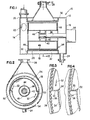
- Fig. 1 is a longitudinal sectional view of a pressure screen constructed in accordance with the present invention ;
- Fig. 2 is a sectional view taken substantially along the line II-II of Fig. 1;
- Fig. 3 is a fragmentary sectional view particularly illustrating the relationship between the inner surface of the profile screen and the profile surface of the rotor, utilizing a first type of profile screen;
- Fig. 4 is a fragmentary sectional view , similar to that of Fig. 3, showing the use of a second type of profile screen;
- Fig. 5 is a graphic representation of the pulsations measured in the pressure screen;
- Fig. 6 is a graphic illustration of the pressure drop verses the accept flow for a pressure screen constructed in accordance with the present invention; and
- Fig. 7 is a graphic illustration of the debris removal verses the percent of rejects by weight for a pressure screen constructed in accordance with the present invention.
- Referring to Figs. 1-4, screening apparatus is generally illustrated at 10 as comprising a
housing 12, a pair ofend walls cylindrical wall 18. A slurry of paper stock is pumped, under pressure, through aninlet conduit 20 and enters the housing through an opening 22 at one end and flows toward arejects outlet 24 and an acceptsoutlet 26. - Mounted within the housing and in the path of the aforementioned flow is a
profile screen 28 mounted to the inner surface of the housing by a pair ofrings 30 which, with thehousing wall 18 and thescreen 28, form anaccepts chamber 32. - A
rotor 34 is mounted on adrive shaft 36 driven by adrive 38. Therotor 34 comprises ahollow cylinder 40 which is connected to amember 42 keyed to theshaft 36, as indicated at 44. Therotor 34 further comprisesend plates 46 connecting anouter wall 48 to thehollow cylinder 40 and sealing the ends of the rotor with respect to the flow of slurry. - As best seen in Fig. 2, the
rotor 34 comprises a cam-like configuration including a pair of blunt leadingedges 50 facing in the direction ofrotation 52, respectively followed byarcuate sections 54. In a particular construction, thearcuate sections 54 have the same radius of curvature with the respective centers of the radii diametrically offset with respect to the axis of rotation. Although only two of such semicylindrical structures have been shown, a plurality may be provided for very large pressure screens. As used in the specification and claims hereof, "blunt" when used in reference to the rotor shall mean a surface so shaped as to be capable of capturing a certain volume of stock and accelerating it up to rotor speed. Thus, for example, the leadingedges 50 could be forwardly inclined with respect to the direction of rotation, or could be concave in shape. - Referring to Figs. 3 and 4, two different profiled surfaces are illustrated for the screen, namely the
profile 56 in Fig. 3 and theprofile 58 in Fig. 4. Normally, the profile is only provided on the inner surface of the screen, and other profiles than those shown could also be used. - After realizing the pulsation phenomenon set forth above, investigations were undertaken to determine the cause thereof, including the geometric causes, the dynamic causes and the stock causes. In the area of geometric causes the sharp positive pressure pulse, the area of negative and positive pressure pulses, the condition of the screen plate surface and the rotor-screen clearance were investigated. As dynamic causes, the surface speed of the rotor, the pulse frequency and the pressure drops over the screen were considered. The stock causes include consistency, temperature and type of fiber.
- Investigations were undertaken using milk carton stock at 4.5% consistency. A pump capacity of about 4542 1/min (1200 GPM) was attained utilizing a 1.98mm (0.078") perforate screen and a 1.38 mm (0.055") perforate screen with more than 272 tonnes/day processed using 18.64 kW (25 HP). It was determined that at 5.5% rejects by weight, a debris removal of 52% was attained using the 1.98mm (0.078") screen and a debris removal of 71% with the 1.38 mm (0.055") screen. The inlet to accept freeness dropped an average of 8 points for the 1.98 mm (0.078") screen and increased by 10 points on the 1.38 mm (0.055") screen. The screens were stable on all tests and can easily screen milk carton stock.
- In carrying out the aforementioned test, milk carton stock was pulped in a 1000 4 Tridyne with 1.5 % sodium hypochlorite for approximately 30 minutes. The stock was extracted through 3.18 mm(l/8") perforations in a pulper grate at 5.01% consistency. No debris was added to the stock; however, there were many small flakes and plastics in the pulp. In essence, this pulp was prescreened by the 3.18 mm (1/8") perforations in the pulper.
- With the rotor shown in Fig. 2,the 1.98 mm (0.078") screen and the 1.38 mm (0.055") screen were used and the rotor was run at a constant 750 RPM. The screen system was initially filled with water which diluted the pulp from 5% to 4.5% . A series of flows were selected so that a pressure drop verses flow curve could be generated. Reject flow was held to approximately 10% of the accepts for these tests. Samples of the inlet, accept and reject stock were taken at nominal mill production rates in one test and at pump capacity in a second test. In a third test, pump capacity was also utilized, but at a 5% rejects flow.
- The following schedules of table 1 and 2 show the data gathered during the aforementioned trials.

- Table 1 lists the data for the 1.98 mm (0.078") perforate screen. It should be noted that as flow increases the motor load decreases. This is caused primarily by a higher inlet stock velocity which decreases the relative rotor to stock velocities and requires less power. At the high flows, the power required was about 0.06 kW Day/Acc. Tonne, (0.08 HPD/Acc.Ton). A small change is noted in the consistencies at the 10% rejects rate and a larger change at the 5% rejects rate. The freeness change did not appear to be affected by the reject rate and is small although there is a change from the inlet to the accepts.

- Table 2 lists the data for the 1.38 mm (0.055") perforate screen. The power is essentially the same as above at less than 0.08 kW d/t(0.1 HPD/T) at high flows. The freeness change with this screen illustrates the accept CFS higher than the feed with the reject CFS lower than the feed. This is normal for smaller perforations, but the effects are magnified by the large plastics in the reject stream, which are sufficiently large to drop the freeness and sufficiently light to change the consistency.
- Referring to Fig. 6, the pressure drop verses the accept flow is illustrated for both screens. The upper limit on both screens was the pump capacity and not the screen. The 1.38 mm (0.055") curve is almost at the maximum while the 1.98 mm (0.078") curve shows that additional capacity is available.
- Referring to Fig. 7, the debris removal for both screens is illustrated with respect to the percent rejects by weight. As shown,the 1.38 mm (0.055")screen provided better debris removal than the 1.98mm (0.078") screen. At a reject rate of 5.5% rejects by weight, the debris removal was 52% for the 1.98 mm (0.078") screen and was 71% for the 1.38 mm (0.055") screen.
- The debris content was measured using an image analyzer. Four one gram view sheets were made from each pulp sample. The analyzer was set to count as larger a section as possible of the sheet, which amounted to about 80% of the sheet. Sensitivity was set such that the particles which were visible to the eye were counted . The magnification amounted to about 1.4X to achieve the visual to analyzer correlation. The results of these tests are tabulated below in Table 3 showing the debris area measured for each inlet, accept and reject sample. The debris removal is calculated from the equation :


- From these tests and observations, a theory has been developed on why the rotor and screen as described herein operate superiorly to other screen apparatus known in the art. Previous lobe screens, foil screens and the like have created positive pulses while moving through the stock without significantly introducing turbulent energy into the stock. There is minimal stock fluidization generated in these designs. The blunt
leading edges 50 in the present invention move through the stock, each capturing a certain volume of stock and accelerating it in the tangential direction of the rotor up to rotor speed. At this high velocity, stock moves past theprofile screen 28, as significant turbulence is generated along the cylinder surface, highly fluidizing the stock. This high fluidization prevents agglomeration, floccing or matting of the individual fibers in the stock, and enables the screen to function at much higher consistencies than conventional screens. When floccing or agglomeration occurs, the individual fibers cannot pass through the screen cylinder holes, and for this reason screening previously has been done at much lower consistencies. - As mentioned previously herein, during one cycle approximately 50% of the cycle is a positive pulse, and 50% a negative pulse. This is substantially different from conventional screens which have periods of positive and negative pulse, but also substantial periods of zero pulse. The long duration negative pulse in the present invention creates a back flow or flushing through the screen plate. Because of the design of the profiled screens, it is much more difficult for the fibers to pass in the reverse direction than in the screening direction of the positive pulse. Additionally, on the outside of the screen basket, there is very little turbulence when compared to the turbulence generated on the inside of the screen cylinder by the blunt leading edge during the positive pulse. Therefore, during the period of negative pulse, the back flow from the accept side to the inlet side of the screen is primarily flow of water only. The stock on the accept side of the screen tends to form a mat on the accept side, and therefore there is merely a dewatering function. This theory has been substantiated by the test findings that the accepts' consistency is generally at least slightly higher than the inlet consistency, and the reject consistency is lower than the inlet consistency. Therefore, the accepts are dewatered to a certain extent, most likely during the negative pulse phase of each cycle. Test have also indicated that the smaller the perforations on the screen, the greater the dewatering phenomenon. This can be explained by the poor mat formation in the large perforation screens which allow accepts fiber to flow back with the water during the negative pulse.
- Prior to the present invention, conventional screening was performed at about 2% consistency with some screens, though less efficient, operating at about 4% consistency. The present screen has operated at 4%, 5% and 6% consistency without any decline in the debris removal efficiency and without an increase in the reject rate. In all other known screens as consistency is increased, the debris removal efficiency is decreased and the reject rate increases. In the present screen, increasing consistency has not coincided with decreased efficiency and increased reject rate. This result can be explained in the present screen by the fact that the blunt leading edge of the rotor creates greater turbulence and fluidization of the stock thereby allowing stock to flow through the plate at high consistency. During the negative pulse phase, the back flush or dewatering dilutes the stock within the screen thereby eliminating the normal thickening of the screen zone stock and the rejects which occurs in other screens.
- Yet another advantage achieved by the present invention is that the rotor can be operated at greater clearance from the screen than other blade or foil type screens. Junk or debris contained in the stock will not wedge between the rotor and screen, which can be a problem in other types of screens.
- Although we have described the invention by reference to particular illustrative embodiments thereof and with reference to specific test results, many changes and modifications of the invention may become apparent to those skilled in the art without departing from the spirit and scope of the invention.We therefore intend to include within the patent warranted hereon all such changes and modifications as may reasonably and properly be included within the scope of our contribution to the art.
Claims (12)
said rotor comprising a profiled surface including means effective to cause turbulence of the slurry and to provide a stock and screen-cleaning pulsation cycle of approximately + 50% positive and -50% negative in the accepts direction of flow.
Applications Claiming Priority (2)
| Application Number | Priority Date | Filing Date | Title |
|---|---|---|---|
| US06/746,734 US4855038A (en) | 1985-06-20 | 1985-06-20 | High consistency pressure screen and method of separating accepts and rejects |
| US746734 | 1985-06-20 |
Publications (3)
| Publication Number | Publication Date |
|---|---|
| EP0206975A2 true EP0206975A2 (en) | 1986-12-30 |
| EP0206975A3 EP0206975A3 (en) | 1987-03-25 |
| EP0206975B1 EP0206975B1 (en) | 1990-04-18 |
Family
ID=25002109
Family Applications (1)
| Application Number | Title | Priority Date | Filing Date |
|---|---|---|---|
| EP86630103A Expired - Lifetime EP0206975B1 (en) | 1985-06-20 | 1986-06-12 | High consistency pressure screen and method of separating accepts and rejects |
Country Status (14)
| Country | Link |
|---|---|
| US (1) | US4855038A (en) |
| EP (1) | EP0206975B1 (en) |
| JP (1) | JPS61296193A (en) |
| KR (1) | KR900002099B1 (en) |
| CN (1) | CN1011146B (en) |
| BR (1) | BR8602828A (en) |
| CA (1) | CA1268141A (en) |
| DE (1) | DE3670518D1 (en) |
| ES (1) | ES8801400A1 (en) |
| FI (1) | FI85730C (en) |
| IN (1) | IN166375B (en) |
| MX (1) | MX162931B (en) |
| PH (1) | PH26032A (en) |
| PL (1) | PL155075B1 (en) |
Cited By (10)
| Publication number | Priority date | Publication date | Assignee | Title |
|---|---|---|---|---|
| EP0294832A2 (en) * | 1987-06-11 | 1988-12-14 | A. Ahlstrom Corporation | Pulp screening apparatus |
| EP0299258A1 (en) * | 1987-06-26 | 1989-01-18 | A. Ahlstrom Corporation | A high flow capacity barrier type screening apparatus and method therefor |
| EP0486209A1 (en) * | 1990-11-13 | 1992-05-20 | The Black Clawson Company | Screening apparatus for paper making stock |
| US5232552A (en) * | 1988-11-17 | 1993-08-03 | Sunds Defibrator Industries Aktiebolag | Screening device |
| WO1994000634A1 (en) * | 1992-06-20 | 1994-01-06 | Hermann Finckh Maschinenfabrik Gmbh & Co. | Pressure sorter for fibre suspensions |
| US5476178A (en) * | 1993-06-16 | 1995-12-19 | E & M Lamort | Rotor for pressurized hydrodynamic purification of paper pulp and equipment fitted with this rotor |
| US5524770A (en) * | 1989-10-23 | 1996-06-11 | Beloit Technologies, Inc. | Basket profile for screens |
| US5566833A (en) * | 1995-01-25 | 1996-10-22 | Hermannfinckh Maschinenfabrik Gmbh & Co. | Pressure sorter for fiber suspensions as well as a process for the preparation of fiber suspensions |
| US8297445B2 (en) | 2007-11-14 | 2012-10-30 | Filtration Fibrewall Inc. | Screen basket |
| US8469198B2 (en) | 2005-05-09 | 2013-06-25 | Kadant Canada Corp. | Screen basket with replaceable profiled bars |
Families Citing this family (19)
| Publication number | Priority date | Publication date | Assignee | Title |
|---|---|---|---|---|
| US4981583A (en) * | 1985-06-20 | 1991-01-01 | Beloit Corporation | High consistency pressure screen and method of separating accepts and rejects |
| US5110456A (en) * | 1985-06-20 | 1992-05-05 | Beloit Corporation | High consistency pressure screen and method of separating accepts and rejects |
| US5156750A (en) * | 1987-07-08 | 1992-10-20 | A. Ahlstrom Corporation | Method and apparatus for thickening a fiber suspension and removing fine particles therefrom |
| JPH089838B2 (en) * | 1987-07-08 | 1996-01-31 | エイ.アフルストロム コ−ポレ−ション | Method and device for thickening fiber suspensions |
| JPH0189991U (en) * | 1987-12-03 | 1989-06-13 | ||
| US4954249A (en) * | 1988-06-10 | 1990-09-04 | Beloit Corporation | Wave screen plate |
| US5172813A (en) * | 1989-05-17 | 1992-12-22 | A. Ahlstrom Corporation | Method and an apparatus for treating fiber suspension |
| DE3925020A1 (en) * | 1989-07-28 | 1991-01-31 | Voith Gmbh J M | SORTER |
| US5139154A (en) * | 1989-12-27 | 1992-08-18 | Beloit Corporation | Wear screen plate and method of manufacture thereof |
| US5041212A (en) * | 1990-01-02 | 1991-08-20 | Beloit Corporation | Efficiency screen plate for screening pulp |
| US5255540A (en) * | 1990-06-29 | 1993-10-26 | Beloit Technologies, Inc. | Pressurized dynamic washer |
| US5072834A (en) * | 1990-11-19 | 1991-12-17 | The Black Clawson Company | Screening apparatus for paper making stock |
| US5307939A (en) * | 1992-07-13 | 1994-05-03 | Ingersoll-Rand Company | Screening apparatus for papermaking pulp |
| KR100331594B1 (en) | 1993-02-11 | 2002-08-08 | 폴 블랑세 | Device for separating solids from fluid |
| US5538632A (en) * | 1993-10-28 | 1996-07-23 | Beloit Technologies, Inc. | Multiple filter dynamic washer |
| AUPM628594A0 (en) * | 1994-06-17 | 1994-07-07 | Blanche, Paul | An apparatus for the separation of solids from flowing liquid |
| US5791495A (en) * | 1996-03-11 | 1998-08-11 | Beloit Technologies, Inc. | Paper pulp screen cylinder |
| US7465391B2 (en) | 2005-09-09 | 2008-12-16 | Cds Technologies, Inc. | Apparatus for separating solids from flowing liquids |
| FI126709B (en) * | 2013-06-20 | 2017-04-13 | Valmet Technologies Inc | Drum element, sorter and method for sorting the pulp |
Citations (4)
| Publication number | Priority date | Publication date | Assignee | Title |
|---|---|---|---|---|
| US3400820A (en) * | 1965-03-30 | 1968-09-10 | Bird Machine Co | Screening apparatus with rotary pulsing member |
| US3680696A (en) * | 1970-03-23 | 1972-08-01 | Bird Machine Co | Screening |
| US3726401A (en) * | 1970-12-16 | 1973-04-10 | Bird Machine Co | Screening machine |
| FR2410081A1 (en) * | 1977-11-23 | 1979-06-22 | Lamort Ingenieurs Construc E E | APPARATUS FOR PULPING PAPER PULP |
Family Cites Families (9)
| Publication number | Priority date | Publication date | Assignee | Title |
|---|---|---|---|---|
| US1921750A (en) * | 1931-04-01 | 1933-08-08 | Carl Nebrich | Centrifugal separator for straining pulpy material, such as wood pulp, cellulose, paper pulp, and the like |
| US1974651A (en) * | 1933-03-17 | 1934-09-25 | Haug Anton Joseph | Pulp screening machine |
| US3363759A (en) * | 1964-04-29 | 1968-01-16 | Bird Machine Co | Screening apparatus with rotary pulsing member |
| US3437204A (en) * | 1965-12-27 | 1969-04-08 | Bird Machine Co | Screening apparatus |
| US3581893A (en) * | 1968-01-02 | 1971-06-01 | Improved Machinery Inc | Screening apparatus |
| US3814244A (en) * | 1972-05-30 | 1974-06-04 | Ingersoll Rand Canada | Apparatus for fractionating fluid suspensions |
| DD129814A1 (en) * | 1977-01-24 | 1978-02-08 | Werner Kretzschmar | PRESSURE REGULATOR WITH VERTICAL RUBBER FOR FIBROUS SUSPENSIONS |
| DE3109196A1 (en) * | 1981-03-11 | 1982-10-14 | O & K Orenstein & Koppel Ag, 1000 Berlin | CARGO FOR REFRIGERATION |
| US4462901A (en) * | 1981-12-28 | 1984-07-31 | Gauld W Thomas | Apparatus for screening fibrous stock |
-
1985
- 1985-06-20 US US06/746,734 patent/US4855038A/en not_active Expired - Lifetime
-
1986
- 1986-05-13 CN CN86103397A patent/CN1011146B/en not_active Expired
- 1986-06-09 CA CA000511132A patent/CA1268141A/en not_active Expired - Lifetime
- 1986-06-12 EP EP86630103A patent/EP0206975B1/en not_active Expired - Lifetime
- 1986-06-12 DE DE8686630103T patent/DE3670518D1/en not_active Expired - Lifetime
- 1986-06-13 MX MX2796A patent/MX162931B/en unknown
- 1986-06-16 IN IN445/CAL/86A patent/IN166375B/en unknown
- 1986-06-17 JP JP61141197A patent/JPS61296193A/en active Granted
- 1986-06-18 FI FI862592A patent/FI85730C/en not_active IP Right Cessation
- 1986-06-18 BR BR8602828A patent/BR8602828A/en not_active IP Right Cessation
- 1986-06-19 KR KR1019860004875A patent/KR900002099B1/en not_active IP Right Cessation
- 1986-06-19 ES ES556268A patent/ES8801400A1/en not_active Expired
- 1986-06-19 PH PH33908A patent/PH26032A/en unknown
- 1986-06-20 PL PL1986260187A patent/PL155075B1/en unknown
Patent Citations (4)
| Publication number | Priority date | Publication date | Assignee | Title |
|---|---|---|---|---|
| US3400820A (en) * | 1965-03-30 | 1968-09-10 | Bird Machine Co | Screening apparatus with rotary pulsing member |
| US3680696A (en) * | 1970-03-23 | 1972-08-01 | Bird Machine Co | Screening |
| US3726401A (en) * | 1970-12-16 | 1973-04-10 | Bird Machine Co | Screening machine |
| FR2410081A1 (en) * | 1977-11-23 | 1979-06-22 | Lamort Ingenieurs Construc E E | APPARATUS FOR PULPING PAPER PULP |
Cited By (12)
| Publication number | Priority date | Publication date | Assignee | Title |
|---|---|---|---|---|
| EP0294832A2 (en) * | 1987-06-11 | 1988-12-14 | A. Ahlstrom Corporation | Pulp screening apparatus |
| EP0294832A3 (en) * | 1987-06-11 | 1989-03-08 | A. Ahlstrom Corporation | Pulp screening apparatus |
| EP0299258A1 (en) * | 1987-06-26 | 1989-01-18 | A. Ahlstrom Corporation | A high flow capacity barrier type screening apparatus and method therefor |
| US5232552A (en) * | 1988-11-17 | 1993-08-03 | Sunds Defibrator Industries Aktiebolag | Screening device |
| US5524770A (en) * | 1989-10-23 | 1996-06-11 | Beloit Technologies, Inc. | Basket profile for screens |
| EP0486209A1 (en) * | 1990-11-13 | 1992-05-20 | The Black Clawson Company | Screening apparatus for paper making stock |
| WO1994000634A1 (en) * | 1992-06-20 | 1994-01-06 | Hermann Finckh Maschinenfabrik Gmbh & Co. | Pressure sorter for fibre suspensions |
| US5601192A (en) * | 1992-06-20 | 1997-02-11 | Hermann Finckh Maschinenfabrik Gmbh & Co. | Pressure sorter for fiber suspensions |
| US5476178A (en) * | 1993-06-16 | 1995-12-19 | E & M Lamort | Rotor for pressurized hydrodynamic purification of paper pulp and equipment fitted with this rotor |
| US5566833A (en) * | 1995-01-25 | 1996-10-22 | Hermannfinckh Maschinenfabrik Gmbh & Co. | Pressure sorter for fiber suspensions as well as a process for the preparation of fiber suspensions |
| US8469198B2 (en) | 2005-05-09 | 2013-06-25 | Kadant Canada Corp. | Screen basket with replaceable profiled bars |
| US8297445B2 (en) | 2007-11-14 | 2012-10-30 | Filtration Fibrewall Inc. | Screen basket |
Also Published As
| Publication number | Publication date |
|---|---|
| KR870000486A (en) | 1987-02-18 |
| PH26032A (en) | 1992-01-29 |
| FI85730C (en) | 1992-05-25 |
| JPH0133598B2 (en) | 1989-07-13 |
| JPS61296193A (en) | 1986-12-26 |
| EP0206975B1 (en) | 1990-04-18 |
| KR900002099B1 (en) | 1990-04-02 |
| US4855038A (en) | 1989-08-08 |
| BR8602828A (en) | 1987-02-10 |
| PL155075B1 (en) | 1991-10-31 |
| CN1011146B (en) | 1991-01-09 |
| FI862592A0 (en) | 1986-06-18 |
| FI85730B (en) | 1992-02-14 |
| CN86103397A (en) | 1986-12-17 |
| MX162931B (en) | 1991-07-15 |
| DE3670518D1 (en) | 1990-05-23 |
| ES8801400A1 (en) | 1988-01-01 |
| CA1268141A (en) | 1990-04-24 |
| EP0206975A3 (en) | 1987-03-25 |
| ES556268A0 (en) | 1988-01-01 |
| FI862592A (en) | 1986-12-21 |
| IN166375B (en) | 1990-04-21 |
Similar Documents
| Publication | Publication Date | Title |
|---|---|---|
| EP0206975B1 (en) | High consistency pressure screen and method of separating accepts and rejects | |
| US3726401A (en) | Screening machine | |
| US4356085A (en) | Rotary screening machine for pulp suspensions | |
| EP0637348B1 (en) | Apparatus for treating fiber suspension | |
| CA2154258C (en) | Screening apparatus for papermaking pulp | |
| US4919797A (en) | Screening apparatus for paper making stock | |
| US4699324A (en) | Combined screening and reject reduction | |
| US4396502A (en) | Screening apparatus for a papermaking machine | |
| CA1156975A (en) | Center flow screening apparatus | |
| US4981583A (en) | High consistency pressure screen and method of separating accepts and rejects | |
| EP0142054A2 (en) | Screening apparatus with light reject removal | |
| FI67580C (en) | FOERFARANDE OCH ANORDNING FOER FIBRERING SILNING OCH PUMPNING AV CELLULOSAMASSA OCH RETURPAPPER | |
| US5110456A (en) | High consistency pressure screen and method of separating accepts and rejects | |
| US8950584B2 (en) | Apparatus for screening fibrous suspensions | |
| EP0650542B1 (en) | Screening apparatus for papermaking pulp | |
| US4383918A (en) | High turbulence screen | |
| JPH05179593A (en) | Apparatus for treating fiber suspension liquid | |
| FI77481C (en) | Strainer. | |
| CA1128368A (en) | Method and apparatus for pumping fibre suspensions | |
| CN211713509U (en) | Pumping screen and pumping screening system | |
| US4111799A (en) | Stock screen foil | |
| CA1180686A (en) | Paper making stock screening apparatus incorporating circular apertured cylindrical pressure screen | |
| JPH026674A (en) | Apparatus for separating fibrous cellulose pulp suspension | |
| EP0793750A1 (en) | Apparatus and process for screening a fibre suspension and process for producing paper utilizing the same | |
| EP0067912A1 (en) | Paper making stock screen and a system for treating paper making stock |
Legal Events
| Date | Code | Title | Description |
|---|---|---|---|
| PUAI | Public reference made under article 153(3) epc to a published international application that has entered the european phase |
Free format text: ORIGINAL CODE: 0009012 |
|
| AK | Designated contracting states |
Kind code of ref document: A2 Designated state(s): DE FR GB IT SE |
|
| PUAL | Search report despatched |
Free format text: ORIGINAL CODE: 0009013 |
|
| AK | Designated contracting states |
Kind code of ref document: A3 Designated state(s): DE FR GB IT SE |
|
| 17P | Request for examination filed |
Effective date: 19870812 |
|
| 17Q | First examination report despatched |
Effective date: 19890201 |
|
| GRAA | (expected) grant |
Free format text: ORIGINAL CODE: 0009210 |
|
| AK | Designated contracting states |
Kind code of ref document: B1 Designated state(s): DE FR GB IT SE |
|
| REF | Corresponds to: |
Ref document number: 3670518 Country of ref document: DE Date of ref document: 19900523 |
|
| ET | Fr: translation filed | ||
| ITF | It: translation for a ep patent filed |
Owner name: UFFICIO BREVETTI RICCARDI & C. |
|
| PLBI | Opposition filed |
Free format text: ORIGINAL CODE: 0009260 |
|
| PLBI | Opposition filed |
Free format text: ORIGINAL CODE: 0009260 |
|
| 26 | Opposition filed |
Opponent name: J.M. VOITH GMBH Effective date: 19910111 |
|
| 26 | Opposition filed |
Opponent name: A. AHLSTROEM CORPORATION Effective date: 19910118 Opponent name: J.M. VOITH GMBH Effective date: 19910111 |
|
| PLBN | Opposition rejected |
Free format text: ORIGINAL CODE: 0009273 |
|
| STAA | Information on the status of an ep patent application or granted ep patent |
Free format text: STATUS: OPPOSITION REJECTED |
|
| 27O | Opposition rejected |
Effective date: 19921229 |
|
| ITTA | It: last paid annual fee | ||
| EAL | Se: european patent in force in sweden |
Ref document number: 86630103.9 |
|
| REG | Reference to a national code |
Ref country code: FR Ref legal event code: TP |
|
| REG | Reference to a national code |
Ref country code: GB Ref legal event code: 732E |
|
| PGFP | Annual fee paid to national office [announced via postgrant information from national office to epo] |
Ref country code: GB Payment date: 19990511 Year of fee payment: 14 |
|
| PGFP | Annual fee paid to national office [announced via postgrant information from national office to epo] |
Ref country code: DE Payment date: 20000526 Year of fee payment: 15 |
|
| PGFP | Annual fee paid to national office [announced via postgrant information from national office to epo] |
Ref country code: FR Payment date: 20000529 Year of fee payment: 15 |
|
| PG25 | Lapsed in a contracting state [announced via postgrant information from national office to epo] |
Ref country code: GB Free format text: LAPSE BECAUSE OF NON-PAYMENT OF DUE FEES Effective date: 20000612 |
|
| GBPC | Gb: european patent ceased through non-payment of renewal fee |
Effective date: 20000612 |
|
| PGFP | Annual fee paid to national office [announced via postgrant information from national office to epo] |
Ref country code: SE Payment date: 20010531 Year of fee payment: 16 |
|
| PG25 | Lapsed in a contracting state [announced via postgrant information from national office to epo] |
Ref country code: FR Free format text: LAPSE BECAUSE OF NON-PAYMENT OF DUE FEES Effective date: 20020228 |
|
| PG25 | Lapsed in a contracting state [announced via postgrant information from national office to epo] |
Ref country code: DE Free format text: LAPSE BECAUSE OF NON-PAYMENT OF DUE FEES Effective date: 20020403 |
|
| PG25 | Lapsed in a contracting state [announced via postgrant information from national office to epo] |
Ref country code: SE Free format text: LAPSE BECAUSE OF NON-PAYMENT OF DUE FEES Effective date: 20020613 |
|
| EUG | Se: european patent has lapsed | ||
| PG25 | Lapsed in a contracting state [announced via postgrant information from national office to epo] |
Ref country code: IT Free format text: LAPSE BECAUSE OF NON-PAYMENT OF DUE FEES;WARNING: LAPSES OF ITALIAN PATENTS WITH EFFECTIVE DATE BEFORE 2007 MAY HAVE OCCURRED AT ANY TIME BEFORE 2007. THE CORRECT EFFECTIVE DATE MAY BE DIFFERENT FROM THE ONE RECORDED. Effective date: 20050612 |