EP0205959A2 - Method of and apparatus for removing coupling elements from a slide fastener stringer tape - Google Patents
Method of and apparatus for removing coupling elements from a slide fastener stringer tape Download PDFInfo
- Publication number
- EP0205959A2 EP0205959A2 EP86107114A EP86107114A EP0205959A2 EP 0205959 A2 EP0205959 A2 EP 0205959A2 EP 86107114 A EP86107114 A EP 86107114A EP 86107114 A EP86107114 A EP 86107114A EP 0205959 A2 EP0205959 A2 EP 0205959A2
- Authority
- EP
- European Patent Office
- Prior art keywords
- coupling
- stringer tape
- grippers
- coupling elements
- coupling element
- Prior art date
- Legal status (The legal status is an assumption and is not a legal conclusion. Google has not performed a legal analysis and makes no representation as to the accuracy of the status listed.)
- Granted
Links
Images


Classifications
-
- A—HUMAN NECESSITIES
- A44—HABERDASHERY; JEWELLERY
- A44B—BUTTONS, PINS, BUCKLES, SLIDE FASTENERS, OR THE LIKE
- A44B19/00—Slide fasteners
- A44B19/10—Slide fasteners with a one-piece interlocking member on each stringer tape
-
- A—HUMAN NECESSITIES
- A44—HABERDASHERY; JEWELLERY
- A44B—BUTTONS, PINS, BUCKLES, SLIDE FASTENERS, OR THE LIKE
- A44B19/00—Slide fasteners
- A44B19/42—Making by processes not fully provided for in one other class, e.g. B21D53/50, B21F45/18, B22D17/16, B29D5/00
- A44B19/58—Removing interlocking members to produce gaps
-
- Y—GENERAL TAGGING OF NEW TECHNOLOGICAL DEVELOPMENTS; GENERAL TAGGING OF CROSS-SECTIONAL TECHNOLOGIES SPANNING OVER SEVERAL SECTIONS OF THE IPC; TECHNICAL SUBJECTS COVERED BY FORMER USPC CROSS-REFERENCE ART COLLECTIONS [XRACs] AND DIGESTS
- Y10—TECHNICAL SUBJECTS COVERED BY FORMER USPC
- Y10T—TECHNICAL SUBJECTS COVERED BY FORMER US CLASSIFICATION
- Y10T29/00—Metal working
- Y10T29/49—Method of mechanical manufacture
- Y10T29/49782—Method of mechanical manufacture of a slide fastener
- Y10T29/49785—Method of mechanical manufacture of a slide fastener of interlocking element
-
- Y—GENERAL TAGGING OF NEW TECHNOLOGICAL DEVELOPMENTS; GENERAL TAGGING OF CROSS-SECTIONAL TECHNOLOGIES SPANNING OVER SEVERAL SECTIONS OF THE IPC; TECHNICAL SUBJECTS COVERED BY FORMER USPC CROSS-REFERENCE ART COLLECTIONS [XRACs] AND DIGESTS
- Y10—TECHNICAL SUBJECTS COVERED BY FORMER USPC
- Y10T—TECHNICAL SUBJECTS COVERED BY FORMER US CLASSIFICATION
- Y10T29/00—Metal working
- Y10T29/49—Method of mechanical manufacture
- Y10T29/49815—Disassembling
- Y10T29/49821—Disassembling by altering or destroying work part or connector
-
- Y—GENERAL TAGGING OF NEW TECHNOLOGICAL DEVELOPMENTS; GENERAL TAGGING OF CROSS-SECTIONAL TECHNOLOGIES SPANNING OVER SEVERAL SECTIONS OF THE IPC; TECHNICAL SUBJECTS COVERED BY FORMER USPC CROSS-REFERENCE ART COLLECTIONS [XRACs] AND DIGESTS
- Y10—TECHNICAL SUBJECTS COVERED BY FORMER USPC
- Y10T—TECHNICAL SUBJECTS COVERED BY FORMER US CLASSIFICATION
- Y10T29/00—Metal working
- Y10T29/49—Method of mechanical manufacture
- Y10T29/49815—Disassembling
- Y10T29/49822—Disassembling by applying force
-
- Y—GENERAL TAGGING OF NEW TECHNOLOGICAL DEVELOPMENTS; GENERAL TAGGING OF CROSS-SECTIONAL TECHNOLOGIES SPANNING OVER SEVERAL SECTIONS OF THE IPC; TECHNICAL SUBJECTS COVERED BY FORMER USPC CROSS-REFERENCE ART COLLECTIONS [XRACs] AND DIGESTS
- Y10—TECHNICAL SUBJECTS COVERED BY FORMER USPC
- Y10T—TECHNICAL SUBJECTS COVERED BY FORMER US CLASSIFICATION
- Y10T29/00—Metal working
- Y10T29/53—Means to assemble or disassemble
- Y10T29/53291—Slide fastener
- Y10T29/53309—Disassembly means
Definitions
- the present invention relates to a method of and an apparatus for removing coupling elements from a slide fastener stringer tape.
- each of coupling elements A to be removed from a slide fastener stringer tape E is cut off into two halves by thrusting a wedge-shaped cutter C into the coupling head of the coupling element A while at the same time spreading out tape grippers D to cause their ends to force two coupling element legs B apart off the stringer tape E.
- the above known process is effective in removing slide fastener coupling elements of the type which has legs attached simply astride of a longitudinal beaded edge of a slide fastener stringer tape.
- Some slide fasteners have coupling elements that are firmly anchored on a slide fastener H stringer tape.
- Each of the coupling elements has two legs mounted astride of a longitudinal beaded edge of a slide fastener stringer tape and interconnected by a connector extending through a hole defined in the stringer tape and covered by the legs.
- Coupling elements of this type cannot be removed from the stringer tape by the arrangement disclosed in the foregoing publication.
- the present invention seeks to provide a method of removing coupling elements from a longitudinal beaded edge of a slide fastener stringer tape, the coupling elements each having two legs integrally interconnected by a connector extending through the stringer tape.
- the present invention further seeks to provide an apparatus for carrying out the above method.
- a method of removing coupling elements from a slide fastener stringer tape each of the coupling elements having a coupling head and two legs extending from the coupling head and mounted astride of a longitudinal beaded edge of the stringer tape, said legs being integrally interconnected by a connector extending through the stringer tape
- said method comprising the steps of: gripping said stringer tape between a pair of grippers with said coupling elements supported on said grippers; thrusting cutting edges into the coupling head of each coupling element toward said longitudinal beaded edge to break the coupling head; and driving wedge-shaped spreaders into said each coupling element through the broken coupling head thereof to spread said each coupling element until said connector is forcibly broken, for thereby breaking said each coupling element into two pieces off said stringer tape.
- an apparatus for removing coupling elements from a slide fastener stringer tape each of the coupling elements having a coupling head and two legs extending from the coupling head and mounted astride of a longitudinal beaded edge of the stringer tape, said legs being integrally interconnected by a connector extending through the stringer tape
- said apparatus comprising: means for gripping said stringer tape while supporting said coupling elements; means for thrusting into the coupling head of each coupling element toward said longitudinal beaded edge to break the coupling head; and means for spreading said each coupling element through the broken coupling head thereof until said connector is forcibly broken, for thereby breaking said each coupling element into two pieces off said stringer tape.
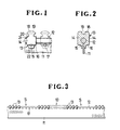
- FIGS 1 through 3 illustrate a slide fastener stringer 10 comprising an elongate stringer tape 11 having a longitudinal beaded edge 12 and a series of successive coupling elements 13 die-cast of metal or injection-molded of synthetic resin and mounted on the longitudinal beaded edge 12 at suitable intervals.
- each of the coupling elements 13 has two legs 14 mounted astride of the longitudinal beaded edge 12 and extending beyond the longitudinal beaded edge 12 over the opposite surfaces of the stringer tape 11.
- the legs 14 of each coupling element 13 are integrally interconnected by a connector 15 positioned at the rear ends 16 of the legs 14 and extending through a hole 17 defined in the stringer tape 11 near the beaded edge 12.
- the coupling elements 13 thus securely mounted on the stringer tape 11 are suitable especially for heavy-duty use where they are subject to undue lateral loads that would otherwise tend to rip off the coupling elements 13.
- Each of the coupling elements 13 has a coupling head 18 remote from the rear ends 16 of the legs 14 and having a recess 19, and a pair of ridges 20 on respective shoulders 21 spaced rearwardly from the coupling head 18.
- the recesses 19 of the coupling heads 18 receive the ridges 20 of the companion coupling elements to allow secure coupling engagement between the two meshing series of coupling elements.
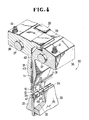
- FIGS 4 and 5 show an apparatus for removing coupling elements 13 from a slide fastener stringer tape 11, the apparatus being generally denoted at 30.
- the apparatus 30 essentially comprises a pair of grippers 31 for gripping the slide fastener stringer tape 11 therebetween with the coupling elements 13 positioned downwardly, a central punch 32 disposed below the grippers 31 for thrusting into the coupling heads 18 to break the coupling elements 13 each into two pieces, and a pair of side punches 33 disposed one on each side of the central punch 32 and having wedge-shaped spreaders 34, respectively, on their upper ends for spreading the broken pieces of the coupling elements 13.
- the grippers 31 have lower supporting edges 35, respectively, on their lower ends. When the stringer tape 11 is clamped between the grippers 31, the ends of the tongues 22 of the coupling elements 13 are held against the supporting edges 35 for immovably supporting the coupling elements 13 on the grippers 31.
- the grippers 31 have upper foot members 36 angularly movably supported by parallel shafts 37, respectively, connected to an upper block 38.
- the upper foot members 36 have upper surfaces 39 engaged by a piston rod 40 of an air cylinder (not shown) mounted on the upper block 38. When the air cylinder is actuated to extend the piston rod 40, the upper surfaces 39 are pushed downwardly to cause the grippers 31 to turn in opposite directions about the shafts 37 for spreading the lower ends thereof apart from each other.
- the grippers 31 are normally urged by compression coil springs 41 acting between the grippers 31 and the upper block 38 to turn in a direction to bring their lower ends together. Between the upper foot members 36, there is disposed a spacer 42 for keeping the lower ends of the grippers 31 spaced a certain distance from each other when the grippers 31 are brought together under the-resiliency of the compression coil springs 41, the distance being selected to be slightly greater than the thickness of the stringer tape 11. Therefore, even when the stringer tape 11 is gripped between the grippers 31, the stringer tape 11 can be moved in its longitudinal direction.
- the grippers 31, when brought together, jointly define a cavity 43 therebetween.
- the upper block 38 is vertically movable a certain stroke by a suitable drive source such as an air cylinder (not shown) for the reason described below.
- the central punch 32 is vertically movable a certain stroke toward the grippers 31 by a suitable drive source such as an air cylinder (not shown) disposed below a fixed lower block 44 ( Figure 5).
- the central punch 32 has as many cutting edges 45 on its upper end as the number of coupling elements 13 to be removed from the stringer tape 11, the cutting edges 45 being spaced at equal intervals in the longitudinal direction of the central punch 32.
- Each of the cutting edges 45 is of a triangular cross section.
- the central punch 32 also has a plurality of tape displacers 46 positioned on the upper end thereof between adjacent ones of the cutting edges 45 and projecting toward the grippers 31.
- the tape displacers 46 have upwardly opening recesses 47 defined respectively in upper ends thereof for receiving the beaded edge 12 of the stringer tape 11.
- the recesses 47 have lower bottoms higher than the tips of the cutting edges 45.
- the side punches 33 are vertically movable a certain stroke toward the grippers 31 by another suitable drive source such as an air cylinder (not shown) disposed below the lower block 44.
- Each of the wedge-shaped spreaders 34 has a length corresponding to that of the succession of coupling elements 13 to be removed, and has its uppermost tip positioned closely to the central punch 32.
- the side punches 33 have respective legs 48 vetically slidably disposed in the lower block 44. Compression coil springs 49 are interposed between the lower block 44 and the legs 48 for normally urging the side punches 33 to move downwardly away from the grippers 31.
- the central punch 32 is mounted on a punch support 50 slidably disposed between the side punch legs 48.
- the central punch 32 is normally urged to move downwardly away from the grippers 31 by compression coil springs 51 acting between the punch support 50 and the side punch legs 48.
- the central punch 32 and the side punches 31 are thus interlinked by the compression coil spring 51 such that when the side punches 33 are lowered, the central punch 32 is also lowered therewith to allow the stringer tape 11 to be longitudinally delivered smoothly and safely after removal of coupling elements 13 therefrom.
- the central punch 32 and the side punches 33 are moved upwardly by the respective drive sources until the tips of the spreaders 33 engage the coupling heads 18 to hold the coupling elements 13 stably in position between the supporting edges 35 and the spreaders 33, as shown in Figure 6A. Thereafter, only the central punch 32 continues to be moved upwardly to cause the cutting edges 45 to reach the bottoms of the recesses 19 in the coupling heads 18, as shown in Figure 6B. Continued upward movement of the central punch 32 enables the cutting edges 45 to thrust into the coupling elements 13 toward the beaded edge 12, thus cutting off the coupling heads 18 into two halves, as shown in Figure 6C. During this time, the tape displacers 46 reach the beaded edge 12 of the stringer tape 11 and their recesses 47 push the beaded edge 12 upwardly away from the cutting edges 45, so that the beaded edge 12 will not be damaged by the cutting edges 45.
- the spreaders 33 of the side punches 33 are driven upwardly to force the separated coupling heads 18 further apart, producing a crack 52 in each of the connectors 15 as shown in Figure 6C.
- the spreaders 34 are wedged into each of the coupling elements 13 to break it all the way into two pieces 53, as shown in Figure 6D, whereupon the coupling element pieces 53 come off the stringer tape 11.
- the central punch 32 is also moved upwardly at this time to cause the tape displacers 46 to lift the beaded edge 12 for thereby pushing the stringer tape 11 into the cavity 43 between the grippers 31.
- the piston rod 40 is lowered to turn the grippers 31 away from each other about the respective shafts 37 and, at the same time, the upper block 38 is lowered.
- the grippers 31 with their lower ends spaced from each other are now moved downwardly along the outer sides of the side punches 33, as shown in Figure 6E, for positively and reliably removing coupling element pieces 53 from the stringer tape 11.
- the piston rod 40 and the upper block 40 are moved back upwardly to cause the grippers 31 to grip the stringer tape 11.
- the cental punch 32 and the side punches 33 are moved back downwardly.
- the stringer tape 11 as it is gripped between the grippers 31 is longitudinally fed along until a next portion thereof from which coupling elements 13 are to be removed is supported by the grippers 31.
- the stringer tape 11 may be longitudinally fed along when the grippers 31 are spaced apart from each ohter as shown in Figure 6E.
Landscapes
- Slide Fasteners (AREA)
Abstract
Description
- The present invention relates to a method of and an apparatus for removing coupling elements from a slide fastener stringer tape.
- There are known methods of and apparatus for removing a number of successive coupling elements, which may be either die-cast of metal or injection-molded of synthetic resin, from the beaded edge of a slide fastener stringer tape to provide an element-free space across which the stringer tape will be cut off. One conventional arrangement for such coupling element removal, illustrated in Figure 7 of the accompanying drawings, is disclosed in Japanese Patent Publication No. 57-61406 published on December 24,1982. According to this prior design, each of coupling elements A to be removed from a slide fastener stringer tape E is cut off into two halves by thrusting a wedge-shaped cutter C into the coupling head of the coupling element A while at the same time spreading out tape grippers D to cause their ends to force two coupling element legs B apart off the stringer tape E.
- The above known process is effective in removing slide fastener coupling elements of the type which has legs attached simply astride of a longitudinal beaded edge of a slide fastener stringer tape. Some slide fasteners have coupling elements that are firmly anchored on a slide fastener H stringer tape. Each of the coupling elements has two legs mounted astride of a longitudinal beaded edge of a slide fastener stringer tape and interconnected by a connector extending through a hole defined in the stringer tape and covered by the legs. Coupling elements of this type cannot be removed from the stringer tape by the arrangement disclosed in the foregoing publication.
- The present invention seeks to provide a method of removing coupling elements from a longitudinal beaded edge of a slide fastener stringer tape, the coupling elements each having two legs integrally interconnected by a connector extending through the stringer tape.
- The present invention further seeks to provide an apparatus for carrying out the above method.
- According to a first aspect of the present invention, there is provided a method of removing coupling elements from a slide fastener stringer tape, each of the coupling elements having a coupling head and two legs extending from the coupling head and mounted astride of a longitudinal beaded edge of the stringer tape, said legs being integrally interconnected by a connector extending through the stringer tape, said method comprising the steps of: gripping said stringer tape between a pair of grippers with said coupling elements supported on said grippers; thrusting cutting edges into the coupling head of each coupling element toward said longitudinal beaded edge to break the coupling head; and driving wedge-shaped spreaders into said each coupling element through the broken coupling head thereof to spread said each coupling element until said connector is forcibly broken, for thereby breaking said each coupling element into two pieces off said stringer tape.
- According to a second aspect of the present invention, there is provided an apparatus for removing coupling elements from a slide fastener stringer tape, each of the coupling elements having a coupling head and two legs extending from the coupling head and mounted astride of a longitudinal beaded edge of the stringer tape, said legs being integrally interconnected by a connector extending through the stringer tape, said apparatus comprising: means for gripping said stringer tape while supporting said coupling elements; means for thrusting into the coupling head of each coupling element toward said longitudinal beaded edge to break the coupling head; and means for spreading said each coupling element through the broken coupling head thereof until said connector is forcibly broken, for thereby breaking said each coupling element into two pieces off said stringer tape.
- Many other advantages and features of the present invention will become manifest to those versed in the art upon making reference to the detailed description and the accompanying sheets of drawings in which a preferred structural embodiment incorporating the principles of the present invention is shown by way of illustrative example.
- Figure 1 is an enlarged fragmentary plan view of a coupling element mounted on a longitudinal beaded edge of a slide fastener stringer tape;
- Figure 2 is a cross-sectional view of the coupling element shown in Figure 1;
- Figure 3 is a fragmentary plan view of a slide fastener stringer with coupling elements mounted on a longitudinal beaded edge of a slide fastener stringer tape;
- Figure 4 is a fragmentary perspective view, partly in cross section, of an apparatus for removing coupling elements from a slide fastener stringer tape according to the present invention;
- Figure 5 is a fragmentary vertical cross-sectional view of the apparatus illustrated in Figure 4;
- Figures 6A through 6E are fragmentary cross-sectional views showing a sequence of progressive steps of coupling element removal; and
- Figure 7 is a fragmentary vertical cross-sectional view of a conventional apparatus for removing coupling elements from a slide fastener stringer tape.
- Figures 1 through 3 illustrate a
slide fastener stringer 10 comprising anelongate stringer tape 11 having a longitudinalbeaded edge 12 and a series ofsuccessive coupling elements 13 die-cast of metal or injection-molded of synthetic resin and mounted on the longitudinal beadededge 12 at suitable intervals. As shown Figures 1 and 2, each of thecoupling elements 13 has twolegs 14 mounted astride of the longitudinalbeaded edge 12 and extending beyond the longitudinalbeaded edge 12 over the opposite surfaces of thestringer tape 11. To anchor thecoupling elements 13 firmly on thestringer tape 11, thelegs 14 of eachcoupling element 13 are integrally interconnected by aconnector 15 positioned at therear ends 16 of thelegs 14 and extending through ahole 17 defined in thestringer tape 11 near thebeaded edge 12. Thecoupling elements 13 thus securely mounted on thestringer tape 11 are suitable especially for heavy-duty use where they are subject to undue lateral loads that would otherwise tend to rip off thecoupling elements 13. - Each of the
coupling elements 13 has acoupling head 18 remote from therear ends 16 of thelegs 14 and having arecess 19, and a pair ofridges 20 onrespective shoulders 21 spaced rearwardly from thecoupling head 18. When the series ofcoupling elements 13 and another series of companion coupling elements (not shown) are brought into intermeshing engagement by a slider - (not shown) to close a slide fastener, therecesses 19 of thecoupling heads 18 receive theridges 20 of the companion coupling elements to allow secure coupling engagement between the two meshing series of coupling elements. From therear end 16 of eachcoupling element leg 14, there extends athin tongue 22 in contact with thestringer tape 11, thetongue 22 serving as a guide for the slider as it moves along the series ofcoupling elements 13 to open or close the slide fastener. - According to the present invention, a certain successive number of
such coupling elements 13 are removed from thestringer tape 11 to provide an element-free space S (Figure 3) across which theslide fastener stringer 10 will be cut off. - Figures 4 and 5 show an apparatus for removing
coupling elements 13 from a slidefastener stringer tape 11, the apparatus being generally denoted at 30. Theapparatus 30 essentially comprises a pair ofgrippers 31 for gripping the slidefastener stringer tape 11 therebetween with thecoupling elements 13 positioned downwardly, acentral punch 32 disposed below thegrippers 31 for thrusting into thecoupling heads 18 to break thecoupling elements 13 each into two pieces, and a pair ofside punches 33 disposed one on each side of thecentral punch 32 and having wedge-shaped spreaders 34, respectively, on their upper ends for spreading the broken pieces of thecoupling elements 13. - The
grippers 31 have lower supportingedges 35, respectively, on their lower ends. When thestringer tape 11 is clamped between thegrippers 31, the ends of thetongues 22 of thecoupling elements 13 are held against the supportingedges 35 for immovably supporting thecoupling elements 13 on thegrippers 31. Thegrippers 31 haveupper foot members 36 angularly movably supported byparallel shafts 37, respectively, connected to anupper block 38. Theupper foot members 36 haveupper surfaces 39 engaged by apiston rod 40 of an air cylinder (not shown) mounted on theupper block 38. When the air cylinder is actuated to extend thepiston rod 40, theupper surfaces 39 are pushed downwardly to cause thegrippers 31 to turn in opposite directions about theshafts 37 for spreading the lower ends thereof apart from each other. Thegrippers 31 are normally urged bycompression coil springs 41 acting between thegrippers 31 and theupper block 38 to turn in a direction to bring their lower ends together. Between theupper foot members 36, there is disposed aspacer 42 for keeping the lower ends of thegrippers 31 spaced a certain distance from each other when thegrippers 31 are brought together under the-resiliency of thecompression coil springs 41, the distance being selected to be slightly greater than the thickness of thestringer tape 11. Therefore, even when thestringer tape 11 is gripped between thegrippers 31, thestringer tape 11 can be moved in its longitudinal direction. Thegrippers 31, when brought together, jointly define acavity 43 therebetween. Theupper block 38 is vertically movable a certain stroke by a suitable drive source such as an air cylinder (not shown) for the reason described below. - The
central punch 32 is vertically movable a certain stroke toward thegrippers 31 by a suitable drive source such as an air cylinder (not shown) disposed below a fixed lower block 44 (Figure 5). Thecentral punch 32 has asmany cutting edges 45 on its upper end as the number ofcoupling elements 13 to be removed from thestringer tape 11, thecutting edges 45 being spaced at equal intervals in the longitudinal direction of thecentral punch 32. Each of thecutting edges 45 is of a triangular cross section. Thecentral punch 32 also has a plurality oftape displacers 46 positioned on the upper end thereof between adjacent ones of thecutting edges 45 and projecting toward thegrippers 31. Thetape displacers 46 have upwardly openingrecesses 47 defined respectively in upper ends thereof for receiving thebeaded edge 12 of thestringer tape 11. Therecesses 47 have lower bottoms higher than the tips of thecutting edges 45. - The
side punches 33 are vertically movable a certain stroke toward thegrippers 31 by another suitable drive source such as an air cylinder (not shown) disposed below thelower block 44. Each of the wedge-shaped spreaders 34 has a length corresponding to that of the succession ofcoupling elements 13 to be removed, and has its uppermost tip positioned closely to thecentral punch 32. Theside punches 33 haverespective legs 48 vetically slidably disposed in thelower block 44.Compression coil springs 49 are interposed between thelower block 44 and thelegs 48 for normally urging theside punches 33 to move downwardly away from thegrippers 31. Thecentral punch 32 is mounted on apunch support 50 slidably disposed between theside punch legs 48. Thecentral punch 32 is normally urged to move downwardly away from thegrippers 31 bycompression coil springs 51 acting between thepunch support 50 and theside punch legs 48.. Thecentral punch 32 and theside punches 31 are thus interlinked by thecompression coil spring 51 such that when theside punches 33 are lowered, thecentral punch 32 is also lowered therewith to allow thestringer tape 11 to be longitudinally delivered smoothly and safely after removal ofcoupling elements 13 therefrom. - Operation of the
apparatus 30 for removingcoupling elements 13 from thestringer tape 11'.will be described with reference to Figures 6A through 6E. - In preparation for coupling element removal, a portion of the
stringer tape 11 from whichcoupling elements 13 are to be removed is sandwiched between thegrippers 31 with the ends of thetongues 22 held against the supportingedges 35 to hold thecoupling elements 13 in position. Thecentral punch 32 and theside punches 33 are retracted to their lowermost positions below thegrippers 31, and thecutting edges 45 and thetape displacers 46 are positioned slighly beneath the tips of thespreaders 34 of theside punches 33. - The
central punch 32 and theside punches 33 are moved upwardly by the respective drive sources until the tips of thespreaders 33 engage thecoupling heads 18 to hold thecoupling elements 13 stably in position between the supportingedges 35 and thespreaders 33, as shown in Figure 6A. Thereafter, only thecentral punch 32 continues to be moved upwardly to cause thecutting edges 45 to reach the bottoms of therecesses 19 in thecoupling heads 18, as shown in Figure 6B. Continued upward movement of thecentral punch 32 enables thecutting edges 45 to thrust into thecoupling elements 13 toward thebeaded edge 12, thus cutting off thecoupling heads 18 into two halves, as shown in Figure 6C. During this time, thetape displacers 46 reach thebeaded edge 12 of thestringer tape 11 and theirrecesses 47 push thebeaded edge 12 upwardly away from thecutting edges 45, so that thebeaded edge 12 will not be damaged by thecutting edges 45. - When the
coupling heads 18 are broken into two halves, thespreaders 33 of theside punches 33 are driven upwardly to force theseparated coupling heads 18 further apart, producing acrack 52 in each of theconnectors 15 as shown in Figure 6C. Upon further ascending movement of theside punches 33, thespreaders 34 are wedged into each of thecoupling elements 13 to break it all the way into twopieces 53, as shown in Figure 6D, whereupon thecoupling element pieces 53 come off thestringer tape 11. Thecentral punch 32 is also moved upwardly at this time to cause thetape displacers 46 to lift thebeaded edge 12 for thereby pushing thestringer tape 11 into thecavity 43 between thegrippers 31. This upward movement of thebeaded edge 12 and hence thestringer tape 11 assists in breaking thecoupling elements 13 for complete removal thereof from thestringer tape 11. At this time, thestringer tape 11 can be lifted unobstructedly between thegrippers 31 since there is a suitable gap provided between thegrippers 31 by thespacer 42, as described above. - - Immediatety after each
coupling element 13 is split into itspieces 53, thepiston rod 40 is lowered to turn thegrippers 31 away from each other about therespective shafts 37 and, at the same time, theupper block 38 is lowered. Thegrippers 31 with their lower ends spaced from each other are now moved downwardly along the outer sides of the side punches 33, as shown in Figure 6E, for positively and reliably removingcoupling element pieces 53 from thestringer tape 11. Thereafter, thepiston rod 40 and theupper block 40 are moved back upwardly to cause thegrippers 31 to grip thestringer tape 11. Then, thecental punch 32 and the side punches 33 are moved back downwardly. Thestringer tape 11 as it is gripped between thegrippers 31 is longitudinally fed along until a next portion thereof from whichcoupling elements 13 are to be removed is supported by thegrippers 31. Altematively, thestringer tape 11 may be longitudinally fed along when thegrippers 31 are spaced apart from each ohter as shown in Figure 6E. - The above cycle shown in Figures 6A through 6E is repeated to remove desired
coupling elements 13 from thestringer tape 11 for producing longitudinally spaced coupling-element free spaces S on thestringer tape 11 as shown in Figure 3.
Claims (7)
Applications Claiming Priority (2)
| Application Number | Priority Date | Filing Date | Title |
|---|---|---|---|
| JP125779/85 | 1985-06-10 | ||
| JP60125779A JPS61284203A (en) | 1985-06-10 | 1985-06-10 | Method and apparatus for removing teeth of slide fastener |
Publications (3)
| Publication Number | Publication Date |
|---|---|
| EP0205959A2 true EP0205959A2 (en) | 1986-12-30 |
| EP0205959A3 EP0205959A3 (en) | 1987-11-11 |
| EP0205959B1 EP0205959B1 (en) | 1990-08-08 |
Family
ID=14918631
Family Applications (1)
| Application Number | Title | Priority Date | Filing Date |
|---|---|---|---|
| EP19860107114 Expired - Lifetime EP0205959B1 (en) | 1985-06-10 | 1986-05-26 | Method of and apparatus for removing coupling elements from a slide fastener stringer tape |
Country Status (13)
| Country | Link |
|---|---|
| US (1) | US4831709A (en) |
| EP (1) | EP0205959B1 (en) |
| JP (1) | JPS61284203A (en) |
| KR (1) | KR870002120B1 (en) |
| AU (1) | AU559467B2 (en) |
| BR (1) | BR8602761A (en) |
| CA (1) | CA1307099C (en) |
| DE (1) | DE3673256D1 (en) |
| ES (1) | ES8703258A1 (en) |
| GB (1) | GB2176237B (en) |
| HK (1) | HK66990A (en) |
| MY (1) | MY101589A (en) |
| SG (1) | SG59190G (en) |
Families Citing this family (4)
| Publication number | Priority date | Publication date | Assignee | Title |
|---|---|---|---|---|
| JPH0649008B2 (en) * | 1989-07-10 | 1994-06-29 | 吉田工業株式会社 | Slide fastener chain space formation method |
| US6796234B1 (en) * | 1998-08-21 | 2004-09-28 | Rotec-Hulsensysteme Gmbh & Co. Kg | Holding device for flexographic printing sleeves |
| US20030230377A1 (en) * | 2002-06-14 | 2003-12-18 | Turvey Robert R. | Apparatus and method for automated splicing of closer tape |
| FR3025735B1 (en) * | 2014-09-17 | 2016-12-09 | Europe Tech | PROCESS FOR PROCESSING A COMPOSITE PIECE |
Citations (5)
| Publication number | Priority date | Publication date | Assignee | Title |
|---|---|---|---|---|
| FR2259667A1 (en) * | 1974-01-31 | 1975-08-29 | Yoshida Kogyo Kk | |
| GB2025514A (en) * | 1978-07-12 | 1980-01-23 | Yoshida Kogyo Kk | Removing fastener elements from a slide fastener chain |
| GB2034805A (en) * | 1978-11-16 | 1980-06-11 | Yoshida Kogyo Kk | Removing fastener elements from a slide fastener chain |
| US4413398A (en) * | 1981-09-21 | 1983-11-08 | Talon, Inc. | Slide fastener chain with leg remanents at gap and method and apparatus of manufacture |
| EP0150508A2 (en) * | 1983-12-29 | 1985-08-07 | Yoshida Kogyo K.K. | Method and apparatus for removing coupling elements from slide fastener stringers |
Family Cites Families (3)
| Publication number | Priority date | Publication date | Assignee | Title |
|---|---|---|---|---|
| US3426752A (en) * | 1967-01-03 | 1969-02-11 | Andrew J Laico | Cast spreader and breaker |
| DE2601383C2 (en) * | 1976-01-15 | 1977-09-08 | Opti Patent-, Forschungs- Und Fabrikations-Ag, Glarus (Schweiz) | Method and device for detaching zipper members made of thermoplastic from their support tapes |
| JPS5591304A (en) * | 1978-12-28 | 1980-07-10 | Yoshida Kogyo Kk | Device of preparing space of fastener chain |
-
1985
- 1985-06-10 JP JP60125779A patent/JPS61284203A/en active Granted
-
1986
- 1986-05-21 GB GB08612322A patent/GB2176237B/en not_active Expired
- 1986-05-23 AU AU57876/86A patent/AU559467B2/en not_active Ceased
- 1986-05-26 EP EP19860107114 patent/EP0205959B1/en not_active Expired - Lifetime
- 1986-05-26 CA CA000509929A patent/CA1307099C/en not_active Expired - Lifetime
- 1986-05-26 DE DE8686107114T patent/DE3673256D1/en not_active Expired - Lifetime
- 1986-06-06 BR BR8602761A patent/BR8602761A/en not_active Application Discontinuation
- 1986-06-09 KR KR1019860004546A patent/KR870002120B1/en not_active IP Right Cessation
- 1986-06-09 ES ES555850A patent/ES8703258A1/en not_active Expired
-
1987
- 1987-07-24 MY MYPI87001097A patent/MY101589A/en unknown
-
1988
- 1988-02-01 US US07/153,570 patent/US4831709A/en not_active Expired - Fee Related
-
1990
- 1990-07-17 SG SG591/90A patent/SG59190G/en unknown
- 1990-08-23 HK HK669/90A patent/HK66990A/en unknown
Patent Citations (5)
| Publication number | Priority date | Publication date | Assignee | Title |
|---|---|---|---|---|
| FR2259667A1 (en) * | 1974-01-31 | 1975-08-29 | Yoshida Kogyo Kk | |
| GB2025514A (en) * | 1978-07-12 | 1980-01-23 | Yoshida Kogyo Kk | Removing fastener elements from a slide fastener chain |
| GB2034805A (en) * | 1978-11-16 | 1980-06-11 | Yoshida Kogyo Kk | Removing fastener elements from a slide fastener chain |
| US4413398A (en) * | 1981-09-21 | 1983-11-08 | Talon, Inc. | Slide fastener chain with leg remanents at gap and method and apparatus of manufacture |
| EP0150508A2 (en) * | 1983-12-29 | 1985-08-07 | Yoshida Kogyo K.K. | Method and apparatus for removing coupling elements from slide fastener stringers |
Also Published As
| Publication number | Publication date |
|---|---|
| ES8703258A1 (en) | 1987-03-01 |
| AU559467B2 (en) | 1987-03-12 |
| KR870002120B1 (en) | 1987-12-09 |
| EP0205959B1 (en) | 1990-08-08 |
| SG59190G (en) | 1990-09-07 |
| US4831709A (en) | 1989-05-23 |
| KR870000038A (en) | 1987-02-16 |
| BR8602761A (en) | 1987-02-10 |
| JPH0123125B2 (en) | 1989-05-01 |
| GB8612322D0 (en) | 1986-06-25 |
| DE3673256D1 (en) | 1990-09-13 |
| ES555850A0 (en) | 1987-03-01 |
| JPS61284203A (en) | 1986-12-15 |
| EP0205959A3 (en) | 1987-11-11 |
| GB2176237B (en) | 1989-01-18 |
| GB2176237A (en) | 1986-12-17 |
| AU5787686A (en) | 1986-12-18 |
| MY101589A (en) | 1991-12-17 |
| CA1307099C (en) | 1992-09-08 |
| HK66990A (en) | 1990-08-31 |
Similar Documents
| Publication | Publication Date | Title |
|---|---|---|
| EP0608770B1 (en) | Slide-fastener coupling element and method of making the same | |
| EP0630706B1 (en) | A method and apparatus for forming slide-fastener coupling element | |
| EP0205959B1 (en) | Method of and apparatus for removing coupling elements from a slide fastener stringer tape | |
| EP0396373B1 (en) | Method of and apparatus for applying top end stops on to a slide fastener chain | |
| EP0083103B1 (en) | Method and apparatus for assembling sliders on an uncut fastener chain | |
| EP0302299B1 (en) | Method of manufacturing separable slide fastener | |
| EP0129757B1 (en) | Formation of element-free spaces in slide fastener chains | |
| KR860000685B1 (en) | Fastener stringer's forming method and apparatus | |
| EP0172546B1 (en) | A space portion processing method and apparatus for a slide fastener chain | |
| EP0488816B1 (en) | Method and apparatus for forming element-free spaces in slide fastener chain | |
| EP0468334B1 (en) | Apparatus for gapping a stringer chain | |
| EP0083112B1 (en) | An apparatus and a method for forming space sections in a slide fastener chain having coupling elements in the form of continuous coil | |
| KR880000594Y1 (en) | Apparatus for attaching top end stops to a continuous slide fastener chain | |
| EP0303215B1 (en) | Apparatus for attaching top end stops to slide fastener chain | |
| JPH0759207B2 (en) | Slide fastener chain space creation method and cutter used for this | |
| EP0097342B1 (en) | Apparatus for automatically threading separable slide fastener stringers through sliders | |
| JPS6348521B2 (en) |
Legal Events
| Date | Code | Title | Description |
|---|---|---|---|
| PUAI | Public reference made under article 153(3) epc to a published international application that has entered the european phase |
Free format text: ORIGINAL CODE: 0009012 |
|
| AK | Designated contracting states |
Kind code of ref document: A2 Designated state(s): BE DE FR IT NL |
|
| PUAL | Search report despatched |
Free format text: ORIGINAL CODE: 0009013 |
|
| AK | Designated contracting states |
Kind code of ref document: A3 Designated state(s): BE DE FR IT NL |
|
| 17P | Request for examination filed |
Effective date: 19880211 |
|
| 17Q | First examination report despatched |
Effective date: 19890127 |
|
| GRAA | (expected) grant |
Free format text: ORIGINAL CODE: 0009210 |
|
| AK | Designated contracting states |
Kind code of ref document: B1 Designated state(s): BE DE FR IT NL |
|
| PG25 | Lapsed in a contracting state [announced via postgrant information from national office to epo] |
Ref country code: IT Free format text: LAPSE BECAUSE OF FAILURE TO SUBMIT A TRANSLATION OF THE DESCRIPTION OR TO PAY THE FEE WITHIN THE PRE;WARNING: LAPSES OF ITALIAN PATENTS WITH EFFECTIVE DATE BEFORE 2007 MAY HAVE OCCURRED AT ANY TIME BEFORE 2007. THE CORRECT EFFECTIVE DATE MAY BE DIFFERENT FROM THE ONE RECORDED.SCRIBED TIME-LIMIT Effective date: 19900808 |
|
| ET | Fr: translation filed | ||
| REF | Corresponds to: |
Ref document number: 3673256 Country of ref document: DE Date of ref document: 19900913 |
|
| RIN2 | Information on inventor provided after grant (corrected) |
Free format text: YOSHIMURA, EIICHI |
|
| PLBE | No opposition filed within time limit |
Free format text: ORIGINAL CODE: 0009261 |
|
| STAA | Information on the status of an ep patent application or granted ep patent |
Free format text: STATUS: NO OPPOSITION FILED WITHIN TIME LIMIT |
|
| 26N | No opposition filed | ||
| ITTA | It: last paid annual fee | ||
| PGFP | Annual fee paid to national office [announced via postgrant information from national office to epo] |
Ref country code: FR Payment date: 19940420 Year of fee payment: 9 |
|
| PGFP | Annual fee paid to national office [announced via postgrant information from national office to epo] |
Ref country code: DE Payment date: 19940531 Year of fee payment: 9 Ref country code: NL Payment date: 19940531 Year of fee payment: 9 |
|
| ITPR | It: changes in ownership of a european patent |
Owner name: CAMBIO RAGIONE SOCIALE;YKK CORPORATION |
|
| REG | Reference to a national code |
Ref country code: FR Ref legal event code: CD |
|
| PGFP | Annual fee paid to national office [announced via postgrant information from national office to epo] |
Ref country code: BE Payment date: 19950302 Year of fee payment: 10 |
|
| NLT1 | Nl: modifications of names registered in virtue of documents presented to the patent office pursuant to art. 16 a, paragraph 1 |
Owner name: YKK CORPORATION TE TOKIO, JAPAN. |
|
| PG25 | Lapsed in a contracting state [announced via postgrant information from national office to epo] |
Ref country code: NL Effective date: 19951201 |
|
| NLV4 | Nl: lapsed or anulled due to non-payment of the annual fee |
Effective date: 19951201 |
|
| PG25 | Lapsed in a contracting state [announced via postgrant information from national office to epo] |
Ref country code: DE Effective date: 19960201 |
|
| PG25 | Lapsed in a contracting state [announced via postgrant information from national office to epo] |
Ref country code: FR Effective date: 19960229 |
|
| REG | Reference to a national code |
Ref country code: FR Ref legal event code: ST |
|
| REG | Reference to a national code |
Ref country code: FR Ref legal event code: ST |
|
| PG25 | Lapsed in a contracting state [announced via postgrant information from national office to epo] |
Ref country code: BE Effective date: 19960531 |
|
| BERE | Be: lapsed |
Owner name: YKK CORP. Effective date: 19960531 |