EP0202919A1 - Time base error correctors - Google Patents
Time base error correctors Download PDFInfo
- Publication number
- EP0202919A1 EP0202919A1 EP86303829A EP86303829A EP0202919A1 EP 0202919 A1 EP0202919 A1 EP 0202919A1 EP 86303829 A EP86303829 A EP 86303829A EP 86303829 A EP86303829 A EP 86303829A EP 0202919 A1 EP0202919 A1 EP 0202919A1
- Authority
- EP
- European Patent Office
- Prior art keywords
- signal
- line
- field
- carrier
- odd
- Prior art date
- Legal status (The legal status is an assumption and is not a legal conclusion. Google has not performed a legal analysis and makes no representation as to the accuracy of the status listed.)
- Granted
Links
- 230000004044 response Effects 0.000 claims description 29
- 238000001514 detection method Methods 0.000 claims description 14
- 210000002568 pbsc Anatomy 0.000 claims description 10
- 230000000694 effects Effects 0.000 claims description 2
- 239000012720 thermal barrier coating Substances 0.000 description 9
- 239000002131 composite material Substances 0.000 description 6
- 238000010586 diagram Methods 0.000 description 5
- 239000000203 mixture Substances 0.000 description 5
- 239000000969 carrier Substances 0.000 description 4
- 230000001360 synchronised effect Effects 0.000 description 4
- 238000000034 method Methods 0.000 description 3
- 101000598025 Homo sapiens Talin-1 Proteins 0.000 description 2
- 102100036977 Talin-1 Human genes 0.000 description 2
- 230000003534 oscillatory effect Effects 0.000 description 2
- 238000006243 chemical reaction Methods 0.000 description 1
- 230000006870 function Effects 0.000 description 1
- 230000010355 oscillation Effects 0.000 description 1
- 230000000717 retained effect Effects 0.000 description 1
Images


Classifications
-
- H—ELECTRICITY
- H04—ELECTRIC COMMUNICATION TECHNIQUE
- H04N—PICTORIAL COMMUNICATION, e.g. TELEVISION
- H04N5/00—Details of television systems
- H04N5/76—Television signal recording
- H04N5/91—Television signal processing therefor
- H04N5/93—Regeneration of the television signal or of selected parts thereof
- H04N5/95—Time-base error compensation
-
- H—ELECTRICITY
- H04—ELECTRIC COMMUNICATION TECHNIQUE
- H04N—PICTORIAL COMMUNICATION, e.g. TELEVISION
- H04N9/00—Details of colour television systems
- H04N9/79—Processing of colour television signals in connection with recording
- H04N9/87—Regeneration of colour television signals
- H04N9/89—Time-base error compensation
- H04N9/896—Time-base error compensation using a digital memory with independent write-in and read-out clock generators
Landscapes
- Engineering & Computer Science (AREA)
- Multimedia (AREA)
- Signal Processing (AREA)
- Television Signal Processing For Recording (AREA)
- Processing Of Color Television Signals (AREA)
Abstract
Description
- This invention relates to time base error correctors. More particularly, but not exclusively, the invention relates to a chrominance sub-carrier phase corrector incorporated in a time base error corrector for a video tape recorder (VTR) operated, in particular, in chrominance sub-carrier return mode, such that a write pulse supplied from a phase locked loop (PLL) circuit to a time base error corrector (TBC) is fed back to an automatic phase controller (APC) of the VTR.
- In a so-called low-band conversion recording system VTR in which the chrominance sub-carrier of a colour television signal is recorded on a magnetic tape after having been frequency converted to the low band side of the luminance signal, a frequency converter for inversely converting the frequency of the sub-carrier to the high band side of the luminance signal in the reproduction mode is incorporated in a loop of the APC circuit, so that when the frequency of the chrominance signal is inversely converted, the phase of the chrominance signal is locked to the phase of the oscillation output of the reference oscillator by the APC circuit.
- The chrominance signal thus inversely frequency converted is added to the luminance signal reproduced from the magnetic tape and then supplied as a composite video reproduction signal for the VTR.
- In order to eliminate jitter included in the composite video reproduction signal from the VTR, TBCs have been used such that the composite video reproduction signal of the VTR is written in a buffer memory in response to a write pulse signal including jitter, but the stored data are read out in response to a read pulse signal formed on the basis of the reference video signal in order to obtain the composite video signal synchronized with the reference video signal and including no jitter.
- In these TBCs, the oscillatory output of a PLL circuit for receiving the horizontal synchronizing signal included in the composite video reproduction signal from the VTR is used as the write pulse signal for the buffer memory, and the write pulse signal including jitter is formed on the basis of the locking operation of this PLL circuit to the horizontal synchronizing signal.
- Since the chrominance signal reproduced from the magnetic tape is phase locked by the APC circuit, no jitter is included in the chrominance signal obtained from the APC circuit. However, if the time base error correction is made by the TPC on the basis of jitter for the chrominance signal, jitter is included in the chrominance signal.
- To overcome these problems, as disclosed, for example, in Japanese published unexamined patent specification No. 53/46224, a method of feeding back the write pulse signal supplied from the PLL circuit to the TBC to the APC circuit to the VTR has been adopted as a return sub-carrier system. In this system, the return sub-carrier signal supplied from the PLL circuit to the VTR is added to an oscillatory output of a variable frequency oscillator which forms the APC circuit of the VTR, and is then supplied to the frequency converter, so that jitter can be incluoed in the chrominance signal whose frequency is inversely converted, by controiling the output frequency of the frequency converter according to frequency fluctuations of the return sub-carrier signal including jitter.
- In the TBC configured as described above, however, since the principle is based upon the fact that the timing of the synchronizing signal included in the video signal after time base error has been corrected and the phase of the burst signal are both replaced by the reference video signal, the chrominance burst signal (referred to as the burst signal) included in the output video signal should match in phase the burst signal included in the reference video signal. Therefore, it may be possible to discriminate whether or not the signal is replaced correctly by comparing the phase of the burst signal included in the video signal read out of the buffer memory with the phase of the burst signal included in the reference video signal. However, even when the system is thus configured, there still exists a problem in that since the chrominance signal for the succeeding line has already been written in the buffer memory when the mismatching in phase is detected between the two, there are time intervals during which the burst signal of the output video signal does not match in phase the burst signal of the reference video signal with respect to the chrominance signals for the lines already written in the buffer memory. Thus, it is impossible to obtain correct colour during the above mismatching time intervals.
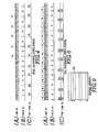
- On the other hand, in the TBC, in order to read the video signal from the buffer memory after the video signal from the VTR has once been written in the buffer memory, the VTR is so servo-controlled that the reproduced VTR signal VMIN as shown in Figure 8A of the accompanying drawings is advanced in phase with respect to the reference video signal VREF as shown in Figure 88 of the accompanying drawings. In this method, when seeing the n-th line Ln by taking the line immediately after the vertical synchronizing signal VSYNC as a top line, the reproduced video signals VMIN are written in the buffer memory in the order of
line address numbers - In the V lock VTR as described above, it is detected whether or not the phase of the burst signal included in the chrominance signal of the n-th line Ln of the time base error corrected video signal V TBC matches the phase of the burst signal included in the n-th line Ln of the reference video signal VREF, at the timing of reading of the n-th line Ln data of the reference video signal VREF. In this case, when the former does not match the latter, even if the phase of the burst signal of the input video signal written in the buffer memory is corrected thereafter so as to match the phase of the burst signal of the reference video signal, with respect to the data written in the buffer memory BM from the time when the n-th line Ln data of the reproduced video signal VMIN has been written in the buffer memory BM to the time when the written data is read as the time base error corrected video signal VTBC, the relative phase of the chrominance signal to the burst signal of the video signal does not match the relative phase of that to the burst signal of the reference video signal VREF*
- According to the present invention there is provided a time base error corrector for supplying an output video signal having no time base error by writing an input video signal in a buffer memory in response to a synchronizing signal included in the input video signal and by reading the written video signal from the buffer memory in response to a synchronizing signal included in a reference video signal;
characterised by: - means for controlling the phase of a chrominance sub-carrier included in the input video signal, before the input video signal is written in the buffer memory, so that the phase of a chrominance sub-carrier included in the read video signal matches that of a chrominance sub-carrier included in the reference video signal when the video signal written in the buffer memory is read therefrom in response to the reference video signal.
- Thus an embodiment of the present invention may provide a chrominance sub-carrier phase corrector for a TBC whereby the phase of the chrominance sub-carrier included in the input video signal is controlled, before the input video signal is written in the buffer memory, in such a way that the phase of the chrominance sub-carrier included in the video signal matches that of the chrominance sub-carrier included in the reference video signal when the video signal written in the buffer memory is read therefrom in response to the reference video signal.
- To achieve this, in the case of the NTSC system, a first non-inverted return sub-carrier signal is generated when the succeeding top line identification is determined to be an odd number, but a second inverted return sub-carrier signal is generated when the succeeding top line identification is determined to be an even number, for instance, the above odd/even (O/E) top line identification is predicted on the basis of the content O/E of the preceding field identification and the content O/E of the preceding field top line identification.
- Further, in the case of the PAL system, a first return sub-carrier signal is generated when two preceding top line identifications are determined to be an odd number and a non-inversion mode; a second return sub-carrier signal 90 degrees out of phase with the first signal is generated when two preceding top line identifications are determined to be an even number and a non-inversion mode; a third return sub-carrier signal is generated when the two preceding top line identifications are determined to be an odd number and an inversion mode; and a fourth return sub-carrier signal is generated when the two preceding top line identifications are determined to be an even number and an inversion mode. The above O/E top line identification and the above inversion/non-inversion mode top line identification are predicted on the basis of a content O/E of the preceding field identification and contents O/E and inversion/non-inversion (I/NI) of the preceding field top line identifications. Further, in the PAL system, a V-axis inversion controller is additionally incorporated to generate a control signal to match the burst signal phase and the V-axis sub-carrier phase of the reproduced video signal with those of the reference video signal.
- In an embodiment of TBC according to the present invention, since the phase of the chrominance sub-carrier included in the input video signal is so controlled, before being written in the buffer memory, that the phase of the chrominance sub-carrier included in the read video signal matches that of the chrominance sub-carrier included in the reference video signal when the video signal is read from the buffer memory in response to the reference video signal, it is possible always to realize correct colour on a television screen even if the VTR is servo-controlled in such a way that the reproduced video signal is written in the buffer memory in advance of the reference video signal in phase, that is, in the case of the so-called vertical phase control method (V lock).
- The invention will now be described by way of example with reference to the accompanying drawings, throughout which like parts are referred to by like references, and in which:
- Figure 1 is a schematic block diagram showing a first embodiment of chrominance sub-carrier phase corrector for a time base corrector applicable to the NTSC colour television system;
- Figure 2 is a schematic block diagram showing a second embodiment of the chrominance sub-carrier phase corrector for a time base corrector applicable to the PAL system;
- Figure 3 is a chart showing the relationship between two waveform diagrams each representative of the phase relationship between the horizontal synchronizing signal and the burst signal of an odd line (A) and an even line (B) in the reference video signal of the NTSC colour television system;
- Figure 4 is a chart showing the relationship between three series of line identifications (IDs)(A), field IDs(B) and top line IDs(C) each represented by odd and even numbers in the reference video signal of the NTSC colour television system;
- Figure 5 is a chart showing the relationship between four waveform diagrams each representative of the phase relationship between the horizontal synchronizing signal and the burst signal of an odd line (+V axis) and non-inversion mode N (A or BURON), an even line (-V axis) and non-inversion mode N (B or BUREN), an odd line (+V axis) and inversion mode I (C or BURDI), and an even line (-V axis) and inversion mode I (D or BUR El) in the reference video signal of the PAL colour television system;
- Figure 6 is a chart showing the relationship between three series of line IDs(A), field IDs(B) and top line IDs(C) each represented by odd and even numbers and/or non-inversion and inversion mode in the reference video signal of the PAL colour television system;
- Figure 7 is a timing chart of waveforms showing various signals generated in the return sub-carrier generator shown in Figure 2;
- Figure 8 is a timing chart for assistance in explaining the time relationship between various signals necessary for when the video signals are written in or read out of the buffer memory in response to the reference video signal; and
- Figure 9 is a diagram showing line addresses arranged in the buffer memory.
- In the case of a composite video signal, the mutual phase relationship between the horizontal synchronizing signal and the burst signal (that is, the chrominance signal) is different in standardized television systems such as the NTSC colour television system, the PAL colour television system, etc. Therefore, embodiments of the present invention will be described for each colour television system.
- In the case of the NTSC colour television system, the relative phase relationship between the burst signal and the horizontal synchronizing signal is inverted for each line. That is, in odd lines if the burst signal BURO is generated after the end of the horizontal synchronizing signal HSYNC in phase with the signal HSYNC, for instance, as shown in Figure 3A, in even lines the burst signal BURE is generated 180 degrees out of phase with the signal HSYNC as shown in Figure 3B.
- On the other hand, in a TBC, a line top time point tT is previously determined to control writing and reading addresses in a buffer memory with an address at this time point tT as a top address. Therefore, it is possible to define a line identification signal (line ID) representative of the relative phase relationship between the burst signal and the horizontal synchronizing signal at each line by synchronizing the top time point tT with the zero-crossing points of the burst signals BURO and BURE. In other words, where the burst signal BURO crosses the zero point from the negative side to the positive side at the top time point tT as shown in Figure 3A, the line ID is defined as an odd number (represented by the symbol "O"). Where the burst signal BURE crosses the zero point from the positive side to the negative side at the top time point tT as shown in Figure 3B, the line ID is defined as an even number (represented by the symbol "E").
- Here, it should be noted that if the line top time point tT is set at the time point tTX shifted by a half period of the burst signal BURO or BURE, the definition of the line ID (that is, "O" and/or "E") is reversed. This means that the line ID is not an absolute definition but a relative definition. Therefore, it is possible freely to define the line ID on the basis of the line ID of the TBC reference video signal VREF.
- In the case of the reference video signal VREFI the relationship between the line ID and the field ID (that is, an odd or even number of the field signal) is continuous as shown in Figure 4. As shown in Figure 4A, the line ID is switched alternately from "O" to "E" or vice versa for each line. Further, the field ID is switched alternately from "O" to "E" or vice versa for each field as shown in Figure 4B. However, when seeing the line ID of the top line of each field (referred to as top line ID) as shown in Figure 4C, the top line ID of each field is switched alternately from "O" to "E" or vice versa every two fields because there exists an interlaced relationship in a series of the fields.
- With reference to the relationship between the IDs shown in Figures 4A to 4C, it is possible to know the relationship between the top line ID of each field and the field ID of the preceding field as follows: if the field ID of the preceding field is "E", the top line ID of the succeeding field is inverted from the top line ID of the preceding field. In contrast with this, if the field ID of the preceding field is "O", the content of the top line ID of the preceding field is not changed, but remains at the top line ID of the succeeding field.
- At the time point t10 in Figure 4, for instance, since the field ID of the preceding field is "E" in Figure 4B, the top line ID at the time point t10 is inverted from the content of "E" of the top line ID of the preceding field to "O".
- At the succeeding field top time point t11, since the field ID of the preceding field is "O", the top line ID of the succeeding field remains at "O" without changing from the content of "O" of the top line ID of the preceding field.
- At the succeeding field top time point t12, since the preceding field ID is "E", the succeeding field top line ID is inverted from the content "O" of the preceding field top line ID to "E".
- Moreover, at the succeeding field top time point t13, since the preceding field ID is "O", the succeeding field top line ID remains at "E" without changing from the content "E" of the preceding field top line ID.
- By paying attention to the fact that the reference video signal VREF has the relationship as shown in Figure 4, it is possible to predict the top line ID of the succeeding field on the basis of the content of the field ID of the preceding field and the content of the top line ID of the field one or more fields before the current field. Therefore, if the phase of the burst signal (that is, the sub-carrier) is forcibly replaced with another phase so that when the reproduced video signal (referred to as an input video signal) is written in the buffer memory, the burst signal may have top line IDs which match the predicted "O" or "E", it is possible to realize the time base error correcting operation such that the phase of the sub-carrier of the time base error corrected video signal (referred to as an output video signal) VTBC read out of the buffer memory allows matching of the phase of the sub-carrier of the reference video signal V REF at the top time point of the top line of the succeeding field.
- As described above, since it is possible to determine the phase of the output video signal VTBC of the field one or a plurality of fields after the current field on the basis of the information of the field one or a plurality of fields before the current field in writing top line data of an input video signal in the buffer memory, it is possible to supply an output video signal VTBC having a sub-carrier whose phase matches the phase of the sub-carrier of the reference video signal V REF in reading the output video signal VTBC from the buffer memory.
- Embodiments of TBC according to the present invention are so configured as to realize the above-mentioned operation.
- In Figure 1, an input video signal V MIN is converted into a digital signal by an analog-to-digital (A/D)
converter 11 and then written in abuffer memory 12. A write clock signal WCK used for this writing operation is generated from a writeclock signal generator 13 on the basis of a horizontal synchronizing signal HSYNC included in the input video signal VMIN, the frequency of which is selected to a frequency four times higher than the colour sub-carrier frequency (that is, 4 fcs). - The write
clock signal generator 13 further generates a line top pulse LTP to designate a head address in the memory area for each line in thebuffer memory 12. - Video data thus written in the
buffer memory 12 for each line are read in sequence in response to a read clock pulse RCK generated by a readclock signal generator 15, converted into an analog signal by a D/A converter 18, added to a reference synchronizing signal RSYNC and a reference burst signal RBURST by anadder 19, and then supplied as an output video signal V TBC* - Here, the read
clock signal generator 15 receives the horizontal synchronizing signal HSYNC and the burst signal BURST both included in the reference video signal VREF, and generates the read clock signal RCK having a frequency 4 fsc, and a reference horizontal pulse REFH having the same period of that of the horizontal synchronizing signal HSYNC. On the basis of this reference horizontal pulse REFH, a 1/2divider 16 is driven to generate a line OE signal LOE1 having a period of 2H and a duty factor of 1/2. This line OE signal LOE1 is supplied to a linetop pulse generator 17. - The line
top pulse generator 17 receives a read sub-carrier signal RSS generated by the readclock signal generator 15 on the basis of the burst signal BURST and supplies a line top pulse RTR to thebuffer memory 12 in synchronism with a determined zero-crossing point within each time interval 1H of the line OE signal LOE1 in order to designate the head read address for each line in thebuffer memory 12. Thereafter, a data for each line is read out of thebuffer memory 12 in sequence in response to the read clock signal RCK. - In addition to the above configuration, the TBC comprises a
return sub-carrier generator 21. Thereturn sub-carrier generator 21 includes alatch circuit 22 for latching a top line ID (Figure 4C) and a field ID (Figure 4B) of the preceding field in the reference signal VREF. Thelatch circuit 22 receives the line OE signal LOE1 supplied from the 1/2divider 16 as a first input signal and latches the contents of the line OE signal LOE1 in response to a field pulse FLDP1 supplied from afield pulse generator 23 in such a way as to be logically "1" if the contents thereof is "E" but logically "0" if the contents thereof is "O". Thefield pulse generator 23 generates the field pulse FLDP1 on the basis of the synchronizing signal SYNC of the reference video signal VREF whenever the reference video signal VREF enters each field time interval. - On the other hand, the
latch circuit 22 receives a field OE signal FOE1 supplied from afield OE detector 24 as a second input signal and latches the signal FOE1 in response to the field pulse FLDP1. Thefield OE detector 24 generates a field OE signal FOE1 whose logical level changes alternately from "1" to "0" or vice versa for each sequential field time interval on the basis of the synchronizing signal SYNC of the reference video signal VREF. If the field OE signal FOE1 is "E" (that is logical "1"), this indicates that the reference video signal VREF is in an even field; and if "O" (that is logical "0"), this indicates that the VREF is in an odd field. - As described above, the
latch circuit 22 latches the field OE signal FOE1 representative of the field ID (Figure 4B) and the line OE signal LOE1 representative of the top line ID (Figure 4C) at the timing of the start of each sequential field time interval. - These two latched outputs LFOE1 and LLOE1 are applied to an exclusive OR
gate 26 to supply a top line ID signal TLID to a 1/2divider 27 in such a way that if the field OE latch signal LFOE1 is logically "1", the logical level of the line OE latch signal LLOEl is inverted but if the field OE latch signal LFOE1 is logical "0", the logical level of the line OE latch signal LFOE1 is supplied as it is. Therefore, the exclusive ORgate 26 supplies a top line ID signal TLID such that if the field ID is "E", the top line ID is inverted but if the field is at "O" the top line ID is not inverted. - To the 1/2
divider 27, a line top pulse LTP generated by the writeclock signal generator 13 is applied as a clock signal. Therefore, the 1/2divider 27 supplies a line OE signal LOE2 whose logical level is inverted to an exclusive ORgate 28 as a first input at the timing of the line top pulse LTP (that is, for each period of 1H) generated at each line top position of the input video signal VMIN. - In addition, a field pulse FLDP2 supplied from a
field pulse generator 29 is applied to this 1/2divider 27 as a load signal. Thefield pulse generator 29 applies the load signal to the 1/2divider 27 on the basis of the synchronizing signal SYNC included in the input video signal VMIN at the start point of each field time interval of the reproduced video signal VMIN' so that it is possible forcibly to set the logical level of the line OE signal LOE2 of the current field to the logical level of the top line ID signal TLID. As a result, the line OE signal LOE2 from the 1/2divider 27 is operated in such a way that the logical level thereof is inverted with the logical level of the top line ID signal ILID as the initial condition. - To the exclusive OR
gate 28, a reproduced sub-carrier signal PBSC generated by a 1/4divider 30 is applied as a second input signal. The 1/4divider 30 receives the write clock signal WCK generated by the writeclock signal generator 13 as a clock signal and the line top pulse LTP generated by the writeclock signal generator 13 as a reset pulse signal. Therefore, whenever the line top pulse LTP is generated, the 1/4divider 30 supplies the reproduced sub-carrier signal PBSC with the sub-carrier frequency fsc in synchronism with this line top pulse LTP. - The exclusive OR
gate 28 selectively inverts the logical level of the reproduced sub-carrier signal PBSC according to the logical level of the line OE signal LOE2 and supplies a return sub-carrier signal RSC. In more detail, when the line OE signal LOE2 is logical "0" (this indicates that the line ID is "O" as shown in Figure 4A), the reproduced sub-carrier signal PBSC is supplied as the return sub-carrier signal RSC without inversion. In contrast with this, when the lineOE signal LOE 2 is logically "1" (this indicates that the line ID is "E"), the reproduced sub-carrier signal PBSC is inverted and supplied as the return sub-carrier signal RSC. As described above, since the logical level of the return sub-carrier signal RSC is inverted, the phase of the return sub-carrier signal RSC is inversion controlled in response to the line OE signal LOE2. - In the configuration as shown in Figure 1, whenever the line ID of the reference video signal VREF is inverted from "O" to "E" or vice versa for each line in sequence as shown in Figure 4A, the logical level of the line OE signal LOE1 from the 1/2
divider 16 is inverted. Moreover, the field OE signal FOE1 from thefield OE detector 24 is inverted according to the field ID (Figure 4B). - Under these conditions, when the field pulse FLDP1 is generated by the
field pulse generator 23 at the preceding field at the time point t10 in Figure 4, for example, thelatch circuit 22 latches the line OE signal LOE1 having the content "E" of the top line ID as the top line ID (Figure 4C) and also the content "E" of the field OE signal FOE1 representative of the field ID. - Therefore, since the field OE latch signal LFOE1 and the line OE latch signal LLOE1 of the
latch circuit 22 are both logical "1" (that is "E"), the exclusive ORgate 26 is in the state where a top line ID signal TLID of logical "0" level is supplied to the 1/2divider 27. - Under these conditions, when the field pulse FLDP2 is then generated by the
field pulse generator 29 near the time point t10, the 1/2divider 27 loads the top line ID signal TLID of logical "0" level and executes the 1/2 division operation whenever the line top pulse LTP is received. Therefore, the line OE signal LOE2 controls the exclusive ORgate 28 in such a way that the top line ID of the field becomes "0", so that the reproduced sub-carrier signal PBSC is supplied as it is as the return sub-carrier signal RSC without phase inversion. - This return sub-carrier signal RSC is returned to an additional APC circuit for the chrominance signal of the VTR in order to control the phase of the chrominance signal of the reproduced video signal VMIN supplied from the VTR to the phase of the return sub-carrier signal RSC.
- In the field at this time point t10, the line OE signal LOE1 changes to "O" and also the field OE signal FOE1 changes to "O". These two levels are latched by the
latch circuit 22 when the field pulse FLDPI comes at the time point t10. As a result, the field OE latch signal LFOE1 and the line OE latch signal LLOE1 are both logical "0" (that is "E"), so that the exclusive ORgate 26 continues to supply the top line ID signal TLID (representative of "O") of the same logical level as that of the preceding field. - Thereafter, when the field pulse FLDP2 is applied to the 1/2
divider 27 near the time point t11, the top line ID signal TLID having the content "O" is loaded. Therefore, the logical level of the line OE signal LOE2 changes with the top line ID signal as the reference, so that the exclusive ORgate 28 supplies the reproduced sub-carrier signal RBSC as it is as the return sub-carrier signal RSC. - Therefore, the chrominance APC circuit of the VTR continues to be phase-controlled on the basis of the top line ID of the reference video signal VREF.
- This line OE signal LOE1 and this field OE signal FOE1 are latched by the
latch circuit 22 in response to the field pulse FLDP1 generated at the time point t11, so that the top line ID signal TLID of logical "1" is supplied from the output terminal of the exclusive ORgate 26. - Thereafter, when the field pulse FLDP2 is applied to the 1/2
divider 27 near the time point t12, the line OE signal LOE2 is switched to the one having the content "E" obtained by inverting the top line ID of the preceding field, so that the exclusive ORgate 23 inverts the logical level of the reproduced sub-carrier signal RBSC and supplies it as the return sub-carrier signal RSC. - At this moment, since the return sub-carrier signal RSC is inverted, the chrominance APC circuit of the VTR is controlled to the same state as where the phase of the chrominance signal of the preceding field is inverted.
- At the time point t12, the line OE signal LOE1 of logical "E" and the field OE signal FOE1 of logical "O" are both latched by the
latch circuit 22 in response to the field pulse FLDP1, so that the exclusive ORgate 26 supplies the OE latch signal LLOE1 without inversion as the top line ID signal TLID. - Thereafter, when the field pulse FLDP2 is applied to the 1/2
divider 27 near the time point t13, a line OE signal LOE2 having a top line ID of "E" is supplied, so that the reproduced sub-carrier signal PBSC is inverted by the exclusive ORgate 28 and supplied as the return sub-carrier signal RSC to the VTR. Therefore, the VTR controls the chrominance APC circuit of the VTR so as not to invert the phase of the chrominance signal of the preceding field. - As described above, the TBC shown in Figure 1 can generate the return sub-carrier signal RSC which supplies the chrominance signal having the field ID and the top line ID of the reference video signal V REF as shown in Figure 4 from the VTR. The input video signal VMIN thus controlled is written in the
buffer memory 12 through the A/D converter 11, read in synchronism with the reference video signal VREF' and then supplied as an output video signal VTBC through the D/A converter 18. - Therefore, it is possible to obtain the chrominance signal whose time base error is corrected and whose phase is in phase with the burst signal of the reference video signal V REF.
- In the case of the PAL colour television system, the sub-carrier is relatively 90 degrees out of phase with the horizontal synchronizing signal HSYNC; that is, there exists a 90-degree offset phase relationship between the two. In addition, in the burst signal, the phase of the V-axis carrier is inverted alternately in sequence for each line from the +V to the -V axis or vice versa. Moreover, the burst signal is composed by vector composition with the -U axis carrier.
- Therefore, with respect to the burst signal as shown in Figure 5, a first burst BURON (Figure 5A) having a reference phase formed in accordance with vector composition of the -U axis and +V axis carriers can be obtained as to the reference line; a second burst signal BUREN (Figure 5B) formed in accordance with vector composition of the 90-degree phase shifted -U axis and -V axis carriers can be obtained for the succeeding line; a third burst signal BUR01 (Figure 5C) formed in accordance with vector composition of 180-degree phase shifted -U axis and +V axis carriers can be obtained for the succeeding line; and a fourth burst signal BUREl (Figure 5D) formed in accordance with vector composition of 270-degree phase shifted -U axis and -V axis carriers can be obtained for the succeeding line.
- After these first to fourth burst signals BURON to BURE1 have been obtained, these four burst signals BURON, BUREN, BUR01 and BUR E1 appear in sequence repeatedly for each line at the fifth line and after.
- For the PAL television signal made up of a chrominance signal switched in sequence in four modes as described above, in the same way as in Figure 3, the TBC previously determines the line top time point tT (Figure 5) and controls the read and write addresses in the buffer memory with the address at this time point tT as the head address of the top line. Therefore, it is possible to define the line identification signal (that is line ID) representative of the phase of each line burst signal by synchronizing the top time point tT with the zero-crossing point of the burst signals BURON, BUR EN, BUR01 and BUREl.
- That is to say, the line ID having the +V axis carrier is defined as an odd mode (that is "O"), as shown in Figures 5A and 5C; the line ID having the -V axis carrier is defined as an even mode (that is "E"), as shown in Figures 5B and 5D. In addition, when the carrier phase is shifted by 0 and 90 degrees relative to the horizontal synchronizing signal HSYNC as shown in Figures 5A and 5B, the line ID is defined as non-inversion mode (that is "N"); when the carrier phase is shifted by 180 and 270 degrees relative to the horizontal synchronizing signal HSYNC, the line ID is defined as inversion mode (that is "I").
- If defined as described above, it is possible to define the line ID of four burst signals BURON, BUREN, BUR01, and BURE1 by "O" "N", "E" "N", "O" "I", and "E" "I" in sequence. Therefore, if the line ID of the reference video signal VREF is represented on the basis of the above definition, it is possible to represent the phases of the chrominance signals of the sequential lines by the line IDs as "O" "N", "E" "N", "0" "I" and "E" "I", as shown in Figure 6A.
- In contrast with this, the field ID can be represented by "O" and "E" in the same way as in the NTSC system as shown in Figure 6B.
- Here, the ID of the line whose content of the field ID is inverted, that is, the ID of the top line changes so as to cycle every eight fields as shown in Figure 6C. Here, the changing in eight fields are as follows; the condition that the contents of O/E and N/I of the top line ID are both inverted is that the line ID of the preceding field is "E" and further the content O/E of the top line ID of the preceding field is "E".
- In this connection, when the field ID of the preceding field is "O", no change occurs between the top line ID of the preceding field and that of the succeeding field. Moreover, even if the field ID of the preceding field is "E", where the content O/E of the line ID of the preceding field is "O", although the content O/E of the top line ID of the preceding field is inverted from "O" to "E", the content N/I of the top line ID is not inverted.
- Since there exists a continuity in the line ID of the reference video signals VREF, it is possible correctly to predict the top line ID of the preceding field on the basis of the content O/E of the field ID and the contents O/E and N/I of the top line ID by making use of this continuity.
- In the case of the PAL system, as shown in Figure 5, if the top time point tT is shifted to the adjacent zero-cross point tTX, the write address is synchronized with the time point at which the burst signal is phase-shifted by 180 degrees. This indicates that the write address is shifted to the line whose content N/I of the top line ID is inverted. The mutual relationship of the line ID content N/I in the PAL system corresponds to the mutual relationship of the line ID content O/E in the NTSC system. This indicates that the definition of N/I in the PAL system is not absolute. As a result, it is possible freely to replace the line ID content N/I of the video signal read out of the buffer memory with the line ID of the reference video signal VREF.
- By paying attention to the fact that the reference video signal V REF has the relationship as described above with reference to Figure 6, it is possible to predict the top line ID of the succeeding field on the basis of the field ID content O/E of the preceding field and the top line ID contents O/E and N/I of the preceding field of the reference video signal VREF. Therefore, it is possible to realize the time base error correction operation such that the phase of the chrominance signal included in the output video signal VTBC read from the buffer memory can match the phase of the burst signal of the reference video signal VREF at the top time point of the top line of the succeding field, if the chrominance signal for writing the reproduced video signal in the buffer memory is forcibly corrected so as to have a top line ID which can match the predicted top line ID.
- The embodiment of TBC for the PAL system is shown in Figure 2 in which the same reference numerals have been retained for similar sections which have the same functions in Figure 1 and any detailed description of them is omitted.
- The line ID contents O/E and N/I (Figure 6A) and the field ID content O/E (Figure 6B) are latched by a
latch circuit 41 of thereturn sub-carrier generator 21 in response to the field pulse signal FLDP1 from thefield pulse generator 23. - That is, the line ID content O/E of each line of the reference video signal VREF is detected by a
line OE detector 42 on the basis of the burst signal BURST of the reference video signal V REF, and the line OE signal LOEll obtained at its output terminal is supplied to thelatch circuit 41 as a first input signal. - Moreover, this line OE signal LOEll is divided by a 1/2
divider 43, and a line NI signal LNI11 representative of the line ID content N/I whose logical level is inverted every two lines is supplied from the 1/2divider 43 to thelatch circuit 41 as a second input signal. - In addition, the field OE signal FOE1 obtained by the
field OE detector 24 is applied to thelatch circuit 41 as the third input signal. - Therefore, the line ID (Figure 6A) and the field ID (Figure 6B) of the top line of the preceding field are latched by the
latch circuit 41. The field OE latch signal LFOE11 and the line OE latch LLOE11 obtained at the output terminal of thelatch circuit 41 are supplied to an exclusive ORgate 44. When the field OE latch signal LFOE11 is logical "1" (representative of "E"), the logical level of the line OE latch signal LLOEll is inverted and is supplied from the output terminal of the exclusive ORgate 44. In contrast with this, when the field OE latch signal LFOE11 is logical "0" (representative of "O"), the line OE latch signal LLOEll is directly supplied from the output terminal of the exclusive ORgate 44. The output obtained by the exclusive ORgate 44 is applied to acounter 45 as the top line OE signal TLOE. - The operation of the exclusive OR
gate 44 represents the content O/E of the top line ID (Figure 6C). When the field ID of the preceding field is "E", the top line ID of the succeeding field is obtained by inverting the top line ID of the preceding field. In contrast with this, when the field ID of the preceding field is "O", the content of the top line ID of the preceding field is used for the top line ID of the succeeding field as it is. These relationships can be realized by the exclusive ORgate 44. - The line OE latch signal LLOEll and the field OE latch signal LFOE11 are also supplied to an AND gate 46. The ANDed output AN is supplied to an exclusive OR
gate 47 as the first input. To this exclusive ORgate 47, the line NI latch signal LLNI11 is supplied as the second input. When the first input AN is at a logical "1" level, the logical level of the line NI latch signal LLNI11 is inverted and supplied from the output terminal of the exclusive ORgate 47. In contrast with this, when the first input AN is at a logical "0" level, the line NI latch signal LLNI11 is supplied as it is from the output terminal thereof. The output of this exclusive ORgate 47 is supplied to acounter 45 as the top line NI signal TLN1. - Here, the condition that the output AN of the AND gate 46 is logical "1" is that the field ID of the preceding field is logical "1" (representative of "E") and the line OE latch signal LLOE11 is logical "1" (representative "E"). Therefore, when the preceding field ID is "E" and the content O/E of the top line ID of the preceding field is "E", the line NI latch signal LLNI11 (therefore, the content N/I of the top line ID) is inverted by the exclusive OR
gate 47 and is supplied as the top line NI signal TLNI. This indicates that when the preceding field ID is "E" and the top line ID of the preceding field is "E", the content N/I of the top line ID of the succeeding field is obtained by inverting the content N/I of the top line ID of the preceding field. - In the case other than the above conditions, the inversion operation of the content N/I of the top line ID never occurs.
- That is, first when the field ID of the preceding field is "E" and the content E/O of the top line ID of the preceding field is "O", secondly when the field ID of the preceding field is "0" and the content O/E of the top line ID of the preceding field is "E", thirdly when the field ID of the preceding field is "0" and the content O/E of the top line ID of the preceding field is "O", the exclusive OR
gate 47 does not perform inversion operation, so that the content N/I of the top line ID of the succeeding field takes over the content N/I of the top line ID of the preceding field. - In the same way as in the NTSC system, when the field pulse FLDP2 is supplied from the
field pulse generator 29, thecounter 45 loads the top line OE signal TLOE and the top line NI signal TLN1 of the preceding field and thereafter performs the count operation with this logical level as its initial condition and with the line top pulse LTP as clocks. Therefore, the logical level is inverted alternately in sequence to supply the line OE signal LOE12 and the line NI signal LNI12 having the contents O/E and N/I of the line ID at the top time point tT of the preceding field of the line ID of the reference video signal V REF as described with reference to Figure 6. - The line OE signal LOE12 and the line NI signal LNI12 are supplied to a return
sub-carrier signal generator 51. The returnsub-carrier signal generator 51 receives, through a 1/4divider 52, the write clock signal WCK from the writeclock signal generator 13 to form afrequency output 51 having a frequency fsc of the sub-carrier as shown in Figure 7B. The phase of this signal is inverted by aninverter 53 to obtain a frequency signal S2 as shown in Figure 7C. The 1/4divider 52 receives the line top pulse LTP (Figure 7A) from the writeclock signal generator 13 as a reset signal to reset the frequency signal Sl in response to the trailing edge of the line top pulse LTP, so that the phase of the succeeding frequency signal S1 is synchronized with the line top pulse LTP. - The frequency signal S2 is supplied to a D flip-
flop circuit 54. The D flip-flop circuit 54 receives the write clock signal WCK as a clock signal to write the input signal applied to the D input. However, since this write clock signal WCK is not passed through the 1/4divider 52, it is possible to obtain a frequency signal S3 90 degrees out of phase with the frequency signal S2 as shown in Figure 7D at the output terminal of the D flip-flop circuit 54. - The frequency signals S2 and S3 are supplied to an E input terminal and an 0 input terminal of an
OE switch circuit 55 which performs a switching operation in response to the line OE signal LOE12. When the content of the line OE signal LOE12 is "E", the frequency signal S2 of the E input terminal is supplied to an exclusive ORgate 56. In contrast with this, when the content of the line OE signal LOE12 is "O", the frequency signal S3 of the O input terminal is supplied to the exclusive ORgate 56. - The line NI signal LNI12 is supplied to the exclusive OR
gate 56. When the content of the line NI signal LNI12 is logical "0" (representative of "N"), the output of theswitch circuit 55 is supplied as it is as the return sub-carrier signal RSC. In contrast with this, when the line NI signal NLI12 is logical "1" (representative of "I"), the exclusive ORgate 56 inverts the output of theswitch circuit 55 and supplies it as the return sub-carrier signal RSC. - Therefore, first, when the contents O/E and N/I of the top line ID represented by the line OE signal LOE12 and the line NI signal LNI12 are "0" and "N" respectively, the frequency signal S2 is passed through the
switch circuit 55 and supplied as it is as the return sub-carrier signal RSC without being inverted by the exclusive ORgate 56. Secondly, when "E" and "N" respectively, the frequency signal S3 is passed through theswitch circuit 55 and supplied as it is as the return sub-carrier signal RSC without being inverted by the exclusive ORgate 56. - In contrast with this, when the contents of the line OE signal LOE12 and the line NI signal LNI12 are "O" and "I", the frequency signal S2 is passed through the
switch circuit 55 and inverted by the exclusive ORgate 56. The resulting inverted signal S2 (Figure 7E) is supplied as the return sub-carrier signal RSC. Fourthly, when "E" and "I", the frequency signal S3 is passed through theswitch circuit 55 and the inverted signal S3 (Figure 7F) is supplied as the return sub-carrier signal RSC. - As described above, the signals S3, S2, and S3 90 by 90 degrees out of phase with respect to the frequency signal S2 (0 phase signal) are selectively supplied as the return sub-carrier signal RSC, which correspond to four mode burst signals BURON, BUR EN' BURO1 and BUR El.
- Therefore, these return sub-carrier signals RSC are received by the chrominance APC circuit, and the VTR controls the phase of the chrominance signal so as to match the phase of the return sub-carrier signal RSC. Therefore, it is possible to supply the chrominance signal having the burst signal whose phase matches that of the burst signal included in the reference video signal VREF.
- As described with reference to Figure 5, in the case of the PAL system, since it is necessary to inversion control the line sequence so that the V-axis sub-carrier constituting the burst signal is synchronized with the line ID change, there is provided a V-
axis inversion controller 61. In the V-axis inversion controller 61, the line OE detection signal LOE13 detected by aline OE circuit 62 for detecting the content O/E of the line ID of the reproduced video signal V MIN is received by aninertia circuit 63. Theinertia circuit 63 is a circuit having a flywheel effect so as not to be subjected to the influence of noise, so that the logical level of the input signal can be inverted in response to the inversion control signal Sll. Therefore, when no inversion control signal Sll is generated, the OE signal S12 corresponding to the line OE detection signal LOE13 is supplied to an exclusive ORgate 64. - To the exclusive OR
gate 64, the line OE signal LOE12 obtaines by thecounter 45 in thereturn sub-carrier generator 21 is given. When the content of the OE signal S12 matches the content of the line OE signal LOE12, a match detection signal S13 of logical "0" is supplied to the J and K input terminals of a JK flip-flop circuit 65. - To the JK flip-
flop circuit 65, the line top pulse LTP from the writeclock signal generator 13 is supplied as a clock signal, so that the content of the match detection signal S13 is written in the J and K input terminals at the top time point tT of each line. Here, when the match detection signal S13 is logical "0" representative of the matching, the JK flip-flop circuit 65 does not perform inversion operation to supply the V-axis inversion control signal CCON having the same logical level as that of the preceding line from the output terminal. In contrast with this, when the match detection signal S13 is logical "1" representative of the mismatching, the JK flip-flop circuit 65 is inverted by the line top pulse LTP to invert the logical level of the V-axis inversion control signal VCON. - This V-axis inversion control signal V CON is supplied to the U-axis controller of the VTR. When its logical level is at "1", the phase of the V-axis sub-carrier of the burst signal from the VTR is inverted. As a result, the phase of the burst signal included in the chrominance signal of the reproduced video signal VMIN is so controlled as to match the phase of the burst signal of the reference video signal VREF.
- In addition to the above configuration, the V-axis
inversion control circuit 61 supplies the Q output of the JK flip-flop circuit 65 to a D flip-flop circuit 66. The Q output thereof and the Q output of the JK flip-flop circuit 65 are supplied to an exclusive ORgate 67, and the output of the exclusive OR 67 is fed back to theinertia circuit 63 as the inversion control signal S11. - Therefore, when the JK flip-
flop circuit 65 is inversion operated because of the mismatching of the line OE signal LOE12 and the OE signal S12, during the time interval for one corresponding line, an input having a different logical level is supplied to the exclusive ORgate 67 to raise the logical level of the inversion control signal S11 to the "1" level. At this moment, theinertia circuit 63 inverts the logical level of the OE signal S12 at the output terminal. By this, the mismatching detection signal S13 of the exclusive ORgate 64 falls to a logical "0" level to inhibit the inversion operation of the JK flip-flop circuit 65 in response to the coming line top pulse LTP. As a result, the V-axis inversion control signal VCON retains the logical level during the succeeding line. - In these conditions, when the content O/E of the line ID of the burst signal of the reproduced video signal VMIN matches the content O/E of the line ID of the burst signal of the reference video signal V REF on the basis of the inversion control of the V axis by the VTR, the logical level of the line OE detection signal LOE13 is inverted and therefore the logical level of the OE signal S12 of the
inertia circuit 63 is inverted. At this moment, the exclusive ORgate 64 detects the mismatching to drop the logical level of the mismatch detection signal S13 to "1", so that the JK flip-flop circuit 65 is inversion operated. Therefore, the logical level of the V-axis inversion control signal VCON returns to the non-inversion logical level of the VTR (that is "0"), so that the phase of the chrominance signal from the VTR is controlled at the state where the phase is not inverted. - At this moment, since the JK flip-
flop circuit 65 is inversion operated, the output of the exclusive ORgate 67 rises from a logical "0" to a logical "I", and the "1" signal is supplied to theinertia circuit 63 as the inversion control signal S11. As a result, the logical level of the OE signal S12 of theinertia circuit 63 is returned to such a state as to match the logical level of the line OE signal LOE12. As described above, it is possible to match the phase of the V-axis sub-carrier included in the reproduced video signal V MIN from the VTR with the V-axis carrier signal included in the reference video signal VREF. - In the system configuration as shown in Figure 2, with respect to the chrominance signal of the PAL system it is possible readily to obtain a TBC which can perform the phase rotation and inversion operation matching the phase rotation and the V-axis inversion of the sub-carrier of the reproduced video signal V MIN obtained from the VTR.
- In the above description, the embodiments have been described of the case where the present invention is applied to the TBC for generating the return sub-carrier signal supplied to the VTR when the VTR is operated in the sub-carrier return mode. However, it is possible widely to apply the present invention to the case where there exists a need of matching the phase of the chrominance signal included in the video signal to be processed with the phase of the burst signal included in the reference video signal VREF.
- Moreover, in the above-mentioned embodiments, the phase of the chrominance signal to be written in the buffer memory has been determined by predicting it on the basis of the top line ID of the preceding field. However, it is also possible to predict the phase on the basis of the top line ID of a field a plurality of fields before the current field.
- As described above, on the basis of the fact that the burst signal of the reference video signal has a continuity and is swithed in accordance with a predetermined mode, when the video signal to be processed is written into the buffer memory, the matching and mismatching of the reference video signal caused when the written video signal is read is predicted in advance, and the phase of the sub-carrier included in the video signal to be written on the basis of the predicted result is changed so as to match the reference signal. Therefore, when the time base error is corrected by reading the video data from the buffer memory in synchronism with the reference video signal, it is possible to perform the correction in such a way that there exists no mismatching portion of the read video signal with the reference video signal in phase.
Claims (7)
Applications Claiming Priority (2)
| Application Number | Priority Date | Filing Date | Title |
|---|---|---|---|
| JP60109999A JPH0636614B2 (en) | 1985-05-21 | 1985-05-21 | Time axis error correction device |
| JP109999/85 | 1985-05-21 |
Publications (2)
| Publication Number | Publication Date |
|---|---|
| EP0202919A1 true EP0202919A1 (en) | 1986-11-26 |
| EP0202919B1 EP0202919B1 (en) | 1990-02-14 |
Family
ID=14524529
Family Applications (1)
| Application Number | Title | Priority Date | Filing Date |
|---|---|---|---|
| EP86303829A Expired - Lifetime EP0202919B1 (en) | 1985-05-21 | 1986-05-20 | Time base error correctors |
Country Status (7)
| Country | Link |
|---|---|
| US (1) | US4729013A (en) |
| EP (1) | EP0202919B1 (en) |
| JP (1) | JPH0636614B2 (en) |
| KR (1) | KR950009854B1 (en) |
| AU (1) | AU593807B2 (en) |
| CA (1) | CA1309494C (en) |
| DE (1) | DE3669062D1 (en) |
Cited By (1)
| Publication number | Priority date | Publication date | Assignee | Title |
|---|---|---|---|---|
| EP0278733A2 (en) * | 1987-02-09 | 1988-08-17 | Matsushita Electric Industrial Co., Ltd. | Video signal recording and reproducing apparatus |
Families Citing this family (9)
| Publication number | Priority date | Publication date | Assignee | Title |
|---|---|---|---|---|
| EP0292108B1 (en) * | 1987-04-10 | 1994-12-28 | Sony Corporation | Time base correctors for image signals |
| US5402181A (en) * | 1991-04-01 | 1995-03-28 | Jenison; Timothy P. | Method and apparatus utilizing look-up tables for color graphics in the digital composite video domain |
| JP2718311B2 (en) * | 1991-12-27 | 1998-02-25 | 日本ビクター株式会社 | Time axis correction device |
| KR970010395B1 (en) * | 1992-07-08 | 1997-06-25 | 미쯔비시덴끼 가부시끼가이샤 | Color image display device |
| US5784122A (en) * | 1995-06-21 | 1998-07-21 | Sony Corporation | Chroma lock detector |
| US6014176A (en) * | 1995-06-21 | 2000-01-11 | Sony Corporation | Automatic phase control apparatus for phase locking the chroma burst of analog and digital video data using a numerically controlled oscillator |
| US5719532A (en) * | 1995-06-21 | 1998-02-17 | Sony Corporation | Horizontal lock detector |
| US5864371A (en) * | 1997-05-08 | 1999-01-26 | Sony Corporation | Luminance signal generation circuit with single clamp in closed loop configuration and horizontal synchronization pulse generation |
| US5999221A (en) * | 1997-05-08 | 1999-12-07 | Sony Corporation | Horizontal synchronization pulse generation circuit |
Citations (5)
| Publication number | Priority date | Publication date | Assignee | Title |
|---|---|---|---|---|
| US3921202A (en) * | 1974-02-04 | 1975-11-18 | Int Video Corp | Videotape recorder and reproducer velocity compensator apparatus |
| JPS5346224A (en) | 1976-10-08 | 1978-04-25 | Sony Corp | Color video signal reproducing unit |
| DE2622378B2 (en) * | 1976-05-19 | 1978-08-17 | Consolidated Video Systems Inc., Santa Clara, Calif. (V.St.A.) | Color processing unit for a television signal processing circuit |
| US4214262A (en) * | 1977-09-13 | 1980-07-22 | Nippon Electric Co., Ltd. | Digital apparatus for correcting a time-base error in a television video signal |
| EP0138164A2 (en) * | 1983-10-14 | 1985-04-24 | Hitachi, Ltd. | Method and apparatus for sampling and processing a video signal |
Family Cites Families (9)
| Publication number | Priority date | Publication date | Assignee | Title |
|---|---|---|---|---|
| US4212027A (en) * | 1974-04-25 | 1980-07-08 | Ampex Corporation | Time base compensator |
| US4101926A (en) * | 1976-03-19 | 1978-07-18 | Rca Corporation | Television synchronizing apparatus |
| JPS5927513B2 (en) * | 1976-11-05 | 1984-07-06 | 日本テレビジヨン工業株式会社 | signal generator |
| US4110785A (en) * | 1977-05-03 | 1978-08-29 | Rca Corporation | Clock generator for video signal processing |
| JPS6043707B2 (en) * | 1978-03-08 | 1985-09-30 | 株式会社東京放送 | phase conversion device |
| JPS54143017A (en) * | 1978-04-28 | 1979-11-07 | Sony Corp | Time base error correction unit |
| JPS6027472B2 (en) * | 1978-06-05 | 1985-06-28 | 日本テレビジヨン工業株式会社 | Still image playback device |
| US4473145A (en) * | 1982-07-13 | 1984-09-25 | Eaton Corporation | Engagement modulator for torque converter bypass |
| JPS6079895A (en) * | 1983-10-06 | 1985-05-07 | Nec Corp | Digital memory color framing circuit |
-
1985
- 1985-05-21 JP JP60109999A patent/JPH0636614B2/en not_active Expired - Fee Related
-
1986
- 1986-05-15 US US06/863,422 patent/US4729013A/en not_active Expired - Fee Related
- 1986-05-16 CA CA000509415A patent/CA1309494C/en not_active Expired - Lifetime
- 1986-05-20 DE DE8686303829T patent/DE3669062D1/en not_active Expired - Lifetime
- 1986-05-20 KR KR1019860003911A patent/KR950009854B1/en not_active IP Right Cessation
- 1986-05-20 AU AU57600/86A patent/AU593807B2/en not_active Ceased
- 1986-05-20 EP EP86303829A patent/EP0202919B1/en not_active Expired - Lifetime
Patent Citations (5)
| Publication number | Priority date | Publication date | Assignee | Title |
|---|---|---|---|---|
| US3921202A (en) * | 1974-02-04 | 1975-11-18 | Int Video Corp | Videotape recorder and reproducer velocity compensator apparatus |
| DE2622378B2 (en) * | 1976-05-19 | 1978-08-17 | Consolidated Video Systems Inc., Santa Clara, Calif. (V.St.A.) | Color processing unit for a television signal processing circuit |
| JPS5346224A (en) | 1976-10-08 | 1978-04-25 | Sony Corp | Color video signal reproducing unit |
| US4214262A (en) * | 1977-09-13 | 1980-07-22 | Nippon Electric Co., Ltd. | Digital apparatus for correcting a time-base error in a television video signal |
| EP0138164A2 (en) * | 1983-10-14 | 1985-04-24 | Hitachi, Ltd. | Method and apparatus for sampling and processing a video signal |
Cited By (3)
| Publication number | Priority date | Publication date | Assignee | Title |
|---|---|---|---|---|
| EP0278733A2 (en) * | 1987-02-09 | 1988-08-17 | Matsushita Electric Industrial Co., Ltd. | Video signal recording and reproducing apparatus |
| EP0278733A3 (en) * | 1987-02-09 | 1989-08-16 | Matsushita Electric Industrial Co., Ltd. | Video signal recording and reproducing apparatus |
| US4920425A (en) * | 1987-02-09 | 1990-04-24 | Matsushita Electric Industrial Co., Ltd. | Video signal recording and reproducing apparatus |
Also Published As
| Publication number | Publication date |
|---|---|
| AU5760086A (en) | 1986-11-27 |
| AU593807B2 (en) | 1990-02-22 |
| JPS61267490A (en) | 1986-11-27 |
| CA1309494C (en) | 1992-10-27 |
| KR860009391A (en) | 1986-12-22 |
| JPH0636614B2 (en) | 1994-05-11 |
| EP0202919B1 (en) | 1990-02-14 |
| US4729013A (en) | 1988-03-01 |
| KR950009854B1 (en) | 1995-08-29 |
| DE3669062D1 (en) | 1990-03-22 |
Similar Documents
| Publication | Publication Date | Title |
|---|---|---|
| US4733312A (en) | Time-base corrector | |
| US4024571A (en) | Synchronizing system employing burst crossover detection | |
| US4249198A (en) | Phase locking system for television signals | |
| CA1170353A (en) | Time base corrector | |
| US4733311A (en) | Automatic phase control circuit used for time base corrector | |
| EP0202919B1 (en) | Time base error correctors | |
| US4389678A (en) | Digital time-base corrector for special motion reproduction by helical-scan VTR | |
| US5162903A (en) | Apparatus for switching between two asynchronous video signals | |
| US4860089A (en) | Apparatus and method for tracking the subcarrier to horizontal sync of a color television signal | |
| JP2757505B2 (en) | Time axis correction device | |
| EP0418901B1 (en) | Synchronizing signal generator for an image signal reproducing apparatus | |
| US4714965A (en) | Write clock pulse generator used for a time base corrector | |
| JPH0120432B2 (en) | ||
| EP0220057B1 (en) | System for phase correction of a color television signal | |
| US4684901A (en) | Automatic phase control circuit | |
| US4677459A (en) | Reference signal generator | |
| US5402453A (en) | Apparatus and method for reliably clocking a signal with arbitrary phase | |
| US5664045A (en) | Video signal processor for compensating skew and eliminating noise | |
| US5315453A (en) | Rotating-head video signal recording apparatus | |
| JPH0232834B2 (en) | ||
| US4796108A (en) | Magnetic recording/reproducing apparatus | |
| JPS59122299A (en) | Reproducing device of color video signal | |
| JP2529328B2 (en) | Video special playback device | |
| JPH04348693A (en) | Color subcarrier generating circuit | |
| JPS6356083A (en) | Video signal recording and reproducing device |
Legal Events
| Date | Code | Title | Description |
|---|---|---|---|
| PUAI | Public reference made under article 153(3) epc to a published international application that has entered the european phase |
Free format text: ORIGINAL CODE: 0009012 |
|
| AK | Designated contracting states |
Kind code of ref document: A1 Designated state(s): AT DE FR GB NL |
|
| 17P | Request for examination filed |
Effective date: 19870411 |
|
| 17Q | First examination report despatched |
Effective date: 19890418 |
|
| RBV | Designated contracting states (corrected) |
Designated state(s): DE FR GB |
|
| GRAA | (expected) grant |
Free format text: ORIGINAL CODE: 0009210 |
|
| AK | Designated contracting states |
Kind code of ref document: B1 Designated state(s): DE FR GB |
|
| ET | Fr: translation filed | ||
| REF | Corresponds to: |
Ref document number: 3669062 Country of ref document: DE Date of ref document: 19900322 |
|
| PLBE | No opposition filed within time limit |
Free format text: ORIGINAL CODE: 0009261 |
|
| STAA | Information on the status of an ep patent application or granted ep patent |
Free format text: STATUS: NO OPPOSITION FILED WITHIN TIME LIMIT |
|
| 26N | No opposition filed | ||
| PGFP | Annual fee paid to national office [announced via postgrant information from national office to epo] |
Ref country code: GB Payment date: 19970512 Year of fee payment: 12 |
|
| PGFP | Annual fee paid to national office [announced via postgrant information from national office to epo] |
Ref country code: FR Payment date: 19970513 Year of fee payment: 12 |
|
| PG25 | Lapsed in a contracting state [announced via postgrant information from national office to epo] |
Ref country code: GB Free format text: LAPSE BECAUSE OF NON-PAYMENT OF DUE FEES Effective date: 19980520 |
|
| PG25 | Lapsed in a contracting state [announced via postgrant information from national office to epo] |
Ref country code: FR Free format text: LAPSE BECAUSE OF NON-PAYMENT OF DUE FEES Effective date: 19980531 |
|
| GBPC | Gb: european patent ceased through non-payment of renewal fee |
Effective date: 19980520 |
|
| REG | Reference to a national code |
Ref country code: FR Ref legal event code: ST |
|
| PGFP | Annual fee paid to national office [announced via postgrant information from national office to epo] |
Ref country code: DE Payment date: 20020529 Year of fee payment: 17 |
|
| PG25 | Lapsed in a contracting state [announced via postgrant information from national office to epo] |
Ref country code: DE Free format text: LAPSE BECAUSE OF NON-PAYMENT OF DUE FEES Effective date: 20031202 |