EP0199695A2 - Optimal control power system stabilizer using simulating state variables - Google Patents
Optimal control power system stabilizer using simulating state variables Download PDFInfo
- Publication number
- EP0199695A2 EP0199695A2 EP86850138A EP86850138A EP0199695A2 EP 0199695 A2 EP0199695 A2 EP 0199695A2 EP 86850138 A EP86850138 A EP 86850138A EP 86850138 A EP86850138 A EP 86850138A EP 0199695 A2 EP0199695 A2 EP 0199695A2
- Authority
- EP
- European Patent Office
- Prior art keywords
- deviation
- circuit
- power system
- power
- angular frequency
- Prior art date
- Legal status (The legal status is an assumption and is not a legal conclusion. Google has not performed a legal analysis and makes no representation as to the accuracy of the status listed.)
- Withdrawn
Links
Images

Classifications
-
- H—ELECTRICITY
- H02—GENERATION; CONVERSION OR DISTRIBUTION OF ELECTRIC POWER
- H02P—CONTROL OR REGULATION OF ELECTRIC MOTORS, ELECTRIC GENERATORS OR DYNAMO-ELECTRIC CONVERTERS; CONTROLLING TRANSFORMERS, REACTORS OR CHOKE COILS
- H02P9/00—Arrangements for controlling electric generators for the purpose of obtaining a desired output
- H02P9/10—Control effected upon generator excitation circuit to reduce harmful effects of overloads or transients, e.g. sudden application of load, sudden removal of load, sudden change of load
- H02P9/105—Control effected upon generator excitation circuit to reduce harmful effects of overloads or transients, e.g. sudden application of load, sudden removal of load, sudden change of load for increasing the stability
Definitions
- the present invention relates to an automatic device which can be used to depress the low frequency oscillation of a power system.
- PSS power system stabilizers
- optimal control excitation were used to depress the low frequency oscillation. If merely the measuring of voltage deviation is taken, the control effects of both measures would not be satisfactory and it is hard to depress the low frequency oscillation. Therefore, other variables that could reflect the state of steady must be measured and used as additional feedback regulating variables. Generally speaking, the effect of PSS was not satisfactory while the optimal control was too complicated to realize, and both had the defects of difficult realization, distortions, low reliability, complicate and heavy measuring devices, etc.
- the present invention proposes a kind of simple, reliable electronic circuit which can realize the optimal control almost as theroretical demand, depress the low frequency oscillation, and raise the output of generator even to its limit while maintaining its stability.
- the present invention is characterized in that the full state optimal control is realized to depress the low frequency oscillation by using a certain state variable, e.g. the voltage deviation instead of using the complicate direct measurement of additional feedback.
- All of the state variables needed to realize optimal control comes from an analogous electronic circuit with voltage deviation ⁇ V being its input and the simulating state variables needed being its outputs. Incorporating the analogous electronic circuit of the present invention in the amplifier block of the original excitation control system will depress low frequency oscillation of power systems.
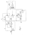
- the electronic circuit of Type I comprises a bandpass filter circuit A with its transfer function being an integral circuit B with its transfer function being a differential circuit C with its transfer function being and an additor circuit D.
- the filter circuit A is used to transfer the voltage deviation ⁇ V into the angular frequency deviation ⁇ ⁇ while the integral circuit B and the differential circuit C are used to transfer the angular frequency deviation ⁇ respectively into the power angle deviation ⁇ and the power deviation ⁇ p,
- the electronic circuit of Type II comprises a bandpass filter circuit A with its transfer function being which has an integral circuit B with its transfer function being , a seperate differential circuit C with its transfer function being , and a seperate additor circuit D.
- the filter circuit A is used to transfer the voltage deviation ⁇ V into the angular frequency deviation ⁇ , and meanwhile through its integral circuit B to get the deviation ⁇ .
- the differential circuit C is used to transfer ⁇ into the _power deviation A p. After their coefficients are respectively regulated by corresponding potentialmenters, the three deviations, ⁇ , ⁇ , and ⁇ are added by the additor circuit D.
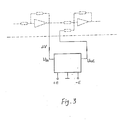
- Both Type I and II analogous circuits of simulating state variable stabilizers shown in line in Fig. 3 can be connected to every amplifier block of the original excitation system shown in dotted line in Fig. 3, thus being able to depress the low frequency oscillation of power systems. In this way, the adjustment of the original circuit can be maintained unchanged and the effect of the gain of ⁇ V can be considered in the coefficients of ⁇ , AS and ⁇ .
- the present device was put into a trial operation in a hydropower plant of a capacity of 965 MW.
- the present device Under the use of two 141.4 MVA generators having fast excitation control thyristor systems, two transformers of 150 MVA, and a transmission line of 220KV, the present device underwent an on-the-spot test by connecting the two generator- transformer sets to the system by the same bus through one transmission line. The test result was completely the same with that obtained in the dynamic analogous laboratory.
- the two generators generated 225MW, of which 190MW was sent to the system while 35MW was local load, the local load was cut off suddenly and the waves of power in the transmission line is recorded.
- the alternative components of power that periodical changes every second will diverge at a time constant of 14 seconds, yet, with the use of the present device, the alternative components will converge at a time constant of 2.8 seconds.
Landscapes
- Engineering & Computer Science (AREA)
- Power Engineering (AREA)
- Control Of Eletrric Generators (AREA)
- Supply And Distribution Of Alternating Current (AREA)
Abstract
Description
- The present invention relates to an automatic device which can be used to depress the low frequency oscillation of a power system.
- Fast excitation systems and regulators have been widely used on generators of power system to improve the operating quality and enlarge the output capability in remote power transmission. However since thyristors and other fast excitation control systems came into use, low frequency oscillation, which can affect the whole power system, might occur when the power angle of the generator reaches about 60 degree, thus becoming a technical problem of power system that needs to be solved.
- In prior art, power system stabilizers (PSS) and optimal control excitation were used to depress the low frequency oscillation. If merely the measuring of voltage deviation is taken, the control effects of both measures would not be satisfactory and it is hard to depress the low frequency oscillation. Therefore, other variables that could reflect the state of steady must be measured and used as additional feedback regulating variables. Generally speaking, the effect of PSS was not satisfactory while the optimal control was too complicated to realize, and both had the defects of difficult realization, distortions, low reliability, complicate and heavy measuring devices, etc.
- There are many literatures and patents concerning the method of depressing the low frequency oscillation of power system, such as: USSR Patent No. 546057, No. 410514, No. 468333, No. 449419, No. 546057, No. 658653, but none of them relate to the solution like that in the present invention.
- In view of above mentioned incapability of prior methods in depressing the low frequency oscillation of power system, the present invention proposes a kind of simple, reliable electronic circuit which can realize the optimal control almost as theroretical demand, depress the low frequency oscillation, and raise the output of generator even to its limit while maintaining its stability.
- The present invention is characterized in that the full state optimal control is realized to depress the low frequency oscillation by using a certain state variable, e.g. the voltage deviation instead of using the complicate direct measurement of additional feedback. The state variable here means the deviation between instantaneous value of a certain parameter and its final state value e.g. ΔV= Vit) ― V(∞) .All of the state variables needed to realize optimal control comes from an analogous electronic circuit with voltage deviation Δ V being its input and the simulating state variables needed being its outputs. Incorporating the analogous electronic circuit of the present invention in the amplifier block of the original excitation control system will depress low frequency oscillation of power systems.
-
- Fig. 1 is type I analogous electronic circuit of simulating state variables.
- Fig. 2 is type II analogous electronic circuit of simulating state variables.
- Fig. 3 is an example showing how the analogous electronic circuit is connected to an original excitation device.
- The electronic circuit of Type I comprises a bandpass filter circuit A with its transfer function being


- After their coefficients are respectively regulated by corresponding potentialmeters, the three deviations will be added by the additor circuit D.
- The electronic circuit of Type II comprises a bandpass filter circuit A with its transfer function being


- The filter circuits in the electronic circuits of Type I and II, wherein the characteristic angular frequency ωo is 1.5--2.5 times as big as the original angular frequency of low frequency oscillation ω1, and its quality factor Q being more than 5.
- Both Type I and II analogous circuits of simulating state variable stabilizers shown in line in Fig. 3 can be connected to every amplifier block of the original excitation system shown in dotted line in Fig. 3, thus being able to depress the low frequency oscillation of power systems. In this way, the adjustment of the original circuit can be maintained unchanged and the effect of the gain of ΔV can be considered in the coefficients of Δω, AS and Δρ.
- After the present device was tested for more than hundreds of times in a dynamic analogous laboratory of power system according to the paramaters in Fig. 1 and Fig. 2, it has been proved that in the system of two-generator to infinite system, without using the present device, the operation power angle can reach about 60°, causing the low frequency oscillation; however, with the employment of the present device, the operation power angle can be enlarged to about 110° and the output power can be almost doubled..
- The present device was put into a trial operation in a hydropower plant of a capacity of 965 MW. With the use of two 141.4 MVA generators having fast excitation control thyristor systems, two transformers of 150 MVA, and a transmission line of 220KV, the present device underwent an on-the-spot test by connecting the two generator- transformer sets to the system by the same bus through one transmission line. The test result was completely the same with that obtained in the dynamic analogous laboratory. When the two generators generated 225MW, of which 190MW was sent to the system while 35MW was local load, the local load was cut off suddenly and the waves of power in the transmission line is recorded. In this case, without the use of the present device, the alternative components of power that periodical changes every second will diverge at a time constant of 14 seconds, yet, with the use of the present device, the alternative components will converge at a time constant of 2.8 seconds.
- During the test and the trial operation, the present device was compared with P.S.S.device.
- The present invention has the following advantages:
- 1.- The random disturbance effect is reduced and the quality of the power in normal operation is improved.
- 2. The present device is high in adaptability for when the operation mode is changed, it does not need to change its parameters while in the same case the parameters of a P.S.S.device have to be changed.
- 3. No additional over-voltage occurs when load is suddenly cutoff.
- 4. The cooperation between multi-generators is fine.
- 5. Since the connection is very simple, the present device does not suffer any electro-magnetic disturbance, thus reliable in operation.
Claims (14)
Applications Claiming Priority (2)
| Application Number | Priority Date | Filing Date | Title |
|---|---|---|---|
| CN85103037 | 1985-04-18 | ||
| CN198585103037A CN85103037B (en) | 1985-04-18 | 1985-04-18 | Electric power system stabilizer designing for optical controlling simulated state quantities |
Publications (2)
| Publication Number | Publication Date |
|---|---|
| EP0199695A2 true EP0199695A2 (en) | 1986-10-29 |
| EP0199695A3 EP0199695A3 (en) | 1988-03-16 |
Family
ID=4792937
Family Applications (1)
| Application Number | Title | Priority Date | Filing Date |
|---|---|---|---|
| EP86850138A Withdrawn EP0199695A3 (en) | 1985-04-18 | 1986-04-17 | Optimal control power system stabilizer using simulating state variables |
Country Status (4)
| Country | Link |
|---|---|
| US (1) | US4701689A (en) |
| EP (1) | EP0199695A3 (en) |
| JP (1) | JPS61280715A (en) |
| CN (1) | CN85103037B (en) |
Cited By (2)
| Publication number | Priority date | Publication date | Assignee | Title |
|---|---|---|---|---|
| EP0456521A1 (en) * | 1990-05-11 | 1991-11-13 | Kabushiki Kaisha Toshiba | Power system control apparatus |
| EP0713287A1 (en) * | 1994-11-15 | 1996-05-22 | Kabushiki Kaisha Toshiba | Power system stabilizer for generator |
Families Citing this family (16)
| Publication number | Priority date | Publication date | Assignee | Title |
|---|---|---|---|---|
| JPH07108063B2 (en) * | 1986-01-06 | 1995-11-15 | 中部電力株式会社 | System stabilizer |
| EP0268160A1 (en) * | 1986-11-17 | 1988-05-25 | GebràDer Sulzer Aktiengesellschaft | Method and device to reduce at least one frequence portion of a periodic pulsation |
| US4855664A (en) * | 1988-06-10 | 1989-08-08 | General Electric Company | Method and apparatus for damping oscillations of an ac generator |
| US4999564A (en) * | 1989-10-12 | 1991-03-12 | General Electric Company | Power system stabilizer system having improved integrity checking scheme |
| US5216621A (en) * | 1991-02-28 | 1993-06-01 | Mehta Tech. Inc. | Line disturbance monitor and recorder system |
| US5227713A (en) * | 1991-08-08 | 1993-07-13 | Electric Power Research Institute | Vernier control system for subsynchronous resonance mitigation |
| US5483147A (en) * | 1992-07-10 | 1996-01-09 | Massachusetts Institute Of Technology | Decentralized excitation control for an electrical power utility system |
| US5440935A (en) * | 1993-03-18 | 1995-08-15 | Mts Systems Corporation | Apparatus for combining transducer output signals |
| US5703791A (en) * | 1994-02-17 | 1997-12-30 | Hitachi, Ltd. | Electric power system stabilization control apparatus and method thereof |
| JP4034397B2 (en) * | 1998-01-13 | 2008-01-16 | 中部電力株式会社 | System stabilization device |
| JP3558919B2 (en) * | 1999-04-14 | 2004-08-25 | 三菱電機株式会社 | Excitation control device and excitation control method |
| JP4073776B2 (en) * | 2002-12-19 | 2008-04-09 | 三菱電機株式会社 | Excitation control device |
| US8340931B2 (en) * | 2009-10-05 | 2012-12-25 | Mehta Tech, Inc. | Power grid with comparison of differences in remote phasor changes |
| CN103051265A (en) * | 2012-12-26 | 2013-04-17 | 浙江大学 | Power generator forced excitation control method under condition of power system faults |
| CN104951900B (en) * | 2015-06-30 | 2018-08-31 | 贵州电力试验研究院 | A kind of capability evaluating device of power system stabilizer, PSS |
| CN110266047B (en) * | 2019-07-04 | 2021-01-15 | 华中科技大学 | Wind power generation device stabilizer based on adaptive filter and control method |
Citations (4)
| Publication number | Priority date | Publication date | Assignee | Title |
|---|---|---|---|---|
| CH401222A (en) * | 1962-07-31 | 1965-10-31 | Siemens Ag | Device for controlling synchronous machines, in particular turbo-generators excited by rectifiers with a PD or PID rotor angle controller |
| US4080559A (en) * | 1976-11-15 | 1978-03-21 | General Electric Company | Torsional protective device for power system stabilizer |
| EP0078558A1 (en) * | 1981-11-03 | 1983-05-11 | BBC Aktiengesellschaft Brown, Boveri & Cie. | Method and device for stabilizing the voltage control of electrical generators |
| US4412171A (en) * | 1980-07-11 | 1983-10-25 | Siemens Aktiengesellschaft | Circuit arrangement for damping power oscillations of synchronous generators in networks |
Family Cites Families (5)
| Publication number | Priority date | Publication date | Assignee | Title |
|---|---|---|---|---|
| US1376400A (en) * | 1917-02-13 | 1921-05-03 | Westinghouse Electric & Mfg Co | Means for eliminating distorted harmonics from alternating-current generators |
| US3916291A (en) * | 1973-08-30 | 1975-10-28 | Westinghouse Electric Corp | Power generating arrangement employing synchronous dynamoelectric machine having improved dynamic and transient stability |
| JPS53103111A (en) * | 1977-02-18 | 1978-09-08 | Hitachi Ltd | Generator excitation controller |
| JPS5574400A (en) * | 1978-11-30 | 1980-06-04 | Toshiba Corp | System stabilizer |
| SE445004B (en) * | 1979-06-06 | 1986-05-20 | Asea Ab | DEVICE FOR DIMENSION OF MECHANICAL TORSION VOLTAGES BY AN ELECTRIC AC POWER GENERATOR |
-
1985
- 1985-04-18 CN CN198585103037A patent/CN85103037B/en not_active Expired
-
1986
- 1986-04-04 US US06/848,715 patent/US4701689A/en not_active Expired - Fee Related
- 1986-04-17 JP JP61089169A patent/JPS61280715A/en active Pending
- 1986-04-17 EP EP86850138A patent/EP0199695A3/en not_active Withdrawn
Patent Citations (4)
| Publication number | Priority date | Publication date | Assignee | Title |
|---|---|---|---|---|
| CH401222A (en) * | 1962-07-31 | 1965-10-31 | Siemens Ag | Device for controlling synchronous machines, in particular turbo-generators excited by rectifiers with a PD or PID rotor angle controller |
| US4080559A (en) * | 1976-11-15 | 1978-03-21 | General Electric Company | Torsional protective device for power system stabilizer |
| US4412171A (en) * | 1980-07-11 | 1983-10-25 | Siemens Aktiengesellschaft | Circuit arrangement for damping power oscillations of synchronous generators in networks |
| EP0078558A1 (en) * | 1981-11-03 | 1983-05-11 | BBC Aktiengesellschaft Brown, Boveri & Cie. | Method and device for stabilizing the voltage control of electrical generators |
Cited By (4)
| Publication number | Priority date | Publication date | Assignee | Title |
|---|---|---|---|---|
| EP0456521A1 (en) * | 1990-05-11 | 1991-11-13 | Kabushiki Kaisha Toshiba | Power system control apparatus |
| US5300876A (en) * | 1990-05-11 | 1994-04-05 | Kabushiki Kaisha Toshiba | Power system stabilizer estimating a power system impedance |
| EP0713287A1 (en) * | 1994-11-15 | 1996-05-22 | Kabushiki Kaisha Toshiba | Power system stabilizer for generator |
| US5698968A (en) * | 1994-11-15 | 1997-12-16 | Kabushiki Kaisha Toshiba | Power system stabilizer for generator |
Also Published As
| Publication number | Publication date |
|---|---|
| JPS61280715A (en) | 1986-12-11 |
| US4701689A (en) | 1987-10-20 |
| CN85103037B (en) | 1987-04-22 |
| CN85103037A (en) | 1985-12-20 |
| EP0199695A3 (en) | 1988-03-16 |
Similar Documents
| Publication | Publication Date | Title |
|---|---|---|
| EP0199695A2 (en) | Optimal control power system stabilizer using simulating state variables | |
| Cresap et al. | Small-signal modulation of the Pacific HVDC intertie | |
| Larsen et al. | Applying power system stabilizers part I: general concepts | |
| US7087332B2 (en) | Power slope targeting for DC generators | |
| US6429546B1 (en) | Systems and methods for preventing islanding of grid-connected electrical power systems | |
| DE2701495C2 (en) | Electronic voltage control device for three-phase generators | |
| Watson et al. | Experience with supplementary damping signals for generator static excitation systems | |
| Balanathan et al. | Undervoltage load shedding to avoid voltage instability | |
| De Mello et al. | Voltage oscillatory instability caused by induction motor loads | |
| CN106300342A (en) | A kind of isolated island micro-capacitance sensor operation method based on fuzzy PI hybrid control | |
| US4451777A (en) | Static VAR generation for transmission line compensation | |
| CN115356582A (en) | Dynamic aging system of photovoltaic inverter | |
| JPS5833930A (en) | Stationary reactive power compensating method | |
| US1948372A (en) | Regulating system | |
| Eberly et al. | Minimum/maximum excitation limiter performance goals for small generation | |
| Gerhart et al. | Power system stabilizer: field testing and digital simulation | |
| Larsen et al. | Control design for SVC's on the Mead-Adelanto and Mead-Phoenix transmission project | |
| Hiskens et al. | SVC behaviour under voltage collapse conditions | |
| Dandeno | General overview of steady-state (small signal) stability in bulk electricity systems: a North American perspective | |
| Shamseh et al. | Active anti-islanding technique using c-hil real time simulation | |
| Machida et al. | A method of automatic frequency ratio control by a DC system | |
| CN114264874B (en) | Auxiliary device of power analyzer | |
| Machowski et al. | Simple robust adaptive control of static VAR compensator | |
| KR100298867B1 (en) | Method for enhancing the damping of the generator and stabilizing the frequency control system by using a modified PID control | |
| CN1021391C (en) | Method and apparatus for generator voltage regulation with non-linear compensation |
Legal Events
| Date | Code | Title | Description |
|---|---|---|---|
| PUAI | Public reference made under article 153(3) epc to a published international application that has entered the european phase |
Free format text: ORIGINAL CODE: 0009012 |
|
| AK | Designated contracting states |
Kind code of ref document: A2 Designated state(s): BE CH FR GB LI SE |
|
| PUAL | Search report despatched |
Free format text: ORIGINAL CODE: 0009013 |
|
| AK | Designated contracting states |
Kind code of ref document: A3 Designated state(s): BE CH FR GB LI SE |
|
| 17P | Request for examination filed |
Effective date: 19880810 |
|
| 17Q | First examination report despatched |
Effective date: 19900810 |
|
| STAA | Information on the status of an ep patent application or granted ep patent |
Free format text: STATUS: THE APPLICATION IS DEEMED TO BE WITHDRAWN |
|
| 18D | Application deemed to be withdrawn |
Effective date: 19901103 |
|
| RIN1 | Information on inventor provided before grant (corrected) |
Inventor name: FENG, YUANXI Inventor name: REN, YUANDEPARTMENT OF ELECTRIC POWER Inventor name: CHEN, XIANZHIDEPARTMENT OF ELECTRIC POWER Inventor name: HUANG, DAKE Inventor name: LI, GUOJIUDEPARTMENT OF ELECTRIC POWER Inventor name: SUN, QUANZHONG Inventor name: ZHANG, YONGLIDEPARTMENT OF ELECTRIC POWER |