EP0193457B1 - Multilens acoustic device with variable magnification and focus - Google Patents
Multilens acoustic device with variable magnification and focus Download PDFInfo
- Publication number
- EP0193457B1 EP0193457B1 EP86400354A EP86400354A EP0193457B1 EP 0193457 B1 EP0193457 B1 EP 0193457B1 EP 86400354 A EP86400354 A EP 86400354A EP 86400354 A EP86400354 A EP 86400354A EP 0193457 B1 EP0193457 B1 EP 0193457B1
- Authority
- EP
- European Patent Office
- Prior art keywords
- lenses
- lens
- acoustic
- transducer
- coupling medium
- Prior art date
- Legal status (The legal status is an assumption and is not a legal conclusion. Google has not performed a legal analysis and makes no representation as to the accuracy of the status listed.)
- Expired
Links
Images


Classifications
-
- G—PHYSICS
- G10—MUSICAL INSTRUMENTS; ACOUSTICS
- G10K—SOUND-PRODUCING DEVICES; METHODS OR DEVICES FOR PROTECTING AGAINST, OR FOR DAMPING, NOISE OR OTHER ACOUSTIC WAVES IN GENERAL; ACOUSTICS NOT OTHERWISE PROVIDED FOR
- G10K11/00—Methods or devices for transmitting, conducting or directing sound in general; Methods or devices for protecting against, or for damping, noise or other acoustic waves in general
- G10K11/18—Methods or devices for transmitting, conducting or directing sound
- G10K11/26—Sound-focusing or directing, e.g. scanning
- G10K11/30—Sound-focusing or directing, e.g. scanning using refraction, e.g. acoustic lenses
Definitions
- the invention relates to acoustic microscopy.
- Acoustic microscopy offers certain advantages over traditional optical microscopy. First of all, it allows you to explore not only the surface of a body, but also the areas close to the surface, which are not visible when the body is opaque. In addition, for transparent bodies; it allows acoustic contrasts to appear, where the optics give little information.
- the word “lens” is associated with a meniscus shape. It is different in acoustics, where the “lens” function is achieved by a diopter, that is to say by the interface between a solid and a coupling medium. However, we will keep the word “lens”, as is customary, to define the solid body which carries one or more diopters of this type.
- diopter index the relative index of the coupling medium with respect to the solid, and this index is defined by the ratio of the speed of the acoustic waves in the solid to that in the coupling medium.
- the Applicant has found that, to carry out an image or a detection throughout the volume of a sample, it is necessary to use several lenses whose depths of field make it possible to cover the entire thickness of the sample. For example, more than ten lenses would be required to test a 10 millimeter thick ceramic sample with uniform resolution.
- the depth of field and the resolution obtained in the sample material depend on the aperture angle presented by the focused beam in the coupling medium.
- this opening angle is in turn related to the size of the transducer used, and consequently to the electrical impedance thereof.
- this electrical impedance has a nominal value of 50 ohms, which is the internal impedance of the excitation generator. It is therefore necessary to have an additional degree of freedom in order to be able to make the desired depth of field and resolution compatible with this electrical impedance of 50 ohms.
- the present invention provides a solution to these problems, a solution which essentially consists of an acoustic device with several lenses, forming a probe capable of variable magnification and focal length.
- a “complex acoustic lens” comprising a frame which coaxially houses at least two acoustic lenses, and which contains an acoustic coupling medium in the interval separating these two lenses.
- the present invention uses an apparatus having a certain relationship with this anterior complex lens, it being observed that it uses it in an entirely different context.
- the prior patent recommends the use of polystyrene lenses, and a filling medium chosen from freons, silicone oils, and fluorinated hydrocarbons. These choices are based on the search for a high acoustic propagation speed, for a frequency of a few megahertz. Outside the lenses at least, the prior patent uses the most conventional coupling medium, namely water, but lenses made of the aforementioned materials do not have a high relative index with respect to water.
- the device described in the previous French patent n ° 2 241 228 cannot be used at frequencies of the order of 50 MHz or more.
- it aims to treat simultaneously all points of an image, which is very unfavorable in terms of signal / noise ratio.
- it cannot work at a wide aperture, which compromises its resolution.
- the present invention makes use of an acoustic device with several lenses having the general structure defined above, but in which the acoustic frequency can be made higher, and above all the diopters have a high relative index, the coupling medium being such that the water.
- the device is suitable for high-resolution scanning imaging applications, and in particular it is suitable for acoustic microscopy.
- a first lens consisting of a concave diopter, hollowed out at the end of a rod of a solid material such as corundum, the other end of which is provided with a transducer acoustic material made of a piezoelectric material, focuses the radiation from the transducer. This radiation then consists of a plane acoustic wave propagating in the material of the lens.
- the second lens is composed of an internal concave diopter (that is to say facing the other lens) whose object focal point is close to the image focal point of the concave diopter of the first lens, and of a concave diopter external suitable to be coupled to the sample.
- the frame is arranged to allow relative axial displacement of the two lenses, continuously-adjustable over a predetermined range. An acoustic probe with variable focal length and magnification is thus obtained.
- the lenses are made of a material, preferably monocrystalline, which has a high relative index.
- the currently preferred material is corundum.
- silica and sintered ceramics such as alumina or silicon carbide.
- said predetermined adjustment range comprises the confocal position of the two internal diopters.
- the concave diopters can be spherical or cylindrical dioptres.
- the coupling medium provided between the two lenses is preferably mercury or liquid gallium.
- the coupling medium is mercury
- for the internal dioptres, and preferably the internal faces of the frame to be coated with a layer of gold with a bonding undercoat (Chrome or Titanium for example).
- the external diopter of the second lens is advantageously provided with a quarter-wave layer, preferably made of glass, to form an adaptation with the external coupling medium (with respect to the sample) if this medium coupling is water.
- the transducer which is in particular a lithium niobate transducer, has an active surface such that it has a radiation resistance of approximately 50 ohms, and the characteristics of the lenses are chosen for obtain the desired beam opening while respecting this radiation resistance.
- the present invention essentially considers the use of two lenses, it goes without saying that a higher number of lenses can be provided, at least for certain applications.
- the combination of the two lenses provides an enlargement of the acoustic beam.
- the combination of two (or more) lenses provides a reduction in the acoustic beam.
- the transducer which is excited in pulses, is chosen of a type capable of delivering an acoustic wave of frequency between a few tens of megahertz and a gigahertz.
- the device is designed to deliver an acoustic beam into the external coupling medium, the opening of which can be made optimal with respect to the total angle of reflection on the sample.
- the device of the invention applies in particular to the examination, in volume, of ceramic or metallic samples.
- a thin section of the sample to be examined is placed transversely at the focal point F1, in an acoustic coupling medium with the lens L1.
- a receiving device symmetrical with the preceding one with respect to the point F1, is placed on the other side, in order to detect the acoustic waves transmitted through the sample.
- This Patent Application can also apply to the examination of thin sections of samples, but it preferably relates to the non-destructive testing of thicker samples, more precisely the high-resolution non-destructive testing of materials in their volume.
- This application is particularly interesting for metals and ceramics. The rest of the description will focus mainly on the examination of ceramic materials, which better highlight the advantages of the invention, because the low toughness of ceramic materials gives, under identical stress conditions, critical defect sizes. about a hundred times weaker than in metals (typically about 0.1 mm).
- the lenses are made of corundum, unless otherwise stated.
- the coupling medium between the lenses is mercury, while the coupling medium with the sample is mercury or water, it being observed that these two materials have similar acoustic propagation speeds.
- the coupling medium such as mercury or water
- the depth of field is defined as the distance over which the focal spot remains the same width, that is to say truly the area where the light beam remains parallel.
- the depth of field must be defined differently, because, by controlling the structure of a material, one is essentially interested in whether or not one will know how to detect the echo. Even if the echo is due to a structural element on which it is not focused, the important thing is to have been able to detect this element correctly. It therefore seems preferable to refer to a depth of acoustic efficiency, defined according to the reduction in the amplitude of the field created by the lens.
- this evaluation of the depth of effectiveness of the lens corresponds to a zone of propagation medium which can give acoustic echoes for a fixed lens geometry. Outside this zone, the conditions for phasing the echoes, at the level of the lens, are no longer sufficiently respected, the detection of faults in the medium analyzed will be difficult (echoes are only observed in certain cases) , or even impossible.
- the total reflection angle on the ceramic is approximately 7 °, under the conditions set.
- d is the equivalent depth that the wave would travel from the interface between the coupling medium MC1 and the sample EC, in the absence of the sample, while Om is the opening angle which then remains the same as before.
- d ' is the distance that the wave will actually travel taking into account the presence of the sample EC, while Oi is the opening angle modified due to the refraction.
- n m is the relative index of water with respect to the material of the sample EC.
- the resolution is then given at 6dB by where d is the focusing distance in the material.
- d is the focusing distance in the material.
- the resolution is of the order of 6 to 7 wavelengths (acoustic wavelengths in water).
- the document EP-A-150 843 proposed a first solution consisting in machining several diopters at the exit of a bar such as that of FIG. 1. Although this solution allows certain progress, it is not without also posing problems, in particular of realization and implementation, when the dioptres must have neighboring radii of curvature.
- the present invention offers another solution, the block diagram of which is illustrated in FIG. 3.
- a high frequency pulse generator G10 is connected by a directional coupler CD to the two electrodes of an ultrasonic transducer T.
- the echoes received by this transducer are transmitted by the coupler CD to an echo reception and analysis circuit noted R10 .
- this device has in common with that of FIG. 1 the fact that a lens L1 is formed of a cylindrical bar whose front face L11, flat, receives the ultrasonic transducer T. Its rear face L12 is machined like a spherical or cylindrical diopter centered in C1. The image focal point associated with this diopter L12 is at F in FIG. 3.
- the acoustic radiation from this first lens L1 is applied to a second lens L2, which is here a biconcave lens, formed of two spherical or cylindrical diopters, L21 on the inside, and L22 on the outside, facing the EC sample.
- the internal diopter L21 centered at C2, is positioned here so that its object focal point is the image focal point F of the internal diopter L12.
- the acoustic lens L2 is then crossed by a parallel acoustic beam, in other words a plane wave, which passes through the material constituting the lens L2, namely corundum.
- the combination of lenses L1 and L2 makes it possible to obtain focusing at variable distance.
- the internal diopter L12 of the first lens L1 associated with the internal diopter L21 of the second lens L2 constitutes a beam-expanding system in the application presented, which is the acoustic inspection of a sample of ceramic material. It can also be used as a beam reducer in other applications such as measuring the thickness of coatings (paints).
- the acoustic beam is substantially parallel to the axis of the system inside the lens L2, and the focusing depth is given by: where e is the thickness of the coupling medium, which can be neglected in practice. Furthermore, n denotes here the relative index of the lens L2, n m denotes the index of the coupling medium relative to the material of the sample examined.
- a lithium niobate transducer which would have the shape of Figure 1, and which should illuminate such a large pupil, would have a radiation resistance of about 2 ohms.
- the invention makes it possible to produce said pupil, while retaining the electrical impedance adaptation required for the transducer, at the usual value of 50 ohms.
- the ratio between the radii of curvature of the diopters L21 and L12 is therefore equal to 5.
- the optimization of the geometry of the device also requires that the distance between the lenses L1 and L2 be minimized, in order to reduce as far as possible the travel time of the acoustic waves inside the device. Indeed, in acoustic microscopy, as in any other imaging application, it is necessary to keep a sufficient number of points on each line of the image.
- This transit time Tp is written: where e 1 and e 2 are the thicknesses of the lenses L1 and L2 respectively, v c is the speed of propagation of the ultrasound in the corundum, the two lenses being assumed to be made of corundum in this example, ⁇ is the difference between the two lenses with respect to the confocal position, and v H is the propagation speed of the acoustic waves in the coupling medium between the lenses L1 and L2.
- Corundum has various advantages including that of offering excessively low acoustic attenuation. There is therefore no constraint on the maximum dimensions to be given to the lenses L1 and L2. And we can even operate these at frequencies much higher than 100 megahertz. On the other hand, such constraints on the dimensions may occur if the output lens L2 is made of silica or sintered alumina.
- Corundum still has the distinction of being an anisotropic material, unlike silica or sintered alumina, and it belongs to the trigonal crystallographic system.
- the acoustic wave is practically a plane wave.
- the corundum has a slightly focusing section for energy, that is to say that the diffraction is less important than expected, and that the performances are a little better than that which is given by the relationships set out above.
- A is as before the distance between the focal point of the diopter L12 of the lens L1, and that of the diopter L21 of the lens L2; d is the thickness of the exit lens, R 2 is the radius of curvature of the diopter L21, R 3 is the radius of curvature of the diopter L22, and n is the refractive index (assumed to be the same) associated with the diopters L12 , L21 and L22.
- FIG. 4 illustrates the same lenses L1 and L2 in a different relative position, where the focal point F1 of the diopter L12 is spaced from the focal point F2 of the diopter L21.
- the thick dashed line M provisionally schematizes the frame which will connect the lenses L1 and L2 to allow their relative displacement, as will be seen below.
- FIG. 9 illustrates the relationship between the focusing distance f, counted from the top of the diopter L22 of the lens L2 and the spacing A between the focal points F1 and F2, this spacing being positive when F2 is to the right of F1.
- the equivalent focal distance of the lens in water varies from 0 (focusing on the output diopter L22) to 7 cm. This corresponds to a variation in the focusing distance in a ceramic sample which goes practically from the surface of the sample up to 10 mm in depth, which solves the problem posed.
- the losses at each diopter crossing are approximately 9 dB. With mercury, they reduce to less than 1 dB. (If we switch to silica lenses, these losses would be 4.5 dB and 0.2 dB respectively).
- the better transmission which results from this choice of the coupling medium is also accompanied by a significant reduction in the amplitude of the multiple echoes in the probe.
- mercury also has the advantage of attenuating very little the acoustic waves, which allows large variations in the parameter. This does not result in a significant modification of the losses in the probe. In particular, for the above-mentioned variation from +3 to -6 mm, the losses in the probe would only vary by around 4.5 dB.
- the coupling medium MC1 between the lens L1 and the lens L2 a liquid medium, of low propagation speed, of high acoustic impedance, and having a low attenuation at the acoustic waves. It has been observed that mercury and possibly gallium meet these conditions.
- the lens L22 is mechanically adapted to the coupling medium with the sample, which is water.
- This quarter wave layer performs an anti-reflection function. It is not necessary with mercury.
- the diopter L21 is covered with a layer of a few hundred nanometers of a chromium-gold alloy, which facilitates the wetting of the mercury on its surface by the formation of an amalgam. The same is done for the inner face of the frame M22, as well as of the frame M21 (FIG. 6) which cooperates with it, and the inner diopter L12 of the lens L1.
- the lens L1 for its part, can be of the type of conventional lenses used in acoustic microscopy.
- a corundum bar is provided at one of its ends with a piezoelectric transducer, for example made of lithium niobate, provided with suitable armatures, and capable of generating a longitudinal plane wave inside the bar.
- a piezoelectric transducer for example made of lithium niobate, provided with suitable armatures, and capable of generating a longitudinal plane wave inside the bar.
- an L12 diopter is machined which is polished and rigorously centered on the axis of the corundum bar.
- the diopter 12 is also well centered on its mount M21, which moves around the mount M22 in the embodiment of FIG. 6.
- the diopter L12 is first machined, so that it is centered on the axis of the corundum cylinder L1.
- the electrode is evaporated on the L11 face of the corundum bar.
- the transducer is placed on this electrode.
- a counter electrode is then evaporated on the transducer T, taking care that this counter electrode is well centered on the axis of the corundum cylinder.
- the corundum bar is then placed in the frame M 21 or M31 so that the axis of the latter coincides with that of the cooperating frame M22 or M32 as the case may be.
- An alternative embodiment consists in machining the lens L1 once mounted in its frame M31, and in doing the same for the evaporation of the counter-electrode.
- FIGS. 8, 8A and 8B illustrate a detailed embodiment of the device of the invention, in which provision is made for a controlled leak of the coupling medium, the latter being typically mercury.
- the assembly is similar to that of FIG. 7.
- the corundum bar L1 is mounted on the frame M41, of which an external thread 410 cooperates with an internal thread 420 of an enlarged part 425 of the frame M42 of the biconcave lens L2.
- a leak exists between the M41 and M42 mounts, through one or more flats 415 of the M41 mount.
- This slot ends in the reservoir 400 formed between 425 and M41. This avoids almost all of the problems encountered with mercury, given the variable volume that will exist between the lenses L1 and L2. In particular, the presence of air bubbles, or the introduction of vibrations would be very damaging, especially for imaging applications.
- the bore 417 receives an adapter body of the transducer T, held by a transverse screw 418 (FIG. 8B).
- the larger terminal bore 419 is used to house the adapter electronics for the transducer.
Landscapes
- Physics & Mathematics (AREA)
- Engineering & Computer Science (AREA)
- Acoustics & Sound (AREA)
- Multimedia (AREA)
- Investigating Or Analyzing Materials By The Use Of Ultrasonic Waves (AREA)
- Ultra Sonic Daignosis Equipment (AREA)
- Instruments For Viewing The Inside Of Hollow Bodies (AREA)
Abstract
Description
L'invention concerne la microscopie acoustique.The invention relates to acoustic microscopy.
La microscopie acoustique offre certains avantages par rapport à la microscopie optique traditionnelle. Tout d'abord, elle permet d'explorer non seulement la surface d'un corps, mais aussi les zones proches de la surface, non visibles dès lors que le corps est opaque. De plus, pour les corps transparents; elle permet de faire apparaître des contrastes acoustiques, là où l'optique ne donne que peu d'informations.Acoustic microscopy offers certain advantages over traditional optical microscopy. First of all, it allows you to explore not only the surface of a body, but also the areas close to the surface, which are not visible when the body is opaque. In addition, for transparent bodies; it allows acoustic contrasts to appear, where the optics give little information.
Ainsi, à une fréquence acoustique l'ordre du gigahertz, on obtient une résolution spatiale acoustique comparable à celle de l'optique, et qui ouvre des horizons nouveaux, notamment en biologie.Thus, at an acoustic frequency of the order of a gigahertz, we obtain an acoustic spatial resolution comparable to that of optics, and which opens up new horizons, especially in biology.
A des fréquences un peu plus basses, de l'ordre de la centaine de mégahertz, la microscopie acoustique est susceptible de procurer un moyen de contrôle non destructif des matériaux dans leur volume. Mais cette voie est encore peu explorée à l'heure actuelle.At slightly lower frequencies, of the order of a hundred megahertz, acoustic microscopy is capable of providing a means of non-destructive testing of materials in their volume. But this path is still little explored at present.
Il convient de rappeler tout d'abord que, si l'on cherche en acoustique à raisonner comme en optique, il existe néanmoins des différences entre ces deux disciplines.It should be recalled first of all that, if one seeks in reasoning to reason as in optics, there are nevertheless differences between these two disciplines.
En optique traditionnelle, le mot «lentille» est associé à une forme en ménisque. Il en est différemment en acoustique, où la fonction «lentille» est réalisée par un dioptre, c'est-à-dire par l'interface entre un solide et un milieu de couplage. On conservera néanmoins le mot «lentille», comme il est d'usage, pour définir le corps solide qui porte un ou plusieurs dioptres de ce type.In traditional optics, the word "lens" is associated with a meniscus shape. It is different in acoustics, where the "lens" function is achieved by a diopter, that is to say by the interface between a solid and a coupling medium. However, we will keep the word “lens”, as is customary, to define the solid body which carries one or more diopters of this type.
Par ailleurs, il est habituel dans les raisonnements d'optique, de travailler sur des indices de réfraction supérieurs à l'unité. On appellera donc ici «indice du dioptre» l'indice relatif du milieu de couplage par rapport au solide, et cet indice est défini par le rapport de la vitesse des ondes acoustiques dans le solide à celle dans le milieu de couplage.Furthermore, it is usual in optical reasoning to work on refractive indices greater than unity. We will therefore call here "diopter index" the relative index of the coupling medium with respect to the solid, and this index is defined by the ratio of the speed of the acoustic waves in the solid to that in the coupling medium.
Il a été indiqué précédemment que l'usage de la microscopie acoustique à des fins de contrôle non destructif des matériaux dans leur volume est peu répandu à l'heure actuelle. Il existe en effet un préjugé, suivant lequel le franchissement du dioptre constitué par le milieu de couplage acoustique et l'échantillon à examiner crée sur le faisceau acoustique des aberrations qui l'empêchent d'at- teindre une résolution satisfaisante.It has been indicated previously that the use of acoustic microscopy for the purpose of non-destructive testing of materials in their volume is not widespread at present. There is in fact a prejudice, according to which the crossing of the diopter constituted by the acoustic coupling medium and the sample to be examined creates aberrations on the acoustic beam which prevent it from reaching a satisfactory resolution.
Le Demandeur a observé qu'en fait les «rayons» très inclinés, qui créeraient cette aberration, sont fortement atténués à la traversée de l'interface milieu de couplage/échantillon. Il est alors possible de réduire lesdites aberrations, pourvu que les aberrations dues aux lentilles elles-mêmes ne soient pas prédominantes. Ce facteur, et d'autre considérations développées plus loin, conduisent à préférer des lentilles d'indice élevé, notamment supérieur à 4.The Applicant has observed that in fact the very inclined "rays", which would create this aberration, are strongly attenuated when crossing the interface between coupling medium and sample. It is then possible to reduce said aberrations, provided that the aberrations due to the lenses themselves are not predominant. This factor, and other considerations developed below, lead to prefer lenses with a high index, in particular greater than 4.
Il a été proposé dans le document EP-A-150 843 (une demande de brevet européen telle que définie à l'article 54, paragraphe 3 de la CBE) de faire usage d'une sonde électro-acoustique focalisée, opérant autour de 100 mégahertz.It has been proposed in document EP-A-150 843 (a European patent application as defined in Article 54,
Cette Demande de brevet antérieure a mis en lumière une autre difficulté: lorsque l'on observe un échantillon à l'aide d'un faisceau acoustique focalisé (pour avoir une bonne résolution), le temps d'examen devient rapidement prohibitif si le volume de l'échantillon est important.This previous patent application highlighted another difficulty: when a sample is observed using a focused acoustic beam (to have good resolution), the examination time quickly becomes prohibitive if the volume of the sample is large.
Le Demandeur a constaté que, pour réaliser une image ou une détection dans tout le volume d'un échantillon, il est nécessaire d'utiliser plusieurs lentilles dont les profondeurs de champ permettent de couvrir la totalité de l'épaisseur de l'échantillon. Il faudrait par exemple plus de dix lentilles pour contrôler un échantillon de céramique d'épaisseur 10 millimètres avec une résolution uniforme.The Applicant has found that, to carry out an image or a detection throughout the volume of a sample, it is necessary to use several lenses whose depths of field make it possible to cover the entire thickness of the sample. For example, more than ten lenses would be required to test a 10 millimeter thick ceramic sample with uniform resolution.
Une autre difficulté intervient alors: la profondeur de champ et la résolution obtenues dans le matériau de l'échantillon dépendent de l'angle d'ouverture que présente le faisceau focalisé dans le milieu de couplage. Mais cet angle d'ouverture est à son tour en relation avec la taille du transducteur utilisé, et par conséquent avec l'impédance électrique de celui-ci. Or, il est souhaitable que cette impédance électrique ait une valeur nominale de 50 ohms, qui est l'impédance interne du générateur d'excitation. Il faut donc disposer d'un degré de liberté supplémentaire pour pouvoir rendre compatible la profondeur de champ et la résolution désirées avec cette impédance électrique de 50 ohms.Another difficulty then arises: the depth of field and the resolution obtained in the sample material depend on the aperture angle presented by the focused beam in the coupling medium. However, this opening angle is in turn related to the size of the transducer used, and consequently to the electrical impedance thereof. However, it is desirable that this electrical impedance has a nominal value of 50 ohms, which is the internal impedance of the excitation generator. It is therefore necessary to have an additional degree of freedom in order to be able to make the desired depth of field and resolution compatible with this electrical impedance of 50 ohms.
La présente invention apporte une solution à ces problèmes, solution qui consiste essentiellement en un dispositif acoustique à plusieurs lentilles, formant sonde capable de grandissement et de focale variables.The present invention provides a solution to these problems, a solution which essentially consists of an acoustic device with several lenses, forming a probe capable of variable magnification and focal length.
Par le Brevet français publié sous le n° 2 241 228, on connaît une «lentille acoustique complexe» comprenant une monture qui loge coaxialement au moins deux lentilles acoustiques, et qui contient un milieu de couplage acoustique dans l'intervalle séparant ces deux lentilles.By the French patent published under No. 2,241,228, a “complex acoustic lens” is known comprising a frame which coaxially houses at least two acoustic lenses, and which contains an acoustic coupling medium in the interval separating these two lenses.
La présente invention fait appel à un appareil possédant une certaine parenté avec cette lentille complexe antérieure, étant observé qu'elle s'en sert dans un contexte tout à fait différent.The present invention uses an apparatus having a certain relationship with this anterior complex lens, it being observed that it uses it in an entirely different context.
Tout d'abord, le Brevet antérieur préconise l'usage de lentilles en polystyrène, et d'un milieu de remplissage choisi parmi les fréons, les huiles de silicone, et les hydrocarbures fluorés. Ces choix sont fondés sur la recherche d'une vitesse de propagation acoustique élevée, pour une fréquence de quelques mégahertz. A l'extérieur des lentilles au moins, le brevet antérieur utilise le milieu de couplage le plus classique, à savoir l'eau, mais des lentilles constituées des matériaux précités ne possèdent pas un indice relatif élevé par rapport à l'eau.First, the prior patent recommends the use of polystyrene lenses, and a filling medium chosen from freons, silicone oils, and fluorinated hydrocarbons. These choices are based on the search for a high acoustic propagation speed, for a frequency of a few megahertz. Outside the lenses at least, the prior patent uses the most conventional coupling medium, namely water, but lenses made of the aforementioned materials do not have a high relative index with respect to water.
A côté de cela, le dispositif décrit dans le Brevet français antérieur n° 2 241 228 n'est pas utilisable à des fréquences de l'ordre de 50 MHz ou plus. De surcroît, il a pour but de traiter simultanément tous les points d'une image, ce qui est très défavorable en termes de rapport signal/bruit. Enfin, il ne peut travailler à grande ouverture, ce qui compromet sa résolution.Besides this, the device described in the previous French patent n ° 2 241 228 cannot be used at frequencies of the order of 50 MHz or more. In addition, it aims to treat simultaneously all points of an image, which is very unfavorable in terms of signal / noise ratio. Finally, it cannot work at a wide aperture, which compromises its resolution.
La présente invention fait appèl à un dispositif acoustique à plusieurs lentilles possédant la structure générale définie ci-dessus, mais dans lequel la fréquence acoustique peut être rendue plus haute, et surtout les dioptres présentent un indice relatif élevé, le milieu de couplage étant tel que l'eau. De plus, le dispositif est propre à des applications d'imagerie par balayage, à haute résolution, et en particulier il convient en microscopie acoustique.The present invention makes use of an acoustic device with several lenses having the general structure defined above, but in which the acoustic frequency can be made higher, and above all the diopters have a high relative index, the coupling medium being such that the water. In addition, the device is suitable for high-resolution scanning imaging applications, and in particular it is suitable for acoustic microscopy.
Selon un premier aspect de la présente invention, une première lentille, constituée d'un dioptre concave, creusé à l'extrémité d'un barreau d'un matériau solide tel que le corindon, dont l'autre extrémité est munie d'un transducteur acoustique constitué d'un matériau piézo-électrique, focalise le rayonnement du transducteur. Ce rayonnement est alors constitué d'une onde acoustique plane se propageant dans le matériau'de la lentille. La seconde lentille est composée d'un dioptre concave interne (c'est-à-dire faisant face à l'autre lentille) dont le foyer objet est voisin du foyer image du dioptre concave de la première lentille, et d'un dioptre concave externe propre à être couplé à l'échantillon. Enfin, la monture est agencée pour permettre un déplacement axial relatif des deux lentilles, continûment-réglable sur une plage prédéterminée. On obtient ainsi une sonde 'acoustique à focale et grandissement variables.According to a first aspect of the present invention, a first lens, consisting of a concave diopter, hollowed out at the end of a rod of a solid material such as corundum, the other end of which is provided with a transducer acoustic material made of a piezoelectric material, focuses the radiation from the transducer. This radiation then consists of a plane acoustic wave propagating in the material of the lens. The second lens is composed of an internal concave diopter (that is to say facing the other lens) whose object focal point is close to the image focal point of the concave diopter of the first lens, and of a concave diopter external suitable to be coupled to the sample. Finally, the frame is arranged to allow relative axial displacement of the two lenses, continuously-adjustable over a predetermined range. An acoustic probe with variable focal length and magnification is thus obtained.
Les lentilles sont faites en un matériau, de préférence monocristallin, qui possède un fort indice relatif. Le matériau actuellement préféré est le corindon.The lenses are made of a material, preferably monocrystalline, which has a high relative index. The currently preferred material is corundum.
D'autres types de matériaux peuvent également convenir, comme la silice, et les céramiques frittées telles que l'alumine ou le carbure de silicium.Other types of materials may also be suitable, such as silica, and sintered ceramics such as alumina or silicon carbide.
Très avantageusement, ladite plage prédéterminée de réglage comprend la position confocale des deux dioptres internes.Very advantageously, said predetermined adjustment range comprises the confocal position of the two internal diopters.
Les dioptres concaves peuvent être des dioptres sphériques ou cylindriques.The concave diopters can be spherical or cylindrical dioptres.
Selon un autre aspect de l'invention, le milieu de couplage prévu entre les deux lentilles est, de préférence, le mercure ou le gallium liquide.According to another aspect of the invention, the coupling medium provided between the two lenses is preferably mercury or liquid gallium.
Il est alors avantageux de prévoir, entre les deux parties en mouvement relatif de la monture, une fuite contrôlée vers un réservoir du milieu de couplage.It is then advantageous to provide, between the two parts in relative movement of the frame, a controlled leak towards a reservoir of the coupling medium.
Il est également avantageux, du moins lorsque le milieu de couplage est le mercure, que les dioptres internes, et de préférence les faces internes de la monture, soient revêtus d'une couche d'or avec une sous-couche d'accrochage (Chrome ou Titane par exemple).It is also advantageous, at least when the coupling medium is mercury, for the internal dioptres, and preferably the internal faces of the frame, to be coated with a layer of gold with a bonding undercoat (Chrome or Titanium for example).
De son côté, le dioptre externe de la seconde lentille est avantageusement muni d'une couche quart d'onde, de préférence en verre, pour former adaptation avec le milieu de couplage externe (à l'égard de l'échantillon) si ce milieu de couplage est l'eau.For its part, the external diopter of the second lens is advantageously provided with a quarter-wave layer, preferably made of glass, to form an adaptation with the external coupling medium (with respect to the sample) if this medium coupling is water.
Selon un autre aspect de l'invention, le transducteur, qui est en particulier un transducteur en niobate de lithium, a une surface active telle qu'il possède une résistance de radiation d'environ 50 ohms, et les caractéristiques des lentilles sont choisies pour obtenir l'ouverture de faisceau désirée en respectant cette résistance de radiation. Bien que la présente invention considère essentiellement l'usage de deux lentilles, il va de soi que l'on pourra prévoir un nombre de lentilles plus élevé, au moins pour certaines applications.According to another aspect of the invention, the transducer, which is in particular a lithium niobate transducer, has an active surface such that it has a radiation resistance of approximately 50 ohms, and the characteristics of the lenses are chosen for obtain the desired beam opening while respecting this radiation resistance. Although the present invention essentially considers the use of two lenses, it goes without saying that a higher number of lenses can be provided, at least for certain applications.
Dans une première famille d'applications, la combinaison des deux lentilles (ou plus) procure un agrandissement du faisceau acoustique.In a first family of applications, the combination of the two lenses (or more) provides an enlargement of the acoustic beam.
Dans une autre famille d'applications, la combinaison des deux lentilles (ou plus) procure une réduction du faisceau acoustique.In another family of applications, the combination of two (or more) lenses provides a reduction in the acoustic beam.
Selon un autre aspect de l'invention, le transducteur, qui est excité en impulsions, est choisi d'un type propre à délivrer une onde acoustique de fréquence comprise entre quelques dizaines de mégahertz et un gigahertz.According to another aspect of the invention, the transducer, which is excited in pulses, is chosen of a type capable of delivering an acoustic wave of frequency between a few tens of megahertz and a gigahertz.
Plus particulièrement encore, le dispositif est agencé pour délivrer dans le milieu de couplage externe un faisceau acoustique dont l'ouverture peut être rendue optimale par rapport à l'angle de réflexion totale sur l'échantillon.More particularly still, the device is designed to deliver an acoustic beam into the external coupling medium, the opening of which can be made optimal with respect to the total angle of reflection on the sample.
Le dispositif de l'invention s'applique en particulier à l'examen, en volume, d'échantillons céramiques ou métalliques.The device of the invention applies in particular to the examination, in volume, of ceramic or metallic samples.
D'autres caractéristiques et avantages de l'invention apparaîtront à l'examen de la description détaillée ci-après, et des dessins annexés, sur lesquels:
- - la figure 1 illustre schématiquement une sonde acoustique classique,
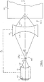
- - la figure 2 illustre schématiquement le couplage de la sonde de la figure 1 à un échantillon,
- - la figure 3 est le schéma de principe d'un dispositif selon l'invention, dans une première position relative des deux lentilles qu'il contient,
- - la figure 4 est le schéma du même dispositif dans une deuxième position relative des deux lentilles,
- - la figure 5 est un schéma du montage de la seconde lentille sur un tube,
- - les figures 6 et 7 sont deux variantes de réalisation d'un dispositif à deux lentilles selon l'invention,
- - la figure 8 est le schéma détaillé, en coupe, d'un mode de réalisation particulier de l'invention, tandis que les figures 8A et 8B sont des vues en demi-coupe de parties de la figure 8, et
- - les figures 9 à 11 sont des diagrammes servant à expliquer le fonctionnement du dispositif de l'invention.
- FIG. 1 schematically illustrates a conventional acoustic probe,
- FIG. 2 schematically illustrates the coupling of the probe of FIG. 1 to a sample,
- FIG. 3 is the block diagram of a device according to the invention, in a first relative position of the two lenses which it contains,
- FIG. 4 is the diagram of the same device in a second relative position of the two lenses,
- FIG. 5 is a diagram of the mounting of the second lens on a tube,
- FIGS. 6 and 7 are two alternative embodiments of a device with two lenses according to the invention,
- FIG. 8 is the detailed diagram, in section, of a particular embodiment of the invention, while FIGS. 8A and 8B are views in half-section of parts of FIG. 8, and
- - Figures 9 to 11 are diagrams used to explain the operation of the device of the invention.
Il a déjà été fait référence au Brevet français n° 73 30 024, publié sous le n° 2 241 228. Tout en visant spécifiquement l'examen d'organismes vivants, et l'imagerie ultrasonore associée, ce brevet antérieur paraît concerner plus généralement de nombreuses autres applications de la formation d'images et de la concentration d'ondes acoustiques. Il est à noter encore que ce brevet antérieur- permet la formation d'images relatives à des objets macroscopiques.Reference has already been made to French Patent No. 73 30,024, published under No. 2,241,228. While specifically targeting the examination of living organisms, and the associated ultrasound imaging, this prior patent appears to relate more generally many other applications of imaging and concentration of acoustic waves. It should also be noted that this prior patent- allows the formation of images relating to macroscopic objects.
Les premières propositions de microscopie acoustique ont été formulées dans les brevets Etats-Unis n° 4 012 950 et 4 028 933.The first proposals for acoustic microscopy were made in United States patents 4,012,950 and 4,028,933.
Ces brevets font usage d'une source d'ultrasons correspondant au schéma de la figure 1. Un transducteur ultrasonore T est collé sur la face arrière plane L1 d'un barreau cylindrique L1 dont la face avant est usinée pour former un dioptre L12, sphérique ou cylindrique, et centré en C1.These patents make use of an ultrasound source corresponding to the diagram in FIG. 1. An ultrasonic transducer T is bonded to the flat rear face L1 of a cylindrical bar L1 the front face of which is machined to form a diopter L12, spherical or cylindrical, and centered in C1.
Il en résulte une focalisation de l'onde acoustique plane émise par le transducteur à l'intérieur du barreau L1, en un foyer F1. La distance focale image, comptée à partir du sommet du dioptre, est donnée par la relation:![]()
![]()
Dans les brevets Etats-Unis cités, une coupe mince de l'échantillon à examiner est placée transversalement au niveau du foyer F1, dans un milieu de couplage acoustique avec la lentilb L1. Un dispositif récepteur, symétrique du précédent par rapport au point F1, est placé de l'autre côté, afin de détecter les ondes acoustiques transmises à travers l'échantillon.In the cited United States patents, a thin section of the sample to be examined is placed transversely at the focal point F1, in an acoustic coupling medium with the lens L1. A receiving device, symmetrical with the preceding one with respect to the point F1, is placed on the other side, in order to detect the acoustic waves transmitted through the sample.
Et l'excitation du transducteur T se fait en principe en ondes continues.And the excitation of the transducer T is done in principle in continuous waves.
Ces Brevets décrivent également des variantes où l'on opère en réflexion.These Patents also describe variants in which one operates in reflection.
La présente Demande de Brevet peut s'appliquer aussi à l'examen de coupes minces d'échantillons, mais elle vise préférentiellement le contrôle non destructif d'échantillons plus épais, plus exactement le contrôle non destructif à haute résolution de matériaux dans leur volume. Cette application intéresse notamment les métaux et les céramiques. La suite de la description s'attachera essentiellement à l'examen de matériaux céramiques, qui mettent mieux en lumière les avantages de l'invention, car la faible ténacité des matériaux céramiques donne, dans des conditions de sollicitation identiques, des tailles de défaut critiques environ cent fois plus faibles que dans les métaux (typiquement environ 0,1 mm).This Patent Application can also apply to the examination of thin sections of samples, but it preferably relates to the non-destructive testing of thicker samples, more precisely the high-resolution non-destructive testing of materials in their volume. This application is particularly interesting for metals and ceramics. The rest of the description will focus mainly on the examination of ceramic materials, which better highlight the advantages of the invention, because the low toughness of ceramic materials gives, under identical stress conditions, critical defect sizes. about a hundred times weaker than in metals (typically about 0.1 mm).
Dans la suite de la description, on admet aussi que les lentilles sont en corindon, sauf mention contraire. Le milieu de couplage entre les lentilles est le mercure, tandis que le milieu de couplage avec l'échantillon est le mercure ou l'eau, étant observé que ces deux matériaux possèdent des vitesses de propagation acoustiques voisines.In the following description, it is also assumed that the lenses are made of corundum, unless otherwise stated. The coupling medium between the lenses is mercury, while the coupling medium with the sample is mercury or water, it being observed that these two materials have similar acoustic propagation speeds.
Il est encore rappelé que le milieu de couplage, tel que le mercure ou l'eau, possède un indice élevé, à savoir environ 7,3, par rapport au corindon.It is also recalled that the coupling medium, such as mercury or water, has a high index, namely about 7.3, compared to corundum.
Si l'on revient maintenant à la figure 1, il a été observé que le dispositif illustré donne une tache focale pratiquement exempte d'aberrations de sphéricité, et dont le diamètre à -6dB est donné par la relation suivante:![]()
- λ est la longueur d'onde dans le milieu de focalisation.
- f est la distance focale image du dioptre déjà défini;
- et a est le diamètre de la pupille avec a = 2.R.sin 0m où Om est l'ouverture angulaire du dioptre.
- λ is the wavelength in the focusing medium.
- f is the image focal length of the diopter already defined;
- and a is the diameter of the pupil with a = 2.R.sin 0 m where O m is the angular opening of the diopter.
On sait qu'en optique lumineuse, la profondeur de champ est définie comme la distance sur laquelle la tache focale reste de même largeur, c'est-à-dire véritablement la zone où le faisceau lumineux reste parallèle.It is known that in light optics, the depth of field is defined as the distance over which the focal spot remains the same width, that is to say truly the area where the light beam remains parallel.
Le Demandeur a observé qu'en acoustique, la profondeur de champ doit être définie différemment, car, en contrôlant la structure d'un matériau, on s'intéresse essentiellement au fait que l'on va savoir ou non détecter l'écho. Même si l'écho est dû à un élément de structure sur lequel il n'est pas focalisé, l'important est d'avoir pu détecter correctement cet élément. Il apparaît donc préférable de se référer à une profondeur d'efficacité acoustique, définie d'après la diminution de l'amplitude du champ créé par la lentille.The Applicant has observed that in acoustics, the depth of field must be defined differently, because, by controlling the structure of a material, one is essentially interested in whether or not one will know how to detect the echo. Even if the echo is due to a structural element on which it is not focused, the important thing is to have been able to detect this element correctly. It therefore seems preferable to refer to a depth of acoustic efficiency, defined according to the reduction in the amplitude of the field created by the lens.
A partir de là, le Demandeur a pu observer que la profondeur d'efficacité 2p est donnée, pour une diminution de l'amplitude du champ acoustique de 6 dB par la formule:![]()
![]()
Comparativement, en optique, la profondeur de champ eût été donnée par la formule 2ï.f2/az.Comparatively, in optics, the depth of field would have been given by the formula 2.f. 2 / a z .
Il convient encore de souligner que cette évaluation de la profondeur d'efficacité de la lentille correspond à une zone de milieu de propagation pouvant donner des échos acoustiques pour une géométrie de lentille fixée. En dehors de cette zone, les conditions de mise en phase des échos, au niveau de la lentille, n'étant plus suffisamment respectées, la détection de défaut dans le milieu analysé sera difficile (on n'observe des échos que dans certains cas), voire même impossible.It should also be emphasized that this evaluation of the depth of effectiveness of the lens corresponds to a zone of propagation medium which can give acoustic echoes for a fixed lens geometry. Outside this zone, the conditions for phasing the echoes, at the level of the lens, are no longer sufficiently respected, the detection of faults in the medium analyzed will be difficult (echoes are only observed in certain cases) , or even impossible.
La profondeur d'efficacité ainsi obtenue est bien entendu limitée. Pour réaliser une image ou une détection dans tout le volume d'un échantillon, il apparaît donc nécessaire d'utiliser plusieurs lentilles dont les profondeurs d'efficacité respectives permettent de couvrir la totalité de l'épaisseur de l'échantillon. On peut ainsi établir qu'il faudrait plus de dix lentilles pour contrôler un échantillon de céramique sur une épaisseur de dix millimètres en conservant la même résolution quelle que soit la profondeur d'investigation.The depth of efficiency thus obtained is of course limited. To carry out an image or a detection throughout the volume of a sample, it therefore appears necessary to use several lenses whose respective depths of efficiency make it possible to cover the entire thickness of the sample. We can thus establish that it would take more than ten lenses to control a ceramic sample over a thickness of ten millimeters while maintaining the same resolution regardless of the depth of investigation.
En effet, l'angle de réflexion totale sur la céramique est d'environ 7°, dans les conditions fixées. Pour avoir un diamètre de tache focale mesurant environ une longueur d'onde à mi-hauteur, il est nécessaire de prendre une ouverture de lentille d'environ 5°. Cette ouverture donne, dans les céramiques, une profondeur d'efficacité à mi-hauteur qui est d'environ neuf à dix longueurs d'onde.Indeed, the total reflection angle on the ceramic is approximately 7 °, under the conditions set. To have a focal spot diameter measuring approximately a wavelength at mid-height, it is necessary to take a lens aperture of approximately 5 °. This opening gives, in ceramics, a depth of effectiveness at mid-height which is about nine to ten wavelengths.
Il est maintenant fait référence à la figure 2, où l'on note a l'ouverture du faisceau à l'entrée dans le matériau constitutif de l'échantillon EC. d est la profondeur équivalente que parcourrait l'onde à partir de l'interface entre le milieu de couplage MC1 et l'échantillon EC, en l'absence de l'échantillon, tandis que Om est l'angle d'ouverture qui reste alors le même que précédemment. d' est la distance que va parcourir effectivement l'onde compte tenu de la présence de l'échantillon EC, tandis que Oi est l'angle d'ouverture modifié du fait de la réfraction. Enfin nm est l'indice relatif de l'eau par rapport au matériau de l'échantillon EC.Reference is now made to FIG. 2, where the opening of the beam at the entry into the material constituting the sample EC is noted. d is the equivalent depth that the wave would travel from the interface between the coupling medium MC1 and the sample EC, in the absence of the sample, while Om is the opening angle which then remains the same as before. d 'is the distance that the wave will actually travel taking into account the presence of the sample EC, while Oi is the opening angle modified due to the refraction. Finally n m is the relative index of water with respect to the material of the sample EC.
On peut écrire en première approximation:![]()
![]()
![]()
![]()
![]()
![]()
Il en résulte qu'à l'angle d'ouverture initial Om = 5° correspond l'angle d'ouverture modifié Oi = 32° dans le matériau, ce qui amène 2p = 9,7 λm, où k,, est la longueur d'onde acoustique dans la céramique à la fréquence de 100 mégahertz, soit environ 0,1 millimètre. Ceci donne bien une profondeur de champ d'environ 1 mm pour chaque lentille, d'où la nécessité d'avoir une dizaine de lentilles pour couvrir la totalité de l'épaisseur d'un échantillon de 10 mm.It follows that at the initial opening angle O m = 5 ° corresponds the modified opening angle Oi = 32 ° in the material, which brings 2p = 9.7 λ m , where k ,, is the acoustic wavelength in ceramic at the frequency of 100 megahertz, or about 0.1 millimeter. This gives a depth of field of about 1 mm for each lens, hence the need to have ten or so lenses to cover the entire thickness of a 10 mm sample.
Au foyer, la résolution est alors donnée à 6dB par![]()
![]()
Dans le matériau de l'échantillon, on observe, pour un faisceau dont l'ouverture est de 5° à l'intérieur du milieu de.couplage, une résolution dans le matériau même de l'échantillon qui est de l'ordre de la longueur d'onde de propagation dans le matériau.In the material of the sample, we observe, for a beam whose opening is 5 ° inside the coupling medium, a resolution in the material of the sample which is of the order of propagation wavelength in the material.
Il va de soi que cette nécessité d'utiliser un grand nombre de lentilles pose un problème majeur à l'homme de l'art.It goes without saying that this need to use a large number of lenses poses a major problem for those skilled in the art.
Le document EP-A-150 843 a proposé une première solution consistant à usiner plusieurs dioptres à la sortie d'un barreau tel que celui de la figure 1. Bien que cette solution permette certains progrès, elle n'est pas sans poser aussi des problèmes, notamment de réalisation et de mise en oeuvre, lorsque les dioptres doivent avoir des rayons de courbure voisins.The document EP-A-150 843 proposed a first solution consisting in machining several diopters at the exit of a bar such as that of FIG. 1. Although this solution allows certain progress, it is not without also posing problems, in particular of realization and implementation, when the dioptres must have neighboring radii of curvature.
La présente invention offre une autre solution, dont le schéma de principe est illustré sur la figure 3.The present invention offers another solution, the block diagram of which is illustrated in FIG. 3.
Un générateur d'impulsions haute fréquence G10 est relié par un coupleur directif CD aux deux électrodes d'un transducteur ultrasonore T. Les échos reçus par ce transducteur sont transmis par le coupleur CD à un circuit de réception et d'analyse des échos noté R10.A high frequency pulse generator G10 is connected by a directional coupler CD to the two electrodes of an ultrasonic transducer T. The echoes received by this transducer are transmitted by the coupler CD to an echo reception and analysis circuit noted R10 .
Pour le reste, ce dispositif possède en commun avec celui de la figure 1 le fait qu'une lentille L1 est formée d'un barreau cylindrique dont la face antérieure L11, plane, reçoit le transducteur d'ultrasons T. Sa face postérieure L12 est usinée comme un dioptre sphérique ou cylindrique centré en C1. Le point de focalisation image associé à ce dioptre L12 est en F sur la figure 3.For the rest, this device has in common with that of FIG. 1 the fact that a lens L1 is formed of a cylindrical bar whose front face L11, flat, receives the ultrasonic transducer T. Its rear face L12 is machined like a spherical or cylindrical diopter centered in C1. The image focal point associated with this diopter L12 is at F in FIG. 3.
Mais au lieu d'être appliqué directement à l'échantillon, le rayonnement acoustique issu de cette première lentille L1 est appliqué à une seconde lentille L2, qui est ici une lentille biconcave, formée de deux dioptres sphériques ou cylindriques, L21 du côté intérieur, et L22 du côté extérieur, tourné vers l'échantillon EC.But instead of being applied directly to the sample, the acoustic radiation from this first lens L1 is applied to a second lens L2, which is here a biconcave lens, formed of two spherical or cylindrical diopters, L21 on the inside, and L22 on the outside, facing the EC sample.
Le dioptre interne L21, centré en C2, est positionné ici de façon que son point focal objet soit le point focal image F du dioptre interne L12. La lentille acoustique L2 est alors traversée par un faisceau acoustique parallèle, en d'autres termes une onde plane, qui transite dans le matériau constitutif de la lentille L2, à savoir du corindon.The internal diopter L21, centered at C2, is positioned here so that its object focal point is the image focal point F of the internal diopter L12. The acoustic lens L2 is then crossed by a parallel acoustic beam, in other words a plane wave, which passes through the material constituting the lens L2, namely corundum.
La combinaison des lentilles L1 et L2 permet d'obtenir une focalisation à distance variable.The combination of lenses L1 and L2 makes it possible to obtain focusing at variable distance.
On observera tout d'abord que le dioptre interne L12 de la première lentille L1, associé au dioptre interne L21 de la seconde lentille L2, constitue un système élargisseur de faisceau dans l'application présentée, qui est l'inspection acoustique d'un échantillon de matériau céramique. Il peut être également utilisé en réducteur de faisceau en d'autres applications comme la mesure d'épaisseur de revêtements (peintures).It will first be observed that the internal diopter L12 of the first lens L1, associated with the internal diopter L21 of the second lens L2, constitutes a beam-expanding system in the application presented, which is the acoustic inspection of a sample of ceramic material. It can also be used as a beam reducer in other applications such as measuring the thickness of coatings (paints).
Par ce moyen consistant à élargir ou diminuer la taille du faisceau acoustique sur la lentille L2, il devient possible de rendre compatibles les deux exigences suivantes:
- - obtenir l'ouverture de faisceau désirée sur le dioptre de sortie L22 de la seconde lentille. En l'espèce, cette ouverture est 001 = 5° environ, ce qui, pour un rayon de courbure R3 donné du dioptre L22, impose:

- - conserver une résistance de rayonnement du transducteur T qui soit proche de 50 ohms (impédance interne du générateur d'émission G10 de la figure 3), afin d'en faciliter l'adaptation d'impédance électrique.
- - obtain the desired beam opening on the output diopter L22 of the second lens. In this case, this opening is approximately 0 01 = 5 °, which, for a given radius of curvature R3 of the diopter L22, requires:
- - keep a radiation resistance of the transducer T which is close to 50 ohms (internal impedance of the emission generator G10 of FIG. 3), in order to facilitate the adaptation of electrical impedance.
On s'intéressera maintenant à la variation de focalisation que permet le dispositif de l'invention.We will now focus on the variation in focus that the device of the invention allows.
Lorsque les deux lentilles sont dans la position relative afocale, comme montré sur la figure 3, le faisceau acoustique est sensiblement parallèle à l'axe du système à l'intérieur de la lentille L2, et la profondeur de focalisation est donnée par:
Avec l'approximation consistant à négliger l'épaisseur e du milieu de couplage, on obtient:![]()
![]()
Dans le cas où la lentille L2 est en corindon, et où l'échantillon est en céramique, on a nm ≅ n - 7, ce qui donne une distance de focalisation à peu près égale à un sixième du rayon de courbure R3. En conséquence, pour une distance d'observation moyenne de 5 millimètres, il vient un rayon de courbure du dioptre de sortie L22 de valeur R3.= 30 millimètres.In the case where the lens L2 is made of corundum, and where the sample is ceramic, we have m ≅ n - 7, which gives a focusing distance roughly equal to one sixth of the radius of curvature R 3 . Consequently, for an average observation distance of 5 millimeters, there comes a radius of curvature of the output diopter L22 of value R 3. = 30 millimeters.
Pour les raisons précédemment indiquées, il convient que l'ouverture du faisceau 0m soit égale à 5° environ, afin d'obtenir dans le matériau une résolution voisine de λm = 0,1 millimètre à 100 mégahertz dans la céramique.For the reasons indicated above, the beam opening 0 m should be equal to approximately 5 °, in order to obtain in the material a resolution close to λ m = 0.1 millimeter at 100 megahertz in the ceramic.
Le diamètre du dioptre de sortie L22 est alors donné par la relation:![]()
![]()
Un transducteur en niobate de lithium qui présenterait la forme de la figure 1, et qui devrait éclairer une pupille aussi grande, présenterait une résistance de rayonnement d'environ 2 ohms. Par l'obtention d'un facteur d'expansion a = 5, l'invention permet de réaliser ladite pupille, tout en conservant l'adaptation d'impédance électrique requise pour le transducteur, à la valeur habituelle de 50 ohms.A lithium niobate transducer which would have the shape of Figure 1, and which should illuminate such a large pupil, would have a radiation resistance of about 2 ohms. By obtaining an expansion factor a = 5, the invention makes it possible to produce said pupil, while retaining the electrical impedance adaptation required for the transducer, at the usual value of 50 ohms.
Il vient maintenant:![]()
![]()
Le rapport entre les rayons de courbure des dioptres L21 et L12 est donc égal à 5.The ratio between the radii of curvature of the diopters L21 and L12 is therefore equal to 5.
Mais l'optimisation de la géométrie du dispositif demande encore que l'on minimise la distance entre les lentilles L1 et L2, afin de réduire dans toute la mesure du possible le temps de parcours des ondes acoustiques à l'intérieur du dispositif. En effet, en microscopie acoustique, comme en toute autre application d'imagerie, il faut conserver un nombre suffisant de points sur chaque ligne de l'image.However, the optimization of the geometry of the device also requires that the distance between the lenses L1 and L2 be minimized, in order to reduce as far as possible the travel time of the acoustic waves inside the device. Indeed, in acoustic microscopy, as in any other imaging application, it is necessary to keep a sufficient number of points on each line of the image.
La création d'images à l'aide du dispositif selon l'invention peut se faire de la manière décrite dans la Demande de Brevet français n° 84 01 597 déjà citée. Son contenu descriptif est à cet égard intégré à la présente demande de brevet. En bref, le balayage ligne est obtenu en faisant vibrer l'objet ou échantillon à examiner, à l'aide d'un montage du genre diapason. Le balayage d'image s'effectue à l'aide d'un déplacement micrométrique contrôlé (table motorisée) de l'échantillon.The creation of images using the device according to the invention can be done in the manner described in the French Patent Application n ° 84 01 597 already cited. Its descriptive content is in this respect integrated into the present patent application. In short, line scanning is obtained by vibrating the object or sample to be examined, using a tuning fork type assembly. The image is scanned using a controlled micrometric movement (motorized table) of the sample.
Ainsi, il a été possible de faire fonctionner un dispositif selon l'invention avec une fréquence de balayage ligne de 80 hertz. Le nombre de points sur une ligne était fixé à 512. Cela implique une fréquence de répétition des impulsions ultiasono- res au moins égale à 40 kHz, ce qui correspond à une période maximale de 25 microsecondes environ. Le temps de transit dans l'ensemble de la sonde de l'invention doit donc être bien inférieur à cette valeur. Ce temps de transit Tp s'écrit:![]()
![]()
Cette formule introduit une relation supplémentaire entre R1 et R2. Ces valeurs se trouvent alors fixées, car, comme on le verra plus loin, l'épaisseur de la lentille de sortie est imposée par la variation de la distance de focalisation qui est souhaitée en fonction de l'écartement Δ. Pour sa part, l'épaisseur de la lentille L1 est choisie de telle manière que les échos multiples donnent une périodicité égale ou supérieure à celle des échos multiples dans la lentille L2, d'où il résulte e1 supérieur ou égal à e2.This formula introduces an additional relationship between R 1 and R 2 . These values are then fixed, because, as will be seen below, the thickness of the output lens is imposed by the variation of the focusing distance which is desired as a function of the spacing Δ. For its part, the thickness of the lens L1 is chosen so that the multiple echoes give a periodicity equal to or greater than that of the multiple echoes in the lens L2, from which it results e 1 greater than or equal to e 2 .
Le corindon présente différents avantages dont celui d'offrir une atténuation acoustique excessivement faible. Il n'en résulte donc pas de contrainte sur les dimensions maximales à doner aux lentilles L1 et L2. Et l'on peut même faire fonctionner celles-ci à des fréquences beaucoup plus élevées que 100 mégahertz. Par contre, de telles contraintes sur les dimensions pourront intervenir si l'on réalise la lentille de sortie L2 en silice ou en alumine frittée.Corundum has various advantages including that of offering excessively low acoustic attenuation. There is therefore no constraint on the maximum dimensions to be given to the lenses L1 and L2. And we can even operate these at frequencies much higher than 100 megahertz. On the other hand, such constraints on the dimensions may occur if the output lens L2 is made of silica or sintered alumina.
Le corindon présente encore la particularité d'être un matériau anisotrope, contrairement à la silice ou à l'alumine frittée, et il appartient au système cristallographique trigonal. On choisit de faire propager l'onde acoustique suivant l'axe Z du système trigonal, qui est un axe de mode pur. Pour la lentille émettrice L1 l'onde acoustique est pratiquement une onde plane.Corundum still has the distinction of being an anisotropic material, unlike silica or sintered alumina, and it belongs to the trigonal crystallographic system. We choose to propagate the acoustic wave along the Z axis of the trigonal system, which is a pure mode axis. For the L1 emitting lens the acoustic wave is practically a plane wave.
Il a également été observé que, suivant son axe Z, le corindon présente une coupe légèrement focalisante pour l'énergie, c'est-à-dire que la diffraction est moins importante que prévu, et que les performances sont un peu meilleures que ce qui est donné par les relations exposées plus haut.It has also been observed that, along its Z axis, the corundum has a slightly focusing section for energy, that is to say that the diffraction is less important than expected, and that the performances are a little better than that which is given by the relationships set out above.
La situation est un peu différente dans la lentille de sortie L2. En particulier, si celle-ci est également réalisée en corindon, lorsque l'on fait varier la distance Δ entre les foyers des lentilles L1 et L2, le faisceau acoustique prend des inclinaisons importantes dans la lentille de sortie L2 par rapport à l'axe Z. L'homme de l'art comprendra que l'angle entre le vecteur d'onde et la direction de l'énergie devient alors également important. Il en résulte que la longueur focale image globale F du dispositif, exprimée dans le milieu de couplage diffère un peu de celle que l'on peut prévoir d'après la relation suivante:
Dans cette relation, A est comme précédemment la distance entre le foyer du dioptre L12 de la lentille L1, et celui du dioptre L21 de la lentille L2; d est l'épaisseur de la lentille de sortie, R2 est le rayon de courbure du dioptre L21, R3 est le rayon de courbure du dioptre L22, et n est l'indice de réfraction (supposé le même) associé aux dioptres L12, L21 et L22.In this relation, A is as before the distance between the focal point of the diopter L12 of the lens L1, and that of the diopter L21 of the lens L2; d is the thickness of the exit lens, R 2 is the radius of curvature of the diopter L21, R 3 is the radius of curvature of the diopter L22, and n is the refractive index (assumed to be the same) associated with the diopters L12 , L21 and L22.
La figure 4 illustre les mêmes lentilles L1 et L2 dans une position relative différente, où le foyer F1 du dioptre L12 est écarté du foyer F2 du dioptre L21. Il en résulte la courbure précitée de la propagation des ondes dans le matériau de la lentille L2, et le fait que la focalisation dans l'échantillon EC s'effectue plus près de l'interface entre cet échantillon EC et le milieu de couplage MC2 qui le relie à la lentille L2. Le trait tireté épais M schématise provisoirement la monture qui va relier les lentilles L1 et L2 pour permettre leur déplacement relatif, comme on le verra ci-après.FIG. 4 illustrates the same lenses L1 and L2 in a different relative position, where the focal point F1 of the diopter L12 is spaced from the focal point F2 of the diopter L21. This results in the above-mentioned curvature of the propagation of the waves in the material of the lens L2, and the fact that the focusing in the sample EC takes place closer to the interface between this sample EC and the coupling medium MC2 which connects it to the L2 lens. The thick dashed line M provisionally schematizes the frame which will connect the lenses L1 and L2 to allow their relative displacement, as will be seen below.
La figure 9 illustre la relation entre la distance de focalisation f, comptée à partir du sommet du dioptre L22 de la lentille L2 et l'écartement A entre les foyers F1 et F2, cet écartement étant positif lorsque F2 est à la droite de F1. La figure 10 fait de même pour une lentille L2 en silice, étant observé que l'on a fixé dans les deux cas les rayons de courbure de L21 et L22 respectivement à R2 = 10 mm et R3 = 30 mm. Il apparaît que, dans les deux cas, on dispose d'une zone assez large dans laquelle la variation de la distance focale f en fonction de A est sensiblement linéaire. Si l'on examine plus particulièrement la figure 9, il apparaît qu'une lentille L2 d'épaisseur 5 mm permet d'obtenir la variation de focale voulue. En particulier, pour une variation de A qui va de +3 à -6 mm, la distance focale équivalente de la lentille dans l'eau varie de 0 (focalisation sur le dioptre de sortie L22) à 7 cm. Il correspond à cela une variation de la distance de focalisation dans un échantillon céramique qui va pratiquement de la surface de l'échantillon jusqu'à 10 mm en profondeur, ce qui résoud le problème posé.FIG. 9 illustrates the relationship between the focusing distance f, counted from the top of the diopter L22 of the lens L2 and the spacing A between the focal points F1 and F2, this spacing being positive when F2 is to the right of F1. FIG. 10 does the same for a lens L2 made of silica, it being observed that in both cases the radii of curvature of L21 and L22 have been fixed at R 2 = 10 mm and R 3 = 30 mm. It appears that, in both cases, there is a fairly large area in which the variation of the focal distance f as a function of A is substantially linear. If we examine more particularly FIG. 9, it appears that a lens L2 with a thickness of 5 mm makes it possible to obtain the desired focal length variation. In particular, for a variation of A which goes from +3 to -6 mm, the equivalent focal distance of the lens in water varies from 0 (focusing on the output diopter L22) to 7 cm. This corresponds to a variation in the focusing distance in a ceramic sample which goes practically from the surface of the sample up to 10 mm in depth, which solves the problem posed.
Pour une utilisation satisfaisante du dispositif, il est nécessaire de minimiser les pertes à l'intérieur de la sonde, tout en conservant l'indice de la lentille équivalent, afin de conserver aussi une tache focale dont les dimensions sont proches de la longueur d'onde dans le matériau, pour minimiser les aberrations. Il a été observé que cette condition peut être remplie en utilisant comme milieu de couplage MC1 du mercure ou encore du gallium. Le mercure est particulièrement intéressant, en ce qu'il constitue un liquide dont la vitesse de propagation est pratiquement égale à celle de l'eau, alors que son impédance acoustique est élevée. Il en résulte une diminution considérable des pertes à la transmission dans chaque interface entre le milieu de couplage et la lentille.For a satisfactory use of the device, it is necessary to minimize the losses inside the probe, while preserving the index of the equivalent lens, in order to also preserve a focal spot whose dimensions are close to the length of wave in the material, to minimize aberrations. It has been observed that this condition can be fulfilled by using mercury or even gallium as the coupling medium MC1. Mercury is particularly advantageous in that it constitutes a liquid whose propagation speed is practically equal to that of water, while its acoustic impedance is high. This results in a considerable reduction in transmission losses in each interface between the coupling medium and the lens.
Par exemple, si on utilise des lentilles en corindon couplées avec de l'eau, les pertes à chaque franchissement de dioptre sont de 9 dB environ. Avec du mercure, elles se réduisent à moins de 1 dB. (Si l'on passe à des lentilles en silice, ces pertes seraient respectivement de 4,5 dB et 0,2 dB). La meilleure transmission qui résulte de ce choix du milieu de couplage s'accompagne également d'une diminution importante de l'amplitude des échos multiples dans la sonde.For example, if corundum lenses coupled with water are used, the losses at each diopter crossing are approximately 9 dB. With mercury, they reduce to less than 1 dB. (If we switch to silica lenses, these losses would be 4.5 dB and 0.2 dB respectively). The better transmission which results from this choice of the coupling medium is also accompanied by a significant reduction in the amplitude of the multiple echoes in the probe.
Enfin, le mercure présente également l'avantage d'atténuer très peu les ondes acoustiques, ce qui autorise de grandes variations du paramètre .- sans qu'il s'ensuive une modification notable des pertes dans la sonde. En particulier, pour la variation précitée de +3 à -6 mm, les pertes dans la sonde ne varieraient que de 4,5 dB environ.Finally, mercury also has the advantage of attenuating very little the acoustic waves, which allows large variations in the parameter. This does not result in a significant modification of the losses in the probe. In particular, for the above-mentioned variation from +3 to -6 mm, the losses in the probe would only vary by around 4.5 dB.
Il est donc important d'utiliser comme milieu de couplage MC1 entre la lentille L1 et la lentille L2 un milieu liquide, de faible vitesse de propagation, de grande impédance acoustique, et présentant une faible atténuation aux ondes acoustiques. Il a été observé que le mercure et éventuellement le gallium satisfont ces conditions.It is therefore important to use as the coupling medium MC1 between the lens L1 and the lens L2 a liquid medium, of low propagation speed, of high acoustic impedance, and having a low attenuation at the acoustic waves. It has been observed that mercury and possibly gallium meet these conditions.
Les dioptres L21 et L22 sont sphériques ou cylindriques, et de centre situé sur l'axe de la sonde Z. Alors que le centrage du dioptre L22 n'est pas excessivement critique, il est apparu que toute imprécision sur la position du centre de courbure du dioptre L21 entraîne des pertes très importantes. En effet, travaillant à 100 mégahertz, la lentille concentre dans le mercure l'énergie acoustique sur une tache focale de moins de 50 micromètres, qu'il faut recueillir à une distance n R2/(n-1) à l'aide de la lentille L2 (avec typiquement R2 = 5 à 10 mm). On prend par exemple R, = 1 mm.The diopters L21 and L22 are spherical or cylindrical, and of center located on the axis of the probe Z. While the centering of the diopter L22 is not excessively critical, it appeared that any inaccuracy on the position of the center of curvature of the diopter L21 causes very significant losses. Indeed, working at 100 megahertz, the lens concentrates in mercury the acoustic energy on a focal spot of less than 50 micrometers, which must be collected at a distance n R 2 / (n-1) using the L2 lens (with typically R 2 = 5 to 10 mm). Take for example R, = 1 mm.
Comme le montre la figure 5, la lentille L2 possédant un dioptre L21 de rayon R2 = 10 mm et un dioptre L22 de rayon R3 = 30 mm est placée dans une partie de monture M22 qui est un tube cylindrique d'acier inoxydable par exemple, de telle manière que les axes des dioptres L22 et surtout L21 soient confondus avec l'axe Z de la monture.As shown in FIG. 5, the lens L2 having a diopter L21 of radius R 2 = 10 mm and a diopter L22 of radius R 3 = 30 mm is placed in a frame part M22 which is a cylindrical tube of stainless steel by example, in such a way that the axes of the dioptres L22 and especially L21 are merged with the axis Z of the frame.
A l'aide d'une couche quart d'onde en verre déposée par évaporation, la lentille L22 est adaptée mécaniquement au milieu de couplage avec l'échantillon, qui est de l'eau. Cette couche quart d'onde réalise une fonction anti-reflet. Elle n'est pas nécessaire avec du mercure.Using a quarter-wave glass layer deposited by evaporation, the lens L22 is mechanically adapted to the coupling medium with the sample, which is water. This quarter wave layer performs an anti-reflection function. It is not necessary with mercury.
Le dioptre L21 est recouvert d'une couche de quelques centaines de nanomètres d'un alliage chrome-or, qui facilite le mouillage du mercure sur sa surface par formation d'un amalgame. On fait de même pour la face intérieure de la monture M22, ainsi que de la monture M21 (figure 6) qui coopère avec elle, et le dioptre intérieur L12 de la lentille L1.The diopter L21 is covered with a layer of a few hundred nanometers of a chromium-gold alloy, which facilitates the wetting of the mercury on its surface by the formation of an amalgam. The same is done for the inner face of the frame M22, as well as of the frame M21 (FIG. 6) which cooperates with it, and the inner diopter L12 of the lens L1.
La lentille L1, pour sa part, peut être du type des lentilles classiques utilisées en microscopie acoustique. Un barreau de corindon est muni à l'une de ses extrémités d'un transducteur piézo-électrique, par exemple en niobate de lithium, muni d'armatures convenables, et propre à engendrer une onde plane longitudinale à l'intérieur du barreau. A l'autre extrémité, on usine un dioptre L12 qui est poli, et rigoureusement centré sur l'axe du barreau de corindon. Le dioptre 12 est également bien centré sur sa monture M21, qui se déplace autour de la monture M22 dans le mode de réalisation de la figure 6.The lens L1, for its part, can be of the type of conventional lenses used in acoustic microscopy. A corundum bar is provided at one of its ends with a piezoelectric transducer, for example made of lithium niobate, provided with suitable armatures, and capable of generating a longitudinal plane wave inside the bar. At the other end, an L12 diopter is machined which is polished and rigorously centered on the axis of the corundum bar. The
On peut bien entendu concevoir un mode de réalisation inverse, comme illustré sur la figure 7, dans lequel la monture M32 associée à la lentille L2 est extérieure et sert à guider la monture M31 associée à la lentille L1.It is of course possible to conceive of a reverse embodiment, as illustrated in FIG. 7, in which the frame M32 associated with the lens L2 is external and serves to guide the frame M31 associated with the lens L1.
En pratique, on usine d'abord le dioptre L12, de façon qu'il soit centré sur l'axe du cylindre de corindon L1. On évapore l'électrode sur la face L11 du barreau de corindon. On place le transducteur sur cette électrode. On évapore alors une contre-électrode sur le transducteur T, en prenant soin que cette contre-électrode soit bien centrée sur l'axe du cylindre de corindon. Le barreau de corindon est ensuite placé dans la monture M 21 ou M31 de façon que l'axe de celle-ci soit confondu avec celui de la monture coopérante M22 ou M32 suivant le cas.In practice, the diopter L12 is first machined, so that it is centered on the axis of the corundum cylinder L1. The electrode is evaporated on the L11 face of the corundum bar. The transducer is placed on this electrode. A counter electrode is then evaporated on the transducer T, taking care that this counter electrode is well centered on the axis of the corundum cylinder. The corundum bar is then placed in the
Une variante de réalisation consiste à usiner la lentille L1 une fois montée dans sa monture M31, et à faire de même pour l'évaporation de la contre-électrode.An alternative embodiment consists in machining the lens L1 once mounted in its frame M31, and in doing the same for the evaporation of the counter-electrode.
Les expérimentations menées ont montré qu'il n'est pas souhaitable d'utiliser une lentille L1 de grande ouverture, car son faible rayon de courbure rend alors difficile et dans certains cas aléatoire l'établissement du contact acoustique avec l'autre lentille L2. De plus, compte tenu du grandissement du faisceau acoustique, il n'est pas nécessaire en fait de travailler à grande ouverture: avec les valeurs numériques précitées, une ouverture de 20° sur le dioptre L21 (ou la lentille L1 ) donne une ouverture utile 0m du faisceau de sortie (dans le milieu de couplage) qui varie de 3,5° à 9° pour une distance de focalisation allant de 12 à 70 mm.Experiments have shown that it is undesirable to use a lens L1 with a large aperture, since its small radius of curvature then makes it difficult and in certain cases uncertain to establish acoustic contact with the other lens L2. In addition, given the enlargement of the acoustic beam, it is not in fact necessary to work at a large aperture: with the aforementioned numerical values, an opening of 20 ° on the diopter L21 (or the lens L1) gives a useful opening 0 m from the output beam (in the coupling medium) which varies from 3.5 ° to 9 ° for a focusing distance ranging from 12 to 70 mm.
Les figures 8, 8A et 8B illustrent un mode de réalisation détaillé du dispositif de l'invention, dans lequel on prévoit une fuite contrôlée du milieu de couplage, celui-ci étant typiquement le mercure. Le montage est semblable à celui de la figure 7. Le barreau L1 de corindon est monté sur la monture M41, dont un filetage externe 410 coopère avec un filetage interne 420 d'une partie élargie 425 de la monture M42 de la lentille biconcave L2. Une fuite existe entre les montures M41 et M42, par un ou plusieurs méplats 415 de la monture M41. Cette fente aboutit dans le réservoir 400 ménagée entre 425 et M41. On évite ainsi la quasi-totalité des problèmes rencontrés avec le mercure, compte tenu du volume variable qui va exister entre les lentilles L1 et L2. En particulier, la présence de bulles d'air, ou l'introduction de vibrations serait très dommageable, notamment pour les applications d'imagerie.FIGS. 8, 8A and 8B illustrate a detailed embodiment of the device of the invention, in which provision is made for a controlled leak of the coupling medium, the latter being typically mercury. The assembly is similar to that of FIG. 7. The corundum bar L1 is mounted on the frame M41, of which an
L'alésage 417 reçoit un corps d'adaptation du transducteur T, maintenu par une vis transverse 418 (figure 8B). L'alésage terminal 419, plus important, sert à loger l'électronique d'adaptation du transducteur.The
Des mesures ont été réalisées pour déterminer les variations de la distance focale. Pour un échantillon d'épaisseur connue e, on a relevé l'amplitude de l'écho réfléchi sur sa face arrière (qui serait situé à droite sur les figures 3 et 4) en fonction de l'écart Δ par rapport à la position afocale des deux lentilles, tout en maintenant constante la distance entre la sonde et l'échantillon. La position du maximum d'amplitude de l'écho sur la partie arrière de l'échantillon permet de déduire la distance focale équivalente F de la lentille. Les résultats illustrés sur la figure 11 pour le corindon montrent la possibilité de focaliser un faisceau acoustique dans des échantillons céramiques d'épaisseur comprise entre 10 et 1 mm, avec le type de lentille décrit. Cette figure 11 correspond aux conditions suivantes:
- - Rayons de courbure: R, = 1 mm, R2 = 10 mm, R3 = 30 mm.
- - Ouvertures (dans le milieu de couplage, qui est du mercure) 01 = 20°, 02 = 20°, Os = 7°.
- - Lentilles L, et L2 en corindon, l'épaisseur de L2 étant 4,5 mm.
- - Bending radii: R, = 1 mm, R 2 = 10 mm, R 3 = 30 mm.
- - Openings (in the coupling medium, which is mercury) 0 1 = 20 °, 0 2 = 20 °, O s = 7 °.
- - L lenses, and L 2 in corundum, the thickness of L 2 being 4.5 mm.
Les amplitudes A (en millivolts) sont illustrées en fonction de pour des épaisseurs d'échantillon e = 10,5 mm, 5,2 mm, 3,1 mm et 0,7 mm.The amplitudes A (in millivolts) are illustrated as a function of for sample thicknesses e = 10.5 mm, 5.2 mm, 3.1 mm and 0.7 mm.
Claims (15)
Priority Applications (1)
| Application Number | Priority Date | Filing Date | Title |
|---|---|---|---|
| AT86400354T ATE45642T1 (en) | 1985-02-28 | 1986-02-19 | ACOUSTIC DEVICE WITH MULTIPLE LENSES AND ADJUSTABLE GAIN AND ADJUSTABLE FOCUS. |
Applications Claiming Priority (2)
| Application Number | Priority Date | Filing Date | Title |
|---|---|---|---|
| FR8502977A FR2578081B1 (en) | 1985-02-28 | 1985-02-28 | MULTI-LENS ACOUSTIC DEVICE WITH VARIABLE MAGNIFICATION AND FOCAL |
| FR8502977 | 1985-02-28 |
Publications (2)
| Publication Number | Publication Date |
|---|---|
| EP0193457A1 EP0193457A1 (en) | 1986-09-03 |
| EP0193457B1 true EP0193457B1 (en) | 1989-08-16 |
Family
ID=9316743
Family Applications (1)
| Application Number | Title | Priority Date | Filing Date |
|---|---|---|---|
| EP86400354A Expired EP0193457B1 (en) | 1985-02-28 | 1986-02-19 | Multilens acoustic device with variable magnification and focus |
Country Status (4)
| Country | Link |
|---|---|
| EP (1) | EP0193457B1 (en) |
| AT (1) | ATE45642T1 (en) |
| DE (1) | DE3665109D1 (en) |
| FR (1) | FR2578081B1 (en) |
Families Citing this family (2)
| Publication number | Priority date | Publication date | Assignee | Title |
|---|---|---|---|---|
| CN102264304B (en) * | 2008-10-15 | 2014-07-23 | 罗切斯特大学 | Photoacoustic imaging using versatile acoustic lens |
| CN108838747A (en) * | 2018-08-10 | 2018-11-20 | 天津大学 | A kind of focus ultrasonic fluid oscillation polishing system based on acoustic lens |
Family Cites Families (4)
| Publication number | Priority date | Publication date | Assignee | Title |
|---|---|---|---|---|
| US3934460A (en) * | 1973-08-06 | 1976-01-27 | General Electric Company | Apparatus for focusing and collimating ultrasonic waves |
| GB1498843A (en) * | 1974-03-29 | 1978-01-25 | Westinghouse Electric Corp | Acoustic camera apparatus |
| EP0131653A1 (en) * | 1983-07-19 | 1985-01-23 | N.V. Optische Industrie "De Oude Delft" | Apparatus for the non-contact disintegration of stony objects present in a body by means of sound shockwaves |
| DE3328051A1 (en) * | 1983-08-03 | 1985-02-14 | Siemens AG, 1000 Berlin und 8000 München | DEVICE FOR CONTACTLESS CRUSHING OF CONCRETE |
-
1985
- 1985-02-28 FR FR8502977A patent/FR2578081B1/en not_active Expired
-
1986
- 1986-02-19 DE DE8686400354T patent/DE3665109D1/en not_active Expired
- 1986-02-19 EP EP86400354A patent/EP0193457B1/en not_active Expired
- 1986-02-19 AT AT86400354T patent/ATE45642T1/en not_active IP Right Cessation
Also Published As
| Publication number | Publication date |
|---|---|
| FR2578081B1 (en) | 1987-05-07 |
| EP0193457A1 (en) | 1986-09-03 |
| ATE45642T1 (en) | 1989-09-15 |
| DE3665109D1 (en) | 1989-09-21 |
| FR2578081A1 (en) | 1986-08-29 |
Similar Documents
| Publication | Publication Date | Title |
|---|---|---|
| EP0385897A1 (en) | Microechographic probe using ultrasound focusing through a deformable surface | |
| US7804598B2 (en) | High power acoustic resonator with integrated optical interfacial elements | |
| EP0150779B1 (en) | Contact lens for observation and treatment of the eye with light irradiation | |
| CN103637819B (en) | Sound, light are total to the rectum optoacoustic endoscopy lens device of rotation sweep | |
| FR2783330A1 (en) | Observation apparatus for interior of body, comprises illumination source, sweeping unit, flexible fiber optic channel, and optical block adjacent to object and image presentation unit | |
| CA2251336A1 (en) | Method and system for 3-d acoustic microscopy using short pulse excitation and 3-d acoustic microscope for use therein | |
| EP0161645B1 (en) | Contact glass for ophthalmoscopy and laser beam ophthalmotherapy | |
| FR2708357A1 (en) | Acoustic microscope. | |
| WO2003056379A1 (en) | Miniaturized focusing optical head in particular for endoscope | |
| JP2019002906A (en) | Objective optical system and photoacoustic imaging apparatus | |
| EP0001532A1 (en) | Ultrasonic system for the visualisation of a narrow cross-sectional slice of a body | |
| FR2612722A1 (en) | MULTIFREQUENCY ACOUSTIC TRANSDUCER, IN PARTICULAR FOR MEDICAL IMAGING | |
| EP0193457B1 (en) | Multilens acoustic device with variable magnification and focus | |
| EP0176415B1 (en) | Acoustic microscope with aspherical lenses for the subsurface analysis of an object | |
| EP0219519B1 (en) | Non-destructive method for determining at least one point of a cracking front in a part and device for implementing such method | |
| EP0005116B1 (en) | Method of exploring an object by means of a ray | |
| EP0109886B1 (en) | Acousto-optical device for analysing spectra | |
| Ashkenazi et al. | High frequency ultrasound imaging using Fabry-Perot optical etalon | |
| Sangworasil et al. | Investigation on feasibility of using surface plasmons resonance (SPR) sensor for ultrasonic detection: A novel optical detection of ultrasonic waves | |
| FR3051562B3 (en) | ULTRASONIC STIMULATION SYSTEM OF IN VITRO SAMPLE | |
| FR2531854A1 (en) | Non-invasive instrument for measuring the mean rate of blood flow in living tissue | |
| Perez-Cota et al. | Thin-film transducers for the detection and imaging of Brillouin oscillations in transmission on cultured cells | |
| EP1472532B1 (en) | Method and device for checking tubes using ultrasound | |
| EP2361383A1 (en) | Device and method for studying a study area by means of an acoustic wave | |
| RU2603819C2 (en) | Optoacoustic lens |
Legal Events
| Date | Code | Title | Description |
|---|---|---|---|
| PUAI | Public reference made under article 153(3) epc to a published international application that has entered the european phase |
Free format text: ORIGINAL CODE: 0009012 |
|
| AK | Designated contracting states |
Kind code of ref document: A1 Designated state(s): AT BE CH DE FR GB IT LI LU NL SE |
|
| 17P | Request for examination filed |
Effective date: 19870114 |
|
| 17Q | First examination report despatched |
Effective date: 19881025 |
|
| GRAA | (expected) grant |
Free format text: ORIGINAL CODE: 0009210 |
|
| AK | Designated contracting states |
Kind code of ref document: B1 Designated state(s): AT BE CH DE FR GB IT LI LU NL SE |
|
| REF | Corresponds to: |
Ref document number: 45642 Country of ref document: AT Date of ref document: 19890915 Kind code of ref document: T |
|
| REF | Corresponds to: |
Ref document number: 3665109 Country of ref document: DE Date of ref document: 19890921 |
|
| GBT | Gb: translation of ep patent filed (gb section 77(6)(a)/1977) | ||
| ITF | It: translation for a ep patent filed |
Owner name: MODIANO & ASSOCIATI S.R.L. |
|
| PLBE | No opposition filed within time limit |
Free format text: ORIGINAL CODE: 0009261 |
|
| STAA | Information on the status of an ep patent application or granted ep patent |
Free format text: STATUS: NO OPPOSITION FILED WITHIN TIME LIMIT |
|
| 26N | No opposition filed | ||
| PGFP | Annual fee paid to national office [announced via postgrant information from national office to epo] |
Ref country code: LU Payment date: 19910122 Year of fee payment: 6 |
|
| PGFP | Annual fee paid to national office [announced via postgrant information from national office to epo] |
Ref country code: BE Payment date: 19910131 Year of fee payment: 6 |
|
| PGFP | Annual fee paid to national office [announced via postgrant information from national office to epo] |
Ref country code: SE Payment date: 19910208 Year of fee payment: 6 |
|
| PGFP | Annual fee paid to national office [announced via postgrant information from national office to epo] |
Ref country code: GB Payment date: 19910212 Year of fee payment: 6 |
|
| PGFP | Annual fee paid to national office [announced via postgrant information from national office to epo] |
Ref country code: AT Payment date: 19910214 Year of fee payment: 6 |
|
| PGFP | Annual fee paid to national office [announced via postgrant information from national office to epo] |
Ref country code: FR Payment date: 19910215 Year of fee payment: 6 |
|
| ITTA | It: last paid annual fee | ||
| PGFP | Annual fee paid to national office [announced via postgrant information from national office to epo] |
Ref country code: NL Payment date: 19910228 Year of fee payment: 6 |
|
| PGFP | Annual fee paid to national office [announced via postgrant information from national office to epo] |
Ref country code: DE Payment date: 19910326 Year of fee payment: 6 |
|
| EPTA | Lu: last paid annual fee | ||
| PGFP | Annual fee paid to national office [announced via postgrant information from national office to epo] |
Ref country code: CH Payment date: 19910513 Year of fee payment: 6 |
|
| PG25 | Lapsed in a contracting state [announced via postgrant information from national office to epo] |
Ref country code: LU Free format text: LAPSE BECAUSE OF NON-PAYMENT OF DUE FEES Effective date: 19920219 Ref country code: GB Effective date: 19920219 Ref country code: AT Effective date: 19920219 |
|
| PG25 | Lapsed in a contracting state [announced via postgrant information from national office to epo] |
Ref country code: SE Effective date: 19920220 |
|
| PG25 | Lapsed in a contracting state [announced via postgrant information from national office to epo] |
Ref country code: BE Effective date: 19920228 |
|
| PG25 | Lapsed in a contracting state [announced via postgrant information from national office to epo] |
Ref country code: LI Effective date: 19920229 Ref country code: CH Effective date: 19920229 |
|
| BERE | Be: lapsed |
Owner name: CENTRE NATIONAL DE LA RECHERCHE SCIENTIFIQUE CNRS Effective date: 19920228 |
|
| PG25 | Lapsed in a contracting state [announced via postgrant information from national office to epo] |
Ref country code: NL Effective date: 19920901 |
|
| GBPC | Gb: european patent ceased through non-payment of renewal fee | ||
| NLV4 | Nl: lapsed or anulled due to non-payment of the annual fee | ||
| PG25 | Lapsed in a contracting state [announced via postgrant information from national office to epo] |
Ref country code: FR Effective date: 19921030 |
|
| REG | Reference to a national code |
Ref country code: CH Ref legal event code: PL |
|
| PG25 | Lapsed in a contracting state [announced via postgrant information from national office to epo] |
Ref country code: DE Effective date: 19921103 |
|
| REG | Reference to a national code |
Ref country code: FR Ref legal event code: ST |
|
| EUG | Se: european patent has lapsed |
Ref document number: 86400354.6 Effective date: 19920904 |
|
| PG25 | Lapsed in a contracting state [announced via postgrant information from national office to epo] |
Ref country code: IT Free format text: LAPSE BECAUSE OF NON-PAYMENT OF DUE FEES;WARNING: LAPSES OF ITALIAN PATENTS WITH EFFECTIVE DATE BEFORE 2007 MAY HAVE OCCURRED AT ANY TIME BEFORE 2007. THE CORRECT EFFECTIVE DATE MAY BE DIFFERENT FROM THE ONE RECORDED. Effective date: 20050219 |