EP0188621B1 - Numerical control system - Google Patents
Numerical control system Download PDFInfo
- Publication number
- EP0188621B1 EP0188621B1 EP85903382A EP85903382A EP0188621B1 EP 0188621 B1 EP0188621 B1 EP 0188621B1 EP 85903382 A EP85903382 A EP 85903382A EP 85903382 A EP85903382 A EP 85903382A EP 0188621 B1 EP0188621 B1 EP 0188621B1
- Authority
- EP
- European Patent Office
- Prior art keywords
- numerical control
- section
- programmable controller
- miscellaneous
- code
- Prior art date
- Legal status (The legal status is an assumption and is not a legal conclusion. Google has not performed a legal analysis and makes no representation as to the accuracy of the status listed.)
- Expired
Links
Images


Classifications
-
- G—PHYSICS
- G05—CONTROLLING; REGULATING
- G05B—CONTROL OR REGULATING SYSTEMS IN GENERAL; FUNCTIONAL ELEMENTS OF SUCH SYSTEMS; MONITORING OR TESTING ARRANGEMENTS FOR SUCH SYSTEMS OR ELEMENTS
- G05B19/00—Programme-control systems
- G05B19/02—Programme-control systems electric
- G05B19/18—Numerical control [NC], i.e. automatically operating machines, in particular machine tools, e.g. in a manufacturing environment, so as to execute positioning, movement or co-ordinated operations by means of programme data in numerical form
- G05B19/414—Structure of the control system, e.g. common controller or multiprocessor systems, interface to servo, programmable interface controller
- G05B19/4147—Structure of the control system, e.g. common controller or multiprocessor systems, interface to servo, programmable interface controller characterised by using a programmable interface controller [PIC]
-
- G—PHYSICS
- G05—CONTROLLING; REGULATING
- G05B—CONTROL OR REGULATING SYSTEMS IN GENERAL; FUNCTIONAL ELEMENTS OF SUCH SYSTEMS; MONITORING OR TESTING ARRANGEMENTS FOR SUCH SYSTEMS OR ELEMENTS
- G05B2219/00—Program-control systems
- G05B2219/30—Nc systems
- G05B2219/35—Nc in input of data, input till input file format
- G05B2219/35252—Function, machine codes G, M
Definitions
- This invention relates to a numerical control system for controlling a machine such as a machine tool by a numerical control section and a programmable controller section. More particularly, the invention relates to a numerical control system adapted to rapidly execute processing of miscellaneous functions.
- CNC numerical control unit
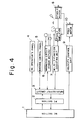
- Fig. 4 is a block diagram illustrating the general features of a numerical control system for a machine tool.
- numeral 1 denotes a numerical control (NC) section constructed about a microcomputer for outputting numerical control signals based on a machining program created by editing NC command data read in from an NC tape of a predetermined format.
- Numeral 2 designates a programmable controller (PC) section for sequentially controlling a magnetics circuit 6 of a machine tool based on a control signal produced by the NC section 1.
- the PC section is constituted by a microcomputer having a central processor, a memory for storing programs and data and the like, etc.
- Numeral 3 denotes an input/output circuit connected to a machine control panel 5, the magnetics circuit 6 and an M-, S and T-function executing unit 7. Connected to the M-, S and T-function executing unit 7 via a spindle amplifier is a spindle motor 8.
- the system is adapted to specify the number of revolutions of the machine tool spindle or the number of a tool to be changed, and to specify miscellaneous function instructions for various operations to be performed by the machine tool so that the machine tool will execute these operations.
- Numeral 9 denotes a velocity control unit for exercising control in such a manner that the velocity of a feed motor 10 will follow up a velocity command issued by the NC section 1.
- miscellaneous tasks which a machine tool carries out to perform such machining.
- these tasks include loading and unloading of workpieces, starting and stopping the spindle motor, turning a cutting oil flow on and off and selecting tools.
- These miscellaneous tasks are dealt with by the PC section 2 based on an M (miscellaneous) function instruction signal commanded by a two-digit numerical value which follows an address M outputted by the NC section 1.
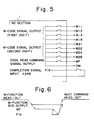
- Fig. 5 is a view for describing a machine interface for outputting miscellaneous function instruction signals read out from the NC section 1 to the PC section 2.
- M-code signals M11 through M28 specified by a BCD of two digits and a code read command signal MF are sent from the NC section 1 to the PC section 2.
- the M-code signals are decoded in the PC section 2, so that the required actuators are driven in the sequence decided in order that the commanded operaton may be performed.
- a completion signal FIN is sent to the NC section 1.
- the NC section 1 responds by turning off the code read command signal MF.
- the NC section 1 follows this by proceeding to the NC command of the next block through a sequence in which the completion signal FIN is turned off and then the M-code signal.
- FIG. 7 is an explanatory view illustrating examples of miscellaneous function instructions (hereafter referred to simply as codes) as well as functions corresponding thereto.
- codes miscellaneous function instructions
- the term "unassigned” indicates codes which allow new functions to be freely assigned and used for machine tools.
- a major topic is that a CNC so constructed shortens machining time for a single workpiece in numerical control for automatic equipment or for line use.
- the present invention makes it possible to provide a numerical control system in which a plurality of M codes may be specified in one block and the miscellaneous functions outputted to the PC section in parallel, thereby enabling the miscellaneous functions in the PC section to be rapidly executed.
- a numerical control system having a numerical control section for outputting numerical control signals based on a machining program, and a programmable controller section for executing sequential control of a machine based on the control signals from the numerical control section.
- the numerical control system is characterized by having memory means in the numerical control section for storing miscellaneous function instruction codes divided into a plurality of groups each identifiable by a respective group number; interface means in the numerical control section for outputting, to the programmable controller section, a a selected one of the miscellaneous function instruction codes as well as a code read command signal including the group number to which the selected instruction code belongs, decoding means in the programmable controller section for decoding the selected function instruction code on the basis of the code read command signal sent by the numerical control section, and miscellaneous-function executing means in the programmable controller section for executing sequential control of the machine in accordance with a plurality of decoded miscellaneous function instructions, whereby function instruction codes in different ones of said groups may be processed simultaneously by said programmable controller section.
- the present invention divides miscellaneous function instruction codes into a plurality of groups and simultaneously processes function instruction codes from different groups in parallel fashion. This makes it possible to shorten machining time and increase the amount of work performed per unit time.
- M codes (MOO - M99) shown in Fig. 7 are divided into several groups by an NC section and a control parameter for numerical control is set for each group. For example, M00 - M29 is set as group 1, M30 - M59 is set as group 2, and M60 - M99 is set as group 3.
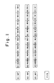
- Fig. 1 is a view for describing output signals from the NC section in a case where the M codes are divided into these three groups.
- G1, G2, G3 represent the control parameters indicative of these groups
- MF represents a code read command signal. Therefore, when G1*MF, G2"MF, G3•MF are sent to the PC section as data output signals commanding the reading of the M-code signals of groups 1 - 3, they command the decoding of the M codes.
- FIN is an input signal sent back to the NC section 1 when an operation is completed.
- Fig. 2 is a time chart indicating the output timing of the miscellaneous function instruction signals according to the present invention.
- the data output signals G1•MF, G2'MF, G3•MF of the respective groups are outputted simultaneously in parallel fashion together with the BCD output of group 1, the BCD output of group 2 and the BCD output of group 3.
- the PC section 2 decodes these M-code signals as the corresponding miscellaneous function instructions and controls the various actuators necessary for the machine tool in the sequence decided, thereby causing the machine tool to perform the operation commanded. For example, when a single machining operation is performed, it is necessary that spindle rotation, coolant and chuck loading be set. In accordance with the present invention, these miscellaneous function instructions can be processed in the PC section simultaneously in parallel fashion.
- the completion signal FIN is sent to the NC section 1, which turns off the code read command signal MF of each group.
- the NC section 1 then turns off the completion signal FIN, turns off the BCD output of each group and then proceeds to the NC command of the next block.
- the machining time of a workpiece can be shortened since various M functions can be processed simultaneously in parallel.
- the M-code instructions are composed of four bits for each digit, for a total of eight bits.
- the higher order digit need not be composed of four bits, thus making it possible to further reduce the number of bits in the M-code signal.
- a BCD code of six bits (two bits for the higher order digit + four bits for the lower order digit) will suffice if the system configuration adopted for the divided miscellaneous function instructions is such that correspondence is established between M00 - M29 and the BCD codes of 00 - 29 of group 1, between M30 - M59 and the BCD codes of 00 - 29 of group 2, and between M60 - M99 and the BCD codes of 00 - 39 of group 3, as illustrated in Fig. 3.
- the type of machining performed by the machine tool is taken into consideration and grouping suitable for executing the miscellaneous function instructions in parallel is performed anew. This readily frees the system of the present invention from a restriction wherein miscellaneous function instructions belonging to the same group cannot be specified simultaneously.
- the present invention is not limited to the illustrated embodiment but obviously can be applied in a CNC of a construction in which the PC section is included in the NC main body.
- Various modifications of this kind are possible in accordance with the gist of the present invention and are within the scope of the invention.
- the numerical control system makes it possible to process a plurality of miscellaneous function instructions simultaneously in parallel fashion and therefore is well-suited for use in the numerical control of a machine tool that requires execution of plural miscellaneous functions when performing a single machining operation.
Abstract
Description
- This invention relates to a numerical control system for controlling a machine such as a machine tool by a numerical control section and a programmable controller section. More particularly, the invention relates to a numerical control system adapted to rapidly execute processing of miscellaneous functions.
- Machines controlled by a numerical control unit (CNC) having an internal microcomputer are becoming more popular and great strides are being made in automation and conservation of energy in the machining field.
- Fig. 4 is a block diagram illustrating the general features of a numerical control system for a machine tool. In the Figure,
numeral 1 denotes a numerical control (NC) section constructed about a microcomputer for outputting numerical control signals based on a machining program created by editing NC command data read in from an NC tape of a predetermined format. Numeral 2 designates a programmable controller (PC) section for sequentially controlling amagnetics circuit 6 of a machine tool based on a control signal produced by theNC section 1. The PC section is constituted by a microcomputer having a central processor, a memory for storing programs and data and the like, etc. Numeral 3 denotes an input/output circuit connected to amachine control panel 5, themagnetics circuit 6 and an M-, S and T-function executing unit 7. Connected to the M-, S and T-function executing unit 7 via a spindle amplifier is aspindle motor 8. The system is adapted to specify the number of revolutions of the machine tool spindle or the number of a tool to be changed, and to specify miscellaneous function instructions for various operations to be performed by the machine tool so that the machine tool will execute these operations. Numeral 9 denotes a velocity control unit for exercising control in such a manner that the velocity of afeed motor 10 will follow up a velocity command issued by theNC section 1. - Though the primary task of a machine tool is machining such as cutting and turning, there are many miscellaneous tasks which a machine tool carries out to perform such machining. For instance, these tasks include loading and unloading of workpieces, starting and stopping the spindle motor, turning a cutting oil flow on and off and selecting tools. These miscellaneous tasks are dealt with by the
PC section 2 based on an M (miscellaneous) function instruction signal commanded by a two-digit numerical value which follows an address M outputted by theNC section 1. - Fig. 5 is a view for describing a machine interface for outputting miscellaneous function instruction signals read out from the
NC section 1 to thePC section 2. M-code signals M11 through M28 specified by a BCD of two digits and a code read command signal MF are sent from theNC section 1 to thePC section 2. The M-code signals are decoded in thePC section 2, so that the required actuators are driven in the sequence decided in order that the commanded operaton may be performed. When the operation is completed, a completion signal FIN is sent to theNC section 1. TheNC section 1 responds by turning off the code read command signal MF. TheNC section 1 follows this by proceeding to the NC command of the next block through a sequence in which the completion signal FIN is turned off and then the M-code signal. - A time chart for this operation is shown in Fig. 6. Fig. 7 is an explanatory view illustrating examples of miscellaneous function instructions (hereafter referred to simply as codes) as well as functions corresponding thereto. The term "unassigned" indicates codes which allow new functions to be freely assigned and used for machine tools.
- A major topic is that a CNC so constructed shortens machining time for a single workpiece in numerical control for automatic equipment or for line use.
- In a conventional numerical control system, however, even if an M-function word specifies two or more M codes in one block of a machining program, only the last M code is treated as being effective. With a CNC of this type, only one M-function can be specified in the one block following the sequence number of the conventional NC tape format. Accordingly, the prescribed machining of a workpiece begins after all of the necessary miscellaneous functions have been set in the PC section upon being read out of the NC section one at a time for each block. A problem that results is that machining time cannot be curtailed.
- The present invention makes it possible to provide a numerical control system in which a plurality of M codes may be specified in one block and the miscellaneous functions outputted to the PC section in parallel, thereby enabling the miscellaneous functions in the PC section to be rapidly executed.
- According to the present invention, there is provided a numerical control system having a numerical control section for outputting numerical control signals based on a machining program, and a programmable controller section for executing sequential control of a machine based on the control signals from the numerical control section. The numerical control system is characterized by having memory means in the numerical control section for storing miscellaneous function instruction codes divided into a plurality of groups each identifiable by a respective group number; interface means in the numerical control section for outputting, to the programmable controller section, a a selected one of the miscellaneous function instruction codes as well as a code read command signal including the group number to which the selected instruction code belongs, decoding means in the programmable controller section for decoding the selected function instruction code on the basis of the code read command signal sent by the numerical control section, and miscellaneous-function executing means in the programmable controller section for executing sequential control of the machine in accordance with a plurality of decoded miscellaneous function instructions, whereby function instruction codes in different ones of said groups may be processed simultaneously by said programmable controller section.
- The present invention divides miscellaneous function instruction codes into a plurality of groups and simultaneously processes function instruction codes from different groups in parallel fashion. This makes it possible to shorten machining time and increase the amount of work performed per unit time.
-
- Fig. 1 is a view for describing an exemplary arrangement of miscellaneous function instruction signals according to the present invention, Fig. 2 is a time chart indicating output timing of miscellaneous function instruction signals according to the present invention, Fig. 3 is an explanatory view illustrating another exemplary arrangement of miscellaneous function instruction signals, Fig. 4 is a block diagram illustrating a numerical control system of a machine tool, Fig. 5 is an explanatory view illustrating a machine interface for outputting miscellaneous function instruction signals, Fig. 6 is a time chart of miscellaneous function instruction signals according to the prior art, and Fig. 7 is a view for describing miscellaneous function codes and their functions.
- The present invention will now be described in detail with reference to the drawings.
- M codes (MOO - M99) shown in Fig. 7 are divided into several groups by an NC section and a control parameter for numerical control is set for each group. For example, M00 - M29 is set as
group 1, M30 - M59 is set asgroup 2, and M60 - M99 is set asgroup 3. - Fig. 1 is a view for describing output signals from the NC section in a case where the M codes are divided into these three groups. In the Figure, G1, G2, G3 represent the control parameters indicative of these groups, and MF represents a code read command signal. Therefore, when G1*MF, G2"MF, G3•MF are sent to the PC section as data output signals commanding the reading of the M-code signals of groups 1 - 3, they command the decoding of the M codes.
- Further, in Fig. 1,
- G1'M28 - G1'M11
- G2•M28-G2•M11
- G3•M28 - G3•M11
- indicate M-code signals of the groups 1 - 3. The four bits on the left side of the Figure represent a BCD code of a second digit, and the four bits on the right side represent a BCD code of a first digit.
- Accordingly, one of the M codes M00 - M29 is specified together with the data output signal G1 MF, one of the M codes M30 - M59 is specified together with the data output signal G2*MF, and one of the M codes M60 - M99 is specified together with the data output signal G3 MF. These are outputted to the PC section.
- Note that FIN is an input signal sent back to the
NC section 1 when an operation is completed. - Fig. 2 is a time chart indicating the output timing of the miscellaneous function instruction signals according to the present invention.
- The miscellaneous function instruction output operation will now be described with reference to Fig. 2.
- In accordance with the present invention, when an M-function instruction is read from a machining program by the
NC section 1, the data output signals G1•MF, G2'MF, G3•MF of the respective groups are outputted simultaneously in parallel fashion together with the BCD output ofgroup 1, the BCD output ofgroup 2 and the BCD output ofgroup 3. ThePC section 2 decodes these M-code signals as the corresponding miscellaneous function instructions and controls the various actuators necessary for the machine tool in the sequence decided, thereby causing the machine tool to perform the operation commanded. For example, when a single machining operation is performed, it is necessary that spindle rotation, coolant and chuck loading be set. In accordance with the present invention, these miscellaneous function instructions can be processed in the PC section simultaneously in parallel fashion. - Next, upon completion of these various operations, the completion signal FIN is sent to the
NC section 1, which turns off the code read command signal MF of each group. TheNC section 1 then turns off the completion signal FIN, turns off the BCD output of each group and then proceeds to the NC command of the next block. - Thus, according to the present invention, the machining time of a workpiece can be shortened since various M functions can be processed simultaneously in parallel.
- According to the embodiment shown in Fig. 1, the M-code instructions are composed of four bits for each digit, for a total of eight bits. However, depending upon the number of groups into which division is made, the higher order digit need not be composed of four bits, thus making it possible to further reduce the number of bits in the M-code signal.
- By way of example, a BCD code of six bits (two bits for the higher order digit + four bits for the lower order digit) will suffice if the system configuration adopted for the divided miscellaneous function instructions is such that correspondence is established between M00 - M29 and the BCD codes of 00 - 29 of
group 1, between M30 - M59 and the BCD codes of 00 - 29 ofgroup 2, and between M60 - M99 and the BCD codes of 00 - 39 ofgroup 3, as illustrated in Fig. 3. - Further, as a method of dividing the miscellaneous function instructions in a way separate from that of the above-described embodiment, the type of machining performed by the machine tool is taken into consideration and grouping suitable for executing the miscellaneous function instructions in parallel is performed anew. This readily frees the system of the present invention from a restriction wherein miscellaneous function instructions belonging to the same group cannot be specified simultaneously.
- The present invention is not limited to the illustrated embodiment but obviously can be applied in a CNC of a construction in which the PC section is included in the NC main body. Various modifications of this kind are possible in accordance with the gist of the present invention and are within the scope of the invention.
- Thus, the numerical control system according to the present invention makes it possible to process a plurality of miscellaneous function instructions simultaneously in parallel fashion and therefore is well-suited for use in the numerical control of a machine tool that requires execution of plural miscellaneous functions when performing a single machining operation.
Claims (2)
Applications Claiming Priority (2)
| Application Number | Priority Date | Filing Date | Title |
|---|---|---|---|
| JP138930/84 | 1984-07-06 | ||
| JP59138930A JPS6120104A (en) | 1984-07-06 | 1984-07-06 | Numerical control system |
Publications (3)
| Publication Number | Publication Date |
|---|---|
| EP0188621A1 EP0188621A1 (en) | 1986-07-30 |
| EP0188621A4 EP0188621A4 (en) | 1988-05-19 |
| EP0188621B1 true EP0188621B1 (en) | 1991-11-13 |
Family
ID=15233462
Family Applications (1)
| Application Number | Title | Priority Date | Filing Date |
|---|---|---|---|
| EP85903382A Expired EP0188621B1 (en) | 1984-07-06 | 1985-07-05 | Numerical control system |
Country Status (5)
| Country | Link |
|---|---|
| US (1) | US4692872A (en) |
| EP (1) | EP0188621B1 (en) |
| JP (1) | JPS6120104A (en) |
| DE (1) | DE3584671D1 (en) |
| WO (1) | WO1986000726A1 (en) |
Families Citing this family (21)
| Publication number | Priority date | Publication date | Assignee | Title |
|---|---|---|---|---|
| JPS62267804A (en) * | 1986-05-15 | 1987-11-20 | Fanuc Ltd | Nc data changing method |
| JPS63143607A (en) * | 1986-12-08 | 1988-06-15 | Matsushita Electric Ind Co Ltd | Numerical controller |
| JPH0695290B2 (en) * | 1987-02-21 | 1994-11-24 | フアナツク株式会社 | Interface method in numerical control device |
| JPS63273105A (en) * | 1987-04-30 | 1988-11-10 | Fanuc Ltd | Numerical controller |
| JPS63311405A (en) * | 1987-06-13 | 1988-12-20 | Fanuc Ltd | Command system for plural m codes of numerical controller |
| JPH0797287B2 (en) * | 1987-06-26 | 1995-10-18 | ファナック株式会社 | MST function command processing method |
| JPS6425208A (en) * | 1987-07-21 | 1989-01-27 | Fanuc Ltd | Numerical controller |
| JPS6462709A (en) * | 1987-09-02 | 1989-03-09 | Fanuc Ltd | Spindle control system |
| JP2843568B2 (en) * | 1988-04-27 | 1999-01-06 | ファナック株式会社 | Numerical control unit |
| JPH02307806A (en) * | 1989-02-10 | 1990-12-21 | Idemitsu Kosan Co Ltd | Production of surface-reformed metal oxide superfine grain |
| JPH077288B2 (en) * | 1989-03-31 | 1995-01-30 | オ−クマ株式会社 | Numerical control information creation device |
| JPH06105407B2 (en) * | 1989-04-25 | 1994-12-21 | オ−クマ株式会社 | Numerical control information creation device |
| JP2982010B2 (en) * | 1989-06-23 | 1999-11-22 | 三菱電機株式会社 | Numerical control method and device |
| DE59306252D1 (en) * | 1992-10-29 | 1997-05-28 | Siemens Ag | Method for controlling a machine tool or a robot |
| JP3631498B2 (en) * | 1997-02-19 | 2005-03-23 | 三菱電機株式会社 | Numerical control device with built-in personal computer |
| JP2001177949A (en) | 1999-12-17 | 2001-06-29 | Yazaki Corp | Structure for incorporating electronic unit in electrical junction box |
| JP3896076B2 (en) * | 2002-12-26 | 2007-03-22 | ファナック株式会社 | Numerical controller |
| US8934998B1 (en) * | 2010-09-11 | 2015-01-13 | Unist, Inc. | Method and apparatus for delivery of minimum quantity lubrication |
| US10105487B2 (en) * | 2013-01-24 | 2018-10-23 | Chrono Therapeutics Inc. | Optimized bio-synchronous bioactive agent delivery system |
| JP6276234B2 (en) * | 2015-10-15 | 2018-02-07 | ファナック株式会社 | Numerical control device with program check function by override switch |
| JP6453923B2 (en) * | 2017-02-28 | 2019-01-16 | ファナック株式会社 | Numerical control device and machine tool system |
Family Cites Families (9)
| Publication number | Priority date | Publication date | Assignee | Title |
|---|---|---|---|---|
| GB947088A (en) * | 1960-05-13 | 1964-01-22 | Kearney & Trecker Corp | Machine tool control system |
| NL7511705A (en) * | 1975-10-06 | 1977-04-12 | Philips Nv | NUMERIC CONTROLS FOR A MULTIPLE TOOL MACHINE. |
| JPS521287A (en) * | 1975-06-21 | 1977-01-07 | Fanuc Ltd | Numeric value control device |
| JPS521288A (en) * | 1975-06-24 | 1977-01-07 | Oki Electric Ind Co Ltd | Numeric value control system having performance to call program |
| JPS5427681A (en) * | 1977-07-29 | 1979-03-01 | Toyoda Mach Works Ltd | Decode circuit of code input |
| JPS5636709A (en) * | 1979-09-04 | 1981-04-10 | Fanuc Ltd | Numerical control system |
| JPS57113110A (en) * | 1980-12-30 | 1982-07-14 | Fanuc Ltd | Numeric control system |
| US4547855A (en) * | 1982-09-01 | 1985-10-15 | Westinghouse Electric Corp. | Plural computer control for shared laser machining |
| JPH113110A (en) * | 1997-06-13 | 1999-01-06 | Nkk Corp | Working data preparing method and medium storing program for the same |
-
1984
- 1984-07-06 JP JP59138930A patent/JPS6120104A/en active Pending
-
1985
- 1985-07-05 EP EP85903382A patent/EP0188621B1/en not_active Expired
- 1985-07-05 DE DE8585903382T patent/DE3584671D1/en not_active Expired - Lifetime
- 1985-07-05 WO PCT/JP1985/000380 patent/WO1986000726A1/en active IP Right Grant
- 1985-07-05 US US06/834,245 patent/US4692872A/en not_active Expired - Fee Related
Also Published As
| Publication number | Publication date |
|---|---|
| EP0188621A4 (en) | 1988-05-19 |
| DE3584671D1 (en) | 1991-12-19 |
| EP0188621A1 (en) | 1986-07-30 |
| US4692872A (en) | 1987-09-08 |
| JPS6120104A (en) | 1986-01-28 |
| WO1986000726A1 (en) | 1986-01-30 |
Similar Documents
| Publication | Publication Date | Title |
|---|---|---|
| EP0188621B1 (en) | Numerical control system | |
| EP0413921B1 (en) | Numerical controller | |
| US5127140A (en) | Numerically-controlled lathe, numerically-controlled device therefor and processing procedure thereby | |
| EP0312608B1 (en) | Numerical control device | |
| US20030187624A1 (en) | CNC control unit with learning ability for machining centers | |
| JPS5822412A (en) | Industrial robot control system | |
| US4606001A (en) | Customized canned cycles for computer numerical control system | |
| EP0521164B1 (en) | Method of restarting operation of punch press machine and numerically controlled device | |
| EP0407589B1 (en) | Nc instruction system | |
| EP0397886A1 (en) | Cnc control system | |
| US4814999A (en) | Automatic programming system | |
| JP3893334B2 (en) | Multi-system numerical controller | |
| JPH07104823A (en) | Numerically controlled working system | |
| US5359270A (en) | Numerical control system | |
| EP0328665A1 (en) | Numerical controller | |
| US5060163A (en) | Programming apparatus for lathes | |
| JP2875801B2 (en) | DNC equipment | |
| JP2584225B2 (en) | Numerical control unit | |
| EP0380685A1 (en) | Nc command system | |
| JPH05204421A (en) | Method for processing nc program | |
| EP0067879A1 (en) | Numerically controlled machining system | |
| JPH03246707A (en) | Position correcting system by systems | |
| JPS5922103A (en) | Numeric controlling method | |
| JPS59172006A (en) | Numerical controller | |
| JPH01295306A (en) | Numerical controller |
Legal Events
| Date | Code | Title | Description |
|---|---|---|---|
| PUAI | Public reference made under article 153(3) epc to a published international application that has entered the european phase |
Free format text: ORIGINAL CODE: 0009012 |
|
| 17P | Request for examination filed |
Effective date: 19860220 |
|
| AK | Designated contracting states |
Kind code of ref document: A1 Designated state(s): DE FR GB |
|
| A4 | Supplementary search report drawn up and despatched |
Effective date: 19880519 |
|
| 17Q | First examination report despatched |
Effective date: 19900620 |
|
| GRAA | (expected) grant |
Free format text: ORIGINAL CODE: 0009210 |
|
| AK | Designated contracting states |
Kind code of ref document: B1 Designated state(s): DE FR GB |
|
| REF | Corresponds to: |
Ref document number: 3584671 Country of ref document: DE Date of ref document: 19911219 |
|
| ET | Fr: translation filed | ||
| PLBE | No opposition filed within time limit |
Free format text: ORIGINAL CODE: 0009261 |
|
| STAA | Information on the status of an ep patent application or granted ep patent |
Free format text: STATUS: NO OPPOSITION FILED WITHIN TIME LIMIT |
|
| 26N | No opposition filed | ||
| PGFP | Annual fee paid to national office [announced via postgrant information from national office to epo] |
Ref country code: GB Payment date: 19930625 Year of fee payment: 9 |
|
| PGFP | Annual fee paid to national office [announced via postgrant information from national office to epo] |
Ref country code: FR Payment date: 19930709 Year of fee payment: 9 |
|
| PG25 | Lapsed in a contracting state [announced via postgrant information from national office to epo] |
Ref country code: GB Effective date: 19940705 |
|
| GBPC | Gb: european patent ceased through non-payment of renewal fee |
Effective date: 19940705 |
|
| PG25 | Lapsed in a contracting state [announced via postgrant information from national office to epo] |
Ref country code: FR Effective date: 19950331 |
|
| REG | Reference to a national code |
Ref country code: FR Ref legal event code: ST |
|
| PGFP | Annual fee paid to national office [announced via postgrant information from national office to epo] |
Ref country code: DE Payment date: 19970714 Year of fee payment: 13 |
|
| PG25 | Lapsed in a contracting state [announced via postgrant information from national office to epo] |
Ref country code: DE Free format text: LAPSE BECAUSE OF NON-PAYMENT OF DUE FEES Effective date: 19990501 |