EP0186359A2 - Containers for software - Google Patents
Containers for software Download PDFInfo
- Publication number
- EP0186359A2 EP0186359A2 EP85308919A EP85308919A EP0186359A2 EP 0186359 A2 EP0186359 A2 EP 0186359A2 EP 85308919 A EP85308919 A EP 85308919A EP 85308919 A EP85308919 A EP 85308919A EP 0186359 A2 EP0186359 A2 EP 0186359A2
- Authority
- EP
- European Patent Office
- Prior art keywords
- wall
- disc
- container according
- compartment
- diskette
- Prior art date
- Legal status (The legal status is an assumption and is not a legal conclusion. Google has not performed a legal analysis and makes no representation as to the accuracy of the status listed.)
- Withdrawn
Links
- 230000000717 retained effect Effects 0.000 claims description 3
- 230000007704 transition Effects 0.000 claims description 2
- 239000000463 material Substances 0.000 description 9
- 229920003023 plastic Polymers 0.000 description 5
- 239000004033 plastic Substances 0.000 description 5
- 230000000694 effects Effects 0.000 description 3
- 230000002459 sustained effect Effects 0.000 description 3
- 210000002105 tongue Anatomy 0.000 description 3
- 238000002347 injection Methods 0.000 description 2
- 239000007924 injection Substances 0.000 description 2
- 238000007789 sealing Methods 0.000 description 2
- 230000004308 accommodation Effects 0.000 description 1
- 230000002411 adverse Effects 0.000 description 1
- 230000003190 augmentative effect Effects 0.000 description 1
- 238000010276 construction Methods 0.000 description 1
- 210000004905 finger nail Anatomy 0.000 description 1
- 238000001746 injection moulding Methods 0.000 description 1
- 230000037431 insertion Effects 0.000 description 1
- 238000003780 insertion Methods 0.000 description 1
- 238000004519 manufacturing process Methods 0.000 description 1
- 230000002093 peripheral effect Effects 0.000 description 1
- 230000001681 protective effect Effects 0.000 description 1
Images


Classifications
-
- G—PHYSICS
- G11—INFORMATION STORAGE
- G11B—INFORMATION STORAGE BASED ON RELATIVE MOVEMENT BETWEEN RECORD CARRIER AND TRANSDUCER
- G11B23/00—Record carriers not specific to the method of recording or reproducing; Accessories, e.g. containers, specially adapted for co-operation with the recording or reproducing apparatus ; Intermediate mediums; Apparatus or processes specially adapted for their manufacture
- G11B23/02—Containers; Storing means both adapted to cooperate with the recording or reproducing means
- G11B23/023—Containers for magazines or cassettes
-
- G—PHYSICS
- G11—INFORMATION STORAGE
- G11B—INFORMATION STORAGE BASED ON RELATIVE MOVEMENT BETWEEN RECORD CARRIER AND TRANSDUCER
- G11B33/00—Constructional parts, details or accessories not provided for in the other groups of this subclass
- G11B33/02—Cabinets; Cases; Stands; Disposition of apparatus therein or thereon
- G11B33/04—Cabinets; Cases; Stands; Disposition of apparatus therein or thereon modified to store record carriers
- G11B33/0405—Cabinets; Cases; Stands; Disposition of apparatus therein or thereon modified to store record carriers for storing discs
- G11B33/0411—Single disc boxes
- G11B33/0416—Single disc boxes for disc cartridges
Definitions
- This invention relates to containers for software and more particularly to containers for accommodating and protecting floppy discs which may or may not be accompanied by one or more cassettes of magnetic tape and by instructional literature.
- floppy disc holders do not protect the discs from externally or internally applied forces which is very undesirable in view of the extremely sensitive nature of floppy discs regarding "creasing" or other physical blemishes which can adversely affect the reading of information stored on the discs. Furthermore, it has been found that floppy discs are sensitive to sustained pressure such as is occasioned, for example, when a number of discs are stacked one upon the other or when a disc is in a stack of other objects.
- One known container is in the form of a simple folder on the inside of the front and/or back cover of which is formed a pocket by heat sealing a piece of synthetic plastics material across one edge and partially along opposed sides adjoining that edge.
- a pocket is formed, as described, to hold a floppy disc on the inside of one cover, with a vacuum moulded cassette holder being attached to the inside of the other cover with the facility, by way of a recess, to accommodate an instructional booklet or the like.
- the booklet and/or cassette contacts one face of the floppy disc holder (usually a thin cardboard envelope) and can damage the floppy disc especially if any protrusions, such as securing staples, are present, or just by applying sustained pressure to the disc.
- Another known container has a vacuum formed holder on the inside of one cover and an upstanding flange on the inside of the other cover which surrounds the holder when the container is closed, thus preventing the holder contents from falling out.
- the holder has a first recess for accommodating a tape cassette and a second recess overlying the first for holding a floppy disc, means being provided for retaining the floppy disc within the second recess although these are not always effective so that the disc can fall out when the container is opened.
- An instructional booklet or the like can be placed in the recess formed by the upstanding flange on the other cover and if so, the floppy disc is sandwiched between the booklet and the cassette which may result in damage to the disc as described above.
- a container for a floppy disc comprising two hingedly connected members at least one of which is provided on its inside face with a compartment for accommodating, and retaining entirely therewithin, at least one floppy disc.
- the or each disc is not held in close contact with the associated member of the container which minimises, if not avoids, any damage arising from externally applied forces during handling or storage of the container.
- the or each compartment is preferably dimensioned so as to receive the or each disc as a snug fit. That is to say that the compartment is dimensioned so as to cradle the or each disc without allowing any undue free movement thereof but also without subjecting it to any pressure.
- the compartment may be formed by two opposed pairs of first wall means extending from the inside face of the associated member and second wall means extending parallel to said inside face.
- the first wall means may be continuous or discontinuous and the second wall means may be likewise either spanning one pair of first wall means (if continuous), or extending from respective walls of said one pair of first wall means (if discontinuous).
- a container in accordance with the present invention is injection moulded in a semi-rigid or rigid synthetic plastics material.
- a preferred feature of the invention is the provision of ramp means associated with one wall of one pair of first walls, and a discontinuity in the opposed wall of that pair.
- the ramp means serve as extensions of the associated wall to retain the or each disc in the compartment but when a disc is to be removed therefrom, it is pushed up the ramp means by engaging an edge through said discontinuity in the opposed wall, whereby the disc is readily presented for grasping to effect final withdrawal from the compartment.
- a floppy disc compartment may be provided on the inside face of each of the two basic members of the container or alternatively one member may be provided with a holder for one or more magnetic tape cassettes. In either case, provision can be made for accommodating instructional literature or the like on one or both of the members.
- the first embodiment is designed to hold a floppy magnectic disc on one side and a cassette of magnetic tape and an instructional booklet or the like on the other side.
- the container is of general book form and comprises two rectangular, planar members 1 and 2 hingedly connected together via a spine 3, the hinges being formed by respective integral strips 4 of material of smaller thickness than that of the members 1, 2 and the spine -3.
- the members 1 and 2 each have on their inside face a respective upstanding flange 5, 6 extending around, but slightly inset from, the three free edges, the flanges being of differing heights but dimensioned such that the outer edges thereof abut each other when the container is closed as seen in Figures 2 to 4.
- Releasable closure means are provided in the form of a pair of spaced tongues 7 extending proud of and adjacent the flange 5 and provided with a rib 8 facing the spine 3, the tongues being engageable with respective pockets 9 provided adjacent the flange 6.
- Each pocket 9 is defined by part of the flange 6, an opposed lug 11 extending from the inner face of the member 2, and two sides 12 having V-shaped upper edges to allow flexing of the lugs 11.
- Each lug 11 is provided with a rib 13 facing inwardly of the pocket 9, the ribs 8 of the tongues 7 passing and snapping behind the respective ribs 13 when the container is closed and being disengaged as the container is opened.
- the floppy disc holder provided on the inside of the member 1 is in the form of a compartment 14 which is defined by two opposed pair of first walls, the first pair comprising two upstanding members 15 extending from the adjacent edge of the spine 3 to a point short of the portion of the flange 5 opposite the spine, and the second pair comprising in effect part of that portion of the flange 5 and an upstanding member 16 extending along the associated edge of the spine 3 substantially between the walls 15.
- the wall 16 has a central discontinuity 17, and ramp means 18 in the form of a triangular fillets extend from the flange portion 5 towards the wall 16.
- the compartment 14 is completed by second wall means formed by two extensions 19 of the respective walls 15, the extensions being parallel to the inside face of the member 1 and defining therewith the depth of the compartment 14.
- the compartment is dimensioned so as to receive a 5.25 inch (13.3 cm) disc (not shown) as a snug fit, as opposed to a tight fit, and it will be seen that a disc is accommodated entirely within the compartment whereby it is protected on all sides and edges.
- the disc can to some extent "float" within the compartment 14 which helps to avoid it being subjected to any forces during handling or storage of the container.
- the disc is retained in the compartment 14 however the open container might be oriented so that it cannot inadvertently fall out but is readily removed by engaging, through the discontinuity 17 in the wall 16, the edge adjacent the spine 3 and pushing it against the ramp means 18 up which the opposite edge rises so that the disc is presented for grasping and final removal from the compartment.
- the top of the ramp means 18 are shown flush with the top edge of the flange 5 but they may be made to extend slightly proud thereof to ensure that the disc clears the flange on removal.
- the other half of the container is designed to hold a cassette and a booklet or the like.
- the cassette (not shown) is accommodated within a recess 21 defined by an upstanding rectangular flange 22 two opposed portions of which have arcuate cut-outs 23 to enable the cassette to be inserted and removed.
- Two cruciform members 24 (only one shown) are provided within the recess 21 to receive and locate the centres of the tape spools of the cassette in conventional fashion.
- Ribs 25 are provided on the inside face of the flange 22 to engage the sides of the cassette to ensure a friction fit so that the cassette too will not fall out inadvertently.
- the booklet or the like (not shown) is accommodated over the cassette recess 22 within the confines of the flange 6 which is augmented on the fourth edge of the member 2 along the spine 3 by a short wall 26.
- a short wall 26 In order to prevent the booklet flopping into the space between the flange 22 and the flange 6 and wall 26, four upstanding walls 27 are provided to support the booklet in this area.
- Figure 5 this is identical to that of Figures 1 to 4 except for the fact that it is designed to hold two tape cassettes in the member 2 instead of one. Similar components have been given like reference numerals and it will be noted that the only difference between the two embodiments is that in Figure 4 the two cassette recesses formed by the respective flanges 22 have been turned through 90° and that the walls 27 have been dispensed with because the upper edges of the flanges 22 provide all the necessary support for the booklet or the like.
- the third embodiment shown in Figure 6 is again identical in basic construction to that of Figure 1, the difference this time being that it is designed to hold in the member 2 one cassette and one 3 inch (7.6 cm) diskette and/or one 3.5 inch (8.9 cm) diskette.
- the smaller diskette (not shown) will normally be contained in a protective envelope or box (for example of a rigid or semi-rigid synthetic plastics material) measuring approximately 3 inches (7.6 cm) by 4 inches (10.2 cm) and this is a snug fit basically between two opposed short walls 31 and transitions 32 between steps 33 and 34 of four double-stepped member 35, two of which are associated with one side of the diskette and two with the opposed side.
- the smaller diskette sits on the first step 33 of each member 35, and is thus slightly spaced from the base of the member 2, and is positively retained in position by ribs 36 on two opposed pairs of upstanding members 37.
- This spacing of the smaller diskette from the base of the member 2 helps protect the diskette from any forces applied to the outside of the member 2 and enables a finger nail to be inserted beneath the diskette to help raise the latter for removal.
- the members 37 of each pair are disposed on opposite sides of a wall 31 and spaced therefrom, the members 37 being shorter than the walls 31.
- the members 37 are inclined slightly inwardly of the area for containing the diskettes so that they effectively spring load the ribs 36 and are forced outwardly by a diskette being inserted, whereby the adjacent edges snap under the ribs 36 and the diskette is held firm.
- Two of the stepped members 35 extend at right angles from a single short wall 38 defining one side boundary for the larger diskette (also not shown), and the other two extend at right angles from separate short walls 39 which define the opposed boundary, these two walls being opposed to, but offset from, the single wall 38.
- a member 41 having a rib 42 which serve the same purpose, relative to the large diskette, as the ribs 36 for the smaller diskette, the members 41 also being inclined inwardly of the area for retaining the larger diskette although again this is not seen from Figure 5.
- the larger diskette which measures approximately 3.5 inches by 3.5 inches (8.9cm x 8.9cm), sits on the upper step 34 of the stepped member 35 and is thus physically separated from, and supported independently of, the smaller diskette.
- the members 41 are taller than the members 37 to accommodate the relative positioning of the two diskettes.
- the fact the larger diameter diskette is in fact of smaller overall size than the smaller diskette means that it does not span the walls 31 but it is held firmly by the ribs 42 and so does not readily move about between the walls 31.
- the compartments 14 are designed to hold one floppy disc but the depth of the compartments 14 could be increased to hold two or more. If a number of containers are stacked one upon the other or if one or more containers are stacked with other objects the discs housed in the compartments are not subjected to harmful sustained pressure principally because the abutting flanges 5 and 6 and the wall 26 of each container provide a rigid peripheral support thus protecting all of the contents of the container. Even if localised pressure is exerted on one of the members 1, 2, this will not impart (unless excessive) any pressure on the disc in the compartment, whereby the container affords first class protection for its contents and yet is simple to use.
- the container would normally carry identifying material on the outside and to this end, two slightly raised ridges 28 ( Figure 4) are provided along the edges of the outer faces of the members 1 and 2 opposite the spine 3 which provide surfaces for heat sealing or otherwise securing respective opposed edges of a thin rectangular film of a transparent synthetic plastics material (not shown) which overlies the whole of the exterior of the container, with the other opposed edges of the film being free for the insertion of a sheet of identifying material.
- the ridges 28 prevent the sheet from being gripped so tightly between the film and the members 1 and 2 that it is difficult, if not impossible, to insert and position the sheet properly.
- a container in accordance with the present invention can be made from any material (if not injection moulded) and that it can be designed to hold floppy discs on one or both of the cover members if cassettes or diskettes do not have to be accommodated.
Landscapes
- Packaging Of Annular Or Rod-Shaped Articles, Wearing Apparel, Cassettes, Or The Like (AREA)
- Packaging For Recording Disks (AREA)
Abstract
Description
- This invention relates to containers for software and more particularly to containers for accommodating and protecting floppy discs which may or may not be accompanied by one or more cassettes of magnetic tape and by instructional literature.
- The problem with known floppy disc holders is that they do not protect the discs from externally or internally applied forces which is very undesirable in view of the extremely sensitive nature of floppy discs regarding "creasing" or other physical blemishes which can adversely affect the reading of information stored on the discs. Furthermore, it has been found that floppy discs are sensitive to sustained pressure such as is occasioned, for example, when a number of discs are stacked one upon the other or when a disc is in a stack of other objects. One known container is in the form of a simple folder on the inside of the front and/or back cover of which is formed a pocket by heat sealing a piece of synthetic plastics material across one edge and partially along opposed sides adjoining that edge. These pockets lie tight against the inside covers and hence the floppy disc or other item to be received thereby is not readily inserted and after repeated usage the pocket tends to tear or break away from one or more of its sealed edges. More importantly, the floppy discs are subjected to external forces which may be applied to the container during handling or storage, even when the latter is stiffened, because the discs are held so tightly against the inside cover or covers that in effect they form part thereof and are sandwiched tightly between the two covers.
- In a variant of this known form of container, a pocket is formed, as described, to hold a floppy disc on the inside of one cover, with a vacuum moulded cassette holder being attached to the inside of the other cover with the facility, by way of a recess, to accommodate an instructional booklet or the like. With this arrangement, the booklet and/or cassette contacts one face of the floppy disc holder (usually a thin cardboard envelope) and can damage the floppy disc especially if any protrusions, such as securing staples, are present, or just by applying sustained pressure to the disc.
- Another known container has a vacuum formed holder on the inside of one cover and an upstanding flange on the inside of the other cover which surrounds the holder when the container is closed, thus preventing the holder contents from falling out. The holder has a first recess for accommodating a tape cassette and a second recess overlying the first for holding a floppy disc, means being provided for retaining the floppy disc within the second recess although these are not always effective so that the disc can fall out when the container is opened. An instructional booklet or the like can be placed in the recess formed by the upstanding flange on the other cover and if so, the floppy disc is sandwiched between the booklet and the cassette which may result in damage to the disc as described above.
- According to the present invention there is provided a container for a floppy disc comprising two hingedly connected members at least one of which is provided on its inside face with a compartment for accommodating, and retaining entirely therewithin, at least one floppy disc.
- The or each disc is not held in close contact with the associated member of the container which minimises, if not avoids, any damage arising from externally applied forces during handling or storage of the container.
- The or each compartment is preferably dimensioned so as to receive the or each disc as a snug fit. That is to say that the compartment is dimensioned so as to cradle the or each disc without allowing any undue free movement thereof but also without subjecting it to any pressure. The compartment may be formed by two opposed pairs of first wall means extending from the inside face of the associated member and second wall means extending parallel to said inside face. The first wall means may be continuous or discontinuous and the second wall means may be likewise either spanning one pair of first wall means (if continuous), or extending from respective walls of said one pair of first wall means (if discontinuous). Preferably, a container in accordance with the present invention is injection moulded in a semi-rigid or rigid synthetic plastics material.
- It is desirable to be able readily to release the or each disc from a compartment and to this end a preferred feature of the invention is the provision of ramp means associated with one wall of one pair of first walls, and a discontinuity in the opposed wall of that pair. With this arrangement, the ramp means serve as extensions of the associated wall to retain the or each disc in the compartment but when a disc is to be removed therefrom, it is pushed up the ramp means by engaging an edge through said discontinuity in the opposed wall, whereby the disc is readily presented for grasping to effect final withdrawal from the compartment.
- A floppy disc compartment may be provided on the inside face of each of the two basic members of the container or alternatively one member may be provided with a holder for one or more magnetic tape cassettes. In either case, provision can be made for accommodating instructional literature or the like on one or both of the members.
- Containers for floppy discs in accordance with the present invention will now be described in greater detail, by way of example, with reference to the accompanying drawings, in which:-
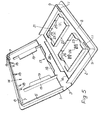
- Figures 1 and 2 are perspective views of a first embodiment shown in the open position and closed position, respectively,
- Figure 3 is a side view from the right-hand side of Figure 1,
- Figure 4 is an end view of Figure 1, and
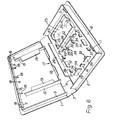
- Figures 5 and 6 are perspective views of pen second and third embodiments, respectively.
- Referring first to Figures 1 to 4, the first embodiment is designed to hold a floppy magnectic disc on one side and a cassette of magnetic tape and an instructional booklet or the like on the other side. The container is of general book form and comprises two rectangular,
planar members spine 3, the hinges being formed by respective integral strips 4 of material of smaller thickness than that of themembers - The
members upstanding flange flange 5 and provided with a rib 8 facing thespine 3, the tongues being engageable withrespective pockets 9 provided adjacent theflange 6. Eachpocket 9 is defined by part of theflange 6, an opposed lug 11 extending from the inner face of themember 2, and twosides 12 having V-shaped upper edges to allow flexing of the lugs 11. These components are illustrated in Figure 1 at the broken away portion of theflange 6. Each lug 11 is provided with a rib 13 facing inwardly of thepocket 9, the ribs 8 of the tongues 7 passing and snapping behind the respective ribs 13 when the container is closed and being disengaged as the container is opened. - The floppy disc holder provided on the inside of the
member 1 is in the form of acompartment 14 which is defined by two opposed pair of first walls, the first pair comprising twoupstanding members 15 extending from the adjacent edge of thespine 3 to a point short of the portion of theflange 5 opposite the spine, and the second pair comprising in effect part of that portion of theflange 5 and anupstanding member 16 extending along the associated edge of thespine 3 substantially between thewalls 15. Thewall 16 has acentral discontinuity 17, and ramp means 18 in the form of a triangular fillets extend from theflange portion 5 towards thewall 16. Thecompartment 14 is completed by second wall means formed by twoextensions 19 of therespective walls 15, the extensions being parallel to the inside face of themember 1 and defining therewith the depth of thecompartment 14. - The compartment is dimensioned so as to receive a 5.25 inch (13.3 cm) disc (not shown) as a snug fit, as opposed to a tight fit, and it will be seen that a disc is accommodated entirely within the compartment whereby it is protected on all sides and edges. The disc can to some extent "float" within the
compartment 14 which helps to avoid it being subjected to any forces during handling or storage of the container. The disc is retained in thecompartment 14 however the open container might be oriented so that it cannot inadvertently fall out but is readily removed by engaging, through thediscontinuity 17 in thewall 16, the edge adjacent thespine 3 and pushing it against the ramp means 18 up which the opposite edge rises so that the disc is presented for grasping and final removal from the compartment. The top of the ramp means 18 are shown flush with the top edge of theflange 5 but they may be made to extend slightly proud thereof to ensure that the disc clears the flange on removal. - As already mentioned, the other half of the container is designed to hold a cassette and a booklet or the like. The cassette (not shown) is accommodated within a
recess 21 defined by an upstandingrectangular flange 22 two opposed portions of which have arcuate cut-outs 23 to enable the cassette to be inserted and removed. Two cruciform members 24 (only one shown) are provided within therecess 21 to receive and locate the centres of the tape spools of the cassette in conventional fashion.Ribs 25 are provided on the inside face of theflange 22 to engage the sides of the cassette to ensure a friction fit so that the cassette too will not fall out inadvertently. - The booklet or the like (not shown) is accommodated over the
cassette recess 22 within the confines of theflange 6 which is augmented on the fourth edge of themember 2 along thespine 3 by ashort wall 26. In order to prevent the booklet flopping into the space between theflange 22 and theflange 6 andwall 26, fourupstanding walls 27 are provided to support the booklet in this area. - Turning now to the embodiment of Figure 5, this is identical to that of Figures 1 to 4 except for the fact that it is designed to hold two tape cassettes in the
member 2 instead of one. Similar components have been given like reference numerals and it will be noted that the only difference between the two embodiments is that in Figure 4 the two cassette recesses formed by therespective flanges 22 have been turned through 90° and that thewalls 27 have been dispensed with because the upper edges of theflanges 22 provide all the necessary support for the booklet or the like. - The third embodiment shown in Figure 6 is again identical in basic construction to that of Figure 1, the difference this time being that it is designed to hold in the
member 2 one cassette and one 3 inch (7.6 cm) diskette and/or one 3.5 inch (8.9 cm) diskette. The smaller diskette (not shown) will normally be contained in a protective envelope or box (for example of a rigid or semi-rigid synthetic plastics material) measuring approximately 3 inches (7.6 cm) by 4 inches (10.2 cm) and this is a snug fit basically between two opposedshort walls 31 andtransitions 32 betweensteps 33 and 34 of four double-steppedmember 35, two of which are associated with one side of the diskette and two with the opposed side. The smaller diskette sits on thefirst step 33 of eachmember 35, and is thus slightly spaced from the base of themember 2, and is positively retained in position byribs 36 on two opposed pairs of upstanding members 37. This spacing of the smaller diskette from the base of themember 2 helps protect the diskette from any forces applied to the outside of themember 2 and enables a finger nail to be inserted beneath the diskette to help raise the latter for removal. The members 37 of each pair are disposed on opposite sides of awall 31 and spaced therefrom, the members 37 being shorter than thewalls 31. Although not discernible from the Figure 5, the members 37 are inclined slightly inwardly of the area for containing the diskettes so that they effectively spring load theribs 36 and are forced outwardly by a diskette being inserted, whereby the adjacent edges snap under theribs 36 and the diskette is held firm. - Two of the
stepped members 35 extend at right angles from a single short wall 38 defining one side boundary for the larger diskette (also not shown), and the other two extend at right angles from separateshort walls 39 which define the opposed boundary, these two walls being opposed to, but offset from, the single wall 38. On each side of the single wall 38 and inbetween the twowalls 39 there is provided amember 41 having arib 42 which serve the same purpose, relative to the large diskette, as theribs 36 for the smaller diskette, themembers 41 also being inclined inwardly of the area for retaining the larger diskette although again this is not seen from Figure 5. The larger diskette, which measures approximately 3.5 inches by 3.5 inches (8.9cm x 8.9cm), sits on the upper step 34 of thestepped member 35 and is thus physically separated from, and supported independently of, the smaller diskette. In order that theribs 42 can snap over the adjacent edges of the larger diskette, themembers 41 are taller than the members 37 to accommodate the relative positioning of the two diskettes. The fact the larger diameter diskette is in fact of smaller overall size than the smaller diskette means that it does not span thewalls 31 but it is held firmly by theribs 42 and so does not readily move about between thewalls 31. - Another feature of the container of Figure 6 not possessed by the containers of Figures 1 and 5 is that of the
bar 43 provided across the corner of the cassette recess 21 at the base of themember 2, whereby the cassette is supported slightly spaced from the latter. However, this feature may be incorporated into the other embodiments. As before, an instruction booklet or the like can be accommodated on top of the cassette and the diskettes. - All of the illustrated embodiments of the invention have been designed for production by injection moulding from a rigid or semi-rigid synthetic plastics material to give structural strength but in any event the accommodation of the floppy disc within its own compartment ensures protection of the latter. In the illustrated embodiments, the
compartments 14 are designed to hold one floppy disc but the depth of thecompartments 14 could be increased to hold two or more. If a number of containers are stacked one upon the other or if one or more containers are stacked with other objects the discs housed in the compartments are not subjected to harmful sustained pressure principally because the abuttingflanges wall 26 of each container provide a rigid peripheral support thus protecting all of the contents of the container. Even if localised pressure is exerted on one of themembers - The container would normally carry identifying material on the outside and to this end, two slightly raised ridges 28 (Figure 4) are provided along the edges of the outer faces of the
members spine 3 which provide surfaces for heat sealing or otherwise securing respective opposed edges of a thin rectangular film of a transparent synthetic plastics material (not shown) which overlies the whole of the exterior of the container, with the other opposed edges of the film being free for the insertion of a sheet of identifying material. Theridges 28 prevent the sheet from being gripped so tightly between the film and themembers - It will be appreciated that a container in accordance with the present invention can be made from any material (if not injection moulded) and that it can be designed to hold floppy discs on one or both of the cover members if cassettes or diskettes do not have to be accommodated.
Claims (10)
Applications Claiming Priority (2)
| Application Number | Priority Date | Filing Date | Title |
|---|---|---|---|
| GB8432146 | 1984-12-20 | ||
| GB848432146A GB8432146D0 (en) | 1984-12-20 | 1984-12-20 | Containers for software |
Publications (2)
| Publication Number | Publication Date |
|---|---|
| EP0186359A2 true EP0186359A2 (en) | 1986-07-02 |
| EP0186359A3 EP0186359A3 (en) | 1987-01-07 |
Family
ID=10571477
Family Applications (1)
| Application Number | Title | Priority Date | Filing Date |
|---|---|---|---|
| EP85308919A Withdrawn EP0186359A3 (en) | 1984-12-20 | 1985-12-09 | Containers for software |
Country Status (2)
| Country | Link |
|---|---|
| EP (1) | EP0186359A3 (en) |
| GB (1) | GB8432146D0 (en) |
Cited By (13)
| Publication number | Priority date | Publication date | Assignee | Title |
|---|---|---|---|---|
| FR2621163A1 (en) * | 1987-09-24 | 1989-03-31 | Kunimune Kogyosho Co Ltd | CASE FOR COMPACT DISCS |
| EP0384742A2 (en) * | 1989-02-21 | 1990-08-29 | AMPEX MEDIA CORPORATION(State of Delaware) | Storage container for digital audio tape cassettes |
| EP0531113A2 (en) * | 1991-09-04 | 1993-03-10 | Sony Corporation | Case for a disc cartridge |
| EP0549360A2 (en) * | 1991-12-27 | 1993-06-30 | Sony Corporation | Storage case for disc-shaped recording media |
| EP0566403A2 (en) * | 1992-04-16 | 1993-10-20 | Sony Corporation | Enclosures for disks |
| EP0568298A1 (en) * | 1992-04-30 | 1993-11-03 | John Hersey-Walker | A container for a compact disc, a minidisc, a cassette or a compact cassette |
| EP0586141A1 (en) * | 1992-09-04 | 1994-03-09 | Sony Corporation | Casings for disc cartridges |
| GB2282797A (en) * | 1993-10-07 | 1995-04-19 | Dennish Limited | Packaging element |
| FR2734940A1 (en) * | 1995-06-02 | 1996-12-06 | Mathieu Bruno | Video cassette case |
| GB2309963A (en) * | 1993-07-20 | 1997-08-13 | Sony Corp | Case for a tape cassette |
| EP0810165A1 (en) * | 1995-12-15 | 1997-12-03 | Sony Corporation | Housing case for a disk cartridge |
| EP1564156A1 (en) * | 2002-10-28 | 2005-08-17 | Matsushita Electric Industrial Co., Ltd. | Case |
| DE202008014204U1 (en) * | 2008-05-20 | 2009-04-16 | Kempa, Sebastian | HDD box |
Citations (5)
| Publication number | Priority date | Publication date | Assignee | Title |
|---|---|---|---|---|
| US3743081A (en) * | 1971-02-25 | 1973-07-03 | Grace W R & Co | Cassette album container |
| GB2091219A (en) * | 1981-01-21 | 1982-07-28 | Egly Robert A | Magnetic disc storage case |
| EP0109092A1 (en) * | 1982-11-16 | 1984-05-23 | Otto Burgschweiger | Container |
| GB2132588A (en) * | 1982-12-23 | 1984-07-11 | Ajec Marketing Limited | Cassette for storing cards, discs and the like |
| US4511034A (en) * | 1984-04-23 | 1985-04-16 | Pan You Chwen | Computer diskette cases |
-
1984
- 1984-12-20 GB GB848432146A patent/GB8432146D0/en active Pending
-
1985
- 1985-12-09 EP EP85308919A patent/EP0186359A3/en not_active Withdrawn
Patent Citations (5)
| Publication number | Priority date | Publication date | Assignee | Title |
|---|---|---|---|---|
| US3743081A (en) * | 1971-02-25 | 1973-07-03 | Grace W R & Co | Cassette album container |
| GB2091219A (en) * | 1981-01-21 | 1982-07-28 | Egly Robert A | Magnetic disc storage case |
| EP0109092A1 (en) * | 1982-11-16 | 1984-05-23 | Otto Burgschweiger | Container |
| GB2132588A (en) * | 1982-12-23 | 1984-07-11 | Ajec Marketing Limited | Cassette for storing cards, discs and the like |
| US4511034A (en) * | 1984-04-23 | 1985-04-16 | Pan You Chwen | Computer diskette cases |
Cited By (28)
| Publication number | Priority date | Publication date | Assignee | Title |
|---|---|---|---|---|
| FR2621163A1 (en) * | 1987-09-24 | 1989-03-31 | Kunimune Kogyosho Co Ltd | CASE FOR COMPACT DISCS |
| DE3803732A1 (en) * | 1987-09-24 | 1989-04-13 | Kunimune Kogyosho Co | CONTAINER FOR COMPACT DISKS |
| EP0384742A2 (en) * | 1989-02-21 | 1990-08-29 | AMPEX MEDIA CORPORATION(State of Delaware) | Storage container for digital audio tape cassettes |
| EP0384742A3 (en) * | 1989-02-21 | 1991-07-03 | AMPEX MEDIA CORPORATION(State of Delaware) | Storage container for digital audio tape cassettes |
| EP0531113A3 (en) * | 1991-09-04 | 1993-11-18 | Sony Corp | Case for a disc cartridge |
| EP0531113A2 (en) * | 1991-09-04 | 1993-03-10 | Sony Corporation | Case for a disc cartridge |
| KR100275350B1 (en) * | 1991-09-04 | 2001-01-15 | 이데이 노부유끼 | Case for disc cartridge and holding member for holding disc cartridge |
| EP0549360A2 (en) * | 1991-12-27 | 1993-06-30 | Sony Corporation | Storage case for disc-shaped recording media |
| EP0549360A3 (en) * | 1991-12-27 | 1993-11-10 | Sony Corp | Storage case for disc-shaped recording media |
| US5293995A (en) * | 1991-12-27 | 1994-03-15 | Sony Corporation | Storage case for disc-shaped recording media contained within substantially flat rectangular housings |
| EP0566403A2 (en) * | 1992-04-16 | 1993-10-20 | Sony Corporation | Enclosures for disks |
| EP0566403A3 (en) * | 1992-04-16 | 1993-12-22 | Sony Corp | Enclosures for disks |
| AU664881B2 (en) * | 1992-04-16 | 1995-12-07 | Sony Corporation | Storage container for mini-disk cartridges |
| EP0568298A1 (en) * | 1992-04-30 | 1993-11-03 | John Hersey-Walker | A container for a compact disc, a minidisc, a cassette or a compact cassette |
| US5415291A (en) * | 1992-09-04 | 1995-05-16 | Sony Corporation | Casing for multiple disc cartridges |
| EP0586141A1 (en) * | 1992-09-04 | 1994-03-09 | Sony Corporation | Casings for disc cartridges |
| GB2311277A (en) * | 1993-07-20 | 1997-09-24 | Sony Corp | Case for a tape cassette |
| GB2309963A (en) * | 1993-07-20 | 1997-08-13 | Sony Corp | Case for a tape cassette |
| GB2309963B (en) * | 1993-07-20 | 1997-11-12 | Sony Corp | Case for a tape cassette |
| GB2311277B (en) * | 1993-07-20 | 1997-11-12 | Sony Corp | Case for a tape cassette |
| GB2282797A (en) * | 1993-10-07 | 1995-04-19 | Dennish Limited | Packaging element |
| FR2734940A1 (en) * | 1995-06-02 | 1996-12-06 | Mathieu Bruno | Video cassette case |
| EP0810165A1 (en) * | 1995-12-15 | 1997-12-03 | Sony Corporation | Housing case for a disk cartridge |
| EP0810165A4 (en) * | 1995-12-15 | 1998-04-15 | Sony Corp | Housing case for a disk cartridge |
| US5931296A (en) * | 1995-12-15 | 1999-08-03 | Sony Corporation | Accomodating case for disc cartridge |
| EP1564156A1 (en) * | 2002-10-28 | 2005-08-17 | Matsushita Electric Industrial Co., Ltd. | Case |
| EP1564156A4 (en) * | 2002-10-28 | 2007-12-05 | Matsushita Electric Ind Co Ltd | Case |
| DE202008014204U1 (en) * | 2008-05-20 | 2009-04-16 | Kempa, Sebastian | HDD box |
Also Published As
| Publication number | Publication date |
|---|---|
| GB8432146D0 (en) | 1985-01-30 |
| EP0186359A3 (en) | 1987-01-07 |
Similar Documents
| Publication | Publication Date | Title |
|---|---|---|
| US4793477A (en) | Book carrier for cassette and compact disc | |
| US4771890A (en) | Disk retainer and packaging system for optical disks | |
| US4676374A (en) | Hard case floppy disk holder | |
| US5396987A (en) | Containers for compact discs | |
| EP0186359A2 (en) | Containers for software | |
| EP0802539B1 (en) | Compact disc storage package | |
| US5542531A (en) | Holder for compact disc having carrier part | |
| EP0531113B1 (en) | Case for a disc cartridge | |
| US4425997A (en) | Article display and holder apparatus | |
| EP0252226B1 (en) | Disk retainer and packaging system for optical disks | |
| US5464091A (en) | Protective covers | |
| US3561595A (en) | Tape cartridge holder | |
| EP0934590B1 (en) | A holder for a planar data storage medium | |
| US4545486A (en) | Container and storage system for photographic prints and negatives | |
| US20060289318A1 (en) | Closable package for retaining multiple discs in pouch-type holders or disc-receiving trays | |
| US5363956A (en) | Container for plurality of stackable objects | |
| US4951814A (en) | Storage container for digital audio tape cassettes | |
| EP0568298A1 (en) | A container for a compact disc, a minidisc, a cassette or a compact cassette | |
| EP1551731A2 (en) | Versatile cd/dvd type pocket assembly | |
| US4928818A (en) | Container for compact disks | |
| EP0549360A2 (en) | Storage case for disc-shaped recording media | |
| EP0050485B1 (en) | Unitary hinged box-type container | |
| US4519893A (en) | Magnetic disc storage container | |
| EP0001353B1 (en) | Container for magnetic memory storage members | |
| GB2162826A (en) | Case for magnetic recording medium |
Legal Events
| Date | Code | Title | Description |
|---|---|---|---|
| PUAI | Public reference made under article 153(3) epc to a published international application that has entered the european phase |
Free format text: ORIGINAL CODE: 0009012 |
|
| AK | Designated contracting states |
Kind code of ref document: A2 Designated state(s): BE DE FR GB IT NL |
|
| PUAL | Search report despatched |
Free format text: ORIGINAL CODE: 0009013 |
|
| AK | Designated contracting states |
Kind code of ref document: A3 Designated state(s): BE DE FR GB IT NL |
|
| 17P | Request for examination filed |
Effective date: 19870624 |
|
| 17Q | First examination report despatched |
Effective date: 19890606 |
|
| STAA | Information on the status of an ep patent application or granted ep patent |
Free format text: STATUS: THE APPLICATION IS DEEMED TO BE WITHDRAWN |
|
| 18D | Application deemed to be withdrawn |
Effective date: 19890704 |