EP0184860B1 - Ac signal generating apparatus - Google Patents
Ac signal generating apparatus Download PDFInfo
- Publication number
- EP0184860B1 EP0184860B1 EP85115939A EP85115939A EP0184860B1 EP 0184860 B1 EP0184860 B1 EP 0184860B1 EP 85115939 A EP85115939 A EP 85115939A EP 85115939 A EP85115939 A EP 85115939A EP 0184860 B1 EP0184860 B1 EP 0184860B1
- Authority
- EP
- European Patent Office
- Prior art keywords
- signal generating
- phase
- generating means
- signal
- output
- Prior art date
- Legal status (The legal status is an assumption and is not a legal conclusion. Google has not performed a legal analysis and makes no representation as to the accuracy of the status listed.)
- Expired - Lifetime
Links
Images


Classifications
-
- H—ELECTRICITY
- H02—GENERATION; CONVERSION OR DISTRIBUTION OF ELECTRIC POWER
- H02K—DYNAMO-ELECTRIC MACHINES
- H02K29/00—Motors or generators having non-mechanical commutating devices, e.g. discharge tubes or semiconductor devices
- H02K29/06—Motors or generators having non-mechanical commutating devices, e.g. discharge tubes or semiconductor devices with position sensing devices
- H02K29/08—Motors or generators having non-mechanical commutating devices, e.g. discharge tubes or semiconductor devices with position sensing devices using magnetic effect devices, e.g. Hall-plates, magneto-resistors
-
- H—ELECTRICITY
- H02—GENERATION; CONVERSION OR DISTRIBUTION OF ELECTRIC POWER
- H02P—CONTROL OR REGULATION OF ELECTRIC MOTORS, ELECTRIC GENERATORS OR DYNAMO-ELECTRIC CONVERTERS; CONTROLLING TRANSFORMERS, REACTORS OR CHOKE COILS
- H02P6/00—Arrangements for controlling synchronous motors or other dynamo-electric motors using electronic commutation dependent on the rotor position; Electronic commutators therefor
- H02P6/14—Electronic commutators
- H02P6/16—Circuit arrangements for detecting position
Definitions
- the present invention relates to an AC signal generating apparatus for generating an AC signal as a rotary magnetic pole member rotates, and in particular to an AC signal generating apparatus suitable to detection of a magnetic pole position in control of a brushless DC motor.
- a magnet coupled to the motor shaft directly or via a coupling, for example, is provided and the magneticflux is detected by Hall devices or search coils.
- This magnet is magnetized at positions corresponding to those of the magnetic poles of the motor.
- the current phase and magnitude of the servomotor in each of the U and V phases are determined.
- Fig. 1 shows an example of a control circuit used for an AC servomotor of the prior art.
- the control circuits of Fig. 1 includes a main circuit of the servomotor controller 1, a servomotor 2, an encoder 3 which is an AC signal generating apparatus, an error amplifier 4, multipliers 5 and 6, comparator circuits 7 to 12, current control amplifiers 13 to 15, PWM signal generators 16 to 18, current detectors 19 and 20, and a speed detector circuit 21.
- a speed command signal V N * and a speed signal V N fed from the encoder 3 are supplied to the comparator circuit 7 to yield the difference between them.
- the difference is amplified by the error amplifier4.
- the output of the error amplifier 4 is multiplied with magnetic pole position detection signals U and V in the multipliers 5 and 6, respectively.
- the multipliers 5 and 6 send out current command signals of the U phase and V phase, respectively.
- the signals detected by the current detectors 19 and 20 are compared respectively in the comparator circuits 8 and 9, amplified respectively by current control amplifiers 13 and 14, converted into PWM waveforms respectively by the PWM signal generators 16 and 17, and applied to the servomotor control main circuit 1 as transistor base signals.
- the outputs of the comparator circuits 8 and 9 are combined to produce a W phase signal in the comparator circuit 10.
- the current detection signals from the current detectors 19 and 20 are combined to produce the current detection signal of the W, phase in the comparator circuit 12.
- the outputs of comparator circuits 10 and 12 are applied to the comparator circuit 11 to produce their difference.
- the output of the comparator circuit 11 is supplied to the servomotor controller main circuit 1 via the current control amplifier 15 and the PWM signal generator 18 as the transistor base signal. These signals let flow currents successively through the stator windings of the motor 2 to control the AC servomotor in accordance with the speed commands.
- the W phase is obtained by combining the U phase and the V phase. This method is frequently used since neither the W phase current detector, nor W phase detection signal wiring from the encoder, nor the W phase multiplier is required.
- the U phase detection signal and the V phase detection signal of the servomotor are obtained by detecting the magnetic flux of the magnet magnetized for detecting the magnetic pole position.
- the peak portion is deformed to contain harmonics as much as several % to ten plus several %.
- Most of the harmonics comprise the third harmonics.
- DE-A-2 915 987 discloses a three phase encoder whereby the three voltage signals are summed and divided by three in order to determine the D.C. component of the voltage signals and this D.C. component is subtracted from each voltage signal.
- the rim of rotary disks which is scanned by inductive sensors disposed around the disks are suitably shaped. But said publication discloses no processing of the signals in orderto diminish the third harmonic component.
- the W phase In case of the method whereby the W phase is obtained by combining the U phase and V phase, the third harmonics assume the same phase in the U phase and V phase. Accordingly, the W phase contains twice as much as the third harmonic of each of the U phase and the V phase.
- Fig. 2 concretely shows the magnetic pole position detection waveforms of the U, V and W phases.
- the U phase and V phase contain the third harmonics having the same phase as indicated by broken lines.
- the W phase is obtained by combining the U phase and the V phase as Accordingly, the third harmonic contained in the W phase is twice in amplitude and opposite in polarity as compared with each of the U phase and the V phase as represented by a broken line of the W phase.
- the waveform of the W phase is large in amplitude and is similar to triangular waves.
- the W phase Since the current commands are produced on the basis of the magnetic pole position detection signals of the U, V and W phases, the W phase has a large current peak value. This results in a drawback that the current flowing through the transistor used in the servomotor controller becomes unreasonably large. In addition, torque pulsation is incurred from the third harmonic flowing through the servomotor.
- An object of the present invention is to provide an AC signal generating apparatus wherein the third harmonic contained in the magnetic pole position detection signal is minimized.
- the third harmonic contained in the U, V and W phases have the same phase. Therefore, the third haromonic can be eliminated by deriving the difference between outputs of two phases. Further, only the third harmonic can be extracted by adding outputs of the three phases. By subtracting the third harmonic from each phase output, therefore, it is possible obtain an output free from the third harmonic or containing a smaller quantity of the third harmonic.
- the output V is used with respect to the output U
- the third harmonic contained in the output V has a phase difference n with respect to that contained in the output U. By adding the outputs of the two phases U and V, therefore, it is possible to obtain an output which does not contain the third harmonic or which contains only a small quantity of the third harmonic.
- the present invention is based upon such a principle and is disclosed in claim 1.
- a rotary magnetic pole member 30 has a pair of poles composed of an N pole 200 and an S pole 201.
- Hall devices 31 to 33 are the first to the third signal generating means, each of which is confronted by the N pole or the S pole of the rotary magnetic pole member.
- Calculation means 300 is composed of comparator circuits 34 to 36 and a divide-by-three circuit 37.
- the magnetic 30 has pole positions relatively aligned to the magnetic pole positions of the servomotor.
- the magnetic flux of the magnet 30 is detected by the Hall devices 31 to 33.
- the Hall devices 31 to 33 are so located as to be displaced by 120° one another in electric angle and produce the u, v and w phases, respectively.
- Figs. 4A and 4B shows the relationship between the magnetic pole position detecting magnet and the Hall devices when the motor has two and four magnetic poles.
- the Hall devices are disposed at positions of 0°, 120° and 240° in electric angles. When the number of the magnetic poles is large, the Hall devices are disposed based upon the same concept.
- Fig. 4A shows a case of two magnetic poles and Fig. 4B shows a case of four magnetic poles.
- the Hall devices may be displaced by a multiple of 360° in electric angle.
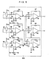
- Fig. 5 shows a concrete embodiment of the present invention.
- Resistors 53 to 75, operational amplifiers 76 to 81, and variable resistors 82 to 86 are included in the circuit of Fig. 5.
- 1 01 to I C3 denote control currents of Hall devices.
- the operational amplifier 76 amplifies the signal fed from a Hall device 31 in a differential mode to detect the u phase. In the same way, the operational amplifier detects the v phase and the operational amplifier 78 detects the w phase.
- Variable resistors 60, 61 and 62 are provided for zero level adjustment and variable resistors 85 and 86 are provided for gain adjustment. The signals of u, v and w phases are so adjusted as to have equal magnitudes and then added together in the operational amplifier 81.
- resistors 71 to 73 have equal resistance values and the resistor 74 has a resistance value which is equal to one third of that of each of the resistors 71 to 73, together by the operational amplifier 80 to produce the V phase signal with the third harmonic cancelled.
- the resistor 63 has a resistance value equal to that of the resistor 65.
- the resistor 64 has a resistance value equal to that of the resistor 66.
- Fig. 6 is advantageous in that the circuit configuration is simple provided that the control current power sources of the Hall devices are insulated and isolated.
- Fig. 6 shows waveforms of the u, v, w and w phases.
- a magnet having a number of magnetic poles such as a magnet having four magnetic poles as illustrated in Fig. 4, it is difficult to make uniform the magnetization magnitude of respective poles, resulting in somewhat unevenness.
- portions @, b, ⁇ and @ are respectively detected by receiving the magnetic flux from the same poles of the magnet, i.e., from the same pair of poles simultaneously.
- the signal u+v+w is to be produced, the u and v phase signals belong to the portion a while the w phase signal belongs to the portion @, for example. In such a case, there occurs a difference between the voltage magnitudes.
- the w phase signal represented by a broken line of Fig. 6 as the output of the third signal generating means is not obtained by inverting the w phase but obtained from a Hall device located at a position w.
- Fig. 7 shows how the hall device for detecting w is located.
- the hall device is fixed at a position of 60° between the first signal generating means 31 and the second signal generating means 32.
- the w phase signal also belongs to the portion a.
- the error in the fundamental frequency is advantageously reduced as compared with the u, v and w locations disposed at an interval of 120°.
- Fig. 8 shows the detection circuit corresponding to the configuration of Fig. 7.
- the configuration of Fig. 8 is the same as that of Fig. 5 excepting a w phase detection circuit. Due to the difference in the location of the Hall device, the output voltage of the Hall device of the w phase is opposite in polarity to that of the Hall device of the w phase illustrated in Fig. 5. Therefore, inputs to the operational amplifier 78 for differential amplification are inverted.
- Other parts of Fig. 9 are the same as those of Fig. 5.
- u+v and v+w are used to cancel the third harmonic.
- Signals U, v and w represent signals obtained by inverting the signals u, v and w.
- their respective third harmonics are inverted in polarity and added together to be cancelled.
- signals u+v and v+w lead in phase by 30° with respect to the u and v phases, respectively. Therefore, it is possible to make the encoder output signals U and V coincident with the magnetic pole positions by displacing the magnetic pole positions of the motor relatively by 30° or by displacing the locations of the Hall devices by 30° in the opposite direction.
- Fig. 10 shows the principle for realizing the method illustrated in Fig. 9.
- Reference numerals 110 and 111 denote comparator circuits. Signals detected by the Hall devices 31 and 32 are supplied to a comparator circuit 110 to produce the U phase signal represented as u-v. And signals detected by the Hall devices 32 and 33 are supplied to a comparator circuit 111 to produce the V phase signal represented as v-w.
- Fig. 11 shows a concrete embodiment of the present invention.
- Resistors 123 to 143, variable resistors 144 to 148, and operational amplifiers 149 to 154 are included in the circuit of Fig. 12.
- the -u, -v, -w phase signals are detected by the operational amplifiers 149, 150 and 151.
- the signal u+v is sent out from the operational amplifier 152 as the U phase signal.
- the signal v+w is sent out from the operational amplifier 153 as the V phase signal.
- variable resistors 144 to 146 are provided for zero level adjustment.
- variable resistors 147 and 148 are provided for gain adjustment.
- Fig. 12 shows an embodiment in which the Hall device voltage outputs are coupled in series to reduce the number of operational amplifiers.
- Resistors 163 and 168, variable resistors 170 to 172, and operational amplifiers 173 and 174 are included in the embodiment of Fig. 13.
- the U, v and w phase signals are detected by the Hall devices 31, 32 and 33, respectively.
- the operational amplifier 173 sends out the signal as the U phase signal.
- the embodiment of Fig. 12 has an advantage of simple circuit configuration provided that the power sources for letting flow the control currents through the Hall devices 31 to 33 are respectively isolated and insulated.
- Hall devices are used for detecting the magnetic flux.
- any means capable of detecting the magnetic flux such as search coils disposed so as to be confronted by the magnetic poles may be used instead of the Hall devices.
Landscapes
- Engineering & Computer Science (AREA)
- Power Engineering (AREA)
- Control Of Motors That Do Not Use Commutators (AREA)
- Length Measuring Devices With Unspecified Measuring Means (AREA)
Description
- The present invention relates to an AC signal generating apparatus for generating an AC signal as a rotary magnetic pole member rotates, and in particular to an AC signal generating apparatus suitable to detection of a magnetic pole position in control of a brushless DC motor.
- An AC servomotor comprising a brushless DC motor must detect the U, V and W phases of the magnetic pole position. (However, one of the U, V and W phase can be omitted to be detected since it can be calculated from two other phases by using an expression W=-(U+V), for example).
- In one of methods for detecting the magnetic pole position, a magnet coupled to the motor shaft directly or via a coupling, for example, is provided and the magneticflux is detected by Hall devices or search coils.
- This magnet is magnetized at positions corresponding to those of the magnetic poles of the motor.
- On the basis of the detected magnetic pole position signal, the current phase and magnitude of the servomotor in each of the U and V phases are determined.
- Fig. 1 shows an example of a control circuit used for an AC servomotor of the prior art.
- The control circuits of Fig. 1 includes a main circuit of the servomotor controller 1, a servomotor 2, an encoder 3 which is an AC signal generating apparatus, an
error amplifier 4,multipliers 5 and 6, comparator circuits 7 to 12,current control amplifiers 13 to 15,PWM signal generators 16 to 18,current detectors speed detector circuit 21. - A speed command signal VN * and a speed signal VN fed from the encoder 3 are supplied to the comparator circuit 7 to yield the difference between them. The difference is amplified by the error amplifier4. The output of the
error amplifier 4 is multiplied with magnetic pole position detection signals U and V in themultipliers 5 and 6, respectively. Themultipliers 5 and 6 send out current command signals of the U phase and V phase, respectively. - The signals detected by the
current detectors comparator circuits current control amplifiers PWM signal generators comparator circuits comparator circuit 10. In addition, the current detection signals from thecurrent detectors comparator circuit 12. The outputs ofcomparator circuits current control amplifier 15 and the PWM signal generator 18 as the transistor base signal. These signals let flow currents successively through the stator windings of the motor 2 to control the AC servomotor in accordance with the speed commands. - As shown in this example, the W phase is obtained by combining the U phase and the V phase. This method is frequently used since neither the W phase current detector, nor W phase detection signal wiring from the encoder, nor the W phase multiplier is required.
- The U phase detection signal and the V phase detection signal of the servomotor are obtained by detecting the magnetic flux of the magnet magnetized for detecting the magnetic pole position. However, it is comparatively difficult to magnetize the magnet so that the sinusoidal output may so produced. Eventually the peak portion is deformed to contain harmonics as much as several % to ten plus several %. Most of the harmonics comprise the third harmonics.
- DE-A-2 915 987 discloses a three phase encoder whereby the three voltage signals are summed and divided by three in order to determine the D.C. component of the voltage signals and this D.C. component is subtracted from each voltage signal. To approximate a sinusoidal waveform provided by the voltage signals the rim of rotary disks which is scanned by inductive sensors disposed around the disks are suitably shaped. But said publication discloses no processing of the signals in orderto diminish the third harmonic component.
- In case of the method whereby the W phase is obtained by combining the U phase and V phase, the third harmonics assume the same phase in the U phase and V phase. Accordingly, the W phase contains twice as much as the third harmonic of each of the U phase and the V phase. Fig. 2 concretely shows the magnetic pole position detection waveforms of the U, V and W phases. The U phase and V phase contain the third harmonics having the same phase as indicated by broken lines. The W phase is obtained by combining the U phase and the V phase as

- While the U phase and the V phase have similar waveforms, the waveform of the W phase is large in amplitude and is similar to triangular waves.
- Since the current commands are produced on the basis of the magnetic pole position detection signals of the U, V and W phases, the W phase has a large current peak value. This results in a drawback that the current flowing through the transistor used in the servomotor controller becomes unreasonably large. In addition, torque pulsation is incurred from the third harmonic flowing through the servomotor.
- An object of the present invention is to provide an AC signal generating apparatus wherein the third harmonic contained in the magnetic pole position detection signal is minimized.
- As evident from Fig. 2, the third harmonic contained in the U, V and W phases have the same phase. Therefore, the third haromonic can be eliminated by deriving the difference between outputs of two phases. Further, only the third harmonic can be extracted by adding outputs of the three phases. By subtracting the third harmonic from each phase output, therefore, it is possible obtain an output free from the third harmonic or containing a smaller quantity of the third harmonic. When the output V is used with respect to the output U, the third harmonic contained in the output V has a phase difference n with respect to that contained in the output U. By adding the outputs of the two phases U and V, therefore, it is possible to obtain an output which does not contain the third harmonic or which contains only a small quantity of the third harmonic.
- The present invention is based upon such a principle and is disclosed in claim 1.
- Fig. 1 shows an AC servomotor control circuit of the prior art. Fig. 2 shows magnet pole position detection signals when a magnetic pole position detecting magnet and Hall devices are used. Fig. 3 shows the principle of an apparatus according to the present invention. Figs. 4A and 4B show positional relationship between the magnetic pole position detecting magnet and the Hall devices. Fig. 5 shows a concrete embodiment of an apparatus according to the present invention. Fig. 6 shows another concrete embodiment of the apparatus according to the present invention. Fig. 7 shows magnetic pole detection signals. Fig. 8 shows the positional relationship between the magnetic pole position detecting magnet and the Hall devices in the present invention apparatus. Fig. 9 shows still another concrete embodiment of the present invention apparatus. Fig. 10 shows the waveform combination. Fig. 11 shows the principle of a variant of the present invention apparatus. Figs. 12 and 13 show other variants of the present invention apparatus.
- Fig. 3 shows the principle of the present invention.
- A rotary
magnetic pole member 30 has a pair of poles composed of anN pole 200 and anS pole 201.Hall devices 31 to 33 are the first to the third signal generating means, each of which is confronted by the N pole or the S pole of the rotary magnetic pole member. Calculation means 300 is composed ofcomparator circuits 34 to 36 and a divide-by-threecircuit 37. - The magnetic 30 has pole positions relatively aligned to the magnetic pole positions of the servomotor.
- The magnetic flux of the
magnet 30 is detected by theHall devices 31 to 33. TheHall devices 31 to 33 are so located as to be displaced by 120° one another in electric angle and produce the u, v and w phases, respectively. - . By adding the u, v and w phase detection signals in the
comparator circuit 36, the fundamental component is eliminated and the third harmonic remains. Since the value of the third harmonic is three times that of one phase component, it is reduced to one third by thecircuit 37. By subtracting the output signal of thecircuit 37 from the detection signals of the u and v phases in thecomparator circuits - Figs. 4A and 4B shows the relationship between the magnetic pole position detecting magnet and the Hall devices when the motor has two and four magnetic poles. The Hall devices are disposed at positions of 0°, 120° and 240° in electric angles. When the number of the magnetic poles is large, the Hall devices are disposed based upon the same concept.
- Fig. 4A shows a case of two magnetic poles and Fig. 4B shows a case of four magnetic poles.
- In case of a large number of magnetic poles, the Hall devices may be displaced by a multiple of 360° in electric angle.
- Fig. 5 shows a concrete embodiment of the present invention.
Resistors 53 to 75,operational amplifiers 76 to 81, andvariable resistors 82 to 86 are included in the circuit of Fig. 5. 101 to IC3 denote control currents of Hall devices. - The
operational amplifier 76 amplifies the signal fed from aHall device 31 in a differential mode to detect the u phase. In the same way, the operational amplifier detects the v phase and theoperational amplifier 78 detects the w phase.Variable resistors variable resistors operational amplifier 81. - If the
resistors 71 to 73 have equal resistance values and the resistor 74 has a resistance value which is equal to one third of that of each of theresistors 71 to 73, together by theoperational amplifier 80 to produce the V phase signal with the third harmonic cancelled. Theresistor 63 has a resistance value equal to that of theresistor 65. And theresistor 64 has a resistance value equal to that of theresistor 66. - In this embodiment, output with the third harmonic eliminated are derived as the U phase signal and the V phase signal. Accordingly, the W phase signal derived according to the relation W=-(U+V) is free from the third harmonic, resulting in favorable servomotor control.
- The embodiment of Fig. 6 is advantageous in that the circuit configuration is simple provided that the control current power sources of the Hall devices are insulated and isolated.
- Fig. 6 shows waveforms of the u, v, w and w phases. In a magnet having a number of magnetic poles such as a magnet having four magnetic poles as illustrated in Fig. 4, it is difficult to make uniform the magnetization magnitude of respective poles, resulting in somewhat unevenness. In Fig. 7, portions @, ⓑ, © and @ are respectively detected by receiving the magnetic flux from the same poles of the magnet, i.e., from the same pair of poles simultaneously. When the signal u+v+w is to be produced, the u and v phase signals belong to the portion ⓐ while the w phase signal belongs to the portion @, for example. In such a case, there occurs a difference between the voltage magnitudes. The w phase signal represented by a broken line of Fig. 6 as the output of the third signal generating means is not obtained by inverting the w phase but obtained from a Hall device located at a position w. Fig. 7 shows how the hall device for detecting w is located. The hall device is fixed at a position of 60° between the first signal generating means 31 and the second signal generating means 32. When the u and v phase signals belong to the portion @ in this case, the w phase signal also belongs to the portion ⓐ. When addition is conducted in accordance with an expression

- Fig. 8 shows the detection circuit corresponding to the configuration of Fig. 7. The configuration of Fig. 8 is the same as that of Fig. 5 excepting a w phase detection circuit. Due to the difference in the location of the Hall device, the output voltage of the Hall device of the w phase is opposite in polarity to that of the Hall device of the w phase illustrated in Fig. 5. Therefore, inputs to the
operational amplifier 78 for differential amplification are inverted. Other parts of Fig. 9 are the same as those of Fig. 5. - In Fig. 9 u+v and v+w are used to cancel the third harmonic. Signals U, v and w represent signals obtained by inverting the signals u, v and w. By adding signals obtained by inverting u, v and w, their respective third harmonics are inverted in polarity and added together to be cancelled. Although there is a phase difference of 120° between signals u+v and v+w, signals u+v and v+w lead in phase by 30° with respect to the u and v phases, respectively. Therefore, it is possible to make the encoder output signals U and V coincident with the magnetic pole positions by displacing the magnetic pole positions of the motor relatively by 30° or by displacing the locations of the Hall devices by 30° in the opposite direction.
- Fig. 10 shows the principle for realizing the method illustrated in Fig. 9.
Reference numerals 110 and 111 denote comparator circuits. Signals detected by theHall devices comparator circuit 110 to produce the U phase signal represented as u-v. And signals detected by theHall devices - Fig. 11 shows a concrete embodiment of the present invention.
Resistors 123 to 143, variable resistors 144 to 148, andoperational amplifiers 149 to 154 are included in the circuit of Fig. 12. The -u, -v, -w phase signals are detected by theoperational amplifiers operational amplifier 152 as the U phase signal. The signal v+w is sent out from theoperational amplifier 153 as the V phase signal. - The variable resistors 144 to 146 are provided for zero level adjustment. The
variable resistors - Fig. 12 shows an embodiment in which the Hall device voltage outputs are coupled in series to reduce the number of operational amplifiers.
-
Resistors variable resistors 170 to 172, andoperational amplifiers - The U, v and w phase signals are detected by the
Hall devices operational amplifier 173 sends out the signal

- The embodiment of Fig. 12 has an advantage of simple circuit configuration provided that the power sources for letting flow the control currents through the
Hall devices 31 to 33 are respectively isolated and insulated. - Even when the number of poles is large, this embodiment can be used. In addition, the problem as to the magnitude of the waveform described with reference to Figs. 6 and 7 is solved in the same way.
- In the embodiments, Hall devices are used for detecting the magnetic flux. However, it is evident that any means capable of detecting the magnetic flux such as search coils disposed so as to be confronted by the magnetic poles may be used instead of the Hall devices.
Claims (5)
calculation means (300) receiving said AC electric signals for calculating said AC electric signals to produce a first phase signal (U) and a second phase signal (V); characterized in that
Applications Claiming Priority (2)
| Application Number | Priority Date | Filing Date | Title |
|---|---|---|---|
| JP262701/84 | 1984-12-14 | ||
| JP59262701A JPH0720389B2 (en) | 1984-12-14 | 1984-12-14 | AC signal generator |
Publications (2)
| Publication Number | Publication Date |
|---|---|
| EP0184860A1 EP0184860A1 (en) | 1986-06-18 |
| EP0184860B1 true EP0184860B1 (en) | 1990-04-11 |
Family
ID=17379391
Family Applications (1)
| Application Number | Title | Priority Date | Filing Date |
|---|---|---|---|
| EP85115939A Expired - Lifetime EP0184860B1 (en) | 1984-12-14 | 1985-12-13 | Ac signal generating apparatus |
Country Status (3)
| Country | Link |
|---|---|
| EP (1) | EP0184860B1 (en) |
| JP (1) | JPH0720389B2 (en) |
| DE (1) | DE3577166D1 (en) |
Families Citing this family (6)
| Publication number | Priority date | Publication date | Assignee | Title |
|---|---|---|---|---|
| JPH0828991B2 (en) * | 1986-11-13 | 1996-03-21 | 松下電器産業株式会社 | Brushless motor drive |
| JPH01113593U (en) * | 1988-01-21 | 1989-07-31 | ||
| DE4333465A1 (en) * | 1993-09-30 | 1995-04-06 | Thomson Brandt Gmbh | Control circuit having a number of sensors |
| FR2750493B1 (en) * | 1996-06-28 | 1998-09-18 | Peugeot | ANGULAR DISPLACEMENT SENSOR OF A STEERING WHEEL |
| AU2003236721A1 (en) * | 2002-06-26 | 2004-01-19 | Ebm-Papst St. Georgen Gmbh And Co. Kg | Polyphase brushless dc motor |
| US10135369B2 (en) | 2015-09-29 | 2018-11-20 | Microchip Technology Incorporated | Linear hall effect sensors for multi-phase permanent magnet motors with PWM drive |
Citations (1)
| Publication number | Priority date | Publication date | Assignee | Title |
|---|---|---|---|---|
| DE2915987A1 (en) * | 1979-04-20 | 1981-02-26 | Bosch Gmbh Robert | NC machine tool fast reacting servo drive - uses phase signals corresp. to rotary angle of sync. machine to control current |
Family Cites Families (3)
| Publication number | Priority date | Publication date | Assignee | Title |
|---|---|---|---|---|
| NL7908926A (en) * | 1979-12-12 | 1980-09-30 | Oce Nederland Bv | EXPOSURE DEVICE. |
| JPS5734791A (en) * | 1980-08-09 | 1982-02-25 | Hitachi Ltd | Brushless motor |
| JPS59194694A (en) * | 1983-04-20 | 1984-11-05 | Sony Corp | Drive circuit of 3-phase bidirectional energization brushless motor |
-
1984
- 1984-12-14 JP JP59262701A patent/JPH0720389B2/en not_active Expired - Lifetime
-
1985
- 1985-12-13 EP EP85115939A patent/EP0184860B1/en not_active Expired - Lifetime
- 1985-12-13 DE DE8585115939T patent/DE3577166D1/en not_active Expired - Lifetime
Patent Citations (1)
| Publication number | Priority date | Publication date | Assignee | Title |
|---|---|---|---|---|
| DE2915987A1 (en) * | 1979-04-20 | 1981-02-26 | Bosch Gmbh Robert | NC machine tool fast reacting servo drive - uses phase signals corresp. to rotary angle of sync. machine to control current |
Also Published As
| Publication number | Publication date |
|---|---|
| EP0184860A1 (en) | 1986-06-18 |
| JPS61142985A (en) | 1986-06-30 |
| DE3577166D1 (en) | 1990-05-17 |
| JPH0720389B2 (en) | 1995-03-06 |
Similar Documents
| Publication | Publication Date | Title |
|---|---|---|
| KR100391220B1 (en) | Method and apparatus for measuring flux, position and velocity in actuators for transducerless AC machines | |
| US4792741A (en) | Control unit for non-circulating current type cycloconverter | |
| US11876477B2 (en) | Position observer for electrical machines | |
| EP0175154A2 (en) | Method of controlling inverter-driven induction motor | |
| EP0515469B1 (en) | Method and apparatus for controlling an ac induction motor by indirect measurement of the air-gap voltage | |
| KR920004007B1 (en) | Power source device | |
| EP0184860B1 (en) | Ac signal generating apparatus | |
| EP0049241B1 (en) | Method and apparatus for controlling an ac induction motor | |
| US5334921A (en) | Circuit arrangement for operating a multi-phase synchronous motor in a direct voltage network | |
| JPS5953796B2 (en) | Induction motor control device | |
| EP0121792A2 (en) | Vector control method and system for an induction motor | |
| EP0133580A1 (en) | Permanent magnet synchronous motor control system | |
| KR930007600B1 (en) | Motor current phase delay compensating method | |
| Konghirun | A resolver-based vector control drive of permanent magnet synchronous motor on a fixed-point digital signal processor | |
| US4752725A (en) | Control apparatus for three-phase induction motor | |
| JPH0344509B2 (en) | ||
| US6559618B1 (en) | System and method of control for sensorless induction motor drives | |
| JP3259805B2 (en) | Control device for synchronous motor | |
| KR930010644B1 (en) | Inverter current control device | |
| KR20010086914A (en) | Position sensing circuit for bldc motor | |
| JP3701118B2 (en) | Bearingless rotating machine | |
| SU817880A1 (en) | Device for measuring induction motor slipping | |
| JP2972430B2 (en) | Magnetic resolver | |
| KR920008802B1 (en) | Acceleration control apparatus | |
| JP3227824B2 (en) | Output voltage control method of voltage source inverter |
Legal Events
| Date | Code | Title | Description |
|---|---|---|---|
| PUAI | Public reference made under article 153(3) epc to a published international application that has entered the european phase |
Free format text: ORIGINAL CODE: 0009012 |
|
| AK | Designated contracting states |
Kind code of ref document: A1 Designated state(s): DE FR GB |
|
| 17P | Request for examination filed |
Effective date: 19860623 |
|
| 17Q | First examination report despatched |
Effective date: 19870821 |
|
| GRAA | (expected) grant |
Free format text: ORIGINAL CODE: 0009210 |
|
| AK | Designated contracting states |
Kind code of ref document: B1 Designated state(s): DE FR GB |
|
| REF | Corresponds to: |
Ref document number: 3577166 Country of ref document: DE Date of ref document: 19900517 |
|
| ET | Fr: translation filed | ||
| PLBE | No opposition filed within time limit |
Free format text: ORIGINAL CODE: 0009261 |
|
| STAA | Information on the status of an ep patent application or granted ep patent |
Free format text: STATUS: NO OPPOSITION FILED WITHIN TIME LIMIT |
|
| 26N | No opposition filed | ||
| PGFP | Annual fee paid to national office [announced via postgrant information from national office to epo] |
Ref country code: GB Payment date: 19981203 Year of fee payment: 14 |
|
| PGFP | Annual fee paid to national office [announced via postgrant information from national office to epo] |
Ref country code: FR Payment date: 19991019 Year of fee payment: 15 |
|
| PG25 | Lapsed in a contracting state [announced via postgrant information from national office to epo] |
Ref country code: GB Free format text: LAPSE BECAUSE OF NON-PAYMENT OF DUE FEES Effective date: 19991213 |
|
| PGFP | Annual fee paid to national office [announced via postgrant information from national office to epo] |
Ref country code: DE Payment date: 19991231 Year of fee payment: 15 |
|
| GBPC | Gb: european patent ceased through non-payment of renewal fee |
Effective date: 19991213 |
|
| PG25 | Lapsed in a contracting state [announced via postgrant information from national office to epo] |
Ref country code: FR Free format text: LAPSE BECAUSE OF NON-PAYMENT OF DUE FEES Effective date: 20010831 |
|
| REG | Reference to a national code |
Ref country code: FR Ref legal event code: ST |
|
| PG25 | Lapsed in a contracting state [announced via postgrant information from national office to epo] |
Ref country code: DE Free format text: LAPSE BECAUSE OF NON-PAYMENT OF DUE FEES Effective date: 20011002 |