EP0174524A2 - Optical fiber connection - Google Patents
Optical fiber connection Download PDFInfo
- Publication number
- EP0174524A2 EP0174524A2 EP85110443A EP85110443A EP0174524A2 EP 0174524 A2 EP0174524 A2 EP 0174524A2 EP 85110443 A EP85110443 A EP 85110443A EP 85110443 A EP85110443 A EP 85110443A EP 0174524 A2 EP0174524 A2 EP 0174524A2
- Authority
- EP
- European Patent Office
- Prior art keywords
- optical fiber
- connection
- connector
- fibers
- optical
- Prior art date
- Legal status (The legal status is an assumption and is not a legal conclusion. Google has not performed a legal analysis and makes no representation as to the accuracy of the status listed.)
- Granted
Links
Images

Classifications
-
- G—PHYSICS
- G02—OPTICS
- G02B—OPTICAL ELEMENTS, SYSTEMS OR APPARATUS
- G02B6/00—Light guides; Structural details of arrangements comprising light guides and other optical elements, e.g. couplings
- G02B6/46—Processes or apparatus adapted for installing or repairing optical fibres or optical cables
- G02B6/56—Processes for repairing optical cables
- G02B6/564—Repair sets
-
- G—PHYSICS
- G02—OPTICS
- G02B—OPTICAL ELEMENTS, SYSTEMS OR APPARATUS
- G02B6/00—Light guides; Structural details of arrangements comprising light guides and other optical elements, e.g. couplings
- G02B6/24—Coupling light guides
- G02B6/255—Splicing of light guides, e.g. by fusion or bonding
- G02B6/2551—Splicing of light guides, e.g. by fusion or bonding using thermal methods, e.g. fusion welding by arc discharge, laser beam, plasma torch
-
- G—PHYSICS
- G02—OPTICS
- G02B—OPTICAL ELEMENTS, SYSTEMS OR APPARATUS
- G02B6/00—Light guides; Structural details of arrangements comprising light guides and other optical elements, e.g. couplings
- G02B6/24—Coupling light guides
- G02B6/255—Splicing of light guides, e.g. by fusion or bonding
- G02B6/2558—Reinforcement of splice joint
Definitions
- the present invention relates to an optical fiber connection.
- FIG. lA and lB of the accompanying drawings are respectively a longitudinal section and a side elevation of the connector.
- numeral 1 represents a coated optical fiber
- numeral 2 represents an optical fiber
- numeral 3 represents a ferule in which the optical fiber 2 is positioned and fixed
- numeral 4 represents a guide hole receiving pin for positioning the connected ferule 2.
- the number of the optical fibers to be connected and that of the coated optical fibers installed in the connector are the same. Therefore, once one of the fibers in the connector should be damaged or broken in the assembling field, the connector should be reabrased in place, or the whole connector should be replaced, or all the fibers should be reconnected by means of coated optical connector fibers.
- Figure 2 is a longitudinal section of a generally fusion-spliced connection of three single core coated optical fibers 1 reinforced by a heat-shrinkable tube 5.
- numeral 2 represents a fusion spliced optical fiber
- numeral 6 represents a reinforcement steel wire
- numeral 7 represents a hot melt adhesive filling the gap between the fibers.
- One object of the present invention is to provide an optical fiber connection which can overcome at least some drawbacks associated with the conventional optical fiber connections.
- Another object of the present invention is to provide an optical fiber connection which can cope with urgent repair of a broken optical fiber in the connection.
- an optical fiber connection comprising at least one optical fiber to which a pair of coated optical fibers is connected and at least one additional optical fiber.
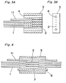
- Figures 3A and 3B show one embodiment of optical fiber connection according to the present invention, in which the same numerals represent the same elements as in Figures lA and 1B.
- the connector is to be used for connecting three optical fibers 1, it includes an additional coated optical fiber 11, which is cut at a predetermined length from the connector, for example, one meter.
- the connector is supplied in a form including such additional optical fiber 11 and used in place.
- Three optical fibers 1 of the connector are connected to three coated optical fibers while the additional optical fiber 11 is left unconnected.
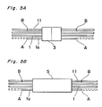
- each side of the fiber la is cut at the positions A and reconnected to the additional optical fiber 11 at the positions B.
- Figure 4 shows a generally fusion-spliced connection of three single core optical fibers 1 which connection is reinforced by a heat-shrinkable tube 5.
- This connection also includes an additional optical fiber 11, which is reinforced by the tube 5 in the same manner as the other optical fibers being reinforced. If one pair la of the connected optical fibers gives trouble, the fiber la is cut at the positions A and reconnected to the additional optical fiber 11 at the positions B as shown in Figure 5B.
- one additional optical fiber is used, although two or more additional optical fibers may be included in the connection within the scope of the present invention.
Landscapes
- Physics & Mathematics (AREA)
- General Physics & Mathematics (AREA)
- Optics & Photonics (AREA)
- Mechanical Coupling Of Light Guides (AREA)
Abstract
Description
- The present invention relates to an optical fiber connection.
- A typical conventional single core assembled type optical connector is shown in Figures lA and lB of the accompanying drawings, which are respectively a longitudinal section and a side elevation of the connector. In these Figures,
numeral 1 represents a coated optical fiber,numeral 2 represents an optical fiber,numeral 3 represents a ferule in which theoptical fiber 2 is positioned and fixed, andnumeral 4 represents a guide hole receiving pin for positioning the connectedferule 2. As shown in the Figures, the number of the optical fibers to be connected and that of the coated optical fibers installed in the connector are the same. Therefore, once one of the fibers in the connector should be damaged or broken in the assembling field, the connector should be reabrased in place, or the whole connector should be replaced, or all the fibers should be reconnected by means of coated optical connector fibers. - Figure 2 is a longitudinal section of a generally fusion-spliced connection of three single core coated
optical fibers 1 reinforced by a heat-shrinkable tube 5. In this Figure,numeral 2 represents a fusion spliced optical fiber,numeral 6 represents a reinforcement steel wire, andnumeral 7 represents a hot melt adhesive filling the gap between the fibers. With such fusion spliced connection, if one fiber is broken, all three fibers should be reconnected. - One object of the present invention is to provide an optical fiber connection which can overcome at least some drawbacks associated with the conventional optical fiber connections.
- Another object of the present invention is to provide an optical fiber connection which can cope with urgent repair of a broken optical fiber in the connection.
- According to the present invention, there is provided an optical fiber connection comprising at least one optical fiber to which a pair of coated optical fibers is connected and at least one additional optical fiber.
-
- Figures lA and 1B are a longitudinal section and a side elevation respectively of a conventional single core assembled type optical connector;
- Figure 2 is a longitudinal section of a generally fusion-spliced connection of three pairs of single core coated optical fibers which connection is reinforced by a heat-shrinkable tube;
- Figures 3A and 3B are a longitudinal section and a side elevation respectively of one embodiment of the optical fiber connection according to the present invention;
- Figure 4 is a longitudinal section of a generally fusion-spliced connection of three pairs of single core coated optical fiber wires according to a further embodiment of the present invention, which connection is reinforced by a heat-shrinkable tube; and
- Figures 5A and 5B show repaired connections.
- Figures 3A and 3B show one embodiment of optical fiber connection according to the present invention, in which the same numerals represent the same elements as in Figures lA and 1B. In this type of the connection, although the connector is to be used for connecting three
optical fibers 1, it includes an additional coatedoptical fiber 11, which is cut at a predetermined length from the connector, for example, one meter. The connector is supplied in a form including such additionaloptical fiber 11 and used in place. Threeoptical fibers 1 of the connector are connected to three coated optical fibers while the additionaloptical fiber 11 is left unconnected. - As shown in Figure 5A, if one pair la of the connected optical fibers gives trouble, each side of the fiber la is cut at the positions A and reconnected to the additional
optical fiber 11 at the positions B. - Figure 4 shows a generally fusion-spliced connection of three single core
optical fibers 1 which connection is reinforced by a heat-shrinkable tube 5. This connection also includes an additionaloptical fiber 11, which is reinforced by thetube 5 in the same manner as the other optical fibers being reinforced. If one pair la of the connected optical fibers gives trouble, the fiber la is cut at the positions A and reconnected to the additionaloptical fiber 11 at the positions B as shown in Figure 5B. - In the above description, one additional optical fiber is used, although two or more additional optical fibers may be included in the connection within the scope of the present invention.
- When five optical fibers are connected by means of an optical connector similar to that shown in Figure 1, and one of them is broken, it takes 2 or 3 hours to reconnect all five fibers with a new connector, or it takes at least one hour to replace the troubled connector with a Pigral type connector, since the fibers should be fusion-spliced. In contrast, when the connector including the additional optical fiber according to the present invention is used, only the broken fiber is to be reconnected to both ends of the additional fiber. This takes less than 30 minutes, which is one fourth to one sixth of that required in case of the conventional optical connector, and a half of that required with use of the Pigral type connector. While the repair of the fusion-spliced connection of five optical fibers takes about one hour by the conventional method, it takes less than 30 minutes according to the present invention.
Claims (6)
Applications Claiming Priority (2)
| Application Number | Priority Date | Filing Date | Title |
|---|---|---|---|
| JP59172614A JPS6150107A (en) | 1984-08-20 | 1984-08-20 | Optical fiber coupling part |
| JP172614/84 | 1984-08-20 |
Publications (3)
| Publication Number | Publication Date |
|---|---|
| EP0174524A2 true EP0174524A2 (en) | 1986-03-19 |
| EP0174524A3 EP0174524A3 (en) | 1987-08-12 |
| EP0174524B1 EP0174524B1 (en) | 1993-02-03 |
Family
ID=15945139
Family Applications (1)
| Application Number | Title | Priority Date | Filing Date |
|---|---|---|---|
| EP85110443A Expired - Lifetime EP0174524B1 (en) | 1984-08-20 | 1985-08-20 | Optical fiber connection |
Country Status (3)
| Country | Link |
|---|---|
| EP (1) | EP0174524B1 (en) |
| JP (1) | JPS6150107A (en) |
| DE (1) | DE3587059T2 (en) |
Families Citing this family (1)
| Publication number | Priority date | Publication date | Assignee | Title |
|---|---|---|---|---|
| JPH0660967B2 (en) * | 1987-02-06 | 1994-08-10 | 住友電気工業株式会社 | Optical fiber all-in-one fusion splicing method |
Citations (8)
| Publication number | Priority date | Publication date | Assignee | Title |
|---|---|---|---|---|
| DE2446152A1 (en) * | 1974-09-27 | 1976-04-15 | Licentia Gmbh | ADJUSTABLE COUPLING ARRANGEMENT FOR CONNECTING AND ALIGNMENT OF AT LEAST TWO LIGHT WAVE GUIDES OF AN OPTICAL MESSAGE TRANSFER SYSTEM ON A COMMON OPTICAL AXIS |
| US4083625A (en) * | 1976-08-02 | 1978-04-11 | Corning Glass Works | Optical fiber junction device |
| DE2842077A1 (en) * | 1978-09-27 | 1980-04-10 | Siemens Ag | Optical waveguide cable contg. safety monitoring fibre - which exhibits pronounced increase in attenuation if unauthorised tapping of cable occurs |
| JPS5784405A (en) * | 1980-11-13 | 1982-05-26 | Nippon Telegr & Teleph Corp <Ntt> | Optical cable for urgent rehabilitation and optical cable urgent rehabilitation executing method using said cable |
| EP0081349A1 (en) * | 1981-12-03 | 1983-06-15 | Xerox Corporation | Terminations for optical fibers |
| EP0109648A1 (en) * | 1982-11-15 | 1984-05-30 | Hitachi, Ltd. | Flat type plastic connector means for splicing a plurality of optical fibres |
| EP0131131A1 (en) * | 1983-05-31 | 1985-01-16 | Alcatel Cit | Optical spatial switching arrangement |
| EP0164784A1 (en) * | 1984-05-23 | 1985-12-18 | Koninklijke Philips Electronics N.V. | Method of interconnecting optical fibres |
Family Cites Families (1)
| Publication number | Priority date | Publication date | Assignee | Title |
|---|---|---|---|---|
| JPS6129809A (en) * | 1984-07-20 | 1986-02-10 | Dainichi Nippon Cables Ltd | Connector for optical fiber |
-
1984
- 1984-08-20 JP JP59172614A patent/JPS6150107A/en active Pending
-
1985
- 1985-08-20 EP EP85110443A patent/EP0174524B1/en not_active Expired - Lifetime
- 1985-08-20 DE DE8585110443T patent/DE3587059T2/en not_active Expired - Fee Related
Patent Citations (8)
| Publication number | Priority date | Publication date | Assignee | Title |
|---|---|---|---|---|
| DE2446152A1 (en) * | 1974-09-27 | 1976-04-15 | Licentia Gmbh | ADJUSTABLE COUPLING ARRANGEMENT FOR CONNECTING AND ALIGNMENT OF AT LEAST TWO LIGHT WAVE GUIDES OF AN OPTICAL MESSAGE TRANSFER SYSTEM ON A COMMON OPTICAL AXIS |
| US4083625A (en) * | 1976-08-02 | 1978-04-11 | Corning Glass Works | Optical fiber junction device |
| DE2842077A1 (en) * | 1978-09-27 | 1980-04-10 | Siemens Ag | Optical waveguide cable contg. safety monitoring fibre - which exhibits pronounced increase in attenuation if unauthorised tapping of cable occurs |
| JPS5784405A (en) * | 1980-11-13 | 1982-05-26 | Nippon Telegr & Teleph Corp <Ntt> | Optical cable for urgent rehabilitation and optical cable urgent rehabilitation executing method using said cable |
| EP0081349A1 (en) * | 1981-12-03 | 1983-06-15 | Xerox Corporation | Terminations for optical fibers |
| EP0109648A1 (en) * | 1982-11-15 | 1984-05-30 | Hitachi, Ltd. | Flat type plastic connector means for splicing a plurality of optical fibres |
| EP0131131A1 (en) * | 1983-05-31 | 1985-01-16 | Alcatel Cit | Optical spatial switching arrangement |
| EP0164784A1 (en) * | 1984-05-23 | 1985-12-18 | Koninklijke Philips Electronics N.V. | Method of interconnecting optical fibres |
Non-Patent Citations (2)
| Title |
|---|
| Handbook of Optics, Fibre Optics and Lightwave communications Vocabulary * |
| PATENT ABSTRACTS OF JAPAN, vol. 6, no. 166 (P-138)[1044], 31st August 1982; & JP-A-57 084 405 (NIPPON DENSHIN DENWA KOSHA) 26-05-1982 * |
Also Published As
| Publication number | Publication date |
|---|---|
| DE3587059D1 (en) | 1993-03-18 |
| EP0174524A3 (en) | 1987-08-12 |
| EP0174524B1 (en) | 1993-02-03 |
| JPS6150107A (en) | 1986-03-12 |
| DE3587059T2 (en) | 1993-07-15 |
Similar Documents
| Publication | Publication Date | Title |
|---|---|---|
| EP0146405B1 (en) | End plug for a fiber optic in-line splice case assembly | |
| CA2190405C (en) | Fibre optic cable connector | |
| US4812008A (en) | Method and apparatus for connecting optical fibers | |
| WO1996031795A1 (en) | A field installable optical fiber connector and an associated method of fabrication | |
| JPH01223404A (en) | Optical fiber connector and optical fiber, connection and termination thereof and manufacture of plug | |
| US4431261A (en) | Fiber optic splitter | |
| US6767136B1 (en) | Device having multiple optical fibers | |
| JPH03100603A (en) | Method of manufacturing fused optical fiber coupler | |
| JP2003302561A (en) | Optical fiber component and method for manufacturing the same | |
| US6728452B2 (en) | Optical cable, method of installing optical cable, and optical transmission line | |
| EP0491366A1 (en) | Optical fiber cable | |
| EP0277390B1 (en) | Assembly comprising a planar optical circuit and an optical fibre coupled thereto | |
| EP0174524A2 (en) | Optical fiber connection | |
| EP0184432A2 (en) | Optical coupler | |
| CN114522856A (en) | Method for manufacturing branch optical fiber connector | |
| EP0146404B1 (en) | Fibre optic in-line splice case assembly | |
| US6217233B1 (en) | Restoration splice method and apparatus | |
| US4793674A (en) | Fiber optic coupler using frit | |
| JPH07270639A (en) | Connecting method for coated fiber of optical fiber ribbon | |
| JPS59109012A (en) | Optical multiconnector | |
| EP1390785B1 (en) | Optical cables and methods of repairing damaged optical cable installations | |
| JP4062110B2 (en) | OPTICAL CONNECTION COMPONENT, OPTICAL CONNECTION METHOD, AND OPTICAL COMMUNICATION DEVICE | |
| US6494625B1 (en) | Color-coded restoration splice block | |
| JPS6365412A (en) | Connector for optical fiber | |
| JPS5926710A (en) | Method for connecting connector of optical fiber |
Legal Events
| Date | Code | Title | Description |
|---|---|---|---|
| PUAI | Public reference made under article 153(3) epc to a published international application that has entered the european phase |
Free format text: ORIGINAL CODE: 0009012 |
|
| AK | Designated contracting states |
Kind code of ref document: A2 Designated state(s): DE FR GB IT SE |
|
| PUAL | Search report despatched |
Free format text: ORIGINAL CODE: 0009013 |
|
| AK | Designated contracting states |
Kind code of ref document: A3 Designated state(s): DE FR GB IT SE |
|
| 17P | Request for examination filed |
Effective date: 19871221 |
|
| 17Q | First examination report despatched |
Effective date: 19890920 |
|
| GRAA | (expected) grant |
Free format text: ORIGINAL CODE: 0009210 |
|
| AK | Designated contracting states |
Kind code of ref document: B1 Designated state(s): DE FR GB IT SE |
|
| ITF | It: translation for a ep patent filed |
Owner name: JACOBACCI CASETTA & PERANI S.P.A. |
|
| REF | Corresponds to: |
Ref document number: 3587059 Country of ref document: DE Date of ref document: 19930318 |
|
| ET | Fr: translation filed | ||
| PLBE | No opposition filed within time limit |
Free format text: ORIGINAL CODE: 0009261 |
|
| STAA | Information on the status of an ep patent application or granted ep patent |
Free format text: STATUS: NO OPPOSITION FILED WITHIN TIME LIMIT |
|
| 26N | No opposition filed | ||
| EAL | Se: european patent in force in sweden |
Ref document number: 85110443.0 |
|
| PGFP | Annual fee paid to national office [announced via postgrant information from national office to epo] |
Ref country code: SE Payment date: 19980806 Year of fee payment: 14 |
|
| PGFP | Annual fee paid to national office [announced via postgrant information from national office to epo] |
Ref country code: GB Payment date: 19980811 Year of fee payment: 14 |
|
| PGFP | Annual fee paid to national office [announced via postgrant information from national office to epo] |
Ref country code: FR Payment date: 19980814 Year of fee payment: 14 |
|
| PGFP | Annual fee paid to national office [announced via postgrant information from national office to epo] |
Ref country code: DE Payment date: 19980831 Year of fee payment: 14 |
|
| PG25 | Lapsed in a contracting state [announced via postgrant information from national office to epo] |
Ref country code: GB Free format text: LAPSE BECAUSE OF NON-PAYMENT OF DUE FEES Effective date: 19990820 |
|
| PG25 | Lapsed in a contracting state [announced via postgrant information from national office to epo] |
Ref country code: SE Free format text: THE PATENT HAS BEEN ANNULLED BY A DECISION OF A NATIONAL AUTHORITY Effective date: 19990830 |
|
| GBPC | Gb: european patent ceased through non-payment of renewal fee |
Effective date: 19990820 |
|
| PG25 | Lapsed in a contracting state [announced via postgrant information from national office to epo] |
Ref country code: FR Free format text: LAPSE BECAUSE OF NON-PAYMENT OF DUE FEES Effective date: 20000428 |
|
| EUG | Se: european patent has lapsed |
Ref document number: 85110443.0 |
|
| PG25 | Lapsed in a contracting state [announced via postgrant information from national office to epo] |
Ref country code: DE Free format text: LAPSE BECAUSE OF NON-PAYMENT OF DUE FEES Effective date: 20000601 |
|
| REG | Reference to a national code |
Ref country code: FR Ref legal event code: ST |