EP0169324A1 - Switching protocol with retry - Google Patents
Switching protocol with retry Download PDFInfo
- Publication number
- EP0169324A1 EP0169324A1 EP85106041A EP85106041A EP0169324A1 EP 0169324 A1 EP0169324 A1 EP 0169324A1 EP 85106041 A EP85106041 A EP 85106041A EP 85106041 A EP85106041 A EP 85106041A EP 0169324 A1 EP0169324 A1 EP 0169324A1
- Authority
- EP
- European Patent Office
- Prior art keywords
- user
- retry
- requests
- connection
- switching
- Prior art date
- Legal status (The legal status is an assumption and is not a legal conclusion. Google has not performed a legal analysis and makes no representation as to the accuracy of the status listed.)
- Granted
Links
Images


Classifications
-
- G—PHYSICS
- G06—COMPUTING; CALCULATING OR COUNTING
- G06F—ELECTRIC DIGITAL DATA PROCESSING
- G06F15/00—Digital computers in general; Data processing equipment in general
- G06F15/16—Combinations of two or more digital computers each having at least an arithmetic unit, a program unit and a register, e.g. for a simultaneous processing of several programs
- G06F15/163—Interprocessor communication
- G06F15/173—Interprocessor communication using an interconnection network, e.g. matrix, shuffle, pyramid, star, snowflake
- G06F15/17356—Indirect interconnection networks
- G06F15/17368—Indirect interconnection networks non hierarchical topologies
- G06F15/17375—One dimensional, e.g. linear array, ring
-
- H—ELECTRICITY
- H04—ELECTRIC COMMUNICATION TECHNIQUE
- H04L—TRANSMISSION OF DIGITAL INFORMATION, e.g. TELEGRAPHIC COMMUNICATION
- H04L12/00—Data switching networks
Definitions
- the invention relates to a protocol with retry for a switching system using multiple, autonomous planes of cross-point switches.
- FIG. 1 For background, reference is made to our copending European Patent Application , entitled “Switching System” (US Serial No. 624881, Y09-83-142). That patent application discloses a switching system, illustrated in Figure 1 hereto, for selectively providing point-to-point communication paths between for example users 10 and 12.
- An adaptor 14 is associated with each user 10 and is connected.to it by an internal memory bus 16.
- the adaptor 14 divides a message on the internal memory bus 16 into a number of parallel paths. Each path is defined by an output line 18, 20 and 22.
- Each output line is associated with a parallel input line 24, 26 and 28 to form pairs of full-duplex lines.
- Each pair of input and output lines 18 and 24, 20 and 26, or 22 and 28 are connected to a different cross-point switch 30, 32 and 34 in a central switch 36. Only three sets of full-duplex lines and three cross-point switches are shown in Figure 1 but any number equal to or greater than two is possible. In a further embodiment there may be a greater number g of full- duplex lines between the adaptor 14 and the individual switches 30, 32 and 34.
- Each adaptor 14 not only can divide a message from the internal memory bus 16 onto the parallel output lines 18, 20 and 22 but can also recombine messages that it receives on parallel input lines 24, 26 and 28 into a recombined message on the internal memory bus 16.
- a user 10 wishes to communicate with another user 12, its adaptor 14 simultaneously instructs all the cross-point switches 30, 32 and 34 to make the proper connections to the input and output lines of the adaptor of the other user 12.
- parallel communication paths are established between the two users 10 and 12.
- the total bandwidth of the parallel communication path is thus not limited to the bandwidth of a single duplex line or of a single cross-point switch. Instead, the limiting bandwidth of the duplex line 18 and 24 or of the cross-point switch 30 is multiplied by the number of parallel paths.
- each adaptor 14 is to issue controls to each of the cross-point switches 30, 32 and 34 to make the proper connections and disconnections. These commands are carried on the same output lines 18, 20 and 22 that are used for the subsequently transmitted parallel message.
- the previously described patent application discloses a fast and efficient protocol for the connection and disconnection commands. The protocol must be followed for all the cross-point switches 30, 32 and 34 in the central switch 36 that are being used for the parallel communication paths. It is assumed that the cross-point switches 30, 32 and 34 are independent of each other so that a command issued to one cross-point switch has no effect upon the other cross-point switches in the central switch 36.
- n simultaneous commands for connection must be issued by the requesting adaptor 14. It has previously been assumed that all n requests would either be all sucessful or all unsucessful. An unsuccessful request would result when the user to which the connection is requested is already busy, that is, its input and output lines are already connected to still another user.
- the switching system of Figure 1 is intended to be operated at very high switching rates and the simultaneity of parallel commands issuing from a single adaptor is no guarantee that the commands will be simultaneously received at all the cross-point switches 30, 32 and 34.
- the invention in its preferred form can be summarized as a protocol for accomplishing simultaneous connections through a plurality of autonomous switching planes.
- a user issues a connection command to all of the planes.
- the user is notified by each of the planes if a connection has been successfully made. If all the connections have not been made, the user issues a retry request to resolve the conflict with other users that have attempted to make conflicting connections.
- the retry request may be of three separate forms.
- the user that has established a connection in a particular plane can issue a retry request that overrides already established connections in the remaining planes.
- the user that has established connections through a majority of the planes issues a retry request that likewise overrides the connections already established in the remaining planes.
- all users issue retry requests.
- the switching planes receive the retry request and according to a priority scheme among the users accept a higher priority retry request than the conflicting connection and reject a lower priority one.
- the user establishes simultaneous communication paths through the multiple autonomous switching planes by the use of three commands CONNECT, DISCONNECT and RETRY.
- CONNECT the first two of these, CONNECT and DISCONNECT are described in the co-pending and previously cited patent application. That explanation is repeated here because of their integral relationship with the new command RETRY.
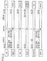
- the switching protocol assumes several limitations upon the structure of the central switch and the serial links 18-28. First of all, it is assumed that all data transfer is accomplished by a request/response sequence, that is, that one user requests another user to respond. Prior to the request, there is no connection between the user, and, after the response, the connection is broken. It is further assumed that each adaptor has two serial links to each of the switching planes, one for transmitting and one for receiving. These two links can be considered as a full-duplex link. It is further assumed that the adaptors are continuously broadcasting and receiving at some fixed repetition rate. This continuous broadcasting is illustrated in Fig. 2 for two users A and B connected through the switching system.
- both user A and user B are periodically transmitting a characteristic control word C followed by the identification of the transmitting user.
- the idle transmission can include a clock synchronization signal (010101 etc.) for achieving clock synchronization between two subsystems. Because the switch reflects these signals back to the transmitting user, after a progation time, both user A and user B receive their own idle transmissions.
- the connect frame consists of the first byte C indicating a request for a connection at the switch.
- the connect control character C 2 is followed by the identification B of the requested destination user.
- the connect frame finishes up with a clock synchronization sequence (010101 etc.) and then idle characters.
- the connect frame is equivalent to a CONNECT (A,B) command.
- Following the connect frame is a data frame containing data which is delimited at both the beginning and the end by delimiting characters C .
- the data in the data frame provides the information for the receiving user B to respond to.
- connection through the switch it can be accomplished in 50 ns, allowing the following data frame to be transmitted through the switch to the receiving user B. If however the connection cannot be made, for example, because user B is busy and its busy bit is 1, no change in connection is made and the transmitting user A receives back its own connect and data frames. If the connection is successfully made, the transmitting user A receives instead the idle transmission C 1 B of the station to which it is transmitting, thus confirming the connection.
- the receiving user B Once the receiving user B has received the request, it must spend some time processing this request. During the processing time, user B continues to broadcast its idle code C I B which is received by the originally requesting user A. A clock synchronization signal in the idle transmission would synchronize the clock of A with the clock of B. This user A is in a wait state awaiting the response and is also continuing to transmit its idle sequence of C 1 A, which is transmitted to the other user B.
- the user B proceeds to transmit the data delimited on the forward end by a delimiter C 3 and delimited on the trailing end by the control character C 2 .
- the control character C 2 was previously used as a connect control character, it also indicates to an already connected cross-point that the cross-point is to be disconnected.
- the data is transmitted in the delimited packet and may be of substantial length, for instance 132 bytes. This data is the response to the original request and is received by the requesting user A. During the time of the data transmission, the user A continues to broadcast its idle sequence C I A.
- the cross-point connecting user A to user B is disconnected.
- the user B then recommences sending its idle sequence G 1 B which is reflected back to user B by the switch.
- the user A which has continued to transmit its idle sequence C 1 A during the data reception, sends out a disconnect control character C 2 to insure the disconnection at the switch.
- a disconnect control character C 2 to insure the disconnection at the switch.
- the user A begins to receive its own idle code C 1 A, it has confirmed this disconnection at the cross-point switch.
- Either of the disconnect control sequences can be considered as the DISCONNECT (A,B) command.
- the above protocol is really the protocol for a single plane. Similar commands must be simultaneously issued to all the planes and the above description assumes that all the connections and disconnections were in fact simultaneously performed on all the planes. However, as previously described, the situation can arise where a CONNECT (A, B) was successfully completed on one plane but was unsuccessful on another plane.
- the adaptor 14 is divided, as illustrated in Fig. 3, into an adaptor controller 40 and separate mini-adaptors 42 and 44.
- the adaptor controller 40 receives a message on the internal memory bus 16 and divides it between the mini-adaptors 42 and 44.
- Each mini-adaptor 42 or 44 sends its part of the divided message on the output link 18 or 20 and receives the divided message on the input link 24 or 26.
- Each mini-adaptor 42 or 46 is connected by the serial links to a separate autonomous cross-point switch. If g is greater than 1, there is a corresponding increase in the number of input and output links connected to each mini-adaptor.
- each mini-adaptor sends out the connection request on its output link 18 or 20.
- the protocol of Fig. 2 applies to each of the mini-adaptors 42 and 44.
- the protocol assures that the mini- adaptors are notified of the success or the lack of success for their respective request. This information is conveyed to the adaptor controller 40.
- the adaptor controller 40 After the adaptor controller 40 has caused the mini-adaptors to transmit the simultaneous connection requests to the individual autonomous planes, it waits a predetermined time T to receive confirmation of the n requests. If all n requests have been granted, the switch set-up is complete and processing continues. If none of the requests have been granted, the adaptor waits for a random delay time TO to reinitiate the switch set-up, that is, to again cause all the mini-adaptors 42 and 44 to issue their connect command. However, if after the predetermined time T only some of the end cross-point connections have been granted, then a contention resolution is required because some of the necessary paths have been blocked by a conflicting request from another adaptor.
- the conflict can arise in a number of different ways. For example, if the central switch has received two nearly simultaneous commands CONNECT (A, B) and CONNECT (C, B), then the users A and C are both requesting access to the user B and each requires all n ports to user B. Because of the autonomous nature of the n cross-point switches, some of the ports were connected to user A and some to the user C and neither user A nor user C is successfully and completely connected. Another situation arises when the users A and B are nearly simultaneously requesting connection to each other, that is, the command CONNECT (A, B) overlaps the command CONNECT (B, A).
- a third type of conflict arises when the user A is requesting a connection to the user B at the same time that the user B is requesting connection to a third user C, that is, the conflict between CONNECT (A, B) with CONNECT (B, C).
- CONNECT A, B
- CONNECT C, D
- CONNECT B, C
- the adaptor controller 40 follows a conflict protocol to cause the mini-adaptors 42 which have not been successfully connected because of a conflict to issue RETRY commands in an effort to complete the full set of connections in the autonomous cross-point switches 30-34.
- the separate cross-point switches 30-34 receive the RETRY commands and, following the protocol, override a previously made connection or cross-point in order to grant at least one of the RETRY commands.
- the RETRY command differs from the CONNECT command in that the CONNECT (A, B) command is successfully executed only if the cross-point (A, B) is available. In the previously described controller, this availability is indicated by the busy bit for B being 0.
- the RETRY (A, B) is granted access by the conflict protocol, the connection between A and B is made despite the fact that the busy bit for B is 1, indicating that B is already busy. That is, the RETRY command can override an already existing connection.
- the conflict protocol can be implemented in at least three ways.
- one of the switching planes or cross-point switches 30-34 is specified as determining the winner, for example, cross-point 30.
- the adaptor controller 40 determines if the CONNECT command issued to the specified cross-point switch 30 was successfully granted. If the CONNECT command to the specified cross-point 30 was granted, the adaptor controller 40 causes RETRY commands to be issued by all of its mini-adaptors 42 and 44 that have been unsuccessful because of conflict, that is, that have not been connected because of the conflict. If the CONNECT command to the specified cross-point switch 30 was not successfully granted, the adaptor controller 40 does not cause any RETRY commands to be issued. Thus one and only one adaptor will issue RETRY commands.
- any cross-point switch 30-34 receiving a RETRY command honors the command and overrides any existing connections.
- the winning adaptor completes its connections through all the planes of the central switch 36 and the losing adaptors are disconnected by the RETRY commands of the winning adaptor.
- a second way of implementing the conflict protocol is similar to the first implementation except that the winning adaptor is the one that has successfully been connected through more than half of the cross-point switches 30-34.
- the winning adaptor then issues the necessary RETRY commands to complete its own connections and to disconnect the losing adaptors.
- This way of implementing the conflict protocol has the disadvantage that when two adaptors have each successfully made connections on exactly half of the cross-point switches, there is no defined winner.
- a conflict can possibly involve only a single CONNECT request. If a CONNECT request overlaps a DISCONNECT request that disconnects the ports requested by the CONNECT, connections may be successfully completed on only some of the planes, while the remaining planes become available somewhat later, but nonetheless too late. In this situation, as well as the situations described above, there may be no winner in the first two ways of implementing the conflict protocol.
- a method of escaping the no-winner situation is to have the losing adaptor monitor the connection clock signals on its successfully completed connections. If there is a winner, the connection clock signals will be terminated by the winner's RETRY command disconnecting the losing adaptor. However, if after the elapse of a time-out period after the start of the conflict, the connection clock signals continue, the losing adaptor sends DISCONNECT commands to the connected switching planes involved in the conflict to end the no-winner situation.
- the adaptor controller 40 upon detecting a conflict situation, causes all of its mini-adaptors 42 and 44 that have been unsuccessful because of conflict, that is, have not been connected because of conflict, to issue RETRY commands. Since at least two adaptors are in conflict (discounting the CONNECT/DISCONNECT overlap situation), more than one set of RETRY commands will be issued by the various adaptors. No priority is relied upon in issuing the RETRY commands. However, each adaptor is assigned 4 n address and the addresses are arranged in a sequential priority scheme, e.g. A has priority over B and other lower priority adaptors, B has priority over C and other lower priority adaptors, etc.
- the controllers on the autonomous switching planes are programmed with the address priority scheme.
- the switching plane controller receives a RETRY request from an adaptor, it determines the priority of the requesting adaptor against the priority of the adaptor that caused the conflicting connection to be made. If the requesting adaptor has a higher priority, the RETRY request overrides the existing connection. If the requesting adaptor has a lower priority, the RETRY request is rejected by the switch. As a result the higher priority adaptor in conflict will complete the missing connections while the lower priority adaptor will lose its already existing connections by a higher priority RETRY. Eventually a complete set of connections are made.
- each plane receives one RETRY request. If the RETRY request is from A, and the port to B is requested by A but is currently held by C, the switch determines that A has a higher priority than C and so honors the RETRY (A,B) request. However the RETRY (C,B) request would be refused in view of the facts that B is currently held by A and that A outranks C.
- a source adaptor is the adaptor making a request for connection to a destination adaptor.
- the priority of the source adaptor making the RETRY request is compared with the priority of the source adaptor causing the conflict.
- CONNECT B,C
- CONNECT C,A
- RETRY B,C
- CONNECT C,A
- RETRY C, A
- the protocol shown in Fig. 2 provides that the CONNECT and RETRY commands are implemented as connect and retry frames that are immediately followed by data frames.
- data can be quickly transmitted through the switch.
- parallel data frames may arrive at the destination adaptor from at least two source adaptors.
- an additional data frame will be transmitted through the overridden cross-point.
- the destination adaptor need to have the means to recognize when it has received a complete set of data frames from a single source adaptor and furthermore must have the buffering capabilities to handle more than one data frame on a single input line before recombining one of those data frames with the proper parallel data frames.
- the source recognition could be based on the data frame containing a source identifier. Only when the destination adaptor has received parallel data frames from the same source adaptor would it consider the data to be received, that is, proceed to the merging of the data frames and processing that data.
Landscapes
- Engineering & Computer Science (AREA)
- Physics & Mathematics (AREA)
- Theoretical Computer Science (AREA)
- Computer Hardware Design (AREA)
- General Physics & Mathematics (AREA)
- General Engineering & Computer Science (AREA)
- Software Systems (AREA)
- Mathematical Physics (AREA)
- Computer Networks & Wireless Communication (AREA)
- Signal Processing (AREA)
- Communication Control (AREA)
- Exchange Systems With Centralized Control (AREA)
- Data Exchanges In Wide-Area Networks (AREA)
- Use Of Switch Circuits For Exchanges And Methods Of Control Of Multiplex Exchanges (AREA)
Abstract
Description
- The invention relates to a protocol with retry for a switching system using multiple, autonomous planes of cross-point switches.
- For background, reference is made to our copending European Patent Application , entitled "Switching System" (US Serial No. 624881, Y09-83-142). That patent application discloses a switching system, illustrated in Figure 1 hereto, for selectively providing point-to-point communication paths between for
example users adaptor 14 is associated with eachuser 10 and is connected.to it by aninternal memory bus 16. Theadaptor 14 divides a message on theinternal memory bus 16 into a number of parallel paths. Each path is defined by anoutput line parallel input line output lines different cross-point switch central switch 36. Only three sets of full-duplex lines and three cross-point switches are shown in Figure 1 but any number equal to or greater than two is possible. In a further embodiment there may be a greater number g of full- duplex lines between theadaptor 14 and theindividual switches - The remaining users such as
user 12 have a similar adaptor and similar full-duplex lines to the individual cross-point switches. Eachadaptor 14 not only can divide a message from theinternal memory bus 16 onto theparallel output lines parallel input lines internal memory bus 16. - If a
user 10 wishes to communicate with anotheruser 12, itsadaptor 14 simultaneously instructs all thecross-point switches other user 12. Thereby, parallel communication paths are established between the twousers duplex line cross-point switch 30 is multiplied by the number of parallel paths. - A roughly analogous communication system is described in U.S. Patent 4,015,204 to Miyazawa in which data are switched into parallel registers which are then used to modulate different carrier frequencies on a single transmission line. Wide band switching is itself a known idea, as discussed by Teraslinna in U.S. Patent 4,402,008. Parallel planes of circuits for either storage or switching have been described by Mansuetto et al in U.S. Patent 3,321,745 and by Burns in U.S. Patent 3,355,721.
- One of the functions of each
adaptor 14 is to issue controls to each of thecross-point switches same output lines cross-point switches central switch 36 that are being used for the parallel communication paths. It is assumed that the cross-point switches 30, 32 and 34 are independent of each other so that a command issued to one cross-point switch has no effect upon the other cross-point switches in thecentral switch 36. - Thus if there are n
cross-point switches adaptor 14. It has previously been assumed that all n requests would either be all sucessful or all unsucessful. An unsuccessful request would result when the user to which the connection is requested is already busy, that is, its input and output lines are already connected to still another user. However, the switching system of Figure 1 is intended to be operated at very high switching rates and the simultaneity of parallel commands issuing from a single adaptor is no guarantee that the commands will be simultaneously received at all thecross-point switches central switch 36 are likely to be performed at slightly varying times depending upon the delays introduced by separate output lines and the control circuitry within the individual cross-point switches. Furthermore, there is no master clock but instead different clocks control the switching functions on each plane. As a result, if two users are simultaneously attempting to make a connection to a single third user, there is a probability that some connections will be made for the first user and some for the second user. Neither user would have established a complete set of parallel connection with the desired destination user. - Accordingly, it is an object of this invention to provide a method for establishing parallel connections in multiple cross-point switches between two users.
- It is a further object of this invention to provide a method of resolving a conflict when two or more users attempt to make conflicting connections to another user.
- The invention in its preferred form can be summarized as a protocol for accomplishing simultaneous connections through a plurality of autonomous switching planes. A user issues a connection command to all of the planes. The user is notified by each of the planes if a connection has been successfully made. If all the connections have not been made, the user issues a retry request to resolve the conflict with other users that have attempted to make conflicting connections. The retry request may be of three separate forms. The user that has established a connection in a particular plane can issue a retry request that overrides already established connections in the remaining planes. In another form, the user that has established connections through a majority of the planes issues a retry request that likewise overrides the connections already established in the remaining planes. In a third form, all users issue retry requests. The switching planes receive the retry request and according to a priority scheme among the users accept a higher priority retry request than the conflicting connection and reject a lower priority one.
-
- Fig. 1 is a block diagram of the multi-plane switching system to which the present invention can be applied.
- Fig. 2 is a timing diagram for the protocol of this invention.
- Fig. 3 is a block diagram of an adaptor for use with this invention.
- In the present invention, the user establishes simultaneous communication paths through the multiple autonomous switching planes by the use of three commands CONNECT, DISCONNECT and RETRY. The first two of these, CONNECT and DISCONNECT are described in the co-pending and previously cited patent application. That explanation is repeated here because of their integral relationship with the new command RETRY.
- The switching protocol assumes several limitations upon the structure of the central switch and the serial links 18-28. First of all, it is assumed that all data transfer is accomplished by a request/response sequence, that is, that one user requests another user to respond. Prior to the request, there is no connection between the user, and, after the response, the connection is broken. It is further assumed that each adaptor has two serial links to each of the switching planes, one for transmitting and one for receiving. These two links can be considered as a full-duplex link. It is further assumed that the adaptors are continuously broadcasting and receiving at some fixed repetition rate. This continuous broadcasting is illustrated in Fig. 2 for two users A and B connected through the switching system. If user A is not otherwise connected through the switch, the switch connects the input from the user A to the output back to user A. Similarly, the output from user B is connected to its own input if the two serial links are not otherwise used. In the idle mode, as illustrated in Fig. 2, both user A and user B are periodically transmitting a characteristic control word C followed by the identification of the transmitting user. As explained later, the idle transmission can include a clock synchronization signal (010101 etc.) for achieving clock synchronization between two subsystems. Because the switch reflects these signals back to the transmitting user, after a progation time, both user A and user B receive their own idle transmissions.
- If user A wishes to trasmit a request to user B, user A transmits first an 8 byte data frame. The connect frame consists of the first byte C indicating a request for a connection at the switch. The connect control character C2 is followed by the identification B of the requested destination user. The connect frame finishes up with a clock synchronization sequence (010101 etc.) and then idle characters. The connect frame is equivalent to a CONNECT (A,B) command. Following the connect frame is a data frame containing data which is delimited at both the beginning and the end by delimiting characters C . The data in the data frame provides the information for the receiving user B to respond to.
- Our European patent application 84111283.2 describes a very fast, pipelined marking and unmarking procedure. When a connection request is received by the cross-point switch, the request is queued for processing by the switch controller. The controller uses a first-come, first-serve discipline. The controller contains a port connection table with a busy bit associated with every meaningfully connected port. When a connection to a port is processed, its busy bit is queried. If the busy bit of B is 0, i.e. idle, the busy bits of A and B are set to 1 and then the request is successfully granted by marking the cross-points at both (A, B) and (B, A). It is believed that if the connection through the switch is available, it can be accomplished in 50 ns, allowing the following data frame to be transmitted through the switch to the receiving user B. If however the connection cannot be made, for example, because user B is busy and its busy bit is 1, no change in connection is made and the transmitting user A receives back its own connect and data frames. If the connection is successfully made, the transmitting user A receives instead the idle transmission C1B of the station to which it is transmitting, thus confirming the connection.
- Once the receiving user B has received the request, it must spend some time processing this request. During the processing time, user B continues to broadcast its idle code CIB which is received by the originally requesting user A. A clock synchronization signal in the idle transmission would synchronize the clock of A with the clock of B. This user A is in a wait state awaiting the response and is also continuing to transmit its idle sequence of C1A, which is transmitted to the other user B.
- Once the user B has had sufficient time to process the request for data, it proceeds to transmit the data delimited on the forward end by a delimiter C3 and delimited on the trailing end by the control character C2. Although the control character C2 was previously used as a connect control character, it also indicates to an already connected cross-point that the cross-point is to be disconnected. The data is transmitted in the delimited packet and may be of substantial length, for instance 132 bytes. This data is the response to the original request and is received by the requesting user A. During the time of the data transmission, the user A continues to broadcast its idle sequence CIA.
- After the data packet has passed through the switch, the cross-point connecting user A to user B is disconnected. The user B then recommences sending its idle sequence G1B which is reflected back to user B by the switch. The user A, which has continued to transmit its idle sequence C1A during the data reception, sends out a disconnect control character C2 to insure the disconnection at the switch. When the user A begins to receive its own idle code C1A, it has confirmed this disconnection at the cross-point switch. Either of the disconnect control sequences can be considered as the DISCONNECT (A,B) command.
- The above protocol is really the protocol for a single plane. Similar commands must be simultaneously issued to all the planes and the above description assumes that all the connections and disconnections were in fact simultaneously performed on all the planes. However, as previously described, the situation can arise where a CONNECT (A, B) was successfully completed on one plane but was unsuccessful on another plane.
- The
adaptor 14 is divided, as illustrated in Fig. 3, into anadaptor controller 40 and separate mini-adaptors 42 and 44. Theadaptor controller 40 receives a message on theinternal memory bus 16 and divides it between the mini-adaptors 42 and 44. Each mini-adaptor 42 or 44 sends its part of the divided message on theoutput link input link output link adaptor controller 40. After theadaptor controller 40 has caused the mini-adaptors to transmit the simultaneous connection requests to the individual autonomous planes, it waits a predetermined time T to receive confirmation of the n requests. If all n requests have been granted, the switch set-up is complete and processing continues. If none of the requests have been granted, the adaptor waits for a random delay time TO to reinitiate the switch set-up, that is, to again cause all the mini-adaptors 42 and 44 to issue their connect command. However, if after the predetermined time T only some of the end cross-point connections have been granted, then a contention resolution is required because some of the necessary paths have been blocked by a conflicting request from another adaptor. - The conflict can arise in a number of different ways. For example, if the central switch has received two nearly simultaneous commands CONNECT (A, B) and CONNECT (C, B), then the users A and C are both requesting access to the user B and each requires all n ports to user B. Because of the autonomous nature of the n cross-point switches, some of the ports were connected to user A and some to the user C and neither user A nor user C is successfully and completely connected. Another situation arises when the users A and B are nearly simultaneously requesting connection to each other, that is, the command CONNECT (A, B) overlaps the command CONNECT (B, A). The contention in this conflict is not for the cross-points or for the ports but rather for which of the two users A and B controls those cross-point switches or ports according to the protocol of Fig. 2. A third type of conflict arises when the user A is requesting a connection to the user B at the same time that the user B is requesting connection to a third user C, that is, the conflict between CONNECT (A, B) with CONNECT (B, C). There are more complex conflicts that may arise when more than two connection commands overlap, for example, the conflict among CONNECT (A, B), CONNECT (C, D) and CONNECT (B, C).
- According to the invention, once the
adaptor controller 40 has determined that a conflict exists, it follows a conflict protocol to cause the mini-adaptors 42 which have not been successfully connected because of a conflict to issue RETRY commands in an effort to complete the full set of connections in the autonomous cross-point switches 30-34. The separate cross-point switches 30-34 receive the RETRY commands and, following the protocol, override a previously made connection or cross-point in order to grant at least one of the RETRY commands. The RETRY command differs from the CONNECT command in that the CONNECT (A, B) command is successfully executed only if the cross-point (A, B) is available. In the previously described controller, this availability is indicated by the busy bit for B being 0. On the other hand, if the RETRY (A, B) is granted access by the conflict protocol, the connection between A and B is made despite the fact that the busy bit for B is 1, indicating that B is already busy. That is, the RETRY command can override an already existing connection. - The conflict protocol can be implemented in at least three ways. In the first implementation, one of the switching planes or cross-point switches 30-34 is specified as determining the winner, for example, cross-point 30. The
adaptor controller 40 determines if the CONNECT command issued to the specifiedcross-point switch 30 was successfully granted. If the CONNECT command to the specified cross-point 30 was granted, theadaptor controller 40 causes RETRY commands to be issued by all of its mini-adaptors 42 and 44 that have been unsuccessful because of conflict, that is, that have not been connected because of the conflict. If the CONNECT command to the specifiedcross-point switch 30 was not successfully granted, theadaptor controller 40 does not cause any RETRY commands to be issued. Thus one and only one adaptor will issue RETRY commands. - According to this first way of implementing the conflict protocol, any cross-point switch 30-34 receiving a RETRY command honors the command and overrides any existing connections. As a result, the winning adaptor completes its connections through all the planes of the
central switch 36 and the losing adaptors are disconnected by the RETRY commands of the winning adaptor. - A second way of implementing the conflict protocol is similar to the first implementation except that the winning adaptor is the one that has successfully been connected through more than half of the cross-point switches 30-34. The winning adaptor then issues the necessary RETRY commands to complete its own connections and to disconnect the losing adaptors. This way of implementing the conflict protocol, however, has the disadvantage that when two adaptors have each successfully made connections on exactly half of the cross-point switches, there is no defined winner. Furthermore, when there are three or more adaptors involved in the conflict, the possibility arises that no one adaptor has won a majority of connections. Accordingly, there is no clear winner according to the stated rule.
- A conflict can possibly involve only a single CONNECT request. If a CONNECT request overlaps a DISCONNECT request that disconnects the ports requested by the CONNECT, connections may be successfully completed on only some of the planes, while the remaining planes become available somewhat later, but nonetheless too late. In this situation, as well as the situations described above, there may be no winner in the first two ways of implementing the conflict protocol. A method of escaping the no-winner situation is to have the losing adaptor monitor the connection clock signals on its successfully completed connections. If there is a winner, the connection clock signals will be terminated by the winner's RETRY command disconnecting the losing adaptor. However, if after the elapse of a time-out period after the start of the conflict, the connection clock signals continue, the losing adaptor sends DISCONNECT commands to the connected switching planes involved in the conflict to end the no-winner situation.
- In the third implementation of the conflict protocol, the
adaptor controller 40, upon detecting a conflict situation, causes all of its mini-adaptors 42 and 44 that have been unsuccessful because of conflict, that is, have not been connected because of conflict, to issue RETRY commands. Since at least two adaptors are in conflict (discounting the CONNECT/DISCONNECT overlap situation), more than one set of RETRY commands will be issued by the various adaptors. No priority is relied upon in issuing the RETRY commands. However, each adaptor is assigned 4n address and the addresses are arranged in a sequential priority scheme, e.g. A has priority over B and other lower priority adaptors, B has priority over C and other lower priority adaptors, etc. - The controllers on the autonomous switching planes are programmed with the address priority scheme. When the switching plane controller receives a RETRY request from an adaptor, it determines the priority of the requesting adaptor against the priority of the adaptor that caused the conflicting connection to be made. If the requesting adaptor has a higher priority, the RETRY request overrides the existing connection. If the requesting adaptor has a lower priority, the RETRY request is rejected by the switch. As a result the higher priority adaptor in conflict will complete the missing connections while the lower priority adaptor will lose its already existing connections by a higher priority RETRY. Eventually a complete set of connections are made.
- For example, if CONNECT (A,B) and CONNECT (C,B) are in conflict, on some planes (A,B) are connected and in other planes (C,B) are connected. Both adaptors A and C issue RETRY requests for their missing planes. In this case, each plane receives one RETRY request. If the RETRY request is from A, and the port to B is requested by A but is currently held by C, the switch determines that A has a higher priority than C and so honors the RETRY (A,B) request. However the RETRY (C,B) request would be refused in view of the facts that B is currently held by A and that A outranks C.
- In utilizing this priority scheme, the priorities of the two adaptors involved in any connection must be distinguished. A source adaptor is the adaptor making a request for connection to a destination adaptor. The priority of the source adaptor making the RETRY request is compared with the priority of the source adaptor causing the conflict. Thus, if there is a conflict between CONNECT (B,C) and CONNECT (C,A), RETRY (B,C) will have priority over CONNECT (C,A) even though the destination adaptor A has priority over the successful source adaptor C. Similarly, RETRY (C,A) will not have priority over CONNECT (B,C). Also a conflict between CONNECT (A,B) and CONNECT (B,A) will be resolved in favor of RETRY (A,B) over the previously successful CONNECT (B,A). Conflicts involving more than two adaptors may require more than a single issuance of the RETRY request for a full resolution of the conflict.
- The protocol shown in Fig. 2 provides that the CONNECT and RETRY commands are implemented as connect and retry frames that are immediately followed by data frames. As a result of the fast switching, data can be quickly transmitted through the switch. However in a conflict situation, parallel data frames may arrive at the destination adaptor from at least two source adaptors. Moreover as a result of the RETRY command, an additional data frame will be transmitted through the overridden cross-point. Thus the destination adaptor need to have the means to recognize when it has received a complete set of data frames from a single source adaptor and furthermore must have the buffering capabilities to handle more than one data frame on a single input line before recombining one of those data frames with the proper parallel data frames. The source recognition could be based on the data frame containing a source identifier. Only when the destination adaptor has received parallel data frames from the same source adaptor would it consider the data to be received, that is, proceed to the merging of the data frames and processing that data.
Claims (5)
Applications Claiming Priority (2)
| Application Number | Priority Date | Filing Date | Title |
|---|---|---|---|
| US62651184A | 1984-06-29 | 1984-06-29 | |
| US626511 | 1984-06-29 |
Publications (2)
| Publication Number | Publication Date |
|---|---|
| EP0169324A1 true EP0169324A1 (en) | 1986-01-29 |
| EP0169324B1 EP0169324B1 (en) | 1989-01-18 |
Family
ID=24510678
Family Applications (1)
| Application Number | Title | Priority Date | Filing Date |
|---|---|---|---|
| EP19850106041 Expired EP0169324B1 (en) | 1984-06-29 | 1985-05-17 | Switching protocol with retry |
Country Status (3)
| Country | Link |
|---|---|
| EP (1) | EP0169324B1 (en) |
| JP (1) | JPS6119256A (en) |
| DE (1) | DE3567781D1 (en) |
Cited By (2)
| Publication number | Priority date | Publication date | Assignee | Title |
|---|---|---|---|---|
| EP0387464A1 (en) * | 1989-03-14 | 1990-09-19 | International Business Machines Corporation | Switching system for simultaneously transferring data between data processing units |
| CN105812290A (en) * | 2016-03-10 | 2016-07-27 | 中国电子科技集团公司第五十四研究所 | Data switching method based on multi-switching plane |
Citations (2)
| Publication number | Priority date | Publication date | Assignee | Title |
|---|---|---|---|---|
| US4412322A (en) * | 1980-09-25 | 1983-10-25 | Bell Telephone Laboratories, Incorporated | Time division switching system |
| EP0141233A2 (en) * | 1983-10-24 | 1985-05-15 | International Business Machines Corporation | Controller for a switching array |
-
1985
- 1985-05-17 DE DE8585106041T patent/DE3567781D1/en not_active Expired
- 1985-05-17 EP EP19850106041 patent/EP0169324B1/en not_active Expired
- 1985-05-29 JP JP60114451A patent/JPS6119256A/en active Granted
Patent Citations (2)
| Publication number | Priority date | Publication date | Assignee | Title |
|---|---|---|---|---|
| US4412322A (en) * | 1980-09-25 | 1983-10-25 | Bell Telephone Laboratories, Incorporated | Time division switching system |
| EP0141233A2 (en) * | 1983-10-24 | 1985-05-15 | International Business Machines Corporation | Controller for a switching array |
Non-Patent Citations (1)
| Title |
|---|
| 1981 IEEE INTERNATIONAL SYMPOSIUM ON CIRCUITS AND SYSTEMS PROCEEDINGS, Chicago, Illinois, 27th-29th April 1981, pages 243-247, IEEE, New York, US; M.A. FRANKLIN et al.: "VLSI based interconnection networks" * |
Cited By (3)
| Publication number | Priority date | Publication date | Assignee | Title |
|---|---|---|---|---|
| EP0387464A1 (en) * | 1989-03-14 | 1990-09-19 | International Business Machines Corporation | Switching system for simultaneously transferring data between data processing units |
| CN105812290A (en) * | 2016-03-10 | 2016-07-27 | 中国电子科技集团公司第五十四研究所 | Data switching method based on multi-switching plane |
| CN105812290B (en) * | 2016-03-10 | 2018-12-07 | 中国电子科技集团公司第五十四研究所 | A kind of method for interchanging data based on more exchange planes |
Also Published As
| Publication number | Publication date |
|---|---|
| JPH0433182B2 (en) | 1992-06-02 |
| EP0169324B1 (en) | 1989-01-18 |
| JPS6119256A (en) | 1986-01-28 |
| DE3567781D1 (en) | 1989-02-23 |
Similar Documents
| Publication | Publication Date | Title |
|---|---|---|
| US4706150A (en) | Switching protocal for multiple autonomous switching planes | |
| EP0373161B1 (en) | Switching arrangement and method | |
| US5235592A (en) | Dynamic switch protocols on a shared medium network | |
| KR950005147B1 (en) | Reliable synchronous inter-node communication in a self-routing network | |
| US5604735A (en) | High speed network switch | |
| US4929939A (en) | High-speed switching system with flexible protocol capability | |
| US7756153B1 (en) | Distributed method and apparatus for allocating a communication medium | |
| US5444705A (en) | Dual priority switching apparatus for simplex networks | |
| EP0147994A1 (en) | Reconfigurable collision avoiding system, station and protocol for a two path multiple access digital communications system | |
| US5515035A (en) | Method and equipment for bidirectional data transmission (protocol) | |
| RU2117405C1 (en) | Communication system | |
| JPS5923142B2 (en) | Adapter for data communication system | |
| JPH0344138A (en) | Inter user's device communication network | |
| US4285064A (en) | TDMA Satellite communication system | |
| JPH06237256A (en) | Fddi station bypass device | |
| US4821263A (en) | Method and apparatus for transmitting information via a bus system | |
| EP0169324B1 (en) | Switching protocol with retry | |
| EP0268664B1 (en) | A method of coupling a data transmitter unit to a signal line and an apparatus for performing the invention | |
| US7002947B1 (en) | Method and system for data collision avoidance in a wireless communications system | |
| JPH05207047A (en) | Connecting setting method to subset, method of storing standby chain and communication switching system | |
| JP3309212B2 (en) | Network switch device | |
| JP3422623B2 (en) | Data transmission terminal switching system | |
| JP2615815B2 (en) | Priority control method | |
| JPH0365702B2 (en) | ||
| JPH08149148A (en) | Loop shaped serial communication procedure and loop shaped serial communication network |
Legal Events
| Date | Code | Title | Description |
|---|---|---|---|
| PUAI | Public reference made under article 153(3) epc to a published international application that has entered the european phase |
Free format text: ORIGINAL CODE: 0009012 |
|
| AK | Designated contracting states |
Designated state(s): DE FR GB |
|
| 17P | Request for examination filed |
Effective date: 19860424 |
|
| 17Q | First examination report despatched |
Effective date: 19880428 |
|
| GRAA | (expected) grant |
Free format text: ORIGINAL CODE: 0009210 |
|
| AK | Designated contracting states |
Kind code of ref document: B1 Designated state(s): DE FR GB |
|
| REF | Corresponds to: |
Ref document number: 3567781 Country of ref document: DE Date of ref document: 19890223 |
|
| ET | Fr: translation filed | ||
| PLBE | No opposition filed within time limit |
Free format text: ORIGINAL CODE: 0009261 |
|
| STAA | Information on the status of an ep patent application or granted ep patent |
Free format text: STATUS: NO OPPOSITION FILED WITHIN TIME LIMIT |
|
| 26N | No opposition filed | ||
| PGFP | Annual fee paid to national office [announced via postgrant information from national office to epo] |
Ref country code: GB Payment date: 19950413 Year of fee payment: 11 |
|
| PGFP | Annual fee paid to national office [announced via postgrant information from national office to epo] |
Ref country code: FR Payment date: 19950427 Year of fee payment: 11 |
|
| PGFP | Annual fee paid to national office [announced via postgrant information from national office to epo] |
Ref country code: DE Payment date: 19950524 Year of fee payment: 11 |
|
| PG25 | Lapsed in a contracting state [announced via postgrant information from national office to epo] |
Ref country code: GB Effective date: 19960517 |
|
| GBPC | Gb: european patent ceased through non-payment of renewal fee |
Effective date: 19960517 |
|
| PG25 | Lapsed in a contracting state [announced via postgrant information from national office to epo] |
Ref country code: FR Effective date: 19970131 |
|
| PG25 | Lapsed in a contracting state [announced via postgrant information from national office to epo] |
Ref country code: DE Effective date: 19970201 |
|
| REG | Reference to a national code |
Ref country code: FR Ref legal event code: ST |