EP0167941A2 - Differential pressure gauge head - Google Patents
Differential pressure gauge head Download PDFInfo
- Publication number
- EP0167941A2 EP0167941A2 EP85108024A EP85108024A EP0167941A2 EP 0167941 A2 EP0167941 A2 EP 0167941A2 EP 85108024 A EP85108024 A EP 85108024A EP 85108024 A EP85108024 A EP 85108024A EP 0167941 A2 EP0167941 A2 EP 0167941A2
- Authority
- EP
- European Patent Office
- Prior art keywords
- measuring
- diaphragm
- membrane
- thickening
- annular
- Prior art date
- Legal status (The legal status is an assumption and is not a legal conclusion. Google has not performed a legal analysis and makes no representation as to the accuracy of the status listed.)
- Withdrawn
Links
Images
Classifications
-
- G—PHYSICS
- G01—MEASURING; TESTING
- G01L—MEASURING FORCE, STRESS, TORQUE, WORK, MECHANICAL POWER, MECHANICAL EFFICIENCY, OR FLUID PRESSURE
- G01L13/00—Devices or apparatus for measuring differences of two or more fluid pressure values
- G01L13/02—Devices or apparatus for measuring differences of two or more fluid pressure values using elastically-deformable members or pistons as sensing elements
- G01L13/025—Devices or apparatus for measuring differences of two or more fluid pressure values using elastically-deformable members or pistons as sensing elements using diaphragms
-
- G—PHYSICS
- G01—MEASURING; TESTING
- G01L—MEASURING FORCE, STRESS, TORQUE, WORK, MECHANICAL POWER, MECHANICAL EFFICIENCY, OR FLUID PRESSURE
- G01L9/00—Measuring steady of quasi-steady pressure of fluid or fluent solid material by electric or magnetic pressure-sensitive elements; Transmitting or indicating the displacement of mechanical pressure-sensitive elements, used to measure the steady or quasi-steady pressure of a fluid or fluent solid material, by electric or magnetic means
- G01L9/0041—Transmitting or indicating the displacement of flexible diaphragms
- G01L9/0042—Constructional details associated with semiconductive diaphragm sensors, e.g. etching, or constructional details of non-semiconductive diaphragms
Definitions
- the invention relates to a differential pressure measuring cell with two liquid-filled measuring chambers provided with pressure supply lines, which are separated by a common movable wall containing a centrally arranged measuring membrane, the movable wall consisting of a semiconductor wafer, the central part of which is designed as a measuring membrane circular thickening with a trapezoidal cross section is surrounded.
- Such measuring cells are known in which, in the event of an overload, the separating membranes closing the measuring chambers lie against correspondingly designed membrane beds, thereby closing the measuring chamber and preventing an increase in the pressure in the chamber beyond a predetermined limit value.
- this type of overload protection requires a considerable manufacturing outlay.
- the differential pressure measuring cell with which the object is achieved has the features characterized in claim 1.
- the production of the ring grooves as a pressure supply connection in the floors of the measuring chambers is far less complex in terms of production technology than the manufacture of the membrane beds for separation membranes as overload protection.
- the thickening surrounding the measuring membrane and the annular grooves in the bottom surfaces of the measuring chambers are shaped accordingly.
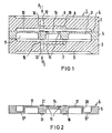
- FIG. 1 An exemplary embodiment of a measuring cell according to the invention is shown schematically in FIG. 1, Figure 2 shows another embodiment of the movable wall with measuring membrane.
- FIG. 1 The housing of the differential pressure measuring cell 1 consists essentially of two cylindrical housing bodies 2 and 3, between which a movable wall 4 is attached with its thickened clamping edge 5.
- the outer end faces of the housing bodies 2 and 3 are provided with shallow depressions which are closed off by separating membranes 6 and 7 and thus form the antechambers 8 and 9.
- the measuring pressures P1 and P2, whose differential pressure is to be measured, act in opposite directions on the separating membranes 6 and 7.
- the inner end faces of the housing bodies 2 and 3 are also provided with flat recesses which form the measuring chambers 10 and 11 and are separated from one another by the movable wall 4.
- Pressure lines 12 and 13 lead from the antechambers 8 and 9 into the measuring chambers 10 and 11.
- All cavities within the measuring cell 1 are filled with a non-compressible liquid for hydraulic pressure transmission from the separating membranes 6 and 7 to the measuring membrane 14, which forms the central part of the movable wall 4.
- the movable wall 4 is made in one piece from a semiconductor wafer, and the pressure-proportional deflection of the measuring diaphragm 14 is tapped via integrated semiconductor strain gauges 15.
- the measuring membrane 14 is surrounded by a circular thickening 16 with a trapezoidal or rectangular cross section, the parallel sides preferably lying in the end faces of the semiconductor wafer.
- the thickening 16 is followed by an annular membrane-like section 17 with a softer spring characteristic than that of the measuring membrane.
- the pressure supply lines 12 and 13 in the housing bodies 2 and 3 open into annular grooves 18, 19 in the bottom surfaces of the measuring chambers 10 and 11 parallel to the membrane plane.
- the average diameter of the grooves 18, 19 corresponds to that of the thickening 16 surrounding the measuring membrane 14, its width is smaller than the distance between the upper edges of the thickening 16.
- FIG. 2 shows another exemplary embodiment of the movable wall 4, which is produced in one piece from a semiconductor wafer by etching.
- the annular membrane-like section between the clamping edge 5 and the thickening 16 surrounding the measuring membrane 14 here consists of two concentric sections 17 and 17 ', the section adjoining the frame edge 5 lying approximately in the plane of one end face of the semiconductor wafer, the other part 17 lying in the plane of the other end face of the semiconductor wafer. Both sections 17 and 17 'are connected to one another via a hollow cylindrical intermediate piece 20.
- Thin layers 21 can be applied to the parts of the end faces of the thickening 16 opposite the annular grooves 18 and 19 to improve the sealing effect in the event of an overload between the movable wall 4 and the grooves 18 or 19.
Landscapes
- Physics & Mathematics (AREA)
- General Physics & Mathematics (AREA)
- Chemical & Material Sciences (AREA)
- Analytical Chemistry (AREA)
- Measuring Fluid Pressure (AREA)
Abstract
Description
Die Erfindung bezieht sich auf eine Differenzdruck-Meßzelle mit zwei flüssigkeitsgefüllten, mit Druckzuleitungen versehenen Meßkammern, die durch eine gemeinsame, eine zentrisch angeordnete Meßmembran enthaltende bewegliche Wand getrennt sind, wobei die bewegliche Wand aus einer Halbleiterscheibe besteht, deren als Meßmembran ausgebildeter zentrischer Teil von einer kreisförmigen Verdickung mit trapezförmigem Querschnitt umgeben ist.The invention relates to a differential pressure measuring cell with two liquid-filled measuring chambers provided with pressure supply lines, which are separated by a common movable wall containing a centrally arranged measuring membrane, the movable wall consisting of a semiconductor wafer, the central part of which is designed as a measuring membrane circular thickening with a trapezoidal cross section is surrounded.
Es sind derartige Meßzellen bekannt, bei denen im Überlastfall die Meßkammern nach außen abschließende Trennmembranen sich gegen entsprechend ausgebildete Membranbetten anlegen, wodurch die Meßkammer abgeschlossen und ein Ansteigen des Drucks in der Kammer über einen vorgegebenen Grenzwert hinaus verhindert wird. Diese Art der Überlastsicherung erfordert jedoch einen erheblichen fertigungstechnischen Aufwand.Such measuring cells are known in which, in the event of an overload, the separating membranes closing the measuring chambers lie against correspondingly designed membrane beds, thereby closing the measuring chamber and preventing an increase in the pressure in the chamber beyond a predetermined limit value. However, this type of overload protection requires a considerable manufacturing outlay.
Es besteht deshalb die Aufgabe, für Differenzdruck-Meßzellen der eingangs genannten Art eine andere Form der Überlastsicherung zu finden.There is therefore the task of finding a different form of overload protection for differential pressure measuring cells of the type mentioned at the outset.
Zur Lösung der Aufgabe wird von einem anderen, an sich bekannten Prinzip der Überlastsicherung, nämlich der Verwendung von bei Überlast ansprechenden, die Druckzuleitung verschließenden Ventilkörpern ausgegangen.To solve the problem, another known principle of overload protection, namely the use of valve bodies that respond to overload and close the pressure supply line, is assumed.
Die Differenzdruck-Meßzelle, mit der die Aufgabe gelöst ist, weist die im Anspruch 1 gekennzeichneten Merkmale auf. Als Ventilkörper wirkt hier die in der beweglichen Wand angebrachte kreisförmige Verdickung, die die zentrische Meßmembran umgibt.The differential pressure measuring cell with which the object is achieved has the features characterized in claim 1. The circular thickening in the movable wall, which surrounds the central measuring membrane, acts as the valve body.
Das Anbringen der Ringnuten als Druckzuleitungsanschluß in den BÖden der Meßkammern (z. B. durch Ätzprozesse) ist herstellungstechnisch weit weniger aufwendig als die Fertigung der Membranbetten für Trennmembranen als Überlastsicherung. Bei der Verwendung von nicht kreisrunden Membranen sind die die Meßmembran umgebende Verdickung und die Ringnuten in den Bodenflächen der Meßkammern entsprechend geformt.The production of the ring grooves as a pressure supply connection in the floors of the measuring chambers (e.g. by etching processes) is far less complex in terms of production technology than the manufacture of the membrane beds for separation membranes as overload protection. When using non-circular membranes, the thickening surrounding the measuring membrane and the annular grooves in the bottom surfaces of the measuring chambers are shaped accordingly.
Ein Ausführungsbeispiel einer erfindungsgemäßen Meßzelle ist schematisch in der Figur 1 dargestellt,
Figur 2 zeigt eine andere Ausführungsform der beweglichen Wand mit Meßmembran.An exemplary embodiment of a measuring cell according to the invention is shown schematically in FIG. 1,
Figure 2 shows another embodiment of the movable wall with measuring membrane.
Figur 1: Das Gehäuse der Differenzdruck-Meßzelle 1 besteht im wesentlichen aus zwei zylindrischen Gehäusekörpern 2 und 3, zwischen denen eine bewegliche Wand 4 mit ihrem verdickten Einspannrand 5 befestigt ist.Figure 1: The housing of the differential pressure measuring cell 1 consists essentially of two
Die außenliegenden Stirnseiten der Gehäusekörper 2 und 3 sind mit flachen Vertiefungen versehen, welche durch Trennmembranen 6 und 7 abgeschlossen sind und so die Vorkammern 8 und 9 bilden. Auf die Trennmembranen 6 und 7 wirken gegensinnig die Meßdrücke Pl und P2, deren Differenzdruck gemessen werden soll.The outer end faces of the
Die innenliegenden Stirnseiten der Gehäusekörper 2 und 3 sind ebenfalls mit flachen Ausnehmungen versehen, welche die Meßkammern 10 und 11 bilden und von der beweglichen Wand 4 voneinander getrennt sind.The inner end faces of the
Von den Vorkammern 8 und 9 führen Druckleitungen 12 und 13 in die Meßkammern 10 und 11.
Alle Hohlräume innerhalb der Meßzelle 1 sind mit einer nicht-kompressiblen Flüssigkeit gefüllt zur hydraulischen Druckübertragung von den Trennmembranen 6 und 7 auf die Meßmembran 14, die den zentrischen Teil der beweglichen Wand 4 bildet.All cavities within the measuring cell 1 are filled with a non-compressible liquid for hydraulic pressure transmission from the
In einer bevorzugten Ausführungsform ist die bewegliche Wand 4 einstückig aus einer Halbleiterscheibe hergestellt, der Abgriff der druckproportionalen Auslenkung der Meßmembran 14 erfolgt über integrierte Halbleiter-Dehnungsmeßstreifen 15.In a preferred embodiment, the movable wall 4 is made in one piece from a semiconductor wafer, and the pressure-proportional deflection of the
Die Meßmembran 14 ist von einer kreisförmigen Verdickung 16 mit trapezförmigem bzw. rechteckigem Querschnitt umgeben, wobei die parallelen Seiten vorzugsweise in den Stirnflächen der Halbleiterscheibe liegen. Auf die Verdickung 16 folgt ein ringmembranartiger Abschnitt 17 mit weicherer Federcharakteristik als die der Meßmembran.The
Die Druckzuleitungen 12 und 13 in den Gehäusekörpern 2 und 3 münden in ringförmige Nuten 18, 19 in den zur Membranebene parallelen Bodenflächen der Meßkammern 10 und 11.The pressure supply lines 12 and 13 in the
Der mittlere Durchmesser der Nuten 18, 19 entspricht dem der die Meßmembran 14 umgebenden Verdickung 16, ihre Breite ist kleiner als der Abstand zwischen den Oberkanten der Verdickung 16.The average diameter of the
Zur Funktion: Beim Auftreten eines Überdrucks in der Differenzdruck-Meßzelle, beispielsweise durch Ausfall des Drucks P2, wird die bewegliche Wand 4 so weit ausgelenkt, daß die kreisringförmige, plane Stirnfläche der Verdickung 16 auf der Nut 19 aufliegt, diese verschließt und somit einen weiteren, zur Beschädigung der Meßmembran 14 führenden Druckabfall in der Meßkammer 11 verhindert.Function: When an overpressure occurs in the differential pressure measuring cell, for example due to a loss of pressure P2, the movable wall 4 is deflected to such an extent that the annular, flat end face of the
Fällt der Druck Pl aus, wird entsprechend die Nut 18 verschlossen.If the pressure Pl fails, the
In Figur 2 ist ein anderes Ausführungsbeispiel der aus einer Halbleiterscheibe durch Ätzen einstückig hergestellten beweglichen Wand 4 gezeigt.FIG. 2 shows another exemplary embodiment of the movable wall 4, which is produced in one piece from a semiconductor wafer by etching.
Der ringmembranartige Abschnitt zwischen dem Einspannrand 5 und der die Meßmembran 14 umgebenden Verdickung 16 besteht hier aus zwei konzentrischen Abschnitten 17 und 17', wobei der an den Fassungsrand 5 anschließende Abschnitt etwa in der Ebene der einen Stirnfläche der Halbleiterscheibe, der andere Teil 17 in der Ebene der anderen Stirnfläche der Halbleiterscheibe liegt. Beide Abschnitte 17 und 17' sind über ein hohlzylindrisches Zwischenstück 20 miteinander verbunden.The annular membrane-like section between the
Mit dieser Ausführung kann eine besonders weiche Federcharakteristik der Ringmembranen und entsprechend ein leichtes Ansprechen auf Überdruck erzielt werden.With this design, a particularly soft spring characteristic of the ring membranes and, accordingly, a slight response to overpressure can be achieved.
Auf den den Ringnuten 18 und 19 gegenüberliegenden Teilen der Stirnflächen der Verdickung 16 können dünne Schichten 21 aufgebracht werden zur Verbesserung der Dichtwirkung im Überlastfall zwischen beweglicher Wand 4 und den Nuten 18 oder 19.
Claims (3)
und daß die Druckzuleitungen (12, 13) in die Ringnuten (18, 19) münden.1. Differential pressure measuring cell with two liquid-filled, pressure supply measuring chambers, which are separated by a common, centrally located measuring membrane containing movable wall, the movable wall consisting of a semiconductor wafer, the central part of which is designed as a measuring membrane and has an annular thickening with a trapezoidal shape Cross-section is surrounded, characterized in that an annular groove (18, 19) is provided in the bottom surface of each measuring chamber (10, 11) parallel to the membrane plane, the mean diameter of which corresponds to that of the thickening (16) surrounding the measuring membrane (14) and its width is smaller than the distance between the upper edges of the thickening (16),
and that the pressure supply lines (12, 13) open into the annular grooves (18, 19).
und daß Meßmembran (14) und Ringmembran (17) etwa in der Ebene der einen Stirnfläche der Halbleiterscheibe liegen und der Fassungsrand (5) und die kreisförmige Verdickung (16) sich in Axialrichtung bis zur Ebene der anderen Stirnfläche erstrecken.2. Differential pressure measuring cell according to claim 1, characterized in that the part of the movable wall surrounding the thickening (16) is designed as an annular membrane (17) which merges into a clamping edge (5).
and that the measuring diaphragm (14) and the ring diaphragm (17) lie approximately in the plane of one end face of the semiconductor wafer and the frame edge (5) and the circular thickening (16) extend in the axial direction to the level of the other end face.
Applications Claiming Priority (2)
| Application Number | Priority Date | Filing Date | Title |
|---|---|---|---|
| DE3425198 | 1984-07-09 | ||
| DE3425198 | 1984-07-09 |
Publications (2)
| Publication Number | Publication Date |
|---|---|
| EP0167941A2 true EP0167941A2 (en) | 1986-01-15 |
| EP0167941A3 EP0167941A3 (en) | 1988-10-05 |
Family
ID=6240167
Family Applications (1)
| Application Number | Title | Priority Date | Filing Date |
|---|---|---|---|
| EP85108024A Withdrawn EP0167941A3 (en) | 1984-07-09 | 1985-06-28 | Differential pressure gauge head |
Country Status (1)
| Country | Link |
|---|---|
| EP (1) | EP0167941A3 (en) |
Cited By (9)
| Publication number | Priority date | Publication date | Assignee | Title |
|---|---|---|---|---|
| DE29712579U1 (en) * | 1997-07-16 | 1998-08-20 | Siemens Ag | Differential pressure transmitter |
| WO2001084101A2 (en) * | 2000-05-04 | 2001-11-08 | Rosemount Inc. | Pressure transmitter with improved isolator system |
| US6457367B1 (en) | 1999-09-28 | 2002-10-01 | Rosemount Inc. | Scalable process transmitter |
| US6571132B1 (en) | 1999-09-28 | 2003-05-27 | Rosemount Inc. | Component type adaptation in a transducer assembly |
| US6765968B1 (en) | 1999-09-28 | 2004-07-20 | Rosemount Inc. | Process transmitter with local databus |
| US7773715B2 (en) | 2002-09-06 | 2010-08-10 | Rosemount Inc. | Two wire transmitter with isolated can output |
| US8334788B2 (en) | 2010-03-04 | 2012-12-18 | Rosemount Inc. | Process variable transmitter with display |
| CN104316255A (en) * | 2014-10-14 | 2015-01-28 | 秦川机床集团宝鸡仪表有限公司 | Loading limit protection device of pressure sensor |
| US20160084722A1 (en) * | 2014-09-24 | 2016-03-24 | Freescale Semiconductor Inc. | Differential Pressure Sensor Assembly |
Families Citing this family (6)
| Publication number | Priority date | Publication date | Assignee | Title |
|---|---|---|---|---|
| US6510740B1 (en) | 1999-09-28 | 2003-01-28 | Rosemount Inc. | Thermal management in a pressure transmitter |
| US6487912B1 (en) | 1999-09-28 | 2002-12-03 | Rosemount Inc. | Preinstallation of a pressure sensor module |
| AU7835100A (en) | 1999-09-28 | 2001-04-30 | Rosemount Inc. | Environmentally sealed instrument loop adapter |
| US6480131B1 (en) | 2000-08-10 | 2002-11-12 | Rosemount Inc. | Multiple die industrial process control transmitter |
| US6516672B2 (en) | 2001-05-21 | 2003-02-11 | Rosemount Inc. | Sigma-delta analog to digital converter for capacitive pressure sensor and process transmitter |
| US6684711B2 (en) | 2001-08-23 | 2004-02-03 | Rosemount Inc. | Three-phase excitation circuit for compensated capacitor industrial process control transmitters |
Citations (6)
| Publication number | Priority date | Publication date | Assignee | Title |
|---|---|---|---|---|
| CH186010A (en) * | 1935-01-08 | 1936-08-31 | Manometer A G | Diaphragm pressure meter. |
| DE7703675U1 (en) * | 1977-02-08 | 1977-06-30 | Siemens Ag, 1000 Berlin Und 8000 Muenchen | DEVICE FOR PROTECTING A SEMICONDUCTOR MEASUREMENT DIAPHRAGM AGAINST OVERLOAD |
| DE2659376A1 (en) * | 1976-12-29 | 1978-07-06 | Siemens Ag | DIFFERENTIAL PRESSURE MEASURING CELL |
| GB2065893A (en) * | 1979-12-19 | 1981-07-01 | Hitachi Ltd | Differential pressure transducer |
| EP0059488A1 (en) * | 1978-07-21 | 1982-09-08 | Hitachi, Ltd. | Capacitive pressure sensor |
| EP0115074A2 (en) * | 1982-12-29 | 1984-08-08 | Fuji Electric Co. Ltd. | Differential pressure measuring device |
-
1985
- 1985-06-28 EP EP85108024A patent/EP0167941A3/en not_active Withdrawn
Patent Citations (6)
| Publication number | Priority date | Publication date | Assignee | Title |
|---|---|---|---|---|
| CH186010A (en) * | 1935-01-08 | 1936-08-31 | Manometer A G | Diaphragm pressure meter. |
| DE2659376A1 (en) * | 1976-12-29 | 1978-07-06 | Siemens Ag | DIFFERENTIAL PRESSURE MEASURING CELL |
| DE7703675U1 (en) * | 1977-02-08 | 1977-06-30 | Siemens Ag, 1000 Berlin Und 8000 Muenchen | DEVICE FOR PROTECTING A SEMICONDUCTOR MEASUREMENT DIAPHRAGM AGAINST OVERLOAD |
| EP0059488A1 (en) * | 1978-07-21 | 1982-09-08 | Hitachi, Ltd. | Capacitive pressure sensor |
| GB2065893A (en) * | 1979-12-19 | 1981-07-01 | Hitachi Ltd | Differential pressure transducer |
| EP0115074A2 (en) * | 1982-12-29 | 1984-08-08 | Fuji Electric Co. Ltd. | Differential pressure measuring device |
Cited By (12)
| Publication number | Priority date | Publication date | Assignee | Title |
|---|---|---|---|---|
| DE29712579U1 (en) * | 1997-07-16 | 1998-08-20 | Siemens Ag | Differential pressure transmitter |
| US6457367B1 (en) | 1999-09-28 | 2002-10-01 | Rosemount Inc. | Scalable process transmitter |
| US6571132B1 (en) | 1999-09-28 | 2003-05-27 | Rosemount Inc. | Component type adaptation in a transducer assembly |
| US6765968B1 (en) | 1999-09-28 | 2004-07-20 | Rosemount Inc. | Process transmitter with local databus |
| WO2001084101A2 (en) * | 2000-05-04 | 2001-11-08 | Rosemount Inc. | Pressure transmitter with improved isolator system |
| WO2001084101A3 (en) * | 2000-05-04 | 2002-05-30 | Rosemount Inc | Pressure transmitter with improved isolator system |
| US7773715B2 (en) | 2002-09-06 | 2010-08-10 | Rosemount Inc. | Two wire transmitter with isolated can output |
| US8208581B2 (en) | 2002-09-06 | 2012-06-26 | Rosemount Inc. | Two wire transmitter with isolated can output |
| US8334788B2 (en) | 2010-03-04 | 2012-12-18 | Rosemount Inc. | Process variable transmitter with display |
| US20160084722A1 (en) * | 2014-09-24 | 2016-03-24 | Freescale Semiconductor Inc. | Differential Pressure Sensor Assembly |
| US9638597B2 (en) * | 2014-09-24 | 2017-05-02 | Nxp Usa, Inc. | Differential pressure sensor assembly |
| CN104316255A (en) * | 2014-10-14 | 2015-01-28 | 秦川机床集团宝鸡仪表有限公司 | Loading limit protection device of pressure sensor |
Also Published As
| Publication number | Publication date |
|---|---|
| EP0167941A3 (en) | 1988-10-05 |
Similar Documents
| Publication | Publication Date | Title |
|---|---|---|
| EP0167941A2 (en) | Differential pressure gauge head | |
| EP1299701B1 (en) | Differential pressure sensor | |
| EP1305585B1 (en) | Capacitive pressure sensor | |
| EP1537395B1 (en) | Capacitive pressure sensor | |
| EP0086737A1 (en) | Device for measuring pressure or pressure difference using a measuring transducer protected against overpressure | |
| EP2223070A1 (en) | Differential pressure measuring cell | |
| DE2935476B2 (en) | Liquid-filled differential pressure transducer | |
| DE3702412C2 (en) | ||
| DE102017103120A1 (en) | Pressure sensor chip and pressure sensor | |
| DE2911349C2 (en) | Vacuum protection device and method for a differential pressure transducer | |
| DE1473689A1 (en) | Electrical pressure transducer | |
| DE4133008A1 (en) | CAPACITIVE PRESSURE SENSOR AND PRODUCTION METHOD THEREFOR | |
| EP0115074B1 (en) | Differential pressure measuring device | |
| WO2012055605A2 (en) | Pressure transducer | |
| DE4207949C1 (en) | Capacitative differential pressure sensor of glass-silicon@ type - has second pressure supply channel communicating with first but offset in covering plate | |
| DE102017109971A1 (en) | pressure sensor | |
| DE3148403A1 (en) | Differential pressure meter | |
| DE2657933C3 (en) | Differential pressure transmitter with overload protection | |
| EP0849577B1 (en) | Membrane for determining the pressure | |
| DE2659376C2 (en) | Differential pressure measuring cell | |
| EP0106900A1 (en) | Force-measuring transducer | |
| DE102016107235B3 (en) | Differential pressure measuring cell | |
| AT408920B (en) | Differential pressure measuring cell | |
| DD279065A1 (en) | DIFFERENTIAL PRESSURE TRANSMITTER WITH OVERLOAD PROTECTION DEVICE | |
| DE2910269A1 (en) | Temp. gradient compensation of differential pressure transducer - forms parts of one chamber in different temperature regions |
Legal Events
| Date | Code | Title | Description |
|---|---|---|---|
| PUAI | Public reference made under article 153(3) epc to a published international application that has entered the european phase |
Free format text: ORIGINAL CODE: 0009012 |
|
| AK | Designated contracting states |
Designated state(s): AT BE CH DE FR GB IT LI NL |
|
| PUAL | Search report despatched |
Free format text: ORIGINAL CODE: 0009013 |
|
| AK | Designated contracting states |
Kind code of ref document: A3 Designated state(s): AT BE CH DE FR GB IT LI NL |
|
| STAA | Information on the status of an ep patent application or granted ep patent |
Free format text: STATUS: THE APPLICATION IS DEEMED TO BE WITHDRAWN |
|
| 18D | Application deemed to be withdrawn |
Effective date: 19890406 |
|
| RIN1 | Information on inventor provided before grant (corrected) |
Inventor name: SCHWAIER, ARNOLD, DIPL.-ING. |