EP0165320B1 - Disk-shaped recording medium and apparatus for reproducing the same - Google Patents
Disk-shaped recording medium and apparatus for reproducing the same Download PDFInfo
- Publication number
- EP0165320B1 EP0165320B1 EP85900170A EP85900170A EP0165320B1 EP 0165320 B1 EP0165320 B1 EP 0165320B1 EP 85900170 A EP85900170 A EP 85900170A EP 85900170 A EP85900170 A EP 85900170A EP 0165320 B1 EP0165320 B1 EP 0165320B1
- Authority
- EP
- European Patent Office
- Prior art keywords
- data
- disc
- lead
- track
- reproducing
- Prior art date
- Legal status (The legal status is an assumption and is not a legal conclusion. Google has not performed a legal analysis and makes no representation as to the accuracy of the status listed.)
- Expired - Lifetime
Links
Images


Classifications
-
- G—PHYSICS
- G11—INFORMATION STORAGE
- G11B—INFORMATION STORAGE BASED ON RELATIVE MOVEMENT BETWEEN RECORD CARRIER AND TRANSDUCER
- G11B20/00—Signal processing not specific to the method of recording or reproducing; Circuits therefor
- G11B20/10—Digital recording or reproducing
- G11B20/18—Error detection or correction; Testing, e.g. of drop-outs
- G11B20/1806—Pulse code modulation systems for audio signals
- G11B20/1809—Pulse code modulation systems for audio signals by interleaving
-
- G—PHYSICS
- G11—INFORMATION STORAGE
- G11B—INFORMATION STORAGE BASED ON RELATIVE MOVEMENT BETWEEN RECORD CARRIER AND TRANSDUCER
- G11B19/00—Driving, starting, stopping record carriers not specifically of filamentary or web form, or of supports therefor; Control thereof; Control of operating function ; Driving both disc and head
- G11B19/02—Control of operating function, e.g. switching from recording to reproducing
-
- G—PHYSICS
- G11—INFORMATION STORAGE
- G11B—INFORMATION STORAGE BASED ON RELATIVE MOVEMENT BETWEEN RECORD CARRIER AND TRANSDUCER
- G11B20/00—Signal processing not specific to the method of recording or reproducing; Circuits therefor
- G11B20/10—Digital recording or reproducing
-
- G—PHYSICS
- G11—INFORMATION STORAGE
- G11B—INFORMATION STORAGE BASED ON RELATIVE MOVEMENT BETWEEN RECORD CARRIER AND TRANSDUCER
- G11B20/00—Signal processing not specific to the method of recording or reproducing; Circuits therefor
- G11B20/10—Digital recording or reproducing
- G11B20/10527—Audio or video recording; Data buffering arrangements
-
- G—PHYSICS
- G11—INFORMATION STORAGE
- G11B—INFORMATION STORAGE BASED ON RELATIVE MOVEMENT BETWEEN RECORD CARRIER AND TRANSDUCER
- G11B20/00—Signal processing not specific to the method of recording or reproducing; Circuits therefor
- G11B20/10—Digital recording or reproducing
- G11B20/12—Formatting, e.g. arrangement of data block or words on the record carriers
- G11B20/1217—Formatting, e.g. arrangement of data block or words on the record carriers on discs
- G11B20/1254—Formatting, e.g. arrangement of data block or words on the record carriers on discs for mixed data, i.e. continuous and discontinuous data
-
- G—PHYSICS
- G11—INFORMATION STORAGE
- G11B—INFORMATION STORAGE BASED ON RELATIVE MOVEMENT BETWEEN RECORD CARRIER AND TRANSDUCER
- G11B27/00—Editing; Indexing; Addressing; Timing or synchronising; Monitoring; Measuring tape travel
- G11B27/10—Indexing; Addressing; Timing or synchronising; Measuring tape travel
- G11B27/19—Indexing; Addressing; Timing or synchronising; Measuring tape travel by using information detectable on the record carrier
- G11B27/28—Indexing; Addressing; Timing or synchronising; Measuring tape travel by using information detectable on the record carrier by using information signals recorded by the same method as the main recording
- G11B27/30—Indexing; Addressing; Timing or synchronising; Measuring tape travel by using information detectable on the record carrier by using information signals recorded by the same method as the main recording on the same track as the main recording
- G11B27/3027—Indexing; Addressing; Timing or synchronising; Measuring tape travel by using information detectable on the record carrier by using information signals recorded by the same method as the main recording on the same track as the main recording used signal is digitally coded
- G11B27/3063—Subcodes
-
- G—PHYSICS
- G11—INFORMATION STORAGE
- G11B—INFORMATION STORAGE BASED ON RELATIVE MOVEMENT BETWEEN RECORD CARRIER AND TRANSDUCER
- G11B27/00—Editing; Indexing; Addressing; Timing or synchronising; Monitoring; Measuring tape travel
- G11B27/10—Indexing; Addressing; Timing or synchronising; Measuring tape travel
- G11B27/19—Indexing; Addressing; Timing or synchronising; Measuring tape travel by using information detectable on the record carrier
- G11B27/28—Indexing; Addressing; Timing or synchronising; Measuring tape travel by using information detectable on the record carrier by using information signals recorded by the same method as the main recording
- G11B27/32—Indexing; Addressing; Timing or synchronising; Measuring tape travel by using information detectable on the record carrier by using information signals recorded by the same method as the main recording on separate auxiliary tracks of the same or an auxiliary record carrier
- G11B27/327—Table of contents
- G11B27/329—Table of contents on a disc [VTOC]
-
- G—PHYSICS
- G11—INFORMATION STORAGE
- G11B—INFORMATION STORAGE BASED ON RELATIVE MOVEMENT BETWEEN RECORD CARRIER AND TRANSDUCER
- G11B7/00—Recording or reproducing by optical means, e.g. recording using a thermal beam of optical radiation by modifying optical properties or the physical structure, reproducing using an optical beam at lower power by sensing optical properties; Record carriers therefor
- G11B7/004—Recording, reproducing or erasing methods; Read, write or erase circuits therefor
- G11B7/005—Reproducing
-
- G—PHYSICS
- G11—INFORMATION STORAGE
- G11B—INFORMATION STORAGE BASED ON RELATIVE MOVEMENT BETWEEN RECORD CARRIER AND TRANSDUCER
- G11B7/00—Recording or reproducing by optical means, e.g. recording using a thermal beam of optical radiation by modifying optical properties or the physical structure, reproducing using an optical beam at lower power by sensing optical properties; Record carriers therefor
- G11B7/007—Arrangement of the information on the record carrier, e.g. form of tracks, actual track shape, e.g. wobbled, or cross-section, e.g. v-shaped; Sequential information structures, e.g. sectoring or header formats within a track
- G11B7/013—Arrangement of the information on the record carrier, e.g. form of tracks, actual track shape, e.g. wobbled, or cross-section, e.g. v-shaped; Sequential information structures, e.g. sectoring or header formats within a track for discrete information, i.e. where each information unit is stored in a distinct discrete location, e.g. digital information formats within a data block or sector
-
- H—ELECTRICITY
- H04—ELECTRIC COMMUNICATION TECHNIQUE
- H04N—PICTORIAL COMMUNICATION, e.g. TELEVISION
- H04N5/00—Details of television systems
- H04N5/76—Television signal recording
- H04N5/91—Television signal processing therefor
- H04N5/92—Transformation of the television signal for recording, e.g. modulation, frequency changing; Inverse transformation for playback
- H04N5/9201—Transformation of the television signal for recording, e.g. modulation, frequency changing; Inverse transformation for playback involving the multiplexing of an additional signal and the video signal
- H04N5/9202—Transformation of the television signal for recording, e.g. modulation, frequency changing; Inverse transformation for playback involving the multiplexing of an additional signal and the video signal the additional signal being a sound signal
- H04N5/9203—Transformation of the television signal for recording, e.g. modulation, frequency changing; Inverse transformation for playback involving the multiplexing of an additional signal and the video signal the additional signal being a sound signal using time division multiplex
-
- H—ELECTRICITY
- H04—ELECTRIC COMMUNICATION TECHNIQUE
- H04N—PICTORIAL COMMUNICATION, e.g. TELEVISION
- H04N5/00—Details of television systems
- H04N5/76—Television signal recording
- H04N5/91—Television signal processing therefor
- H04N5/92—Transformation of the television signal for recording, e.g. modulation, frequency changing; Inverse transformation for playback
- H04N5/9201—Transformation of the television signal for recording, e.g. modulation, frequency changing; Inverse transformation for playback involving the multiplexing of an additional signal and the video signal
- H04N5/9206—Transformation of the television signal for recording, e.g. modulation, frequency changing; Inverse transformation for playback involving the multiplexing of an additional signal and the video signal the additional signal being a character code signal
- H04N5/9208—Transformation of the television signal for recording, e.g. modulation, frequency changing; Inverse transformation for playback involving the multiplexing of an additional signal and the video signal the additional signal being a character code signal involving the use of subcodes
-
- H—ELECTRICITY
- H04—ELECTRIC COMMUNICATION TECHNIQUE
- H04N—PICTORIAL COMMUNICATION, e.g. TELEVISION
- H04N5/00—Details of television systems
- H04N5/76—Television signal recording
- H04N5/91—Television signal processing therefor
- H04N5/92—Transformation of the television signal for recording, e.g. modulation, frequency changing; Inverse transformation for playback
- H04N5/926—Transformation of the television signal for recording, e.g. modulation, frequency changing; Inverse transformation for playback by pulse code modulation
- H04N5/9265—Transformation of the television signal for recording, e.g. modulation, frequency changing; Inverse transformation for playback by pulse code modulation with processing of the sound signal
- H04N5/9267—Transformation of the television signal for recording, e.g. modulation, frequency changing; Inverse transformation for playback by pulse code modulation with processing of the sound signal using time division multiplex of the PCM audio and PCM video signals
-
- H—ELECTRICITY
- H04—ELECTRIC COMMUNICATION TECHNIQUE
- H04N—PICTORIAL COMMUNICATION, e.g. TELEVISION
- H04N5/00—Details of television systems
- H04N5/76—Television signal recording
- H04N5/91—Television signal processing therefor
- H04N5/93—Regeneration of the television signal or of selected parts thereof
- H04N5/9305—Regeneration of the television signal or of selected parts thereof involving the mixing of the reproduced video signal with a non-recorded signal, e.g. a text signal
-
- G—PHYSICS
- G11—INFORMATION STORAGE
- G11B—INFORMATION STORAGE BASED ON RELATIVE MOVEMENT BETWEEN RECORD CARRIER AND TRANSDUCER
- G11B20/00—Signal processing not specific to the method of recording or reproducing; Circuits therefor
- G11B20/10—Digital recording or reproducing
- G11B20/12—Formatting, e.g. arrangement of data block or words on the record carriers
- G11B20/1217—Formatting, e.g. arrangement of data block or words on the record carriers on discs
-
- G—PHYSICS
- G11—INFORMATION STORAGE
- G11B—INFORMATION STORAGE BASED ON RELATIVE MOVEMENT BETWEEN RECORD CARRIER AND TRANSDUCER
- G11B20/00—Signal processing not specific to the method of recording or reproducing; Circuits therefor
- G11B20/10—Digital recording or reproducing
- G11B20/10527—Audio or video recording; Data buffering arrangements
- G11B2020/10537—Audio or video recording
- G11B2020/10546—Audio or video recording specifically adapted for audio data
-
- G—PHYSICS
- G11—INFORMATION STORAGE
- G11B—INFORMATION STORAGE BASED ON RELATIVE MOVEMENT BETWEEN RECORD CARRIER AND TRANSDUCER
- G11B20/00—Signal processing not specific to the method of recording or reproducing; Circuits therefor
- G11B20/10—Digital recording or reproducing
- G11B20/10527—Audio or video recording; Data buffering arrangements
- G11B2020/10537—Audio or video recording
- G11B2020/10592—Audio or video recording specifically adapted for recording or reproducing multichannel signals
-
- G—PHYSICS
- G11—INFORMATION STORAGE
- G11B—INFORMATION STORAGE BASED ON RELATIVE MOVEMENT BETWEEN RECORD CARRIER AND TRANSDUCER
- G11B20/00—Signal processing not specific to the method of recording or reproducing; Circuits therefor
- G11B20/10—Digital recording or reproducing
- G11B2020/1087—Digital recording or reproducing wherein a selection is made among at least two alternative ways of processing
- G11B2020/10888—Digital recording or reproducing wherein a selection is made among at least two alternative ways of processing the kind of data being the selection criterion
-
- G—PHYSICS
- G11—INFORMATION STORAGE
- G11B—INFORMATION STORAGE BASED ON RELATIVE MOVEMENT BETWEEN RECORD CARRIER AND TRANSDUCER
- G11B2220/00—Record carriers by type
- G11B2220/20—Disc-shaped record carriers
- G11B2220/25—Disc-shaped record carriers characterised in that the disc is based on a specific recording technology
- G11B2220/2537—Optical discs
- G11B2220/2545—CDs
-
- G—PHYSICS
- G11—INFORMATION STORAGE
- G11B—INFORMATION STORAGE BASED ON RELATIVE MOVEMENT BETWEEN RECORD CARRIER AND TRANSDUCER
- G11B2220/00—Record carriers by type
- G11B2220/40—Combinations of multiple record carriers
- G11B2220/41—Flat as opposed to hierarchical combination, e.g. library of tapes or discs, CD changer, or groups of record carriers that together store one title
Definitions
- This invention relates to a disc recording medium and an apparatus for playback thereof.
- the system employing an optically encoded digital audio disc (referred to hereafter as a compact disc) system, which is applied with an error correcting code of high correctability, can reproduce high-quality stereo music. If character data, still picture data and video game program are recoded together with the stereo music data on the same compact disc in the same signal format employing the same error correcting code, it becomes possible to reproduce still pictures such as paintings corresponding to the reproduced music or to display the composer's name and the title of the music piece while the user enjoys the reproduced stereo music, and also possible to reproduce suitable music for running video programs so as to expand the field or application of the present compact disc system.
- One prior-art compact disc has a data storage capacity of about 500 M bytes and thus can afford to store both stereo musical data and digital data.
- disc playback systems which are able to play both prior art compact discs and discs storing the two kinds of data as described above, or further able to reproduce discs storing solely non-audio digital data.
- the discs on which only stereo music is recorded with the structure of disc according to the invention, not only persons who own the conventional disc playback systems are able to enjoy high-quality stereo music as before, but also persons who own the new type disc playback system to which are added display devices and so on are able to enjoy both reproduction of stereo music and reproduction of still pictures according to this invention.
- the conventional disc playback system aims at reproducing stereo music
- the disc storing digital data such as still picture data other than musical data
- high level noise is generated so as to cause problems such as to damage loudspeakers and so on.
- the desired disc must prohibit prior art disc playback systems from audibly reproducing digital data other than stereo music.
- One method is to store the digital data in a pause section between of section of musical data and another section of musical data.
- this pause section is not necessarily mute but is sometimes treated as a fade-in and fade-out section. Since prior art disc playback systems cannot hold the pause section mute, the pause section cannot usefully store digital data.
- EP-A-0137855 proposes a digital disc having audio and visual data stored thereon, the two types of data being interleaved between one another. It is possible for the pick-up head of the disc player to drift in use, and with such an arrangement, the visual data may be reproduced by the audio reproducing circuitry thus producing noise and possible damage to the disc player.
- JP-A-58-64603 discloses a video disc comprising identification data tracks at an outermost circumference followed by warning data tracks, control tracks and video tracks.
- the warning data are only reproduced in a general purpose reproduction system. It is well known to provide CDs with a lead-in track and a lead-out track.
- a disc storing data of a first kind in a first annular area bounded by a first lead-in track and a first lead-out track, and to be reproduced in a direction from the first lead-in track towards the first lead-out track, characterized in that a second annular area succeeds, in said direction of reproducing, the first annular area and stores data of a second kind and in that recognition data for distinguishing the disk containing both said first and second kinds of data - from a conventional type of disc containing only the first kind of data, is recorded in a touch preceding, in the direction of reproducing the first annular area.
- first digital data such as stereo musical and second digital data such as still picture data which can be used in prior art disc playback systems which are able to play only the first type of digital data. This also minimizes the waiting time to start reproducing the first type of digital data.
- An apparatus can use both prior art digital discs storing, for example only stereo music data, and discs storing two kinds of data, for example stereo music data and still picture data. In particular it is able to prevent noise from being generated due to a prior art apparatus reproducing digital data other than audio data.
- a disc recording medium stores a first type of digital data and a second type of digital data after the end of the first type of digital data,and comprises a lead-in track which includes recognition data indicating whether the disc stores the second type of digital data.
- the present invention also provides a disc playback apparatus capable of playing a disc having a first recording region for storing a first type of data signal, a second recording region succeeding the first recording region and for storing a second type of data signal a lead-in region preceding the first recording region and for storing an identifying data signal for indicating the presence of the second recording region, characterised in that it comprises: a first reproduction processing circuit for reproducing the first type of data signal; a second reproduction processing circuit for reproducing the second type of data signal; and a control circuit supplied with the identifying data signal and for outputting a signal controlling operation of said pickup means and said first and second reproduction processing circuits; characterised in that the disc has a lead-out region between the first recording region and the second recording region and for storing an end a data signal for indicating the end of the first recording region; and said control circuit controls said pickup means so as to move, after reading the lead-in region and when the identifying data signal indicates the presence of the second recording region to the second recording region and then to return to the first
- Fig. 1 illustrates a data stream as stored in the compact disc.
- One frame consists of 588 bits of data to be recorded and includes a frame synchronizing pulse FS of a particular bit pattern which is followed by the first direct-current component constraint bits group RB consisting of 3 bits.
- the 0th to 32nd groups of data bits DB each consisting of 14 bits, and groups of direct-current component constraint bits RB, each consisting of 3 bits, are provided alternately.
- the 0th data bits DB constitute a subcoding signal or user's bits which serves for controlling disc playback or for indicating related information.
- the 1st to 12th and 17th to 28th groups of data bits DB are allocated to audio data in a main channel, and the rest, 13th to 16th and 29th to 32nd groups of data bits DB are allocated to parity data for error correction of the main channel.
- Each group of data bits DB has 14 bits of data which have been converted during recording from 8 bits of data by an 8-14 modulation technique (EFM).
- EFM 8-14 modulation technique
- Fig. 2 shows a reproduced block consisting of 98 parallel successive frames in which each group of data bits DB is converted back to 8 bits and each set of direct current component constraint bits RB is excluded.
- the subcoding signals P to W constitute synchronizing patterns having particular bit patterns.
- the last 16 of the 98 frames constitute an error detection CRC code.
- the P-channel is a flag indicating whether the frame is a pause or music, a high level indicating a pause, a low level indicating music and a 2 Hz pulse indicating a lead-out section, so that the detecting and counting the P-channel bits makes the selection of a designated musical piece possible.
- the Q-channel performs similar but more complicated control. Specifically, the Q-channel information can be supplied to a microprocessor built into the disc playback apparatus to allow random music selection to reproduce another music track immediately after reproducing the currently selected music track.
- the remaining channels R through W constitute regions for data indicating the songwriter, composer, text and explanation of the music recorded on the disc by means of a display or voice.
- the first 2 bits serve as part of the synchronizing signal pattern, the next 4 bits serve as control bits, the following 4 bits serve as address bits, the subsequent 72 bits serve as data bits, and the final 16 bits serve as a CRC code.
- the last 96 bits of the Q-channel are defined as a data construction as shown in Fig. 3A.
- the control bits of 1st to 4th bits and address bits of 5th to 8th bits are followed by 72 bits of data.
- the data bits include a track number code TNR of 8 bits in two 4 bit portions which vary to represent the decimal members from 0 to 9 so that the track number code TNR varies from 00 to 99.
- the track number TNR is 00 in the lead-in track.
- the 8 bits following the track number bits represent a pointer.
- the 4 bits following the pointer represent minutes (MIN) data
- the 4 bits following the minutes data represent seconds (SEC) data
- the 4 bits following the seconds data represent frames data (75 frames equivalent to one second).
- the 8 bits following the 49th bit are set as all 0 and subsequent every 4 bits represent minutes, seconds and frames data of the point.
- the lead-in track and musical program area is stored data of minutes, seconds and frames which vary with time from zero minutes, zero seconds and zero frames to the lead-in track or to the end of a musical program.
- the lead-in track stores TOC (Table Of Contents) data enumerating what is stored in the disc and consists of a pointer and minutes, seconds and frames data. That is, the values of minutes, seconds and frames of the starting point of each musical program bearing a particular track number together with the value of the pointer, constitute the data in the Q-channel of the lead-in track.
- TOC Table Of Contents
- the minutes data represents the track number of a first musical program in the disc, and both the data of seconds and frames are zero. If the pointer value is A1, the minute data represents the track number of the last musical program in the disc, and both the data of seconds and frames are zero. If the pointer value is A2, the minutes, seconds and frames data represent the starting point of a lead-out track.
- the lead-in track stores the data in the Q-channel but does not store the stereo musical data in the main channel. Likewise, the lead-out track does not store stereo musical data.
- the standards for the prior art compact disc allow the presence of a maximum of 4 bits of data including the last bit of a 16-bits data.
- Fig. 3b illustrates an arrangement of data in the Q-channel in the program area.
- the first 4 bits constitute the control bits, the next 4 bits following the control bits constitute the address bits.
- the following 8 bits represent the track number TNR.
- the track number TNR of the lead-in track is 00.
- the track numbers TNR of the musical program area can take any value from 01 to 99.
- the track number TNR of the lead-out track is AA.
- the lead-out track starts from the end point of the last musical program stored in the disc.
- the 8 bits following the track number TNR represent an index X.
- the index X serves to separate each musical program and increases incrementally from 01 to maximum 99. In a pause section, the index always contains 00. Minutes, seconds and frames data following the index X represents the time-elapsed of the musical program or pause. All of minutes (A MIN), seconds (A SEC) and frames (A FRAME) data following the all-zero 8 bits constitutes an absolute time data representing the time-elapsed from the very beginning of the musical program area to the end of the lead-out track. The data stored in the compact disc are accessible by reference to the absolute time code.
- control bits in the Q-channel are defined as shown in Fig. 3C.
- the symbol X represents a non-defined bit and may be either 0 or 1.
- Control bits (00X0) mean a non-preemphasized 2-channel audio data.
- Control bits (10XX) and (01X1) are not yet defined.
- Control bits (01X0) mean that the disc stores digital data such as still picture data.
- Control bits (XX0X) mean inhibition of reproduction of the non-audio digital data
- control bits (XX1X) mean allowance of reproduction of the non-audio digital data.
- a disc storing both stereo musical data and other digital data has control bits (01X1).
- the reference numeral 1 designates a prior art compact disc
- the reference numeral 2 designates a central hole therein.
- the compact disc 1 is applied with a reproducing laser beam from its underside, and plays back from the inner periphery towards the outer periphery thereof.
- the diameter of the central hole 2 is 15mm.
- the reference numeral 3 designates a clamping area (having a radial range of 26 mm to 33 mm) where the compact disc 1 is supported, when the compact disc 1 is inserted into the player.
- the reference numeral 4 designates the program area (having a radial range of 50 mm to 116 mm)
- the reference numeral 5 designates an information area (having a radial range of 45 mm to 118 mm).
- the starting point 6 (at a maximum radius of 46 mm) of the lead-in text is located radially inward of the program area 4 but within the information area 5.
- the final lead-out point 7 is located radially outward of the
- a disc according to an embodiment of the invention has the same thickness and diameter as a conventional compact disc 1 and stores both stereo musical data and other digital data as the main channel data.
- the arrangement of data in the P-channel and Q-channel of the subcoding signals in the disc of this invention are the same as in the conventional compact disc.
- the Fig. 5 illustrates the recording format of the digital data.
- the left channel and right channel as described indicate correspondence to the sampling data of the left and right channels of stereo musical data.
- the first byte of the digital data of one block is all zeros and the next ten bytes are all ones, followed finally by another byte of zeros.
- These 12 bytes constitute a header indicating the beginning of one block of digital data.
- the header is followed by minutes data, seconds data, sector data and mode data each of one byte.
- the minute, second and sector bytes specify one block address, with the 75 sectors counting one second similar to 75 frames.
- the mode data indicates the kinds of digital data in still picture data other than the header, address (minutes, seconds, sector) and mode.
- a disc 11 shown in Fig. 6 includes a generic information area 21 in which an information area 5 is located at a range from the inner point thereof to the predetermined outer point thereof.
- the digital stereo musical data is stored in a first program area 4 within the information area 5.
- a first lead-in track starting from a point 6 is located radially inward of the first program area 4.
- a lead-out track is located radially inward of the final lead-out point 7 but radially outside of the first program area 4.
- Subcoding signals stored in the first lead-in track and the first lead-out track and the first program area 4 of the disc of this invention are similar to those in the prior art compact disc.
- a second program area 23 is located outside a second lead-in area 22 which is located outside of the information area 5 within the generic information area 21.
- a second lead-out track is located outside of the second program area 23 but inside of a second final lead-out limit 24.
- the second program area 23 stores digital data, for example, still picture data as shown in Fig. 5.
- the second lead-in area 22 and the second lead-out track store the subcoding signals of the Q-channel as shown in Fig. 3B.
- the track number TNR of the second lead-in area 22 is AD and the track number TNR of the second lead-out track is AE.
- the second lead-in area 22 stores the necessary control information for playing the disc 11.
- the disc playback apparatus reproduces the first and second program areas 4 and 23 in accordance with this control information until the track number AE of the second lead-out track is detected.
- FIG. 7 illustrates a disc 12 according to a second embodiment of this invention.
- a generic information area 21 of the disc 12 comprises a second program area 23 wider than the first program area 4 so as to mainly store the non-audio digital data.
- the first program area 4 stores digital audio data representing a spoken notice e.g. "This disc is not intended for music and cannot be played.” - in Chinese, Japan, English, German and/or French. This notice is convenient to prevent misunderstanding that the player is damaged, when the disc storing the other digital data is played on a conventional disc player which would ignore recognition data in the Q-channel of the first lead-in track of the present invention.
- the disc playback apparatus according to this invention which is capable of playing other digital data stored in the second program area 23 of the disc 12, can be signalled not to playback the notice by means of the control information stored in the second lead-in area 22.
- Fig. 8 shows a disc 13 serving mainly to playback digital stereo musical data similar to the disc 11 of Fig. 6.
- the starting point 25 of the second lead-in track is located radially inward of the starting point 6 of the first lead-in track.
- the starting points 6 and 25 delimit the second lead-in area 22.
- This second lead-in area 22 stores as data in the Q-channel the control bits (01X1) indicating that the disc 13 stores both digital music data and the other digital data.
- the initial, inner tracks of the second program area 23 of the disc 13 store control information instructing how to playback the first and second program areas 4 and 23.
- Fig. 9 illustrates a disc 14 serving mainly to playback the other digital data similar to the disc 12 of Fig. 7.
- the first program area 4 of the disc 14 stores a notice spoken in several languages announcing that the disc 14 is not for reproducing music.
- the first lead-in area is located radially inward of the first program area 4 and start at the starting point 6 of the first lead-in track.
- the second lead-in area 22 is located radially inward of the first lead-in area and start at the starting point 25 of the second lead-in track.
- the discs 11, 12, 13 and 14 of this invention as above shown in Figs. 6 to 9 can be used to reproduce not only both audio data and the other digital data by means of the disc playback apparatus of this invention but also audio data alone by means of a conventional disc playback apparatus.
- the reference numeral 31 designates a disc player.
- Stereo music signal reproduced by the disc player 31 are outputted at output terminals 32L and 32R following demodulation of 8-14 modulated (EFM) data, error correction, interpolation and D/A conversion.
- the output terminals 32L, 32R of the disc player 31 are respectively supplied with left-channel and right-channel signals of the reproduced stereo signal.
- the audio signals in the respective left-channel and right-channel are supplied to left-side and right-side speakers 34L and 34R through amplifiers 33L and 33R, so that the user can enjoy the reproduced stero music.
- the reproduced data from this disc is supplied to a serial-parallel converter 35, which receives frame pulses and a bit clock signal both synchronized with the reproduced data from the disc player 31 and outpuuts 8-bit parallel data as symbols.
- the parallel data are alternately written into buffer memories 37 and 38 selected by an input switch 36.
- a control-data separating circuit 40 is provided, relating to the serial-parallel converter 35.
- the reference numeral 41 designates a controller including a microcomputer.
- the controller 41 receives control data from the control-data separating circuit 40 and the subcoding signals from the disc player 31.
- the Q-channel of the subcoding signals includes a recognition code (control bits) indicating that the disc stores both stereo musical signals and the other digital data.
- the controller 41 generates a control signal to be supplied to the disc player 31 so as to control switching of the reproducing output signal path in accordance with the recognition code.
- Contents of the buffer memories 37 and 38 are read out alternatingly by means of an output switch 39 and supplied to a DMA (direct memory access) controller 42 which is controlled by the controller 41.
- DMA direct memory access
- the output from the DMA controller 42 is supplied to a data selector 43 which is controlled by the controller 41 and distributes the output data from the DMA controller 42 to different circuits in accordance with the mode of still-picture, digital data (game program etc.).
- output data from the data selector 43 is written into a frame memory 45 via a decoder 44 for colored-picture data consisting of Y,U and V components.
- the controller 41 controls the operation of the decoder 44 and the frame memory 45.
- the single-frame still picture data read out from the frame memory 45 is converted to analog color video signals by a D/A converter 46 and supplied to a CRT (cathod ray tube) display 47.
- the output data from the data selector 43 is supplied to a data converter 48 and convetered into serial data in a predetermined format, and is supplied to a microcomputer system 50 through an interface 49.
- the operation of the above-mentioned disc playback apparatus will be described, for example, when the disc 11 of Fig. 6 is applied thereto.
- the first program area 4 of the disc 11 stores 4 musical selections M1, M2, M3 and M4 separated by pause sections respectively
- the second program area 23 of the disc 11 stores single-frame still picture data D1, D2, D3 and D4 respectively corresponding to the musical selections M1, M2, M3 and M4.
- the TOC data in the Q-channel of the subcoding signals are reproduced and supplied to to a system controller (not shown) of the disc player 31 and the controller 41.
- a system controller not shown
- the control bits in the Q-channel show (01X1)
- a pickup of the disc player 31 jumps over the program 4 is shown in Fig. 11B without reproducing it and to resume reading operation from the starting point of the first lead-out track.
- the disc player 31 After the first lead-out track is reproduced, the disc player 31 reproduces the second lead-in area 22 and then supplies the controller 41 through the serial-parallel conveter 35 and a control-data separating circuit 40 with control data DR reproduced from the second lead-in area 22. Then, the first still picture data D1 is reproduced.
- the address data and mode data of the first still picture data D1 are supplied to the controller 41 through the serial-parallel converter 35 and the control-data separating circuit 40 and the reproduced digital data is supplied to the decoder 44 by the data selector 43.
- the still picture data D1 are written into the frame memory 45 through the buffer memory 37 or 38, the DMA controller 42, the data selector 43 and the decoder 44.
- a muting operation is performed so as to suppreass audio output during reproduction of the second lead-in area 22 and the second program area 23.
- the pick up After completing the reproduction of the still picture data D1, the pick up returns to the starting point of the first musical selection M1 and starts to reproduce it.
- the still picture data D1 as shown in Fig. 12, will be repeatedly read out from the frame memory so as to display still picture on the CRT display 47.
- the still picture reproduced by the CRT display 47 can be watched while listening to the the first musical selection M1.
- the pick up upon completion of reproducing the first piece M1, the pick up is quickly returned to the outer periphery of the disc 11 and then starts reproducing the still picture data D2 of the second program area 23.
- the TOC data of the first lead-in area or the control data of the second lead-in area 22 indicates where the still picture data D1 to D4 are stored in the second program area 23.
- the reproduced still picture data D2 is treated like the still picture data D1 and as shown schematically in Fig. 12, the music M2 is reproduced from the speakers 34L and 34R and at the same time, the still picture is reproduced by the CRT display 47.
- the still picture data D3, the music selection M3, the still picture data D4 and the music selection M4 are sequentially reproduced.
- completion of all of the program data is recognized and its reproducing operation is stopped.
- the music data stored in the disc 11 can be reproduced by prior art disc playback apparatus capable of reproducing only stereo music. That is, reproduction of the first lead-in track is started from the start point 6 of the disc 11, and the TOC data is reproduced. Even if the control bits in the Q-channel in the first lead-in track is encoded as (01X1), the control bits are not decoded by the prior art disc playback apparatus as they are not recognized so the data is neglected. Therefore, the music selection M1, M2, M3 and M4 following the first lead-in track are sequentially reproduced. Completion of the first lead-out track is regarded as completion of all of the program data and its reproducing operation is stopped. Accordingly, the area outside of the first lead-out track is not reproduced so as to prevent noise from generating due to reproduction of the control data DR and still picture data D1 to D4.
- the disc playback apparatus of Fig. 10 can be employed to playback the discs storing only stereo music as well as the discs storing only the other digital data.
- the control bits in the Q-channel reproduced from the first lead-in area works for switching of the reproduced signal processing circuit and for muting of reproducing system of audio data.
- This invention is also applicable to magnetic discs and electrostatic capacitance discs.
- Discs according to this invention make simultaneous reproduction of stereo music data and still picture possible.
- the waiting time to start reproducing stereo music data can be miminized.
- the discs storing both first digital data and second digital data as well as to prevent noise from generating due to digital data other than audio data being reproduced on a conventional player.
- this invention since it is determined by recognition data whether the data stored in the disc is both of the first digital data and the second digital data or the first digital data only, prior art disc storing the first digital data only can be reproduced without trouble.
Abstract
Description
- This invention relates to a disc recording medium and an apparatus for playback thereof.
- The system employing an optically encoded digital audio disc (referred to hereafter as a compact disc) system, which is applied with an error correcting code of high correctability, can reproduce high-quality stereo music. If character data, still picture data and video game program are recoded together with the stereo music data on the same compact disc in the same signal format employing the same error correcting code, it becomes possible to reproduce still pictures such as paintings corresponding to the reproduced music or to display the composer's name and the title of the music piece while the user enjoys the reproduced stereo music, and also possible to reproduce suitable music for running video programs so as to expand the field or application of the present compact disc system. One prior-art compact disc has a data storage capacity of about 500 M bytes and thus can afford to store both stereo musical data and digital data.
- However, since many titles of present compact discs, on which only stereo music is recorded, have been already sold it would be preferable if the audio part of a disc storing both digital stereo musical and other digital data as above-mentioned could be reproduced without any trouble by prior art disc playback systems which are at present employed to play prior art compact discs on which there is recorded stereo musical data.
- On the other hand, it is desirable to introduce newly designed disc playback systems which are able to play both prior art compact discs and discs storing the two kinds of data as described above, or further able to reproduce discs storing solely non-audio digital data. As regards the discs on which only stereo music is recorded, with the structure of disc according to the invention, not only persons who own the conventional disc playback systems are able to enjoy high-quality stereo music as before, but also persons who own the new type disc playback system to which are added display devices and so on are able to enjoy both reproduction of stereo music and reproduction of still pictures according to this invention.
- Since the conventional disc playback system, however, aims at reproducing stereo music, when the disc storing digital data such as still picture data other than musical data is played such a system, high level noise is generated so as to cause problems such as to damage loudspeakers and so on. Accordingly, the desired disc must prohibit prior art disc playback systems from audibly reproducing digital data other than stereo music. One method is to store the digital data in a pause section between of section of musical data and another section of musical data. However, this pause section is not necessarily mute but is sometimes treated as a fade-in and fade-out section. Since prior art disc playback systems cannot hold the pause section mute, the pause section cannot usefully store digital data.
- EP-A-0137855 proposes a digital disc having audio and visual data stored thereon, the two types of data being interleaved between one another. It is possible for the pick-up head of the disc player to drift in use, and with such an arrangement, the visual data may be reproduced by the audio reproducing circuitry thus producing noise and possible damage to the disc player.
- JP-A-58-64603 discloses a video disc comprising identification data tracks at an outermost circumference followed by warning data tracks, control tracks and video tracks. The warning data are only reproduced in a general purpose reproduction system. It is well known to provide CDs with a lead-in track and a lead-out track.
- According to the present invention there is provided a disc storing data of a first kind in a first annular area bounded by a first lead-in track and a first lead-out track, and to be reproduced in a direction from the first lead-in track towards the first lead-out track, characterized in that a second annular area succeeds, in said direction of reproducing, the first annular area and stores data of a second kind and in that recognition data for distinguishing the disk containing both said first and second kinds of data - from a conventional type of disc containing only the first kind of data, is recorded in a touch preceding, in the direction of reproducing the first annular area.
- With the invention it is possible to provide a disc recording medium which stores first digital data such as stereo musical and second digital data such as still picture data which can be used in prior art disc playback systems which are able to play only the first type of digital data. This also minimizes the waiting time to start reproducing the first type of digital data.
- An apparatus according to the present invention can use both prior art digital discs storing, for example only stereo music data, and discs storing two kinds of data, for example stereo music data and still picture data. In particular it is able to prevent noise from being generated due to a prior art apparatus reproducing digital data other than audio data.
- In this invention, a disc recording medium stores a first type of digital data and a second type of digital data after the end of the first type of digital data,and comprises a lead-in track which includes recognition data indicating whether the disc stores the second type of digital data.
- Thus, the present invention also provides a disc playback apparatus capable of playing a disc having a first recording region for storing a first type of data signal, a second recording region succeeding the first recording region and for storing a second type of data signal a lead-in region preceding the first recording region and for storing an identifying data signal for indicating the presence of the second recording region, characterised in that it comprises:
a first reproduction processing circuit for reproducing the first type of data signal;
a second reproduction processing circuit for reproducing the second type of data signal; and
a control circuit supplied with the identifying data signal and for outputting a signal controlling operation of said pickup means and said first and second reproduction processing circuits; characterised in that
the disc has a lead-out region between the first recording region and the second recording region and for storing an end a data signal for indicating the end of the first recording region; and
said control circuit controls said pickup means so as to move, after reading the lead-in region and when the identifying data signal indicates the presence of the second recording region to the second recording region and then to return to the first recording region.
The control circuit preferably outputs a signal to change over the control of reproducing operation of the pick-up, and from the first reproduction processing circuit to the second reproduction processing circuit according to the type of data to be processed. - The following description is given merely by way of example with reference to the accompanying drawings in which:-
- Figs. 1 and 2 are schematic diagrams of an arrangement of data stored in a disc.
- Figs 3A to 3C are schematic diagrams of an arrangement of the Q-channel data of a subcoding signal.
- Fig. 4 is a cross-sectional diagram of a prior art compact disc.
- Fig. 5 is a schematic diagram of a type of data construction of digital data.
- Figs. 6 to 9 are cross-sectional diagrams showing discs according to some embodiments of this invention.
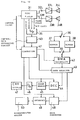
- Fig. 10 is a block diagram showing an apparatus for playback of disc according to an embodiment of this invention.
- Figs. 11 to 13 are schematic diagrams of the playback apparatus for use with a disc of the type shown in Fig. 10 according to the present invention.
- Referring to Figs. 1 and 2, a typical data construction will be described in case of audio data being stored in a compact disc.
- Fig. 1 illustrates a data stream as stored in the compact disc. One frame consists of 588 bits of data to be recorded and includes a frame synchronizing pulse FS of a particular bit pattern which is followed by the first direct-current component constraint bits group RB consisting of 3 bits. Following these, the 0th to 32nd groups of data bits DB, each consisting of 14 bits, and groups of direct-current component constraint bits RB, each consisting of 3 bits, are provided alternately. The 0th data bits DB constitute a subcoding signal or user's bits which serves for controlling disc playback or for indicating related information. The 1st to 12th and 17th to 28th groups of data bits DB are allocated to audio data in a main channel, and the rest, 13th to 16th and 29th to 32nd groups of data bits DB are allocated to parity data for error correction of the main channel. Each group of data bits DB has 14 bits of data which have been converted during recording from 8 bits of data by an 8-14 modulation technique (EFM).
- Fig. 2 shows a reproduced block consisting of 98 parallel successive frames in which each group of data bits DB is converted back to 8 bits and each set of direct current component constraint bits RB is excluded. In the first two frames, the subcoding signals P to W constitute synchronizing patterns having particular bit patterns. With respect to the Q-channel, the last 16 of the 98 frames constitute an error detection CRC code.
- The P-channel is a flag indicating whether the frame is a pause or music, a high level indicating a pause, a low level indicating music and a 2 Hz pulse indicating a lead-out section, so that the detecting and counting the P-channel bits makes the selection of a designated musical piece possible. The Q-channel performs similar but more complicated control. Specifically, the Q-channel information can be supplied to a microprocessor built into the disc playback apparatus to allow random music selection to reproduce another music track immediately after reproducing the currently selected music track. The remaining channels R through W constitute regions for data indicating the songwriter, composer, text and explanation of the music recorded on the disc by means of a display or voice.
- Concerning the Q-channel, the first 2 bits serve as part of the synchronizing signal pattern, the next 4 bits serve as control bits, the following 4 bits serve as address bits, the subsequent 72 bits serve as data bits, and the final 16 bits serve as a CRC code.
- In a lead-in track, the last 96 bits of the Q-channel are defined as a data construction as shown in Fig. 3A. The control bits of 1st to 4th bits and address bits of 5th to 8th bits are followed by 72 bits of data. The data bits include a track number code TNR of 8 bits in two 4 bit portions which vary to represent the decimal members from 0 to 9 so that the track number code TNR varies from 00 to 99. The track number TNR is 00 in the lead-in track. The 8 bits following the track number bits represent a pointer. The 4 bits following the pointer represent minutes (MIN) data, the 4 bits following the minutes data represent seconds (SEC) data and the 4 bits following the seconds data represent frames data (75 frames equivalent to one second). The 8 bits following the 49th bit are set as all 0 and subsequent every 4 bits represent minutes, seconds and frames data of the point.
- In the lead-in track and musical program area is stored data of minutes, seconds and frames which vary with time from zero minutes, zero seconds and zero frames to the lead-in track or to the end of a musical program. The lead-in track stores TOC (Table Of Contents) data enumerating what is stored in the disc and consists of a pointer and minutes, seconds and frames data. That is, the values of minutes, seconds and frames of the starting point of each musical program bearing a particular track number together with the value of the pointer, constitute the data in the Q-channel of the lead-in track.
- When the pointer value is AO (hexadecimal-notation), the minutes data, indicated as P-MIN, represents the track number of a first musical program in the disc, and both the data of seconds and frames are zero. If the pointer value is A1, the minute data represents the track number of the last musical program in the disc, and both the data of seconds and frames are zero. If the pointer value is A2, the minutes, seconds and frames data represent the starting point of a lead-out track.
- As described above, the lead-in track stores the data in the Q-channel but does not store the stereo musical data in the main channel. Likewise, the lead-out track does not store stereo musical data. The standards for the prior art compact disc allow the presence of a maximum of 4 bits of data including the last bit of a 16-bits data.
- Fig. 3b illustrates an arrangement of data in the Q-channel in the program area. The first 4 bits constitute the control bits, the next 4 bits following the control bits constitute the address bits. The following 8 bits represent the track number TNR. As previously stated, the track number TNR of the lead-in track is 00. The track numbers TNR of the musical program area can take any value from 01 to 99. The track number TNR of the lead-out track is AA. The lead-out track starts from the end point of the last musical program stored in the disc.
- The 8 bits following the track number TNR represent an index X. The index X serves to separate each musical program and increases incrementally from 01 to maximum 99. In a pause section, the index always contains 00. Minutes, seconds and frames data following the index X represents the time-elapsed of the musical program or pause. All of minutes (A MIN), seconds (A SEC) and frames (A FRAME) data following the all-zero 8 bits constitutes an absolute time data representing the time-elapsed from the very beginning of the musical program area to the end of the lead-out track. The data stored in the compact disc are accessible by reference to the absolute time code.
- The control bits in the Q-channel are defined as shown in Fig. 3C. In Fig. 3C, the symbol X represents a non-defined bit and may be either 0 or 1. Control bits (00X0) mean a non-preemphasized 2-channel audio data. Control bits (10XX) and (01X1) are not yet defined. Control bits (01X0) mean that the disc stores digital data such as still picture data. Control bits (XX0X) mean inhibition of reproduction of the non-audio digital data, and control bits (XX1X) mean allowance of reproduction of the non-audio digital data. In one embodiment of this invention, a disc storing both stereo musical data and other digital data has control bits (01X1).
- Referring to Fig. 4, a prior art compact disc storing such stereo musical data and subcoding signals as mentioned above will be described.
- In Fig. 4, the
reference numeral 1 designates a prior art compact disc, and thereference numeral 2 designates a central hole therein. Thecompact disc 1 is applied with a reproducing laser beam from its underside, and plays back from the inner periphery towards the outer periphery thereof. The diameter of thecentral hole 2 is 15mm. Thereference numeral 3 designates a clamping area (having a radial range of 26 mm to 33 mm) where thecompact disc 1 is supported, when thecompact disc 1 is inserted into the player. Thereference numeral 4 designates the program area (having a radial range of 50 mm to 116 mm), thereference numeral 5 designates an information area (having a radial range of 45 mm to 118 mm). The starting point 6 (at a maximum radius of 46 mm) of the lead-in text is located radially inward of theprogram area 4 but within theinformation area 5. The final lead-outpoint 7 is located radially outward of theprogram area 4 within theinformation area 5. - A disc according to an embodiment of the invention has the same thickness and diameter as a conventional
compact disc 1 and stores both stereo musical data and other digital data as the main channel data. The arrangement of data in the P-channel and Q-channel of the subcoding signals in the disc of this invention are the same as in the conventional compact disc. - The Fig. 5 illustrates the recording format of the digital data. Each digital data comprises 2352 bytes (=588 x 4 bytes) as a one block unit. In Fig. 5, the left channel and right channel as described indicate correspondence to the sampling data of the left and right channels of stereo musical data. In case of stereo musical data, as above described, since 24 (= 6 x 2 x 2) bytes of data is recorded within the period defined by consecutive frame synchronizing signals, if other digital data is recorded in the same format (referring to Fig. 1) as for stereo musical data, the data of one block (2352 bytes) is recorded on from the 0th to 97th frames. Accordingly, the digital data can be recorded without disrupting the 98-frame cycle of the variation of the subcoding signals.
- The first byte of the digital data of one block is all zeros and the next ten bytes are all ones, followed finally by another byte of zeros. These 12 bytes constitute a header indicating the beginning of one block of digital data. The header is followed by minutes data, seconds data, sector data and mode data each of one byte. The minute, second and sector bytes specify one block address, with the 75 sectors counting one second similar to 75 frames. The mode data indicates the kinds of digital data in still picture data other than the header, address (minutes, seconds, sector) and mode.
- According to some embodiments of this invention, examples of discs storing both digital stereo musical data and other digital data will now be described, referring to Figs. 6 to 9.
- A
disc 11 shown in Fig. 6 includes ageneric information area 21 in which aninformation area 5 is located at a range from the inner point thereof to the predetermined outer point thereof. The digital stereo musical data is stored in afirst program area 4 within theinformation area 5. A first lead-in track starting from apoint 6 is located radially inward of thefirst program area 4. A lead-out track is located radially inward of the final lead-outpoint 7 but radially outside of thefirst program area 4. Subcoding signals stored in the first lead-in track and the first lead-out track and thefirst program area 4 of the disc of this invention are similar to those in the prior art compact disc. However, the control bits of the data in the Q-channel stored in the first lead-in track (track number TNR=00) are (01X1) which indicates that the disc stores both digital stereo musical data and other digital data. - Reading this control data by a disc playback apparatus, the playback starting point jumps to the starting point of the first lead-out track, and the track number TNR=AA of the first lead-out track is neglected so as to control the playback of the disc and to playback up to the tracks in the outer periphery of the disc.
- A
second program area 23 is located outside a second lead-inarea 22 which is located outside of theinformation area 5 within thegeneric information area 21. A second lead-out track is located outside of thesecond program area 23 but inside of a second final lead-out limit 24. Thesecond program area 23 stores digital data, for example, still picture data as shown in Fig. 5. The second lead-inarea 22 and the second lead-out track store the subcoding signals of the Q-channel as shown in Fig. 3B. The track number TNR of the second lead-inarea 22 is AD and the track number TNR of the second lead-out track is AE. - The second lead-in
area 22 stores the necessary control information for playing thedisc 11. The disc playback apparatus reproduces the first andsecond program areas - Fig. 7 illustrates a
disc 12 according to a second embodiment of this invention. Ageneric information area 21 of thedisc 12 comprises asecond program area 23 wider than thefirst program area 4 so as to mainly store the non-audio digital data. Thefirst program area 4 stores digital audio data representing a spoken notice e.g. "This disc is not intended for music and cannot be played." - in Chinese, Japan, English, German and/or French. This notice is convenient to prevent misunderstanding that the player is damaged, when the disc storing the other digital data is played on a conventional disc player which would ignore recognition data in the Q-channel of the first lead-in track of the present invention. However, the disc playback apparatus according to this invention, which is capable of playing other digital data stored in thesecond program area 23 of thedisc 12, can be signalled not to playback the notice by means of the control information stored in the second lead-inarea 22. - Fig. 8 shows a
disc 13 serving mainly to playback digital stereo musical data similar to thedisc 11 of Fig. 6. The starting point 25 of the second lead-in track is located radially inward of thestarting point 6 of the first lead-in track. Thestarting points 6 and 25 delimit the second lead-inarea 22. - This second lead-in
area 22 stores as data in the Q-channel the control bits (01X1) indicating that thedisc 13 stores both digital music data and the other digital data. The initial, inner tracks of thesecond program area 23 of thedisc 13 store control information instructing how to playback the first andsecond program areas - Fig. 9 illustrates a
disc 14 serving mainly to playback the other digital data similar to thedisc 12 of Fig. 7. Thefirst program area 4 of thedisc 14 stores a notice spoken in several languages announcing that thedisc 14 is not for reproducing music. The first lead-in area is located radially inward of thefirst program area 4 and start at thestarting point 6 of the first lead-in track. The second lead-inarea 22 is located radially inward of the first lead-in area and start at the starting point 25 of the second lead-in track. - The
discs - An embodiment of the disc playback apparatus of this invention will be described, referring to Fig. 10. In Fig. 10, the
reference numeral 31 designates a disc player. Stereo music signal reproduced by thedisc player 31 are outputted atoutput terminals output terminals disc player 31 are respectively supplied with left-channel and right-channel signals of the reproduced stereo signal. The audio signals in the respective left-channel and right-channel are supplied to left-side and right-side speakers amplifiers - If the disc being reproduced by the
disc player 31 stores solely digital data other than stereo musical data, the reproduced data from this disc is supplied to a serial-parallel converter 35, which receives frame pulses and a bit clock signal both synchronized with the reproduced data from thedisc player 31 and outpuuts 8-bit parallel data as symbols. The parallel data are alternately written intobuffer memories input switch 36. A control-data separating circuit 40 is provided, relating to the serial-parallel converter 35. - The reference numeral 41 designates a controller including a microcomputer. The controller 41 receives control data from the control-
data separating circuit 40 and the subcoding signals from thedisc player 31. The Q-channel of the subcoding signals includes a recognition code (control bits) indicating that the disc stores both stereo musical signals and the other digital data. The controller 41 generates a control signal to be supplied to thedisc player 31 so as to control switching of the reproducing output signal path in accordance with the recognition code. - Contents of the
buffer memories output switch 39 and supplied to a DMA (direct memory access)controller 42 which is controlled by the controller 41. - The output from the
DMA controller 42 is supplied to adata selector 43 which is controlled by the controller 41 and distributes the output data from theDMA controller 42 to different circuits in accordance with the mode of still-picture, digital data (game program etc.). In the still picture mode, output data from thedata selector 43 is written into aframe memory 45 via adecoder 44 for colored-picture data consisting of Y,U and V components. The controller 41 controls the operation of thedecoder 44 and theframe memory 45. The single-frame still picture data read out from theframe memory 45 is converted to analog color video signals by a D/A converter 46 and supplied to a CRT (cathod ray tube)display 47. - In the game program mode, the output data from the
data selector 43 is supplied to adata converter 48 and convetered into serial data in a predetermined format, and is supplied to amicrocomputer system 50 through aninterface 49. - The operation of the above-mentioned disc playback apparatus will be described, for example, when the
disc 11 of Fig. 6 is applied thereto. As shown in Fig. 11A, for the example,thefirst program area 4 of thedisc 11stores 4 musical selections M1, M2, M3 and M4 separated by pause sections respectively, and thesecond program area 23 of thedisc 11 stores single-frame still picture data D1, D2, D3 and D4 respectively corresponding to the musical selections M1, M2, M3 and M4. - When the
disc player 31 reproduces the first lead-in track from thestart point 6, the TOC data in the Q-channel of the subcoding signals are reproduced and supplied to to a system controller (not shown) of thedisc player 31 and the controller 41. Provided that the control bits in the Q-channel show (01X1), a pickup of thedisc player 31 jumps over theprogram 4 is shown in Fig. 11B without reproducing it and to resume reading operation from the starting point of the first lead-out track. - After the first lead-out track is reproduced, the
disc player 31 reproduces the second lead-inarea 22 and then supplies the controller 41 through the serial-parallel conveter 35 and a control-data separating circuit 40 with control data DR reproduced from the second lead-inarea 22. Then, the first still picture data D1 is reproduced. The address data and mode data of the first still picture data D1 are supplied to the controller 41 through the serial-parallel converter 35 and the control-data separating circuit 40 and the reproduced digital data is supplied to thedecoder 44 by thedata selector 43. The still picture data D1 are written into theframe memory 45 through thebuffer memory DMA controller 42, thedata selector 43 and thedecoder 44. In the case where the TOC data of the first lead-in area is reproduced first, a muting operation is performed so as to suppreass audio output during reproduction of the second lead-inarea 22 and thesecond program area 23. - As shown in Fig. 11B, after completing the reproduction of the still picture data D1, the pick up returns to the starting point of the first musical selection M1 and starts to reproduce it. In this case, the still picture data D1, as shown in Fig. 12, will be repeatedly read out from the frame memory so as to display still picture on the
CRT display 47. Thus, the still picture reproduced by theCRT display 47 can be watched while listening to the the first musical selection M1. As shown in Fig. 11B, upon completion of reproducing the first piece M1, the pick up is quickly returned to the outer periphery of thedisc 11 and then starts reproducing the still picture data D2 of thesecond program area 23. The TOC data of the first lead-in area or the control data of the second lead-inarea 22 indicates where the still picture data D1 to D4 are stored in thesecond program area 23. - The reproduced still picture data D2 is treated like the still picture data D1 and as shown schematically in Fig. 12, the music M2 is reproduced from the
speakers CRT display 47. Likewise, the still picture data D3, the music selection M3, the still picture data D4 and the music selection M4 are sequentially reproduced. When the second lead-out area after the last music selection M4 is reproduced, completion of all of the program data is recognized and its reproducing operation is stopped. - The music data stored in the
disc 11 can be reproduced by prior art disc playback apparatus capable of reproducing only stereo music. That is, reproduction of the first lead-in track is started from thestart point 6 of thedisc 11, and the TOC data is reproduced. Even if the control bits in the Q-channel in the first lead-in track is encoded as (01X1), the control bits are not decoded by the prior art disc playback apparatus as they are not recognized so the data is neglected. Therefore, the music selection M1, M2, M3 and M4 following the first lead-in track are sequentially reproduced. Completion of the first lead-out track is regarded as completion of all of the program data and its reproducing operation is stopped. Accordingly, the area outside of the first lead-out track is not reproduced so as to prevent noise from generating due to reproduction of the control data DR and still picture data D1 to D4. - The data on the
discs - Furthermore, the disc playback apparatus of Fig. 10 can be employed to playback the discs storing only stereo music as well as the discs storing only the other digital data. Namely, the control bits in the Q-channel reproduced from the first lead-in area works for switching of the reproduced signal processing circuit and for muting of reproducing system of audio data.
- This invention is also applicable to magnetic discs and electrostatic capacitance discs.
- According to this invention, it is realized to provide discs from which stereo music is reproduced without generating large noise due to reproduction of non-audio digital data, when it is applied to a prior art disc playback apparatus for playback of the conventional disc storing music data only. Discs according to this invention make simultaneous reproduction of stereo music data and still picture possible. In addition, since digital data is recorded on the outer area of the disc, the waiting time to start reproducing stereo music data can be miminized.
- According to this invention, it is possible to playback the discs storing both first digital data and second digital data as well as to prevent noise from generating due to digital data other than audio data being reproduced on a conventional player. In this invention since it is determined by recognition data whether the data stored in the disc is both of the first digital data and the second digital data or the first digital data only, prior art disc storing the first digital data only can be reproduced without trouble.
Claims (13)
- A disc storing data of a first kind in a first annular area (4) bounded by a first lead-in track (6) and a first lead-out track (7), and to be reproduced in a direction from the first lead-in track (6) towards the first lead-out track (7), characterized in that a second annular area (23) succeeds, in said direction of reproducing, the first annular area (4) and stores data of a second kind and in that recognition data for distinguishing the disc containing both said first and second kinds of data from a conventional type of disk containing only the first kind of data, is recorded in a track preceding, in the direction of reproducing, the first annular area.
- A disc according to claim 1 wherein the first lead-in track contains said recognition data and a second lead-in track (22) for said second annular area (23) succeeds the first lead-out track (7) and contains control data for controlling the operational mode for reproducing the disk.
- A disc according to claim 1 wherein a second lead-in track (22), for said second annular area (23), precedes the first lead-in track (6) and contains said recognition data and the second annular area (23) contains control data for controlling the operational mode for reproducing the disk.
- A disc according to claim 1, 2 or 3, characterized in that said first kind of data (4) includes digital audio data.
- A disc according to any one of the preceding claims, characterized in that said second kind of data (23) includes digital video data.
- A disc according to any one of claims 1 to 4, characterized in that said second kind of data (23) includes computer program data.
- A disc playback apparatus capable of playing a disc having a first recording region (4) for storing a first type of data signal, a second recording region (23) succeeding the first recording region (4) and for storing a second type of data signal, a lead-in region (6) preceding the first recording region (4) and for storing an identifying data signal for indicating the presence of the second recording region (23), characterised in that it comprises:
pick-up means for obtaining a reproduction signal from the disc;
a first reproduction processing circuit for reproducing the first type of data signal;
a second reproduction processing circuit (35-40, 42-46, 48-49) for reproducing the second type of data signal; and
a control circuit (41) supplied with the identifying data signal and for outputting a signal controlling the operation of said pickup means and said first and second reproduction processing circuits (31; 35-40, 42-46, 48-49); characterised in that
the disc has a lead-out region (7) between the first recording region (4) and the second recording region (23) and for storing an end data signal for indicating the end of the first recording region (4); and
said control circuit (41) controls said pickup means so as to move, after reading the lead-in region (6) and when the identifying data signal indicates the presence of the second recording region (23) to the second recording region (23) and then to return to the first recording region (4). - A disc playback apparatus according to claim 7, wherein said control circuit (41) is adapted to control said pickup means so as to reproduce the first recording region (23) when the identifying data signal indicates the absence of the second recording region (23) after reading the lead-in region (6).
- A disc playback apparatus according to claim 7 or 8 wherein the identifying data signals are encoded in a sub-channel and inhibit output to one of said first and second reproduction processing circuits (31; 35-40, 42-46, 48-49).
- A disc playback apparatus according to claim 7, 8 or 9 wherein the second type of data signal includes a control signal for controlling operation of said pickup means and said control circuit (41) is supplied with the control signal.
- A disc playback apparatus according to claim 7, 8, 9 or 10 wherein the first type of data signal includes digital audio data and said first reproduction processing circuit (31) includes a reproducing circuit for reproducing an audio signal.
- A disc playback apparatus according to claim 7, 8, 9, 10 or 11 wherein the second type of data signal includes video data and said second reproduction processing circuit (31; 35-40, 42-46, 48-49) includes a reproducing circuit (47) for reproducing a video signal.
- A disc playback apparatus according to claim 7, 8, 9, 10 or 11 wherein the second type of data signal includes computer program data and said second reproduction processing circuit (31; 35-40, 42-46, 48-49) includes a computer system (50).
Applications Claiming Priority (2)
| Application Number | Priority Date | Filing Date | Title |
|---|---|---|---|
| JP58226598A JPH0828054B2 (en) | 1983-11-30 | 1983-11-30 | Disk-shaped recording medium |
| JP226598/83 | 1983-11-30 |
Publications (3)
| Publication Number | Publication Date |
|---|---|
| EP0165320A1 EP0165320A1 (en) | 1985-12-27 |
| EP0165320A4 EP0165320A4 (en) | 1988-03-07 |
| EP0165320B1 true EP0165320B1 (en) | 1992-06-03 |
Family
ID=16847695
Family Applications (1)
| Application Number | Title | Priority Date | Filing Date |
|---|---|---|---|
| EP85900170A Expired - Lifetime EP0165320B1 (en) | 1983-11-30 | 1984-11-30 | Disk-shaped recording medium and apparatus for reproducing the same |
Country Status (11)
| Country | Link |
|---|---|
| US (1) | US4893193A (en) |
| EP (1) | EP0165320B1 (en) |
| JP (1) | JPH0828054B2 (en) |
| KR (1) | KR950001871B1 (en) |
| AT (1) | ATE76996T1 (en) |
| AU (1) | AU587963B2 (en) |
| BR (1) | BR8407199A (en) |
| DE (1) | DE3485761T2 (en) |
| HK (1) | HK81595A (en) |
| SG (1) | SG26397G (en) |
| WO (1) | WO1985002481A1 (en) |
Cited By (1)
| Publication number | Priority date | Publication date | Assignee | Title |
|---|---|---|---|---|
| CN1901068B (en) * | 1995-01-30 | 2011-03-02 | 索尼公司 | Disc-shaped recording medium |
Families Citing this family (91)
| Publication number | Priority date | Publication date | Assignee | Title |
|---|---|---|---|---|
| US4949326A (en) * | 1986-12-10 | 1990-08-14 | Matsushita Electric Industrial Co., Ltd. | Optical information recording and reproducing system using optical disks having an error correction function |
| JPH0634304B2 (en) * | 1983-09-01 | 1994-05-02 | ソニー株式会社 | Disk playback device |
| DE3485541D1 (en) * | 1983-12-16 | 1992-04-09 | Sony Corp | DEVICE FOR DISK PLAYBACK. |
| JPH0685275B2 (en) * | 1986-01-27 | 1994-10-26 | キヤノン株式会社 | Playback device |
| US4761692A (en) * | 1986-04-15 | 1988-08-02 | Pioneer Electronic Corporation | Method and apparatus for data recording disc playback |
| US4843484A (en) * | 1986-09-12 | 1989-06-27 | Pioneer Electronic Corporation | Information recording disc with composite index codes and its playback method |
| JPS6377280A (en) * | 1986-09-20 | 1988-04-07 | Pioneer Electronic Corp | Initial setting system in still picture recording and reproducing device |
| DE3786531T2 (en) * | 1986-09-30 | 1994-02-03 | Pioneer Electronic Corp | Method and device for reproducing optical disks with sound as well as sound and picture information. |
| JPS63155475A (en) * | 1986-12-19 | 1988-06-28 | Pioneer Electronic Corp | Reproducing method for disk reproducing device |
| US4872068A (en) * | 1987-01-28 | 1989-10-03 | Pioneer Electronic Corporation | Disk playing method resulting in reduced start-up time |
| EP0278133A1 (en) * | 1987-02-09 | 1988-08-17 | Industrial Technology Research Institute | Features expander for CD player connected with microcomputer and TV set |
| JPH0670876B2 (en) * | 1987-02-10 | 1994-09-07 | ソニー株式会社 | Optical disc and optical disc reproducing apparatus |
| EP0291028B1 (en) * | 1987-05-15 | 1997-01-08 | Canon Kabushiki Kaisha | Reproducing apparatus |
| FR2616952B1 (en) * | 1987-06-22 | 1991-04-19 | Mpo Disques Sa | INSTALLATION FOR REPRODUCING DATA FROM AN OPTICAL DISC |
| FR2617352B1 (en) * | 1987-06-26 | 1989-12-01 | Eduvision Sa | METHOD FOR ENCODING COMPUTER DATA FOR TRANSMISSION TO VIDEO STANDARDS, VIDEODISC IMPLEMENTING SAID METHOD AND INTERFACE FOR OPERATING SUCH A VIDEODISK |
| JPH0664839B2 (en) * | 1987-08-25 | 1994-08-22 | 富士通テン株式会社 | Disk playback device |
| US5093750A (en) * | 1987-11-06 | 1992-03-03 | Samsung Electronics Co., Ltd. | System for recording/reproducing video data on or from a tape medium for storing digital signals and method therein |
| EP0347511A3 (en) * | 1987-11-19 | 1990-11-14 | Kurt Matthys | Video disc with a supplementary audio and signal track |
| EP0325325B1 (en) * | 1988-01-19 | 1996-09-04 | Koninklijke Philips Electronics N.V. | System for transferring information using an information carrier |
| JP2706076B2 (en) * | 1988-01-29 | 1998-01-28 | シャープ株式会社 | Optical disk recording and playback system |
| JP2524795B2 (en) * | 1988-02-12 | 1996-08-14 | パイオニア株式会社 | Disc playback device |
| JPH01273275A (en) * | 1988-04-25 | 1989-11-01 | Pioneer Electron Corp | Picture information recording and reproducing system |
| JP2851850B2 (en) * | 1988-04-25 | 1999-01-27 | パイオニア株式会社 | Recording and playback method of image information |
| JPH01273268A (en) * | 1988-04-25 | 1989-11-01 | Pioneer Electron Corp | Information recording and reproducing method |
| US5282186A (en) * | 1988-04-25 | 1994-01-25 | Pioneer Electronic Corporation | Method and apparatus for recording and reproducing picture information and recording medium |
| JPH01273270A (en) * | 1988-04-25 | 1989-11-01 | Pioneer Electron Corp | Performance system and information recording and reproducing system in recording medium performance instruments |
| JP2778051B2 (en) * | 1988-10-20 | 1998-07-23 | ソニー株式会社 | Disk recording device |
| JP2584040B2 (en) * | 1989-01-06 | 1997-02-19 | 松下電器産業株式会社 | Information signal recording method and information signal recording disk |
| US5130969A (en) * | 1989-02-15 | 1992-07-14 | Sony Corporation | Apparatus having defective sector compensation coupled with analog information mode and digital information mode recording/reproducing capability |
| US5267097A (en) * | 1989-03-06 | 1993-11-30 | Hitachi, Ltd. | Information transfer control system having rotary storage unit which uses a pseudo address mark |
| EP0389689B1 (en) * | 1989-03-28 | 1997-06-04 | POLYGRAM MANUFACTURING & DISTRIBUTION CENTRES GMBH | Method for transmitting a transmission signal and a transmitting device and a receiving device for use in the method |
| JP2578973B2 (en) * | 1989-05-01 | 1997-02-05 | パイオニア株式会社 | Compatible disc player with on / off track detection function |
| JP3060460B2 (en) * | 1989-05-15 | 2000-07-10 | ソニー株式会社 | Disk, disk recording device, and disk recording / reproducing device |
| JPH03119574A (en) * | 1989-10-02 | 1991-05-21 | Sony Corp | Recording information generating method |
| US5132955A (en) * | 1990-01-02 | 1992-07-21 | Sonics Associates, Incorporated | Method and apparatus for synchronizing multiple cd players |
| JP2844783B2 (en) * | 1990-01-09 | 1999-01-06 | ソニー株式会社 | Disc playback device |
| EP0440224B1 (en) * | 1990-02-01 | 1996-04-03 | Matsushita Electric Industrial Co., Ltd. | Data playback apparatus for realizing high transfer rate |
| JPH03288360A (en) * | 1990-04-04 | 1991-12-18 | Pioneer Electron Corp | Composite disk playing method |
| JP2801372B2 (en) * | 1990-06-28 | 1998-09-21 | キヤノン株式会社 | Signal processing system, device and storage device |
| JPH04105269A (en) * | 1990-08-24 | 1992-04-07 | Sony Corp | Disk, disk recorder, and disk reproducing device |
| JP3141242B2 (en) * | 1990-08-24 | 2001-03-05 | ソニー株式会社 | Optical disk recording device |
| JPH04141858A (en) * | 1990-10-01 | 1992-05-15 | Sony Corp | Disk reproduction device |
| CA2054880C (en) * | 1990-11-09 | 1997-07-08 | Shigemi Maeda | Information recording and reproducing device |
| FR2670315A1 (en) * | 1990-12-10 | 1992-06-12 | Ginocchio Pierre | Process for reading text, images, software and sounds on an "AUDIO COMPACT DISC" or a "VIDEO DISC" |
| US5878019A (en) * | 1991-04-02 | 1999-03-02 | U.S. Philips Corporation | Record carrier having at least two information volumes |
| US5684786A (en) * | 1991-04-02 | 1997-11-04 | U.S. Philips Corporation | Record carrier having an information volume including audio information and an information volume including additional non-audio information |
| DE4122080A1 (en) * | 1991-07-04 | 1993-01-07 | Thomson Brandt Gmbh | Determination of fault location on compact disc - counting frame pulses before and after fault limits within sub-code time block |
| ATE157795T1 (en) * | 1991-07-05 | 1997-09-15 | Philips Electronics Nv | AUDIO STORAGE MEDIUM AND PLAYBACK DEVICE FOR PLAYING A STORAGE MEDIUM |
| US5363250A (en) * | 1991-07-31 | 1994-11-08 | U.S. Philips Corporation | Prerecorded record carrier |
| US5349349A (en) * | 1991-09-30 | 1994-09-20 | Sony Corporation | Modulator circuit for a recording for a digital recording medium |
| US5414684A (en) * | 1992-01-24 | 1995-05-09 | Pioneer Electronic Corporation | Method and apparatus for discriminating type of disks positioned on a CD player |
| JPH06187732A (en) * | 1992-12-15 | 1994-07-08 | Sony Corp | Magneto-optical disk device and magneto-optical disk |
| US5687397A (en) * | 1993-02-26 | 1997-11-11 | Sony Corporation | System for expansion of data storage medium to store user data |
| JP3463352B2 (en) * | 1993-07-23 | 2003-11-05 | ソニー株式会社 | Playback device |
| EP0644692B2 (en) * | 1993-09-16 | 2003-10-01 | Kabushiki Kaisha Toshiba | Video signal compression/decompression device for video disk recording/reproducing apparatus |
| US5850500A (en) * | 1995-06-28 | 1998-12-15 | Kabushiki Kaisha Toshiba | Recording medium comprising a plurality of different languages which are selectable independently of each other |
| US5630006A (en) * | 1993-10-29 | 1997-05-13 | Kabushiki Kaisha Toshiba | Multi-scene recording medium and apparatus for reproducing data therefrom |
| DE69318038T2 (en) * | 1993-10-29 | 1998-10-29 | Toshiba Kawasaki Kk | RECORDING MEDIUM THAT CAN PROCESS DIFFERENT LANGUAGES AND PLAYBACK DEVICE |
| US5764846A (en) * | 1993-10-29 | 1998-06-09 | Kabushiki Kaisha Toshiba | Multi-scene recording medium and apparatus for reproducing data therefrom |
| JP3235706B2 (en) * | 1994-05-31 | 2001-12-04 | 三星電子株式会社 | Recording method of disk recording medium and reproducing method thereof |
| JPH0845246A (en) * | 1994-07-29 | 1996-02-16 | Sony Corp | Recording medium, reproducing method, recording device and reproducing device |
| US5602815A (en) * | 1994-08-09 | 1997-02-11 | Wea Manufacturing, Inc. | Method and apparatus for combining CD-ROM data and digital audio on a single disc |
| TW250565B (en) * | 1994-10-20 | 1995-07-01 | Digital Audio Disc Corp | Mass production of multisession discs |
| US5740435A (en) * | 1994-10-31 | 1998-04-14 | Sony Corporation | Data management apparatus and method for managing data of variable lengths recorded on a record medium |
| US5778142A (en) * | 1994-11-24 | 1998-07-07 | Kabushiki Kaisha Toshiba | Large capacity recording medium, method and apparatus for reproducing data from a large-capacity recording medium, and method and apparatus for recording data on a large-capacity recording medium |
| SG38892A1 (en) * | 1994-12-22 | 1997-04-17 | Sony Corp | A recording medium having a first management area for managing a first attribute and a second management area for managing a second attribute of a program recorded in |
| AU728279C (en) * | 1995-01-30 | 2001-08-16 | Sony Corporation | Disc-shaped recording medium, recording apparatus and reproducing apparatus |
| FR2732497B1 (en) * | 1995-04-03 | 1997-05-30 | Ambre Sarl | METHOD FOR RECORDING DIGITAL AUDIO INFORMATION AND TEXTS OR DOCUMENTS ON THE SAME OPTICAL DISC RECORDING MEDIUM |
| US5778136A (en) * | 1995-06-15 | 1998-07-07 | Kabushiki Kaishi Toshiba | Multi-scene recording medium wherein related data segments of simultaneously proceeding scenes are recorded alternatingly and continuously thereon |
| US5751672A (en) | 1995-07-26 | 1998-05-12 | Sony Corporation | Compact disc changer utilizing disc database |
| JP3707137B2 (en) * | 1996-07-04 | 2005-10-19 | ソニー株式会社 | Recording medium and playback device |
| KR0174713B1 (en) * | 1996-07-13 | 1999-04-15 | 삼성전자주식회사 | Cd-rom synthetically control apparatus for computer system and method of controlling the same |
| JPH10341402A (en) * | 1997-06-09 | 1998-12-22 | Sony Corp | Image record device and method and image reproducing device and method |
| DE59808816D1 (en) * | 1998-02-19 | 2003-07-31 | Micronas Gmbh | Audio player |
| EP0992996A3 (en) * | 1998-10-08 | 2002-04-24 | Sony Corporation | Reproduction apparatus and method |
| JP2000123549A (en) | 1998-10-13 | 2000-04-28 | Sony Corp | Reproducer and recorder |
| US20020048224A1 (en) * | 1999-01-05 | 2002-04-25 | Dygert Timothy W. | Playback device having text display and communication with remote database of titles |
| DE19931879A1 (en) | 1999-07-09 | 2001-01-18 | Micronas Gmbh | Integrator |
| DE59913598D1 (en) | 1999-07-15 | 2006-08-03 | Micronas Gmbh | Playback device |
| JP3566152B2 (en) | 1999-10-27 | 2004-09-15 | 松下電器産業株式会社 | Data recording / reproducing device and program recording medium |
| CA2366576A1 (en) * | 2000-02-10 | 2001-08-16 | Sony Corporation | Method for recording and/or reproducing data on/from recording/recorded medium, reproducing apparatus, recording medium, method for recognizing recording/recorded medium, and method for recording and/or reproducing data for apparatus using recording/recorded medium |
| US7092340B2 (en) | 2000-07-13 | 2006-08-15 | Micronas Gmbh | Playback apparatus |
| WO2002017135A1 (en) | 2000-08-23 | 2002-02-28 | Koninklijke Philips Electronics N.V. | Method of enhancing rendering of a content item, client system and server system |
| JP2002150675A (en) | 2000-11-06 | 2002-05-24 | Sony Corp | Method and device for recording, method and device for reproducing, and storage medium |
| US20060134038A1 (en) * | 2002-09-06 | 2006-06-22 | De La Poterie Valerie | Make-up composition for keratin fibres such as eyelashes |
| US20060099231A1 (en) * | 2002-09-06 | 2006-05-11 | De La Poterie Valerie | Make-up composition for keratin fibres such as eyelashes |
| JP2004127387A (en) * | 2002-09-30 | 2004-04-22 | Mitsumi Electric Co Ltd | Optical disk device, and method for initializing optical disk |
| JP4075744B2 (en) * | 2003-02-12 | 2008-04-16 | 日産自動車株式会社 | Fuel tank mounting structure |
| US20050069508A1 (en) * | 2003-08-06 | 2005-03-31 | Karl Pays | Cosmetic composition comprising a dispersion of at least one wax in at least one volatile oil |
| WO2005045837A1 (en) * | 2003-11-10 | 2005-05-19 | Matsushita Electric Industrial Co., Ltd. | Recording/reproducing apparatus, recording/reproducing method, and controller |
| US7659579B2 (en) * | 2006-10-06 | 2010-02-09 | International Business Machines Corporation | FETS with self-aligned bodies and backgate holes |
Family Cites Families (20)
| Publication number | Priority date | Publication date | Assignee | Title |
|---|---|---|---|---|
| US4065795A (en) * | 1975-12-04 | 1977-12-27 | Westinghouse Electric Corporation | Recording technique for an audio/video program wherein the audio incorporates video change signals |
| GB1577133A (en) * | 1976-03-19 | 1980-10-22 | Rca Corp | Video information record and playback apparatus |
| JPS5528579A (en) * | 1978-08-22 | 1980-02-29 | Sony Corp | Signal recording/reproducing method |
| US4229808A (en) * | 1978-12-21 | 1980-10-21 | Ncr Corporation | Method for recording multiple data segments on a storage disc with eccentricity factor |
| CA1145464A (en) * | 1979-08-22 | 1983-04-26 | Wayne R. Dakin | Programmed video record disc and related playback apparatus |
| JPS5730476A (en) * | 1980-07-29 | 1982-02-18 | Pioneer Video Corp | Recording and reproduction system for video disk |
| JPS5737777A (en) * | 1980-08-19 | 1982-03-02 | Victor Co Of Japan Ltd | Reproducing device for rotary information recording medium |
| JPS5748881A (en) * | 1980-09-08 | 1982-03-20 | Pioneer Electronic Corp | Video format signal recording and playback system |
| JPS5848279A (en) * | 1981-09-14 | 1983-03-22 | Sony Corp | Cue signal processor |
| JPS5864603A (en) * | 1981-10-13 | 1983-04-18 | Toshiba Corp | Reproduction system of video disk |
| EP0084777B1 (en) * | 1982-01-25 | 1986-04-09 | Discovision Associates | Recovering and playing back selected audio messages from a block of messages on a recording medium |
| JPS58133690A (en) * | 1982-02-02 | 1983-08-09 | Sony Corp | Disc reproducer |
| JPS58137138A (en) * | 1982-02-05 | 1983-08-15 | Sanyo Electric Co Ltd | Information recording and reproducing method |
| US4495533A (en) * | 1982-06-28 | 1985-01-22 | Atasi Corporation | Disk memory indexing system |
| JPS5968806A (en) * | 1982-10-08 | 1984-04-18 | Matsushita Electric Ind Co Ltd | Pcm tape recorder |
| JPS5977686A (en) * | 1982-10-26 | 1984-05-04 | Nec Corp | Reproducing device of accompaniment music |
| JPH0634305B2 (en) * | 1983-03-04 | 1994-05-02 | ソニー株式会社 | Data transmission system by digital disc |
| JPS59198537A (en) * | 1983-04-22 | 1984-11-10 | Matsushita Electric Ind Co Ltd | Optical recording and reproducing device |
| JPS6052960A (en) * | 1983-09-01 | 1985-03-26 | Sony Corp | Disk reproducer |
| JPS60119671A (en) * | 1983-11-30 | 1985-06-27 | Sony Corp | Disc reproducing device |
-
1983
- 1983-11-30 JP JP58226598A patent/JPH0828054B2/en not_active Expired - Lifetime
-
1984
- 1984-11-30 EP EP85900170A patent/EP0165320B1/en not_active Expired - Lifetime
- 1984-11-30 WO PCT/JP1984/000570 patent/WO1985002481A1/en active IP Right Grant
- 1984-11-30 KR KR1019850700146A patent/KR950001871B1/en not_active IP Right Cessation
- 1984-11-30 AT AT85900170T patent/ATE76996T1/en not_active IP Right Cessation
- 1984-11-30 DE DE8585900170T patent/DE3485761T2/en not_active Expired - Lifetime
- 1984-11-30 SG SG1995906590A patent/SG26397G/en unknown
- 1984-11-30 AU AU37412/85A patent/AU587963B2/en not_active Expired
- 1984-11-30 BR BR8407199A patent/BR8407199A/en not_active IP Right Cessation
-
1988
- 1988-10-27 US US07/266,207 patent/US4893193A/en not_active Expired - Lifetime
-
1995
- 1995-05-25 HK HK81595A patent/HK81595A/en not_active IP Right Cessation
Cited By (1)
| Publication number | Priority date | Publication date | Assignee | Title |
|---|---|---|---|---|
| CN1901068B (en) * | 1995-01-30 | 2011-03-02 | 索尼公司 | Disc-shaped recording medium |
Also Published As
| Publication number | Publication date |
|---|---|
| AU587963B2 (en) | 1989-09-07 |
| AU3741285A (en) | 1985-06-13 |
| ATE76996T1 (en) | 1992-06-15 |
| HK81595A (en) | 1995-06-01 |
| US4893193A (en) | 1990-01-09 |
| WO1985002481A1 (en) | 1985-06-06 |
| DE3485761T2 (en) | 1992-12-24 |
| BR8407199A (en) | 1985-11-05 |
| SG26397G (en) | 1995-09-01 |
| KR850700175A (en) | 1985-10-25 |
| EP0165320A1 (en) | 1985-12-27 |
| DE3485761D1 (en) | 1992-07-09 |
| EP0165320A4 (en) | 1988-03-07 |
| JPS60119670A (en) | 1985-06-27 |
| KR950001871B1 (en) | 1995-03-04 |
| JPH0828054B2 (en) | 1996-03-21 |
Similar Documents
| Publication | Publication Date | Title |
|---|---|---|
| EP0165320B1 (en) | Disk-shaped recording medium and apparatus for reproducing the same | |
| EP1748441B1 (en) | Data recording medium and data reproducing apparatus and method | |
| JPS6052961A (en) | Disk reproducer | |
| EP0987711B1 (en) | Reproduction method and reproduction apparatus | |
| KR100569800B1 (en) | Reproduction apparatus and reproduction method | |
| JP2857246B2 (en) | Digital audio signal recording device | |
| JPH0690774B2 (en) | Digital disc player | |
| JPH0462151B2 (en) | ||
| JP2600585B2 (en) | Disk recording medium | |
| KR930000989B1 (en) | Apparatus for reproducing disk-shaped recording medium | |
| JP3753029B2 (en) | Audio signal transmission method and recording medium recording computer program | |
| JP3726809B2 (en) | Audio signal encoding method and reproducing apparatus | |
| JP3726808B2 (en) | Audio signal encoding method and reproducing apparatus | |
| JP3726812B2 (en) | Audio signal encoding method and reproducing apparatus | |
| JP3724712B2 (en) | Audio signal transmission method and method of reproducing transmitted data | |
| JP3726810B2 (en) | Audio signal encoding method and reproducing apparatus | |
| JP3727023B2 (en) | Audio signal encoding method and reproducing apparatus | |
| JP3726811B2 (en) | Audio signal encoding method and reproducing apparatus | |
| JP3726805B2 (en) | Audio signal encoding method and reproducing apparatus | |
| JP3726807B2 (en) | Audio signal encoding method and reproducing apparatus | |
| JP3753028B2 (en) | Audio signal transmission method and recording medium recording computer program | |
| JP3727022B2 (en) | Audio signal playback method and audio disc | |
| JP3794377B2 (en) | Audio signal encoding method and reproducing apparatus | |
| JP3753027B2 (en) | Audio signal transmission method and recording medium recording computer program | |
| JP3794379B2 (en) | Audio signal encoding method and reproducing apparatus |
Legal Events
| Date | Code | Title | Description |
|---|---|---|---|
| PUAI | Public reference made under article 153(3) epc to a published international application that has entered the european phase |
Free format text: ORIGINAL CODE: 0009012 |
|
| 17P | Request for examination filed |
Effective date: 19850725 |
|
| AK | Designated contracting states |
Designated state(s): AT CH DE FR GB LI NL SE |
|
| A4 | Supplementary search report drawn up and despatched |
Effective date: 19880307 |
|
| 17Q | First examination report despatched |
Effective date: 19890919 |
|
| GRAA | (expected) grant |
Free format text: ORIGINAL CODE: 0009210 |
|
| AK | Designated contracting states |
Kind code of ref document: B1 Designated state(s): AT CH DE FR GB LI NL SE |
|
| REF | Corresponds to: |
Ref document number: 76996 Country of ref document: AT Date of ref document: 19920615 Kind code of ref document: T |
|
| REF | Corresponds to: |
Ref document number: 3485761 Country of ref document: DE Date of ref document: 19920709 |
|
| ET | Fr: translation filed | ||
| PLBE | No opposition filed within time limit |
Free format text: ORIGINAL CODE: 0009261 |
|
| STAA | Information on the status of an ep patent application or granted ep patent |
Free format text: STATUS: NO OPPOSITION FILED WITHIN TIME LIMIT |
|
| 26N | No opposition filed | ||
| EAL | Se: european patent in force in sweden |
Ref document number: 85900170.3 |
|
| REG | Reference to a national code |
Ref country code: GB Ref legal event code: IF02 |
|
| PGFP | Annual fee paid to national office [announced via postgrant information from national office to epo] |
Ref country code: SE Payment date: 20031105 Year of fee payment: 20 Ref country code: NL Payment date: 20031105 Year of fee payment: 20 |
|
| PGFP | Annual fee paid to national office [announced via postgrant information from national office to epo] |
Ref country code: FR Payment date: 20031110 Year of fee payment: 20 |
|
| PGFP | Annual fee paid to national office [announced via postgrant information from national office to epo] |
Ref country code: AT Payment date: 20031112 Year of fee payment: 20 |
|
| PGFP | Annual fee paid to national office [announced via postgrant information from national office to epo] |
Ref country code: GB Payment date: 20031126 Year of fee payment: 20 |
|
| PGFP | Annual fee paid to national office [announced via postgrant information from national office to epo] |
Ref country code: CH Payment date: 20031128 Year of fee payment: 20 |
|
| PGFP | Annual fee paid to national office [announced via postgrant information from national office to epo] |
Ref country code: DE Payment date: 20031211 Year of fee payment: 20 |
|
| PG25 | Lapsed in a contracting state [announced via postgrant information from national office to epo] |
Ref country code: LI Free format text: LAPSE BECAUSE OF EXPIRATION OF PROTECTION Effective date: 20041129 Ref country code: GB Free format text: LAPSE BECAUSE OF EXPIRATION OF PROTECTION Effective date: 20041129 Ref country code: CH Free format text: LAPSE BECAUSE OF EXPIRATION OF PROTECTION Effective date: 20041129 |
|
| PG25 | Lapsed in a contracting state [announced via postgrant information from national office to epo] |
Ref country code: NL Free format text: LAPSE BECAUSE OF EXPIRATION OF PROTECTION Effective date: 20041130 Ref country code: AT Free format text: LAPSE BECAUSE OF EXPIRATION OF PROTECTION Effective date: 20041130 |
|
| REG | Reference to a national code |
Ref country code: GB Ref legal event code: PE20 |
|
| REG | Reference to a national code |
Ref country code: CH Ref legal event code: PL |
|
| EUG | Se: european patent has lapsed | ||
| NLV7 | Nl: ceased due to reaching the maximum lifetime of a patent |
Effective date: 20041130 |
|
| EUG | Se: european patent has lapsed |