EP0161836B1 - Réseau de communication de données - Google Patents
Réseau de communication de données Download PDFInfo
- Publication number
- EP0161836B1 EP0161836B1 EP85302828A EP85302828A EP0161836B1 EP 0161836 B1 EP0161836 B1 EP 0161836B1 EP 85302828 A EP85302828 A EP 85302828A EP 85302828 A EP85302828 A EP 85302828A EP 0161836 B1 EP0161836 B1 EP 0161836B1
- Authority
- EP
- European Patent Office
- Prior art keywords
- collision
- subnetwork
- interface unit
- bus
- concentrator
- Prior art date
- Legal status (The legal status is an assumption and is not a legal conclusion. Google has not performed a legal analysis and makes no representation as to the accuracy of the status listed.)
- Expired - Lifetime
Links
Images

Classifications
-
- H—ELECTRICITY
- H04—ELECTRIC COMMUNICATION TECHNIQUE
- H04L—TRANSMISSION OF DIGITAL INFORMATION, e.g. TELEGRAPHIC COMMUNICATION
- H04L12/00—Data switching networks
- H04L12/28—Data switching networks characterised by path configuration, e.g. LAN [Local Area Networks] or WAN [Wide Area Networks]
- H04L12/40—Bus networks
- H04L12/40006—Architecture of a communication node
- H04L12/40032—Details regarding a bus interface enhancer
-
- H—ELECTRICITY
- H04—ELECTRIC COMMUNICATION TECHNIQUE
- H04L—TRANSMISSION OF DIGITAL INFORMATION, e.g. TELEGRAPHIC COMMUNICATION
- H04L12/00—Data switching networks
- H04L12/28—Data switching networks characterised by path configuration, e.g. LAN [Local Area Networks] or WAN [Wide Area Networks]
- H04L12/40—Bus networks
- H04L12/407—Bus networks with decentralised control
- H04L12/413—Bus networks with decentralised control with random access, e.g. carrier-sense multiple-access with collision detection (CSMA-CD)
Definitions
- This invention relates to data communication networks.
- LANs local area networks
- One type of network connects each device to central switching circuitry that functions as a switchboard, connecting each transmitting device with its intended receiving device as free lines become available.
- Another type of network uses the so-called packet switching technique, as described, e.g., in Metcalfe et al. U.S. Patent No. 4,063,220.
- Each device is connected to a common network (e.g., a coaxial cable bus) through a network interface unit that controls the access of its associated device to the network; if the interface unit senses that the network is free of carrier energy it allows its associated device to transmit a packet of bits consisting of a preamble, address information, and message data. Due to propagation delays on the line, two or more such interface units may permit their associated devices to initiate transmissions that will overlap in time, and create a "collision" on the network.
- a transceiver has "collision detection” circuitry for detecting collisions and for sending a collision signal to all interface units, which abort any transmissions they might have begun upon receipt of such signals.
- a network design incorporating such a collision detection system is called a carrier sense multiple access with collision detection (CSMA/ CD) system.
- a commercial embodiment of such a CSMA/CD system has been marketed by Xerox under the trademark, Ethernet.
- This embodiment uses network interface units (NIU's) that conform to the IEEE 802.3 standard and that have four input/ output lines (each typically a twisted pair of wires) that, respectively, allow the interface unit to transmit packets, receive packets, receive collision signals, and supply power.
- NIU's network interface units
- the physical connection of these lines to the coaxial bus is made by a "vampire connector", a mechanical device that makes contact with the coaxial sheathing and also pierces the sheathing to make contact with the central conductor.
- CSMA/CA carrier sense multiple access with collision avoidance
- CSMA/CA Systems View of Token-Ring Local Area Networks
- a "token” signal moves continually through this loop and determines what unit may transmit at any time, thus avoiding collisions in the system.
- Loops may be connected to form larger loops operating on the same principle.
- WO 8303178 discloses connecting a number of user devices to a single transceiver. Remote collision detection means is provided, and there is a local arbitrator which allows user devices to transmit sequentially in a "round-robin” fashion, while continuously sending “collision detected” signals to all other devices, to inhibit any transmissions which they might otherwise attempt.
- the invention accordingly provides, in a first aspect thereof, a data communication network over which data handling devices connected thereto can transmit and receive messages among themselves, said data communication network comprising bus means, and a plurality of subnetworks; each subnetwork comprising interface means adapted for operative connection of a plurality of said devices to said subnetwork, and concentrator means adapted for the operative connection of said interface means to said bus means; said interface means and said concentrator means further comprising transceiver means adapted to transmit, to said bus means and to devices connected to said subnetwork, messages originating from devices connected to said subnetwork, and to receive from said bus means messages originating from other said subnetworks, collision avoidance means adapted to monitor transmission attempts by said devices connected to said subnetwork, to detect competing such transmission attempts that would create a collision on said subnetwork, and collision detection means adapted to monitor said bus means and to prevent all said attempted transmissions from entering said bus means when a message from another said subnetwork is present on said bus means, said data communications network being characterised in that, upon
- a data communication network over which data handling services connected thereto can transmit and receive messages among themselves, said network comprising: bus means and a plurality of subnetworks; each subnetwork comprising interface means adapted for operative connection of a plurality of said devices to said subnetwork, and concentrator means adapted for operative connection of said interface means to said bus means, said interface means and said concentrator means further comprising transceiver means adapted to transmit, to said bus means and to devices connected to said subnetwork, messages originating from devices connected to said subnetwork, and to receive from said bus means messages originating from other said subnetworks, collision avoidance means adapted to monitor transmission attempts by said devices connected to said subnetwork, to detect competing such transmission attempts that would create a collision on said subnetwork, and collision signal generating means adapted to generate a collision signal upon detecting competing transmission attempts; said network being characterised in that it further comprises: a network interface unit associated with each said device and adapted to cause withdrawal of an attempted transmission by said device
- the number of potential collisions in the LAN is greatly reduced by the "local" collision avoidance circuitry of the concentrator, which does not permit collisions within subnetworks, and which always allows one packet, out of several competing packets, to be transmitted, ratherthan to cause all competing packets to be withdrawn.
- Collisions in the LAN among packets from separate subnetworks are further greatly reduced by grouping frequently intercommunicating devices together in one subnetwork, thereby reducing the need to send packets from one subnetwork to another.
- This grouping of frequently intercommunicating devices in one subnetwork reduces the lengths of the buses between subnetworks because the buses do not have to be so long as to accommodate direct connections with each device in the LAN.
- the time that a packet is on a bus is reduced, concommit- antly reducing the period of time during which a collision might occur.
- Multiplexing circuitry in the concentrator and demultiplexing circuitry in the SIU permit a two- path connection between the concentrator and the SIU and a three-path connection between the SIU and the standard NIU, in compliance with IEEE 802.3 standard for "Attachment Unit Interface".
- a subnetwork 12 of a LAN has a number of data processing and transmitting devices 14, each of which is attached to a conventional (e.g. Ungermann Bass NIU-1 or NIU-2) collision detect type network interface unit (NIU) 16.
- NIU network interface unit
- Each NIU 16 is connected to its own SIU 18, which, in general, has switching circuitry that permits NIUs 16 to receive either packets from other devices 14 or collision signals from within its subnetwork 12 or from other subnetworks in the LAN.
- Each SIU 18 is connected to a concentrator 20, which regulates access to subnetwork 12 and allows it to be connected to coaxial bus 22.
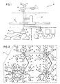
- Fig. 2 illustrates schematically that a number of subnetworks 12 in an LAN 10 may be interconnected by coaxial bus 22.
- Each subnetwork 12 has a concentrator 20 to which are connected a number of NIUs 16, each of which may have connected to it a number of devices 14.
- An NIU 16 and SIU 18 may be connected into the circuitry of a device.
- Fig. 3 is a schematic diagram of the circuitry of concentrator 20 and SIU 18 and the interconnections among NIU 16, SIU 18, concentrator 20, and bus 22.
- a transmitted packet moves from NIU 16 to SIU 18 via line 26, then to concentrator 20 via line 28 (a twisted pair identical to lines 28a, 28b which carry transmitted packets from other SIUs 18, not shown).
- the transmitted packet goes either to an addressee device outside subnetwork 12 via bus 22 (connected to concentrator 20 at connection 24) orto an addressee device 14within subnetwork 12 via, e.g., line 30 (a twisted pair identical to lines 30a, 30b, which connect to other SIUs 18).
- Line 30 also carries collision signals to SIU 18, which sends them and received packets to NIU 16 via, respectively, collision line 32 and receive line 34.
- Line 36 carries power.
- a transmitted packet from NIU 16 propagates to impedance matching buffer 40, to predistortion circuit 42 (for improvement of waveform integrity), then through line driver 44, transformer 46, and line 28 to transformer 70 within concentrator 20.
- the packet On its way between impedance matching buffer 40 and predistortion circuit 42, the packet activates squelch 48, which is part of a subcircuit within SIU 18 that routes received packets and collision signals out of SIU 18 to NIU 16.
- Received packets or collision signals arriving at SIU 18 via line 30 first propagate through transformer 50, and then to receive buffer 52, and collision buffer 54 (both of which match impedances and improve waveform integrity), activating squelch 56, which is activated only by incoming signals of appropriate amplitude and duration, thereby filtering, among other things, crosstalk on line 30.
- squelch 56 When squelch 56 is activated by either a received packet or a collision signal, it sends a "low” voltage signal (a “low”) to gate 58 and a “high” voltage signal (a “high”) to gate 60.
- Gate 58 is enabled whenever it receives both a “low” from squelch 56 and a “low” from squelch 48 (which occurs when squelch 48 detects no transmitted packets), thereby activating receive buffer 52 and permitting propagation of received packets over line 34 to NIU 16.
- Gate 60 is enabled whenever it receives both a "high” from squelch 56 and a “high” from squelch 48 (which occurs when squelch 48 detects a transmitted packet), thereby activating collision buffer 54 and permitting propagation of collision signals over line 32 to NIU 16. This interaction among squelches 48,56 and gates 58, 60 demultiplexes received packets and collision signals incoming over line 30 onto lines 34 and 32, respectively.
- the transmitted packet propagates from transformer 70 (identical to transformers 72, 74), to buffer 76 (identical to buffers 78, 80) and activates squelch 82 (identical to 84, 86), which sends a signal (S 1 ) via line 88 to programmable logic array 94, to collision gate 150 (which is enabled, thereby allowing collision signals, if any, to pass through it to SIU 18 via line 30), and to receive buffer 170 (which closes, thereby not allowing received packets onto line 30).
- Collision gates 150, 152, 154 are identical, as are receive buffers 170, 172, 174.
- PLA 94 If PLA 94 receives no other signal from either of squelches 84, 86, it sends an enabling signal (E,) via line 96 (identical to lines 98, 99) to gate 100 (identical to gates 102, 104), which is enabled and allows the transmitted packet onto transmission bus 106, from which it propagates to standard transceiver circuitry 110, (e.g., circuitry such as that of Digital Equipment Corporation Model H-4000 Ethernet Transceiver), which has, in general, conventional circuitry (including an equalizer) to condition both transmited and received packets, to limit the length of transmitted packets, and to sense collisions on bus 22.
- Transceiver 110 broadcasts the transmitted packet throughout the LAN for pickup by its addressee device.
- a transmitted packet from SIU 18 arrives at concentrator 20 via line 28 just ahead of a transmitted packet from another SIU in the same subnetwork via, e.g., line 28a.
- the second packet propagates through transformer 72 and activates squelch 84, which sends a signal (S 2 ) over line 90 that enables collision gate 152, closes receive buffer 172 and reaches PLA 94 just after signal (S,) does.
- PLA 94 senses that signal (S I ) was absolutely first, and sends a signal (E,) via line 96 that enables gate 100 (permitting the first transmitted packet to pass to transmitter bus 106, and to transceiver 110 for broadcasting throughout the LAN).
- PLA 94 also sends a signal (C 2 ) via line 91 to demultiplexer (DMUX) 130, which sends a collision signal (generated by 10 MHz oscillator 132) via line 134 to collision gate 152, through which it passes to line 30a for transmission back to the NIU that had originated the second transmitted packet.
- This collision signal is "private"; that is, only the NIU that was the source of the second transmission receives it; whereupon the NIU withdraws the transmission.
- PLA 94 does not send a signal (E 2 ) to enable gate 102, through which the second transmitted packet would have passed had it been absolutely first.
- received packets from any source in the LAN pass through the receiver circuitry of transceiver 110, through predistortion circuit 136 and buffer 138, and onto receiver bus 140, from which they move through each of receive buffers 170, 172, 174, to lines 30, 30a, 30b, to be read by appropriate addressees.
- Collisions on bus 22 between packets from separate subnetworks cause collision signals to be sent by each concentrator in LAN 10 to all SlUs, as distinguished from the "private" signalling for collision avoidance within a subnetwork, discussed above.
- the voltage level drops below the level when only one packet is on the line.
- a subcircuit within transceiver 110 monitors said voltage level and, whenever it detects such a drop, causes a collision signal to pass to all NIUs in subnetwork 12, as follows.
- comparator 146 Whenever comparator 146 in comparing the two voltage levels thus detects a collision on the bus, it sends an enabling signal over line 147 to gate 149 (connected also by line 151 to oscillator 132), which then opens to permit a 10 MHz collision signal from oscillator 132 to pass via line 153 to each of collision gates 150, 152, 154, through which it passes via lines 30, 30a, 30b to all transmitting SIUs and NIUs, which withdraw their transmissions.
- gate 135 in the receiver circuit is connected to DC voltage averaging circuit 144 and is disabled when it detects a drop in voltage on bus 22, thus preventing received packets from passing from transceiver 110 to predistortion circuit 136.
- the circuitry of concentrator 20 provides both for "local" collision avoidance within its own subnetwork 12 and for collision detection operation between two or more subnetworks 12 interconnected over coaxial bus 22.
- This local collision avoidance circuitry allows the transmitted packet that was absolutely the first to reach concentrator 20, to continue, while sending private collision signals to all other NIUs 16 in subnetwork 12 that had attempted transmissions. No collisions, therefore, can occur within subnetwork 12, thereby increasing efficiency because one of two or more "simultaneous" transmissions always will be permitted to continue.
- a general collision signal is sent by concentrators 110 to all transmitting NIUs 16 in their respective subnetworks 12, causing all attempted transmissions to be withdrawn.
- devices 14 that most often are to communicate with each other are grouped together around a single concentrator 20 so that their intercommunications may be handled through local collision avoidance circuitry, thus reducing the need for transmissions on bus 22 between subnetworks 12 and reducing, thereby, the probabilities of collisions on bus 22.
- the grouping of frequently intercommunicating devices around a common concentrator 20 permits the total of the lengths of the buses between subnetworks to be reduced because the bus does not have to be long enough to accommodate direct connections with each device 14 in the LAN.
Claims (13)
Priority Applications (1)
| Application Number | Priority Date | Filing Date | Title |
|---|---|---|---|
| AT85302828T ATE58811T1 (de) | 1984-04-23 | 1985-04-23 | Datenuebertragungsnetz. |
Applications Claiming Priority (2)
| Application Number | Priority Date | Filing Date | Title |
|---|---|---|---|
| US06/603,174 US4602364A (en) | 1984-04-23 | 1984-04-23 | Local area data communication network |
| US603174 | 1984-04-23 |
Publications (2)
| Publication Number | Publication Date |
|---|---|
| EP0161836A1 EP0161836A1 (fr) | 1985-11-21 |
| EP0161836B1 true EP0161836B1 (fr) | 1990-11-28 |
Family
ID=24414379
Family Applications (1)
| Application Number | Title | Priority Date | Filing Date |
|---|---|---|---|
| EP85302828A Expired - Lifetime EP0161836B1 (fr) | 1984-04-23 | 1985-04-23 | Réseau de communication de données |
Country Status (6)
| Country | Link |
|---|---|
| US (1) | US4602364A (fr) |
| EP (1) | EP0161836B1 (fr) |
| JP (1) | JPS60235553A (fr) |
| AT (1) | ATE58811T1 (fr) |
| CA (1) | CA1226051A (fr) |
| DE (1) | DE3580700D1 (fr) |
Families Citing this family (23)
| Publication number | Priority date | Publication date | Assignee | Title |
|---|---|---|---|---|
| AU591057B2 (en) * | 1984-06-01 | 1989-11-30 | Digital Equipment Corporation | Local area network for digital data processing system |
| US4745596A (en) * | 1985-07-16 | 1988-05-17 | Honda Giken Kogyo Kabushiki Kaisha | Multiplex communication system |
| US4831620A (en) * | 1986-07-28 | 1989-05-16 | Bull Hn Information Systems Inc. | Controller for controlling multiple LAN types |
| US4744076A (en) * | 1986-08-06 | 1988-05-10 | E. I. Du Pont De Nemours And Company | Bus structure having constant electrical characteristics |
| US4926495A (en) * | 1986-12-11 | 1990-05-15 | Motorola, Inc. | Computer aided dispatch system |
| US4858228A (en) * | 1987-02-16 | 1989-08-15 | Ricoh Company, Ltd. | Communication system employing multi-conjunction architecture |
| JPH0191556A (ja) * | 1987-03-20 | 1989-04-11 | Ricoh Co Ltd | 不定形通信網のノ−ド装置 |
| US4876742A (en) * | 1987-03-23 | 1989-10-24 | Gary Vacon | Apparatus and method for providing a wireless link between two local area network systems |
| JPS63276940A (ja) * | 1987-03-26 | 1988-11-15 | Ricoh Co Ltd | 不定形通信網のノ−ド装置 |
| US4890102A (en) * | 1987-05-26 | 1989-12-26 | Cabletron, Inc. | Visual display for communication network monitoring and troubleshooting |
| EP0303407B1 (fr) * | 1987-08-13 | 1995-01-18 | Hewlett-Packard Company | Réduction de diaphonie dans des lignes à paires torsadées non blindées |
| US4875205A (en) * | 1987-08-13 | 1989-10-17 | Hewlett-Packard Company | Crosstalk reduction in unshielded twisted-pair lines |
| US4908530A (en) * | 1987-08-13 | 1990-03-13 | Hewlett-Packard Company | Non-linear squelch circuit for IEEE-802. 3 protocol |
| US4965795A (en) * | 1988-05-10 | 1990-10-23 | Harris Corporation | D channel monitor |
| US4910729A (en) * | 1988-05-10 | 1990-03-20 | Harris Corporation | ISDN traffic generator adapter |
| FR2670925B1 (fr) * | 1990-12-20 | 1995-01-27 | Bull Sa | Architecture informatique distribuee utilisant un reseau local de type csma/cd. |
| US5285449A (en) * | 1991-04-03 | 1994-02-08 | International Business Machines Corporation | Protocol for hybrid local area networks |
| US5267237A (en) * | 1992-07-07 | 1993-11-30 | Digital Equipment Corporation | Collison detection and signaling circuit |
| US5513370A (en) * | 1992-12-22 | 1996-04-30 | National Semiconductor Corporation | Twisted pair and attachment unit interface (AUI) coding and transceiving circuit with full duplex, testing, isolation, and automatic output selection |
| US5446914A (en) * | 1992-12-22 | 1995-08-29 | National Semiconductor Corporation | Twisted pair and attachment unit interface (AUI) coding and transceiving circuit with full duplex, testing, and isolation modes |
| US6343071B1 (en) * | 1995-01-11 | 2002-01-29 | Simtek Corporation | Wireless desktop area network system |
| WO1999053627A1 (fr) | 1998-04-10 | 1999-10-21 | Chrimar Systems, Inc. Doing Business As Cms Technologies | Systeme de communication avec un equipement electronique sur un reseau |
| EP3516406B1 (fr) | 2016-09-28 | 2020-07-22 | CommScope, Inc. of North Carolina | Prise, compteur et dispositif de transformation permettant la distribution d'énergie à partir d'une installation hfc |
Family Cites Families (15)
| Publication number | Priority date | Publication date | Assignee | Title |
|---|---|---|---|---|
| US4063220A (en) * | 1975-03-31 | 1977-12-13 | Xerox Corporation | Multipoint data communication system with collision detection |
| US4099024A (en) * | 1977-02-16 | 1978-07-04 | Xerox Corporation | Communications network repeater |
| US4332022A (en) * | 1978-03-27 | 1982-05-25 | Discovision Associates | Tracking system and method for video disc player |
| US4210780A (en) * | 1978-03-27 | 1980-07-01 | The Mitre Corporation | Multiple access digital communications system |
| US4281380A (en) * | 1978-12-27 | 1981-07-28 | Harris Corporation | Bus collision avoidance system for distributed network data processing communications system |
| US4234952A (en) * | 1979-06-07 | 1980-11-18 | Ford Motor Company | Conflict resolution by retransmission delay on shared communication medium |
| US4292623A (en) * | 1979-06-29 | 1981-09-29 | International Business Machines Corporation | Port logic for a communication bus system |
| US4347498A (en) * | 1979-11-21 | 1982-08-31 | International Business Machines Corporation | Method and means for demand accessing and broadcast transmission among ports in a distributed star network |
| US4432088A (en) * | 1981-04-30 | 1984-02-14 | The United States Of America As Represented By The United States Department Of Energy | Carrier sense data highway system |
| US4412326A (en) * | 1981-10-23 | 1983-10-25 | Bell Telephone Laboratories, Inc. | Collision avoiding system, apparatus and protocol for a multiple access digital communications system including variable length packets |
| US4531238A (en) * | 1981-12-03 | 1985-07-23 | Xerox Corporation | Statistical contention control for star configured communication networks |
| US4413258A (en) * | 1981-12-14 | 1983-11-01 | Burroughs Corporation | Interconnection for local area contention networks |
| US4472712A (en) * | 1982-03-05 | 1984-09-18 | At&T Bell Laboratories | Multipoint data communication system with local arbitration |
| US4464658A (en) * | 1982-03-05 | 1984-08-07 | At&T Laboratories | Multipoint data communication system with collision detection |
| US4481626A (en) * | 1982-05-05 | 1984-11-06 | Xerox Corporation | Transceiver multiplexor |
-
1984
- 1984-04-23 US US06/603,174 patent/US4602364A/en not_active Expired - Fee Related
-
1985
- 1985-04-18 CA CA000479433A patent/CA1226051A/fr not_active Expired
- 1985-04-23 DE DE8585302828T patent/DE3580700D1/de not_active Expired - Lifetime
- 1985-04-23 JP JP60087344A patent/JPS60235553A/ja active Pending
- 1985-04-23 AT AT85302828T patent/ATE58811T1/de not_active IP Right Cessation
- 1985-04-23 EP EP85302828A patent/EP0161836B1/fr not_active Expired - Lifetime
Also Published As
| Publication number | Publication date |
|---|---|
| US4602364A (en) | 1986-07-22 |
| ATE58811T1 (de) | 1990-12-15 |
| EP0161836A1 (fr) | 1985-11-21 |
| CA1226051A (fr) | 1987-08-25 |
| JPS60235553A (ja) | 1985-11-22 |
| DE3580700D1 (de) | 1991-01-10 |
Similar Documents
| Publication | Publication Date | Title |
|---|---|---|
| EP0161836B1 (fr) | Réseau de communication de données | |
| EP0029502B1 (fr) | Procédé de transmission de données entre les portes d'un système de communication comprenant un réseau de noeuds interconnectés et un système de communication comprenant un réseau de noeuds interconnectés et une unité de noeud pour l'utilisation dans un procédé ou système comme mentionné ci-dessus | |
| AU600577B2 (en) | Lan communication system and medium adapter for use therewith | |
| US4918688A (en) | Method and apparatus for coupling computer work stations | |
| US5414708A (en) | Method and apparatus for connecting nodes for a computer network | |
| US5577023A (en) | Method and apparatus for automatic configuration of a network connection | |
| EP0224132B1 (fr) | Emetteur-récepteur optique composite | |
| EP0093623A2 (fr) | Multiplexeur pour émetteur-récepteur | |
| US5598414A (en) | Access to transmit on a message priority basis | |
| JPS5899046A (ja) | 星形通信網 | |
| US5796738A (en) | Multiport repeater with collision detection and jam signal generation | |
| EP0074672B1 (fr) | Système asynchrone de bus de données | |
| US6487214B1 (en) | Method and apparatus for implementing an ethernet protocol using three wires | |
| US4658396A (en) | Redundancy arrangement for a local area network | |
| US5608729A (en) | Method and apparatus for providing two-way data communication cover a widely distributed network | |
| US4935926A (en) | Networking circuitry | |
| US4887259A (en) | Communication network having multi-conjunction architecture | |
| US5119398A (en) | Signal regenerator for two-wire local area network | |
| EP0899915B1 (fr) | Dispositif et procédé pour l' alimentation sélective de paquets de données entre domaines de media dans un répétiteur de réseau | |
| US4882728A (en) | Networking circuitry | |
| US6111890A (en) | Gigabuffer lite repeater scheme | |
| GB2265797A (en) | Communication system including twisted pair and coaxial cable networks | |
| EP0170476A2 (fr) | Système de communication de données | |
| US4815070A (en) | Node apparatus for communication network having multi-conjunction architecture | |
| US4943979A (en) | Local access network signal regnerator |
Legal Events
| Date | Code | Title | Description |
|---|---|---|---|
| PUAI | Public reference made under article 153(3) epc to a published international application that has entered the european phase |
Free format text: ORIGINAL CODE: 0009012 |
|
| AK | Designated contracting states |
Designated state(s): AT BE CH DE FR GB IT LI LU NL SE |
|
| 17P | Request for examination filed |
Effective date: 19860306 |
|
| 17Q | First examination report despatched |
Effective date: 19871113 |
|
| GRAA | (expected) grant |
Free format text: ORIGINAL CODE: 0009210 |
|
| AK | Designated contracting states |
Kind code of ref document: B1 Designated state(s): AT BE CH DE FR GB IT LI LU NL SE |
|
| PG25 | Lapsed in a contracting state [announced via postgrant information from national office to epo] |
Ref country code: SE Effective date: 19901128 Ref country code: NL Effective date: 19901128 Ref country code: LI Effective date: 19901128 Ref country code: IT Free format text: LAPSE BECAUSE OF FAILURE TO SUBMIT A TRANSLATION OF THE DESCRIPTION OR TO PAY THE FEE WITHIN THE PRESCRIBED TIME-LIMIT;WARNING: LAPSES OF ITALIAN PATENTS WITH EFFECTIVE DATE BEFORE 2007 MAY HAVE OCCURRED AT ANY TIME BEFORE 2007. THE CORRECT EFFECTIVE DATE MAY BE DIFFERENT FROM THE ONE RECORDED. Effective date: 19901128 Ref country code: FR Effective date: 19901128 Ref country code: CH Effective date: 19901128 Ref country code: BE Effective date: 19901128 Ref country code: AT Effective date: 19901128 |
|
| REF | Corresponds to: |
Ref document number: 58811 Country of ref document: AT Date of ref document: 19901215 Kind code of ref document: T |
|
| REF | Corresponds to: |
Ref document number: 3580700 Country of ref document: DE Date of ref document: 19910110 |
|
| REG | Reference to a national code |
Ref country code: CH Ref legal event code: PL |
|
| NLV1 | Nl: lapsed or annulled due to failure to fulfill the requirements of art. 29p and 29m of the patents act | ||
| EN | Fr: translation not filed | ||
| PG25 | Lapsed in a contracting state [announced via postgrant information from national office to epo] |
Ref country code: GB Effective date: 19910423 |
|
| PG25 | Lapsed in a contracting state [announced via postgrant information from national office to epo] |
Ref country code: LU Free format text: LAPSE BECAUSE OF NON-PAYMENT OF DUE FEES Effective date: 19910430 |
|
| PLBE | No opposition filed within time limit |
Free format text: ORIGINAL CODE: 0009261 |
|
| STAA | Information on the status of an ep patent application or granted ep patent |
Free format text: STATUS: NO OPPOSITION FILED WITHIN TIME LIMIT |
|
| 26N | No opposition filed | ||
| GBPC | Gb: european patent ceased through non-payment of renewal fee | ||
| PGFP | Annual fee paid to national office [announced via postgrant information from national office to epo] |
Ref country code: DE Payment date: 19920831 Year of fee payment: 8 |
|
| PG25 | Lapsed in a contracting state [announced via postgrant information from national office to epo] |
Ref country code: DE Effective date: 19940101 |
|
| P01 | Opt-out of the competence of the unified patent court (upc) registered |
Effective date: 20230520 |