EP0160300A2 - Method and circuit arrangement for establishing connections and transmitting communication signals between subscriber's stations or line groups in a communications exchange, in particular a data exchange, having a loop arrangement - Google Patents
Method and circuit arrangement for establishing connections and transmitting communication signals between subscriber's stations or line groups in a communications exchange, in particular a data exchange, having a loop arrangement Download PDFInfo
- Publication number
- EP0160300A2 EP0160300A2 EP85105283A EP85105283A EP0160300A2 EP 0160300 A2 EP0160300 A2 EP 0160300A2 EP 85105283 A EP85105283 A EP 85105283A EP 85105283 A EP85105283 A EP 85105283A EP 0160300 A2 EP0160300 A2 EP 0160300A2
- Authority
- EP
- European Patent Office
- Prior art keywords
- connection
- line
- line connection
- computers
- subscriber stations
- Prior art date
- Legal status (The legal status is an assumption and is not a legal conclusion. Google has not performed a legal analysis and makes no representation as to the accuracy of the status listed.)
- Granted
Links
Images


Classifications
-
- H—ELECTRICITY
- H04—ELECTRIC COMMUNICATION TECHNIQUE
- H04L—TRANSMISSION OF DIGITAL INFORMATION, e.g. TELEGRAPHIC COMMUNICATION
- H04L12/00—Data switching networks
- H04L12/28—Data switching networks characterised by path configuration, e.g. LAN [Local Area Networks] or WAN [Wide Area Networks]
- H04L12/42—Loop networks
- H04L12/437—Ring fault isolation or reconfiguration
-
- H—ELECTRICITY
- H04—ELECTRIC COMMUNICATION TECHNIQUE
- H04L—TRANSMISSION OF DIGITAL INFORMATION, e.g. TELEGRAPHIC COMMUNICATION
- H04L12/00—Data switching networks
- H04L12/50—Circuit switching systems, i.e. systems in which the path is physically permanent during the communication
-
- H—ELECTRICITY
- H04—ELECTRIC COMMUNICATION TECHNIQUE
- H04L—TRANSMISSION OF DIGITAL INFORMATION, e.g. TELEGRAPHIC COMMUNICATION
- H04L12/00—Data switching networks
- H04L12/54—Store-and-forward switching systems
- H04L12/56—Packet switching systems
Definitions
- the invention relates to a method for establishing connections and transmitting message signals between different subscriber stations or between line connection groups of a telecommunication switching system, each comprising a plurality of subscriber stations, in particular a data switching system, in which the relevant subscriber stations or line connection groups are located in a ring line arrangement in which computers are also included, via which at least the connection traffic between the relevant subscriber stations or line connection groups is processed.
- a switching system is already known (US Pat. No. 4,032,899), in which a plurality of line connection modules and a plurality of switching processor modules are connected to a bus line arrangement.
- Each line connection module has a group of transmission lines.
- the switching processor modules are each permanently assigned to a line connection module or a group of transmission lines.
- Each switching processor module contains tables in which predefined assignments between each switching processor module and the associated group of transmission lines are stored.
- routing information is stored in each switching processor module, which designates those switching processor modules that all other transmission lines are associated. Connections between two transmission lines belonging to different line connection modules are established in the following way: First, a connection is established from the transmission line carrying a call signal to the associated switching processor module.
- the relevant switching processor module emits a request signal to the switching processor module to which the subscriber station or transmission line to be called, which is designated by the relevant information, is associated.
- the relevant request signal it is checked whether the desired transmission line or subscriber station is ready for signal reception. If this is the case, a separate request signal is emitted from the switching processor module viewed last to the switching processor module viewed first.
- the switching processor module - to which a connection has already been established on the basis of the call signal - establishes the connection to the line connection module in question.
- the switching processor module that was included in the check is no longer included in the connection setup in question. However, this means that if a malfunction occurs in the switching processor module that practically controls the connection establishment, the connection establishment can be very easily disturbed.
- Ring line systems are also known (US Pat. No. 2,986,602, "IBM Technical Disclosure Bulletin", Vol. 7, No. 7, Dec. 1964, pages 592, 593), in which connections between two subscriber stations or between two groups of Subscriber stations can only be set up via a central office (computer). However, this is also not ensures the desired security when establishing a connection.
- the invention is therefore based on the object of showing a way in which a particularly secure connection and secure transmission of signals between different subscriber stations or line connection groups is possible with a method of the type mentioned.
- the object outlined above is achieved according to the invention in a method of the type mentioned at the outset by establishing the connection between two subscriber stations or between two line connection groups via two of the computers mentioned, which, like the subscriber stations or line connection groups concerned, are connected to the ring line arrangement and by to which one computer operates the subscriber station or line connection group that is calling, while the other computer operates the called subscriber station or line connection group, and that information about those subscriber stations or line connection groups between which a connection is currently being made is available in each of the computers concerned is.
- the invention has the advantage that a secure connection setup and secure signal transmission between the subscriber stations or line connection groups to be included in a connection is possible in a relatively simple manner. If one of the two computers used in the respective connection establishment fails, the connection in question can still be established by the still intact computer. At this point it should be noted that the so-called call confirmation signal is transmitted via the same route is used to establish the connection between two subscriber stations or line connection groups.
- the transmission of control signals relating to the establishment of a connection and the transmission of message signals between the subscriber stations or line connection groups involved in a connection establishment or connection and computers via the ring line arrangement is expedient only after the relevant ring line arrangement has been separately released for the respective subscriber station or line connection group or the respective computer. This results in the advantage of secure operation both when establishing a connection and when transmitting message signals via the ring line arrangement.
- the separate release of the ring line arrangement can take place by using line access methods as are known in connection with the ring line systems relating to the prior art cited at the beginning.
- a circuit arrangement is preferably used to carry out the method according to the invention, which is characterized in that two computers in the ring line arrangement are included in each connection setup between two subscriber stations or line connection groups are, one of which is assigned to the calling subscriber station or line connection group and the other of which is assigned to the respectively called subscriber station or line connection group, and that each of the computers in question contains information about those subscriber stations or line connection groups between which a connection is currently being set up .
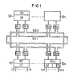
- FIG. 1 shows the overall structure of a circuit arrangement according to the invention in a block diagram.
- the circuit arrangement in question has a plurality of line connection groups TG1 to TGm, to each of which a plurality of subscriber stations or transmission lines Lll ... Llx or Lml ... Lmx are connected.
- the transmission lines shown in FIG. 1 are bidirectionally operated transmission lines, via which signals are thus transmitted in both transmission directions.
- Each line connection group TG1 to TGm also includes a so-called line group controller BC1 to BCm, which controls the transmission of the various signals that occur.
- Separate interface devices also belong to the line connection groups TG1 to TGm shown in FIG.
- the interface devices belonging to the line connection group TG1 are designated BIal and BIbl.
- the interface devices belonging to the line connection group TGm are designated BIam and BIbm.
- the individual line connections are located with these interface devices Groups TG1 to TGM in a ring line arrangement, which in particular allows only one direction of transmission to transmit signals, in the present case it contains two separate ring bus lines, one of which is designated BUS 0 and the other of which is designated BUS 1, and which in each case is also in particular only in one Direction of transmission of signals.
- the ring line arrangement also contains further interface devices which belong to computers SB1 to SBn, which serve as switching units.
- the computer or the switching unit SB1 is inserted into the two ring bus lines via interface devices BIcl and BIdl.
- the computer or the switching unit SBn is inserted into the relevant ring bus lines with interface devices BIcn, BIdn.
- Each computer or each switching unit SB1 to SBn has a central unit and a central unit control unit connected to it, which together with the associated central unit is to be regarded as the actual switching processor of the respective computer or the respective switching unit.
- Such a switching processor SPU is indicated in FIG. 1 in connection with the computer or the switching unit SB1.
- Each computer or switching unit also has a bus coupler or a switching processor controller, which is referred to as SPC with respect to the computer or switching unit SB1.
- each of these ring bus lines has a plurality of individual lines, for example 16 individual lines, via which signals are transmitted in parallel.
- the two ring bus lines only one ring bus line is normally used in operation; the other ring bus line is available as a reserve ring bus line if one of the ring bus lines fails as a result of an error.
- each line connection group TG1 to TGm is assigned one of the computers or one of the switching units SB1 to SBn.
- both the individual line connection groups and the individual switching units contain memories in which the relevant assignments are recorded.
- the address of the switching unit SB1 can be stored in the corresponding memory of the line connection group TG1 as that switching unit which is assigned to the relevant line connection group TG1.
- the address of the line connection group TG1 can be stored in the memory of the switching unit SB1 with respect to the transmission lines L11 to Llx connected to the line connection group TG1.
- information is stored in the memories of the switching units or computers SB1 to SBn as to which computer or which switching unit is responsible for the respective other transmission lines or line connection groups is associated. This means that basically each of the computers or each of the switching units SB1 to SBn serves a line connection group of the line connection groups TG1 to TGm and also has information about corresponding affiliations with respect to each of the other computers.
- each of the computers or each of the switching units SB1 to SBn can be assigned to one of the other computers or one of the other switching units as a reserve unit in order to take over their tasks in the event of failure of the first-mentioned computer or the first-mentioned switching unit.
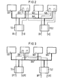
- FIG. 2 illustrates in a block diagram the processes that take place when a connection is established between two line connection groups.
- four computers or switching units SB1, SB2, SB3, SB4 and two line connection groups TG1 and TG2 are provided, which are connected together to a ring bus line BUS, which is only indicated schematically.
- the line connection group TG1 is associated with the computer or the switching unit SB2 and that the line connection group TG2 is associated with the computer or the switching unit SB4.
- the call confirmation signal CC which is supplied to the line connection group TG2 via one of its transmission lines - possibly via the same transmission line via which the call request signal CR was previously transmitted - is transmitted from the line connection group TG2 via the computer SB4, then via the computer SB2 and finally via the Line connection group TG1 forwarded.
- FIG. 3 illustrates the message signal transmission phase in the arrangement shown in FIG. 2.
- data or, more generally, message signals ie text, image, voice and other signals
- the message signals can occur in particular as data packets, specifically as data packets DPI in the direction from the line connection group TG1 to the line connection group TG2 and as data packets DP2 in the reverse direction of transmission.
- FIG. 4 is a block diagram of those when a connection between two line connection groups is triggered processes are illustrated.
- the computer or the switching unit SB4 had assumed the switching function with regard to the two line connection groups TG1 and TG2.
- the assignment between the computer or switching unit and the line connection group is, however, also the same here as was explained in connection with FIG. 2.
- a trigger request signal RR is fed to the line connection group TG2 via a transmission line.
- This trigger request signal RR reaches the computer or the switching unit SB4, which then sends a trigger confirmation signal RAC1 back to the relevant line connection group TG2.
- the line connection group TG2 in question forwards this triggering confirmation signal RAC1 via the transmission line in question.
- the computer or the switching unit SB4 forwards the trigger request signal RR, which he or she has previously received, or a signal corresponding to this signal to the computer or the switching unit SB2.
- This computer or this switching unit SB2 belongs to the line connection group that was included in the connection that is now to be triggered. The relevant assignment is - as already explained above - recorded in a memory of the computer or the switching unit SB4.
- the aforementioned trigger request signal RR finally arrives from the computer or the switching unit SB2 via the associated line connection group TG1 and from this via the transmission line in question.
- the line connection group TG1 is connected via this last-mentioned transmission line or any other transmission line finally a trigger confirmation signal RAC2 is supplied, which is finally transmitted to the computer or the switching unit SB2.
- FIG. 5 illustrates processes which take place when the computer involved in a connection or the connection unit involved in the connection in question fails as a result of a fault.
- FIG. 5 shows the same structure as that shown in FIGS. 2 and 3.
- the computer or the switching unit SB4 is included in the connection between the two line connection groups TG1 and TG2 after the computer or the switching unit SB2 has failed as a result of a fault.
- the computer or the switching unit SB4 serves as a connection-specific reserve unit in relation to the computer or the switching unit SB2 for the connection (s) that is set up, in which information about all connections is contained in which the computer or the switching unit SB2 is to be included.
- the related 5 constellation assumed to transmit the message signals, in particular in the form of data signal packets DP1 and DP2, between the two line connection groups TG1 and TG2 via the computer or the switching unit SB4.
- connection establishment In connection with the relationships explained in FIGS. 2 to 5, the connection establishment, the message signal transmission and the connection disconnection in the circuit arrangement according to the invention have been considered.
- the transmission of the individual signals takes place on the ring bus line BUS in operation.
- various transmission methods can be used, as are known from the prior art relating to ring line systems considered at the outset.
- the signal transmissions can also take place in the course of so-called virtual connections, in which the address of the target device to be controlled is associated with the respectively transmitted signal block or signal packet. This address is then recognized by the relevant target device, whereupon the signals transmitted together with the relevant address are received by the relevant device.
- the transmission of such signal packets via the ring line arrangement can take place upon separate release of the device in question, for which purpose a separate release signal present in the ring line arrangement can be used, which is passed on from device to device when signal transmission has been completed.
- FIG. 6 shows a section of the possible structure of one of the computers or one of the switching units and one of the associated interface devices associated therewith illustrated.
- the computer SB1 indicated in FIG. 6 has in its area SPU which forms the actual switching processor a microprocessor MP1 which is connected to an internal bus line arrangement IB1 which comprises an address bus, a data bus and a control bus.
- a program memory ROM1, a data memory RAM1 and an interface module Intl are also connected to this bus line arrangement, which connects the relevant internal bus line arrangement IB1 to a further internal bus line arrangement which is connected to a switching processor corresponding to the switching processor SPU under consideration.
- a further interface module Int2 is also connected to the internal bus line arrangement IB1 and is connected to yet another interface module Int3 of the switching processor controller SPC of the computer SBI shown.
- the relevant switching processor controller SPC has its own microprocessor MP2, which is connected to an internal bus line arrangement IB2, which also has an address bus, a data bus and a control bus.
- the last-mentioned interface module Int3 and a read-only memory ROM2 containing programs required for the operation of the microprocessor MP2 are connected to this internal bus line arrangement IB2.
- the internal bus line arrangement IB2 is connected to yet another interface module Int4, which connects the relevant bus line arrangement IB2 to a corresponding bus line arrangement which belongs to a further switching processor control of the computer SB1 under consideration.
- the interface device BIcl shown in FIG. 6, shown below, is connected to the internal bus line arrangement IB2.
- This interface device comprises two interface modules Int5 and Int6, which are connected to the mentioned internal bus line arrangement IB2 and which in the rest are connected to the ring bus line 1 shown in FIG.
- the interface device BIcl also includes a read / write memory RAM2, which is also connected to the internal bus line arrangement IB2.
- This memory RAM2 serves for the temporary storage of data signals . which are fed to it from one of the two interface modules Int5, Int6 or from the interface module Int3.
- the internal bus line arrangements IB1 and IB2 are connected via separate interface modules Intl and Int4 to further internal bus line arrangements, which belong to the devices of the computer or the switching unit SB1 corresponding to the devices SPU or SPC.
- the interface device BIdl which is still indicated in FIG. 6 and belongs to the ring bus line BUS 0, belongs to these further devices.
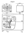
- FIG. 7 illustrates the possible structure of one of the line connection groups present in the circuit arrangement according to the invention, namely the line connection group TG1 together with its associated interface devices BIal, BIbl.
- the interface device BIal includes a read / write memory RAM3, which is used for the temporary storage of data signals supplied to it.
- the memory RAM3 and the two interface modules Int7, Int8 are connected together to an internal bus line arrangement IB3, which comprises an address bus, a data bus and a control bus.
- This internal bus line arrangement IB3 leads to the line connection group TG1, specifically to the associated line group controller BC1.
- a microprocessor MP3 is contained in this line group control, which is connected to the internal bus line arrangement IB3 together with a read-only memory ROM3 containing programs required for operation.
- An interface module Int9 is also connected to this internal bus line arrangement IB3, which connects the internal bus line arrangement IB3 to a corresponding bus line arrangement, which is connected to the devices corresponding to the previously explained devices and to the interface device BIbl, which is located in the ring bus line BUS 0.
- the internal bus line IB3 is connected via a still further interface module Int10 with still another internal bus line IB4, which belongs to a 'line of the connection means of the line terminal unit LT1.
- a further microprocessor MP4 a read-only memory ROM4 containing the programs required for operating this microprocessor, a data memory ROM4 and a further interface module Intll are connected to the relevant internal bus line arrangement IB4.
- the transmission line Lll is connected to this interface module Intll.
- the other transmission lines belonging to the line connection group under consideration are connected to the internal bus line arrangement IB4 via the interface module Intll.
- the internal bus line arrangement IB4 is also connected via an interface module corresponding to the interface module Int10 to the bus line arrangement which is via the one already mentioned Interface module Int9 is connected to the internal bus line arrangement IB3.
- FIGS. 6 and 7 Possible embodiments for the devices explained in connection with FIG. 1 have been described above with reference to FIGS. 6 and 7.
- the microprocessors, memories and interface modules mentioned in this connection can be customary modules of microprocessor systems.
- the internal bus lines shown in FIGS. 6 and 7 each have a plurality of buses containing individual lines, each of which is indicated by a single line with a short dash.
- the procedure may be such that the respectively disturbed computer or the respectively disturbed switching unit informs the associated line connection group of the presence of the fault condition, whereupon the assignment of the line connection group in question to one or more specified other computers or switching units is changed.
- different reserve computers or switching units are used for a computer or a switching unit, depending on whether the computer or switching unit in question and the computer in question as connection-specific computer are already included in a connection are or not.
Abstract
Description
Die Erfindung bezieht sich auf ein Verfahren zum Herstellen von Verbindungen und Ubertragen von Nachrichtensignalen zwischen verschiedenen Teilnehmerstellen bzw. zwischen jeweils eine Mehrzahl von Teilnehmerstellen umfassenden Leitungsanschlußgruppen einer Fernmeldevermittlungsanlage, insbesondere einer Datenvermittlungsanlage, in der die betreffenden Teilnehmerstellen bzw. Leitungsanschlußgruppen in einer Ringleitungsanordnung liegen, in welcher außerdem Rechner enthalten sind, über die zumindest der Verbindungsverkehr zwischen den betreffenden Teilnehmerstellen bzw. Leitungsanschlußgruppen abgewickelt wird.The invention relates to a method for establishing connections and transmitting message signals between different subscriber stations or between line connection groups of a telecommunication switching system, each comprising a plurality of subscriber stations, in particular a data switching system, in which the relevant subscriber stations or line connection groups are located in a ring line arrangement in which computers are also included, via which at least the connection traffic between the relevant subscriber stations or line connection groups is processed.
Es ist bereits ein Vermittlungssystem bekannt (US-PS 40 32 899), bei dem an einer Busleitungsanordnung eine Mehrzahl von Leitungsanschlußmoduln und eine Mehrzahl von Vermittlungsprozessormoduln angeschlossen sind. Jeder Leitungsanschlußmodul weist eine Gruppe von Übertragungsleitungen auf. Die Vermittlungsprozessormoduln sind jeweils einem Leitungsanschlußmodul bzw. einer Gruppe von Ubertragungsleitungen fest zugeordnet. In jedem Vermittlungsprozessormodul sind Tabellen enthalten, in denen vorgegebene Zuordnungen zwischen je einem Vermittlungsprozessormodul und der zugehörigen Gruppe von Ubertragungsleitungen gespeichert sind. Außerdem sind in jedem Vermittlungsprozessormodul Leitweginformationen gespeichert, welche diejenigen Vermittlungsprozessormoduln bezeichnen, die allen übrigen Ubertragungsleitungen zugehörig sind. Der Aufbau von Verbindungen zwischen zwei übertragungsleitungen, die zu unterschiedlichen Leitungsanschlußmoduln gehören, erfolgt in folgender Weise: Zunächst wird eine Verbindung von der ein Rufsignal führenden Übertragungsleitung zu dem zugehörigen Vermittlungsprozessormodul hin aufgebaut. Anhand der Rufinformation gibt der betreffende Vermittlungsprozessormodul ein Anforderungssignal an denjenigen Vermittlungsprozessormodul ab, dem die durch die betreffende Information bezeichnete anzurufende Teilnehmerstelle bzw. Ubertragungsleitung zugehörig ist. Anhand des betreffenden Anforderungssignals wird überprüft, ob die gewünschte Übertragungsleitung bzw. Teilnehmerstelle zur Signalaufnahme bereit ist. Ist dies der Fall, wird von dem zuletzt betrachteten Vermittlungsprozessormodul an den zuerst betrachteten Vermittlungsprozessormodul ein gesondertes Aufforderungssignal abgegeben. Auf die Aufnahme dieses Aufforderungssignals hin baut der Vermittlungsprozessormodul - zu dem aufgrund des Rufsignals bereits eine Verbindung aufgebaut ist - die Verbindung zu dem in Frage kommenden Leitungsanschlußmodul auf. Der Vermittlungsprozessormodul, der in die Überprüfung einbezogen war, ist in den betreffenden Verbindungsaufbau nicht mehr einbezogen. Dies bedeutet aber, daß bei Auftreten einer Störung in demjenigen Vermittlungsprozessormodul, der praktisch den Verbindungsaufbau steuert, die Durchführung des Verbindungsaufbaus sehr leicht gestört sein kann.A switching system is already known (US Pat. No. 4,032,899), in which a plurality of line connection modules and a plurality of switching processor modules are connected to a bus line arrangement. Each line connection module has a group of transmission lines. The switching processor modules are each permanently assigned to a line connection module or a group of transmission lines. Each switching processor module contains tables in which predefined assignments between each switching processor module and the associated group of transmission lines are stored. In addition, routing information is stored in each switching processor module, which designates those switching processor modules that all other transmission lines are associated. Connections between two transmission lines belonging to different line connection modules are established in the following way: First, a connection is established from the transmission line carrying a call signal to the associated switching processor module. On the basis of the call information, the relevant switching processor module emits a request signal to the switching processor module to which the subscriber station or transmission line to be called, which is designated by the relevant information, is associated. On the basis of the relevant request signal, it is checked whether the desired transmission line or subscriber station is ready for signal reception. If this is the case, a separate request signal is emitted from the switching processor module viewed last to the switching processor module viewed first. Upon receiving this request signal, the switching processor module - to which a connection has already been established on the basis of the call signal - establishes the connection to the line connection module in question. The switching processor module that was included in the check is no longer included in the connection setup in question. However, this means that if a malfunction occurs in the switching processor module that practically controls the connection establishment, the connection establishment can be very easily disturbed.
Es sind ferner Ringleitungssysteme bekannt (US-PS 29 86 602, "IBM Technical Disclosure Bulletin", Vol. 7, Nr. 7, Dez. 1964, Seiten 592, 593), bei denen Verbindungen zwischen zwei Teilnehmerstellen bzw. zwischen zwei Gruppen von Teilnehmerstellen über lediglich eine Zentrale (Rechner) aufgebaut werden können. Damit ist jedoch ebenfalls nicht die gewünschte Sicherheit beim Verbindungsaufbau gewährleistet.Ring line systems are also known (US Pat. No. 2,986,602, "IBM Technical Disclosure Bulletin", Vol. 7, No. 7, Dec. 1964, pages 592, 593), in which connections between two subscriber stations or between two groups of Subscriber stations can only be set up via a central office (computer). However, this is also not ensures the desired security when establishing a connection.
Der Erfindung liegt demgemäß die Aufgabe zugrunde, einen Weg zu zeigen, wie bei einem Verfahren der eingangs genannten Art ein besonders sicherer Verbindungsaufbau und eine sichere Übertragung von Signalen zwischen verschiedenen Teilnehmerstellen bzw. Leitungsanschlußgruppen möglich ist.The invention is therefore based on the object of showing a way in which a particularly secure connection and secure transmission of signals between different subscriber stations or line connection groups is possible with a method of the type mentioned.
Gelöst wird die vorstehend aufgezeigte Aufgabe bei einem Verfahren der eingangs genannten Art erfindungsgemäß dadurch, daß der Verbindungsaufbau zwischen zwei Teilnehmerstellen bzw. zwischen zwei Leitungsanschlußgruppen über zwei der genannten Rechner abgewickelt wird, die wie die betreffenden Teilnehmerstellen bzw. Leitungsanschlußgruppen mit der Ringleitungsanordnung verbunden sind und von denen der eine Rechner die Teilnehmerstelle bzw. Leitungsanschlußgruppe bedient, die gerade ruft, während der andere Rechner die angerufene Teilnehmerstelle bzw. Leitungsanschlußgruppe bedient, und daß in jedem der betreffenden Rechner Informationen über diejenigen Teilnehmerstellen bzw. Leitungsanschlußgruppen bereitgehalten werden, zwischen denen gerade eine Verbindung aufzubauen ist.The object outlined above is achieved according to the invention in a method of the type mentioned at the outset by establishing the connection between two subscriber stations or between two line connection groups via two of the computers mentioned, which, like the subscriber stations or line connection groups concerned, are connected to the ring line arrangement and by to which one computer operates the subscriber station or line connection group that is calling, while the other computer operates the called subscriber station or line connection group, and that information about those subscriber stations or line connection groups between which a connection is currently being made is available in each of the computers concerned is.
Die Erfindung bringt den Vorteil mit sich, daß auf relativ einfache Weise ein gesicherter Verbindungsaufbau und eine sichere Signalübertragung zwischen den jeweils in eine Verbindung einzubeziehenden Teilnehmerstellen bzw. Leitungsanschlußgruppen möglich ist. Fällt nämlich einer der bei dem jeweiligen Verbindungsaufbau benutzten beiden Rechner aus_, so kann die betreffende Verbindung dennoch von dem noch intakten Rechner aufgebaut werden. An dieser Stelle sei angemerkt, daß das sogenannte Rufbestätigungssignal über den gleichen Weg übertragen wird, über den die Verbindung zwischen zwei Teilnehmerstellen bzw. Leitungsanschlußgruppen aufgebaut worden ist.The invention has the advantage that a secure connection setup and secure signal transmission between the subscriber stations or line connection groups to be included in a connection is possible in a relatively simple manner. If one of the two computers used in the respective connection establishment fails, the connection in question can still be established by the still intact computer. At this point it should be noted that the so-called call confirmation signal is transmitted via the same route is used to establish the connection between two subscriber stations or line connection groups.
Zweckmäßigerweise wird die Übertragung von Nachrichtensignalen zwischen den jeweils in eine Verbindung einbezogenen Teilnehmerstellen bzw. Leitungsanschlußgruppen über nur einen der im Zuge des Verbindungsaufbaus berücksichtigten Rechner vorgenommen. Hierdurch ergibt sich der Vorteil, daß in der Nachrichtensignal-Ubertragungsphase eine Entlastung der in der Ringleitungsanordnung liegenden Rechner erreicht ist und daß trotzdem eine sichere Signalübertragung gewährleistet bleibt.The transmission of message signals between the subscriber stations or line connection groups involved in a connection is expediently carried out via only one of the computers taken into account in the course of establishing the connection. This has the advantage that in the message signal transmission phase a relief of the computers located in the ring line arrangement is achieved and that nevertheless secure signal transmission remains guaranteed.
Zweckmäßigerweise wird die Übertragung von den Verbindungsaufbau betreffenden Steuersignalen und die Übertragung .von Nachrichtensignalen zwischen den jeweils in einen Verbindungsaufbau bzw. in eine Verbindung einbezogenen Teilnehmerstellen bzw. Leitungsanschlußgruppen und Rechnern über die Ringleitungsanordnung erst nach gesonderter Freigabe der betreffenden Ringleitungsanordnung für die jeweilige Teilnehmerstelle bzw. Leitungsanschlußgruppe bzw. den jeweiligen Rechner vorgenommen. Hierdurch ergibt sich der Vorteil eines gesicherten Betriebs sowohl beim Verbindungsaufbau als auch bei der Übertragung von Nachrichtensignalen über die Ringleitungsanordnung. Die gesonderte Freigabe der Ringleitungsanordnung kann dabei durch Anwendung von Leitungszugriffsverfahren erfolgen, wie sie im Zusammenhang mit dem eingangs zitierten Stand der Technik betreffenden Ringleitungssysteme bekannt sind.The transmission of control signals relating to the establishment of a connection and the transmission of message signals between the subscriber stations or line connection groups involved in a connection establishment or connection and computers via the ring line arrangement is expedient only after the relevant ring line arrangement has been separately released for the respective subscriber station or line connection group or the respective computer. This results in the advantage of secure operation both when establishing a connection and when transmitting message signals via the ring line arrangement. The separate release of the ring line arrangement can take place by using line access methods as are known in connection with the ring line systems relating to the prior art cited at the beginning.
Zur Durchführung des Verfahrens gemäß der Erfindung dient vorzugsweise eine Schaltungsanordnung, die dadurch gekennzeichnet ist, daß in jeden Verbindungsaufbau zwischen zwei Teilnehmerstellen bzw. Leitungsanschlußgruppen zwei in der Ringleitungsanordnung liegende Rechner einbezogen sind, deren einer der jeweils rufenden Teilnehmerstelle bzw. Leitungsanschlußgruppe zugeordnet ist und deren anderer der jeweils gerufenen Teilnehmerstelle bzw. Leitungsanschlußgruppe zugeordnet ist, und daß in jedem der betreffenden Rechner Informationen über diejenigen Teilnehmerstellen bzw. Leitungsanschlußgruppen enthalten sind, zwischen denen gerade eine Verbindung aufzubauen ist. Hierdurch ergibt sich der Vorteil eines insgesamt besonders geringen schaltungstechnischen Aufwands, um einen besonders sicheren Verbindungsaufbau ziwschen ververschiedenen Teilnehmerstellen bzw. Leitungsanschlußgruppen zu gewährleisten.A circuit arrangement is preferably used to carry out the method according to the invention, which is characterized in that two computers in the ring line arrangement are included in each connection setup between two subscriber stations or line connection groups are, one of which is assigned to the calling subscriber station or line connection group and the other of which is assigned to the respectively called subscriber station or line connection group, and that each of the computers in question contains information about those subscriber stations or line connection groups between which a connection is currently being set up . This results in the advantage of an overall particularly low outlay in terms of circuitry in order to ensure a particularly secure connection between various subscriber stations or line connection groups.
Anhand von Zeichnungen wird die Erfindung nachstehend beispielsweise häher erläutert.
- FIG 1 zeigt in einem Blockschaltbild den Gesamtaufbau einer Schaltungsanordnung gemäß der Erfindung.
- FIG 2 veranschaulicht in einem Blockdiagramm Vorgänge beim Verbindungsaufbau zwischen zwei Leitungsanschlußgruppen.
- FIG 3 veranschaulicht in einem Blockdiagramm Vorgänge bei der Übertragung von Nachrichtensignalen zwischen zwei Leitungsanschlußgruppen.
- FIG 4 veranschaulicht in einem Blockdiagramm Vorgänge beim Auslösen einer Verbindung, die zwischen zwei Leitungsanschlußgruppen bestanden hat.
- FIG 5 veranschaulicht in einem Blockdiagramm Vorgänge bei der Übertragung von Nachrichtensignalen zwischen zwei Leitungsanschlußgruppen im Falle der Störung bei einem der vorhandenen Rechner.
- FIG 6 zeigt ausschnittweise den möglichen Aufbau eines der in der Schaltungsanordnung gemäß der Erfindung verwendeten Rechner.
- FIG 7 zeigt in einem Ausschnitt den möglichen Aufbau einer der bei der Schaltungsanordnung gemäß der Erfindung verwendeten Leitungsanschlußgruppen.
- 1 shows in a block diagram the overall structure of a circuit arrangement according to the invention.
- 2 illustrates in a block diagram processes during the establishment of a connection between two line connection groups.
- 3 illustrates in a block diagram processes during the transmission of message signals between two line connection groups.
- FIG. 4 illustrates in a block diagram processes when a connection has been initiated which has existed between two line connection groups.
- 5 illustrates in a block diagram processes in the transmission of message signals between two line connection groups in the event of a fault in one of the existing computers.
- 6 shows sections of the possible structure of one of the computers used in the circuit arrangement according to the invention.
- 7 shows a detail of the possible structure egg ner of the line connection groups used in the circuit arrangement according to the invention.
In FIG 1 ist in einem Blockschaltbild der Gesamtaufbau einer Schaltungsanordnung gemäß der Erfindung gezeigt. Die betreffende Schaltungsanordnung weist eine Mehrzahl von Leitungsanschlußgruppen TG1 bis TGm auf, mit denen jeweils eine Vielzahl von Teilnehmerstellen bzw. Ubertragungsleitungen Lll...Llx bzw. Lml...Lmx verbunden ist. Die in FIG 1 dargestellten Ubertragungsleitungen sind bidirektional betriebene Ubertragungsleitungen, über die also Signale in beiden Ubertragungsrichtungen übertragen werden.1 shows the overall structure of a circuit arrangement according to the invention in a block diagram. The circuit arrangement in question has a plurality of line connection groups TG1 to TGm, to each of which a plurality of subscriber stations or transmission lines Lll ... Llx or Lml ... Lmx are connected. The transmission lines shown in FIG. 1 are bidirectionally operated transmission lines, via which signals are thus transmitted in both transmission directions.
Die vorstehend genannten Ubertragungsleitungen sind jeweils an einer Leitungsanschlußeinrichtung LTU der zugehörigen Leitungsanschlußgruppe angeschlossen, wie dies bezüglich der Leitungsanschlußgruppe TGm angedeutet ist. Die betreffenden Leitungsanschlußeinrichtungen LTU der jeweiligen Leitungsanschlußgruppe bilden praktisch eine Leitungsanschlußeinheit, deren eine in FIG 1 mit LT1 bezeichnet ist. Zu jeder Leitungsanschlußgruppe TG1 bis TGm gehört noch eine sogenannte Leitungsgruppensteuerung BC1 bis BCm, welche die Übertragung der verschiedenen auftretenden Signale steuert.The transmission lines mentioned above are each connected to a line connection device LTU of the associated line connection group, as is indicated with regard to the line connection group TGm. The relevant line connection devices LTU of the respective line connection group practically form a line connection unit, one of which is designated LT1 in FIG. Each line connection group TG1 to TGm also includes a so-called line group controller BC1 to BCm, which controls the transmission of the various signals that occur.
Zu den in FIG 1 dargestellten Leitungsanschlußgruppen TG1 bis TGm gehören noch gesonderte Schnittstelleneinrichtungen. Die zu der Leitungsanschlußgruppe TG1 gehörenden Schnittstelleneinrichtungen sind mit BIal und BIbl bezeichnet. Die zu der Leitungsanschlußgruppe TGm gehörenden Schnittstelleneinrichtungen sind mit BIam und BIbm bezeichnet. Mit diesen Schnittstelleneinrichtungen liegen die einzelnen Leitungsanschlußgruppen TG1 bis TGM in einer Ringleitungsanordnung, die insbesondere ibn nur einer Ubertragungsrichtung Signale zu übertragen gestattet, im vorliegenden Fall enthält sie zwei gesonderte Ringbusleitungen deren eine mit BUS 0 bezeichnet ist und derren andere mit BUS 1 bezeichnet ist und die ebenfalls insbesondere jeweils nur in einer Ubertragungsrichtung Signale übertragen.Separate interface devices also belong to the line connection groups TG1 to TGm shown in FIG. The interface devices belonging to the line connection group TG1 are designated BIal and BIbl. The interface devices belonging to the line connection group TGm are designated BIam and BIbm. The individual line connections are located with these interface devices Groups TG1 to TGM in a ring line arrangement, which in particular allows only one direction of transmission to transmit signals, in the present case it contains two separate ring bus lines, one of which is designated BUS 0 and the other of which is designated
In der Ringleitungsanordnung liegen außer den zuvor betrachteten Schnittstelleneinrichtungen noch weitere Schnittstelleneinrichtungen, die zu Rechnern SB1 bis SBn gehören, welche als Vermittlungseinheiten dienen. So ist der Rechner bzw. die Vermittlungseinheit SB1 über Schnittstelleneinrichtungen BIcl und BIdl in die beiden Ringbusleitungen eingefügt. Der Rechner bzw. die Vermittlungseinheit SBn ist in die betreffenden Ringbusleitungen mit Schnittstelleneinrichtungen BIcn, BIdn eingefügt.In addition to the previously considered interface devices, the ring line arrangement also contains further interface devices which belong to computers SB1 to SBn, which serve as switching units. The computer or the switching unit SB1 is inserted into the two ring bus lines via interface devices BIcl and BIdl. The computer or the switching unit SBn is inserted into the relevant ring bus lines with interface devices BIcn, BIdn.
Jeder Rechner bzw. jede Vermittlungseinheit SB1 bis SBn weist eine Zentraleinheit sowie ein damit verbundenes Zentraleinheit-Steuerwerk auf, welches zusammen mit der zugehörigen Zentraleinheit als eigentlicher Vermittlungsprozessor des jeweiligen Rechners bzw. der jeweiligen Vermittlungseinheit anzusehen ist. In FIG 1 ist ein derartiger Vermittlungsprozessor SPU im Zusammenhang mit dem Rechner bzw. der Vermittlungseinheit SB1 angedeutet.Each computer or each switching unit SB1 to SBn has a central unit and a central unit control unit connected to it, which together with the associated central unit is to be regarded as the actual switching processor of the respective computer or the respective switching unit. Such a switching processor SPU is indicated in FIG. 1 in connection with the computer or the switching unit SB1.
Jeder Rechner bzw. jede Vermittlungseinheit weist ferner einen Buskoppler bzw. eine Vermittlungsprozessorsteuerung auf, die bezüglich des Rechners bzw. der Vermittlungseinheit SB1 mit SPC bezeichnet ist.Each computer or switching unit also has a bus coupler or a switching processor controller, which is referred to as SPC with respect to the computer or switching unit SB1.
Im Zusammenhang mit der Ringleitungsanordnung ist bereits erwähnt worden, daß diese aus zwei Ringbusleitungen BUS 0 und BUS 1 besteht. Jede dieser Ringbusleitungen weist eine Mehrzahl von Einzelleitungen, beispielsweise 16 Einzelleitungen auf, über die Signale jeweils parallel übertragen werden. In diesem Zusammenhang ist noch anzumerken, daß von den beiden Ringbusleitungen normalerweise nur eine Ringbusleitung im Betrieb benutzt wird; die andere Ringbusleitung steht als Reserve-Ringbusleitung zur Verfügung, wenn die genannte eine Ringbusleitung infolge eines Fehlers ausfällt.In connection with the ring line arrangement it has already been mentioned that it consists of two ring bus lines BUS 0 and
Nachdem zuvor der Aufbau der in FIG 1 dargestellten Schaltungsanordnung erläutert worden ist, wird nunmehr auf die Arbeitsweise dieser Schaltungsanordnung näher eingegangen. Zunächst ist jedoch darauf hinzuweisen, daß bei der Schaltungsanordnung gemäß der Erfindung so vorgegangen ist, daß jeder Leitungsanschlußgruppe TG1 bis TGm einer der Rechner bzw. eine der Vermittlungseinheiten SB1 bis SBn zugeordnet ist. Dazu sind sowohl in den einzelnen Leitungsanschlußgruppen als auch in den einzelnen Vermittlungseinheiten Speicher enthalten sind, in denen die betreffenden Zuordnungen festgehalten sind. So kann in dem entsprechenden Speicher der Leitungsanschlußgruppe TG1 beispielsweise die Adresse der Vermittlungseinheit SB1 als derjenigen Vermittlungseinheit gespeichert sein, welche der betreffenden Leitungsanschlußgruppe TG1 zugeordnet ist. In dem Speicher der Vermittlungseinheit SB1 kann bezüglich der mit der Leitungsanschlußgruppe TG1 verbundenen Ubertragungsleitungen L11 bis Llx die Adresse der Leitungsanschlußgruppe TG1 gespeichert sein. In den Speichern der Vermittlungseinheiten bzw. Rechner SB1 bis SBn sind außerdem Informationen darüber gespeichert, welcher Rechner bzw. welche Vermittlungseinheit den jeweils übrigen Ubertragungsleitungen bzw. Leitungsanschlußgruppen zugehörig ist. Dies beaeutet, daβ im Grunde genommen jeder der Rechner bzw. jede der Vermittlungseinheiten SB1 bis SBn eine Leitungsanschlußgruppe der Leitungsanschlußgruppen TG1 bis TGm bedient und im übrigen Informationen über entsprechende Zugehörigkeiten bezüglich jeder der übrigen Rechner aufweist. Darüber hinaus kann jedem der Rechner bzw. jeder der Vermittlungseinheiten SB1 bis SBn einer der jeweils übrigen Rechner bzw. eine der jeweils übrigen Vermittlungseinheiten als Reserveeinheit zugeordnet sein, um bei Ausfall des erstgenannten Rechners bzw. der erstgenannten Vermittlungseinheit deren Aufgaben mitzuübernehmen.After the structure of the circuit arrangement shown in FIG. 1 has been explained above, the mode of operation of this circuit arrangement will now be discussed in more detail. First of all, however, it should be pointed out that the circuit arrangement according to the invention is such that each line connection group TG1 to TGm is assigned one of the computers or one of the switching units SB1 to SBn. For this purpose, both the individual line connection groups and the individual switching units contain memories in which the relevant assignments are recorded. For example, the address of the switching unit SB1 can be stored in the corresponding memory of the line connection group TG1 as that switching unit which is assigned to the relevant line connection group TG1. The address of the line connection group TG1 can be stored in the memory of the switching unit SB1 with respect to the transmission lines L11 to Llx connected to the line connection group TG1. In addition, information is stored in the memories of the switching units or computers SB1 to SBn as to which computer or which switching unit is responsible for the respective other transmission lines or line connection groups is associated. This means that basically each of the computers or each of the switching units SB1 to SBn serves a line connection group of the line connection groups TG1 to TGm and also has information about corresponding affiliations with respect to each of the other computers. In addition, each of the computers or each of the switching units SB1 to SBn can be assigned to one of the other computers or one of the other switching units as a reserve unit in order to take over their tasks in the event of failure of the first-mentioned computer or the first-mentioned switching unit.
In FIG 2 sind in einem Blockdiagramm die beim Verbindungsaufbau zwischen zwei Leitungsanschlußgruppen ablaufenden Vorgänge veranschaulicht. Gemäß FIG 2 sind vier Rechner bzw. Vermittlungseinheiten SB1, SB2, SB3,SB4 und zwei Leitungsanschlußgruppen TG1 und TG2 vorgesehen, die gemeinsam an einer lediglich schematisch angedeuteten Ringbusleitung BUS angeschlossen sind. Ferner sei angenommen, daß der Leitungsanschlußgruppe TG1 der Rechner bzw. die Vermittlungseinheit SB2 zugehörig ist und daß der Leitungsanschlußgruppe TG2 der Rechner bzw. die Vermittlungseinheit SB4 zugehörig ist.FIG. 2 illustrates in a block diagram the processes that take place when a connection is established between two line connection groups. According to FIG. 2, four computers or switching units SB1, SB2, SB3, SB4 and two line connection groups TG1 and TG2 are provided, which are connected together to a ring bus line BUS, which is only indicated schematically. Furthermore, it is assumed that the line connection group TG1 is associated with the computer or the switching unit SB2 and that the line connection group TG2 is associated with the computer or the switching unit SB4.
Das Auftreten eines Rufanforderungssignals CR auf einer der mit der Leitungsanschlußgruppe TG1 verbundenen Leitungen führt dazu, daß zunächst eine Verbindung zu dem zugehörigen Rechner SB2 hin aufgebaut wird. Von diesem Rechner aus wird die Verbindung dann nach Maßgabe der in ihm enthaltenen Informationen zu dem Rechner SB4 hin aufgebaut. Von diesem Rechner SB4 erfolgt schließlich der Verbindungsaufbau zu der zugehörigen Leitungsanschlußgruppe TG2. Die Leitungsanschlußgruppe TG2 gibt dann das Rufanforderungssignal CR über die gewünschte bzw. infrage kommende Ubertragungsleitung weiter.The occurrence of a call request signal CR on one of the lines connected to the line connection group TG1 leads to a connection to the associated computer SB2 initially being established. From this computer, the connection to the SB4 computer is then established in accordance with the information it contains. Finally, this computer SB4 establishes the connection to the associated line connection group TG2. The line connection group TG2 then issues the call request signal CR about the desired or in question coming transmission line.
Das Rufbestätigungssignal CC, welches der Leitungsanschlußgruppe TG2 über eine ihrer Übertragungsleitungen zugeführt wird - gegebenenfalls über dieselbe Ubertragungsleitung, über die zuvor das Rufanforderungssignal CR übertragen worden ist - wird von der Leitungsanschlußgruppe TG2 aus über den Rechner SB4, sodann über den Rechner SB2 und schließlich über die Leitungsanschlußgruppe TG1 weitergeleitet.The call confirmation signal CC, which is supplied to the line connection group TG2 via one of its transmission lines - possibly via the same transmission line via which the call request signal CR was previously transmitted - is transmitted from the line connection group TG2 via the computer SB4, then via the computer SB2 and finally via the Line connection group TG1 forwarded.
Im Zusammenhang mit FIG 2 ist noch anzumerken, daß der Aufbau einer Verbindung zwischen zwei an ein und derselben Leitungsanschlußgruppe angeschlossenen Teilnehmerstellen bzw. Ubertragungs-ieitungen über nur einen der Rechner bzw. eine der Vermittlungseinheiten erfolgt. Dieser Rechner bzw. diese Vermittlungseinheit informiert jedoch den zugehörigen Reserve-Rechner über die einzelnen abzuwickelnden Vorgänge.In connection with FIG. 2 it should also be noted that the establishment of a connection between two subscriber stations or transmission lines connected to one and the same line connection group takes place via only one of the computers or one of the switching units. However, this computer or this switching unit informs the associated reserve computer about the individual processes to be processed.
In FIG 3 ist die Nachrichtensignal-Ubertragungsphase bei der in FIG 2 dargestellten Anordnung veranschaulicht. Wie aus FIG 3 ersichtlich ist, werden - Daten bzw. ganz allgemein Nachrichtensignale (also Text-, Bild-, Sprach- und sonstige Signale) zwischen den Leitungsanschlußgruppen TG1 und TG2 lediglich über den Rechner bzw. die Vermittlungseinheit SB2 der bzw. die der rufenden Leitungsanschlußgruppe zugehörig ist - übertragen bzw. vermittelt und zwar in beiden Ubertragungsrichtungen. Die Nachrichtensignale können dabei insbesondere als Datenpakete auftreten, und zwar als Datenpakete DPI in Richtung von der Leitungsanschlußgruppe TG1 zur Leitungsanschlußgruppe TG2 und als.Datenpakete DP2 in der umgekehrten Ubertragungsrichtung.FIG. 3 illustrates the message signal transmission phase in the arrangement shown in FIG. 2. As can be seen from FIG. 3, data or, more generally, message signals (ie text, image, voice and other signals) between the line connection groups TG1 and TG2 are transmitted only via the computer or the switching unit SB2 to that of the calling party Line connection group is associated - transmitted or mediated and in both transmission directions. The message signals can occur in particular as data packets, specifically as data packets DPI in the direction from the line connection group TG1 to the line connection group TG2 and as data packets DP2 in the reverse direction of transmission.
In FIG 4 sind in einem Blockdiagramm die beim Auslösen einer Verbindung zwischen zwei Leitungsanschlußgruppen ablaufenden Vorgänge veranschaulicht. Im Unterschied zu -den zuvor betrachteten Verhältnissen ist hier angenommen, daß der Rechner bzw. die Vermittlungseinheit SB4 die Vermittlungsfunktion bezüglich der beiden Leitungsanschlußgruppen TG1 und TG2 übernommen hatte. Die Zuordnung zwischen Rechner bzw. Vermittlungseinheit und Leitungsanschlußgruppe ist jedoch auch hier die gleiche, wie sie im Zusammenhang mit FIG 2 erläutert worden ist.FIG. 4 is a block diagram of those when a connection between two line connection groups is triggered processes are illustrated. In contrast to the previously considered conditions, it is assumed here that the computer or the switching unit SB4 had assumed the switching function with regard to the two line connection groups TG1 and TG2. The assignment between the computer or switching unit and the line connection group is, however, also the same here as was explained in connection with FIG. 2.
Gemäß FIG 4 wird ein Auslöseanforderungssignal RR über eine Übertragungsleitung der Leitungsanschlußgruppe TG2 zugeführt. Dieses Auslöseanforderungssignal RR gelangt zu dem Rechner bzw. der Vermittlungseinheit SB4 hin, die daraufhin ein Auslösebestätigungssignal RAC1 an die betreffende Leitungsanschlußgruppe TG2 zurücksendet. Die betreffende Leitungsanschlußgruppe TG2 leitet dieses Auslösebestätigungssignal RAC1 über die infrage kommende Ubertragungsleitung weiter. Zum anderen sendet der Rechner bzw. die Vermittlungseinheit SB4 das Auslöseanforderungssignal RR, welches er bzw. sie zuvor erhalten hat, oder ein diesem Signal entsprechendes Signal an den Rechner bzw. die Vermittlungseinheit SB2 weiter. Dieser Rechner bzw. diese Vermittlungseinheit SB2 ist nämlich derjenigen Leitungsanschlußgruppe zugehörig, die in die Verbindung miteinbezogen war, welche nunmehr ausgelöst werden soll. Die betreffende Zuordnung ist - wie oben bereits erläuert - in einem Speicher des Rechners bzw. der Vermittlungseinheit SB4 festgehalten.According to FIG. 4, a trigger request signal RR is fed to the line connection group TG2 via a transmission line. This trigger request signal RR reaches the computer or the switching unit SB4, which then sends a trigger confirmation signal RAC1 back to the relevant line connection group TG2. The line connection group TG2 in question forwards this triggering confirmation signal RAC1 via the transmission line in question. On the other hand, the computer or the switching unit SB4 forwards the trigger request signal RR, which he or she has previously received, or a signal corresponding to this signal to the computer or the switching unit SB2. This computer or this switching unit SB2 belongs to the line connection group that was included in the connection that is now to be triggered. The relevant assignment is - as already explained above - recorded in a memory of the computer or the switching unit SB4.
Das erwähnte Auslöseanforderungssignal RR gelangt von dem Rechner bzw. der Vermittlungseinheit SB2 schließlich über die zugehörige Leitungsanschlußgruppe TG1 und von dieser über die in Frage kommende Ubertragungsleitung weiter. Über diese zuletzt genannte Ubertragungsleitung oder irgendeine andere Ubertragungsleitung wird der Leitungsanschlußgruppe TG1 anschließend ein Auslösebestätigungssignal RAC2 zugeführt,welches schließlich zu dem Rechner bzw. der Vermittlungseinheit SB2 hin übertragen wird.The aforementioned trigger request signal RR finally arrives from the computer or the switching unit SB2 via the associated line connection group TG1 and from this via the transmission line in question. The line connection group TG1 is connected via this last-mentioned transmission line or any other transmission line finally a trigger confirmation signal RAC2 is supplied, which is finally transmitted to the computer or the switching unit SB2.
Im Zusammenhang mit der gerade erläuterten Auslösephase hat sich gezeigt, daß in die Verbindungsauslösung wieder die beiden Rechner bzw. Vermittlungseinheiten einbezogen sind, die auch beim Verbindungsaufbau wirksam waren. Die in den betreffenden Rechnern bzw. Vermittlungseinheiten im Zuge der Auslösung von Verbindungen eintreffenden Auslöseanforderungssignale bzw. Auslösebestätigungssignale können in den betreffenden Rechnern bzw. Vermittlungseinheiten dazu herangezogen werden, in diesen Rechnern bzw. Vermittlungseinheiten gespeicherte Einträge über die Belegung der mit den zugehörigen Leitungsanschlußgruppen verbundenen Ubertragungsleitungen zu löschen.In connection with the triggering phase just explained, it has been shown that the two computers or switching units which were also effective in establishing the connection are again included in the connection triggering. The trigger request signals or trigger confirmation signals arriving in the computers or switching units concerned in the course of triggering connections can be used in the computers or switching units concerned to record entries stored in these computers or switching units about the assignment of the transmission lines connected to the associated line connection groups Clear.
In FIG 5 sind Vorgänge veranschaulicht, die ablaufen, wenn der in eine Verbindung einbezogene Rechner bzw. die in die betreffende Verbindung einbezogene Verbindungseinheit infolge einer Störung ausfällt. Die Figur 5 zeigt dabei die gleiche Struktur, wie sie in Figuren 2 und 3 gezeigt ist. Im Unterschied zu den in FIG 3 dargestellten Verhältnissen ist gemäß FIG 5 jedoch der Rechner bzw. die Vermittlungseinheit SB4 in die Verbindung zwischen den beiden Leitungsanschlußgruppen TG1 und TG2 einbezogen, nachdem der Rechner bzw. die Vermittlungseinheit SB2 infolge einer Störung ausgefallen ist. Diese Sicherung bei der Datenübertragung ist hier deshalb möglich, weil der Rechner bzw. die Vermittlungseinheit SB4 in bezug auf den Rechner bzw. die Vermittlungseinheit SB2 für die aufgebaute Verbindung(en) als verbindungsindividuelle Reserveeinheit dient, in der Informationen über sämtliche Verbindungen enthalten sind, in die an sich der Rechner bzw. die Vermittlungseinheit SB2 einzubeziehen ist. Demgemäß werden bei der im Zusammenhang mit FIG 5 angenommenen Konstellation die Nachrichtensignale insbesondere in Form von Datensignalpaketen DP1 und DP2 zwischen den beiden Leitungsanschlußgruppen TG1 und TG2 über den Rechner bzw. die Vermittlungseinheit SB4 übertragen.5 illustrates processes which take place when the computer involved in a connection or the connection unit involved in the connection in question fails as a result of a fault. FIG. 5 shows the same structure as that shown in FIGS. 2 and 3. In contrast to the situation shown in FIG. 3, however, the computer or the switching unit SB4 is included in the connection between the two line connection groups TG1 and TG2 after the computer or the switching unit SB2 has failed as a result of a fault. This security during data transmission is possible here because the computer or the switching unit SB4 serves as a connection-specific reserve unit in relation to the computer or the switching unit SB2 for the connection (s) that is set up, in which information about all connections is contained in which the computer or the switching unit SB2 is to be included. Accordingly, the related 5 constellation assumed to transmit the message signals, in particular in the form of data signal packets DP1 and DP2, between the two line connection groups TG1 and TG2 via the computer or the switching unit SB4.
Im Zusammenhang mit den in Figuren 2 bis 5 erläuterten Verhältnissen sind der Verbindungsaufbau, die Nachrichtensignalübertragung und der Verbindungsabbau bei der Schaltungsanordnung gemäß der Erfindung betrachtet worden. Die Übertragung der einzelnen Signale, und zwar sowohl der den Verbindungsaufbau bzw. Verbindungsabbau betreffenden Signale als auch der Nachrichtensignale, erfolgt auf der in Betrieb befindlichen Ringbusleitung BUS. Um diese Übertragung vornehmen zu können, können verschiedene Ubertragungsmethoden angewandt werden, wie sie aus dem eingangs betrachteten, Ringleitungssysteme betreffenden Stand der Technik bekannt sind. Die Signalübertragungen können aber auch im Zuge von sogenannten virtuellen Verbindungen erfolgen, bei denen dem jeweils übertragenen Signalblock bzw. Signalpaket die Adresse der anzusteuernden Zieleinrichtung zugehörig ist. Diese Adresse wird dann von der betreffenden Ziel-Einrichtung erkannt, woraufhin die zusammen mit der betreffenden Adresse übertragenen Signale von der betreffenden Einrichtung aufgenommen werden. Die Übertragung derartiger Signalpakete über die Ringleitungsanordnung kann auf gesonderte Freigabe der betreffenden Einrichtung hin erfolgen, wozu ein in der Ringleitungsanordnung vorhandenes gesondertes Freigabesignal dienen kann, welches von Einrichtung zu Einrichtung weitergegeben wird, wenn eine Signalübertragung abgeschlossen ist.In connection with the relationships explained in FIGS. 2 to 5, the connection establishment, the message signal transmission and the connection disconnection in the circuit arrangement according to the invention have been considered. The transmission of the individual signals, specifically both the signals relating to the establishment or termination of the connection and the message signals, takes place on the ring bus line BUS in operation. In order to be able to carry out this transmission, various transmission methods can be used, as are known from the prior art relating to ring line systems considered at the outset. However, the signal transmissions can also take place in the course of so-called virtual connections, in which the address of the target device to be controlled is associated with the respectively transmitted signal block or signal packet. This address is then recognized by the relevant target device, whereupon the signals transmitted together with the relevant address are received by the relevant device. The transmission of such signal packets via the ring line arrangement can take place upon separate release of the device in question, for which purpose a separate release signal present in the ring line arrangement can be used, which is passed on from device to device when signal transmission has been completed.
In FIG 6 ist ausschnittweise der mögliche Aufbau eines der Rechner bzw. einer der Vermittlungseinheiten und einer der damit verbundenen zugehörigen Schnittstelleneinrichtungen veranschaulicht. Der in Figur 6 angedeutete Rechner SB1 weist in seinem den eigentlichen Vermittlungsprozessor bildenden Bereich SPU einen Mikroprozessor MP1 auf, der an einer internen Busleitungsanordnung IB1 angeschlossen ist, die einen Adreßbus, einen Datenbus und einen Steuerbus umfaßt. Mit dieser Busleitungsanordnung sind ferner ein Programmspeicher ROM1, ein Datenspeicher RAM1 ein Schnittstellenbaustein Intl verbunden, der die betreffende interne Busleitungsanordnung IB1 mit einer weiteren internen Busleitungsanordnung verbindet, welche mit einem dem gerade betrachteten Vermittlungsprozessor SPU entsprechenden Vermittlungsprozessor verbunden ist.FIG. 6 shows a section of the possible structure of one of the computers or one of the switching units and one of the associated interface devices associated therewith illustrated. The computer SB1 indicated in FIG. 6 has in its area SPU which forms the actual switching processor a microprocessor MP1 which is connected to an internal bus line arrangement IB1 which comprises an address bus, a data bus and a control bus. A program memory ROM1, a data memory RAM1 and an interface module Intl are also connected to this bus line arrangement, which connects the relevant internal bus line arrangement IB1 to a further internal bus line arrangement which is connected to a switching processor corresponding to the switching processor SPU under consideration.
Mit der internen Busleitungsanordnung IB1 ist ferner ein weiterer Schnittstellenbaustein Int2 verbunden, der mit einem noch weiteren Schnittstellenbaustein Int3 der Vermittlungsprozessorsteuerung SPC des dargestellten Rechners SBI verbunden ist. Die betreffende Vermittlungsprozessorsteuerung SPC weist einen eigenen Mikroprozessor MP2 auf, der mit einer internen Busleitungsanordnung IB2 verbunden ist, welche ebenfalls einen Adreßbus, einen Datenbus und einen Steuerbus aufweist. Mit dieser internen Busleitungsanordnung IB2 sind der zuletzt erwähnte Schnittstellenbaustein Int3 und ein für den Betrieb des Mikroprozessors MP2 erforderliche Programme enthaltender Festwertspeicher ROM2 verbunden. Außerdem ist die interne Busleitungsanordnung IB2 mit einem noch weiteren Schnittstellenbaustein Int4 verbunden, der die betreffende Busleitungsanordnung IB2 mit einer entsprechenden Busleitungsanordnung verbindet, welche zu einer weiteren Vermittlungsprozessorsteuerung des betrachteten Rechners SB1 gehört.A further interface module Int2 is also connected to the internal bus line arrangement IB1 and is connected to yet another interface module Int3 of the switching processor controller SPC of the computer SBI shown. The relevant switching processor controller SPC has its own microprocessor MP2, which is connected to an internal bus line arrangement IB2, which also has an address bus, a data bus and a control bus. The last-mentioned interface module Int3 and a read-only memory ROM2 containing programs required for the operation of the microprocessor MP2 are connected to this internal bus line arrangement IB2. In addition, the internal bus line arrangement IB2 is connected to yet another interface module Int4, which connects the relevant bus line arrangement IB2 to a corresponding bus line arrangement which belongs to a further switching processor control of the computer SB1 under consideration.
Mit der internen Busleitungsanordnung IB2 ist die ih FIG 6, unten dargestellte Schnittstelleneinrichtung BIcl verbunden. Diese Schnittstelleneinrichtung umfaßt zwei Schnittstellenbausteine Int5 und Int6, die an der erwähnten internen Busleitungsanordnung IB2 angeschlossen sind und die im übrigen mit der in FIG 1 gezeigten Ringbusleitung BUS 1 verbunden sind. Außerdem gehört zu der Schnittstelleneinrichtung BIcl noch ein Schreib/Lese-Speicher RAM2, der ebenfalls mit der internen .Busleitungsanordnung IB2 verbunden ist. Dieser Speicher RAM2 dient zur Zwischenspeicherung von Datensignalen,. die ihm von einem der beiden Schnittstellenbausteine Int5, Int6 oder von dem Schnittstellenbaustein Int3 her zugeführt werden.The interface device BIcl shown in FIG. 6, shown below, is connected to the internal bus line arrangement IB2. This interface device comprises two interface modules Int5 and Int6, which are connected to the mentioned internal bus line arrangement IB2 and which in the rest are connected to the
Im Zusammenhang mit FIG 6 ist zuvor erläutert worden, daß die internen Busleitungsanordnungen IB1 und IB2 über gesonderte Schnittstellenbausteine Intl bzw. Int4 mit weiteren internen Busleitungsanordnungen verbunden sind, welche zu den Einrichtungen SPU bzw. SPC entsprechenden Einrichtungen des Rechners bzw. der Vermittlungseinheit SB1 gehören. Diesen weiteren Einrichtungen ist die in FIG 6 noch angedeutete Schnittstelleneinrichtung BIdl zugehörig, welche in der Ringbusleitung BUS 0 liegt.In connection with FIG. 6, it was previously explained that the internal bus line arrangements IB1 and IB2 are connected via separate interface modules Intl and Int4 to further internal bus line arrangements, which belong to the devices of the computer or the switching unit SB1 corresponding to the devices SPU or SPC. The interface device BIdl, which is still indicated in FIG. 6 and belongs to the ring bus line BUS 0, belongs to these further devices.
In FIG 7 ist der mögliche Aufbau einer der bei der erfindungsgemäßen Schaltungsanordnung vorhandenen Leitungsanschlußgruppen, nämlich der Leitungsanschlußgruppe TG1 samt ihrer zugehörigen Schnittstelleneinrichtungen BIal, BIbl veranschaulicht. Die in FIG 7 näher dargestellte Schnittstelleneinrichtung BIal weist wie die in FIG 6 näher gezeigte Schnittstelleneinrichtung Bicl zwei Schnittstellenbausteine Int7, Int8 auf, die in der Ringbusleitung BUS 1 liegen. Ferner gehört zu der Schnittstelleneinrichtung BIal ein Schreib/Lese-Speicher RAM3, der zur Zwischenspeicherung von ihm zugeführten Datensignalen dient. Der Speicher RAM3 und die beiden Schnittstellenbausteine Int7, Int8 sind gemeinsam an einer internen Busleitungsanordnung IB3 angeschlossen, die einen Adreßbus, einen Datenbus und einen Steuerbus umfaßt. Diese interne Busleitungsanordnung IB3 führt zu der Leitungsanschlußgruppe TG1 hin, und zwar zu der zugehörigen Leitungsgruppensteuerung BC1. In dieser Leitungsgruppensteuerung ist ein Mikroprozessor MP3 enthalten, der zusammen mit einem für den Betrieb erforderliche Programme enthaltenden Festwertspeicher ROM3 an der internen Busleitungsanordnung IB3 angeschlossen ist. An dieser internen Busleitungsanordnung IB3 ist ferner ein Schnittstellenbaustein Int9 angeschlossen, der die interne Busleitungsanordnung IB3 mit einer entsprechenden Busleitungsanordnung verbindet, die mit den zuvor erläuterten Einrichtungen entsprechenden Einrichtungen sowie mit der Schnittstelleneinrichtung BIbl verbunden ist, welche in der Ringbusleitung BUS 0 liegt.FIG. 7 illustrates the possible structure of one of the line connection groups present in the circuit arrangement according to the invention, namely the line connection group TG1 together with its associated interface devices BIal, BIbl. The interface device BIal shown in more detail in FIG. 7, like the interface device Bicl shown in more detail in FIG. 6, has two interface modules Int7, Int8, which are located in the ring
Die interne Busleitungsanordnung IB3 ist über einen noch weiteren Schnittstellenbaustein Int10 mit einer noch weiteren internen Busleitungsanordnung IB4 verbunden, die zu einer' der Leitungsanschlußeinrichtungen der Leitungsanschlußeinheit LT1 gehört. Mit der betreffenden internen Busleitungsanordnung IB4 sind ein weiterer Mikroprozessor MP4, ein die zum Betrieb dieses Mikroprozessors erforderlichen Programme enthaltender Festwertspeicher ROM4, ein Datenspeicher ROM4 und ein weiterer Schnittstellenbaustein Intll verbunden. Mit diesem Schnittstellenbaustein Intll ist die Übertragungsleitung Lll verbunden.The internal bus line IB3 is connected via a still further interface module Int10 with still another internal bus line IB4, which belongs to a 'line of the connection means of the line terminal unit LT1. A further microprocessor MP4, a read-only memory ROM4 containing the programs required for operating this microprocessor, a data memory ROM4 and a further interface module Intll are connected to the relevant internal bus line arrangement IB4. The transmission line Lll is connected to this interface module Intll.
Die übrigen zu der gerade betrachteten Leitungsanschlußgruppe gehörenden Ubertragungsleitungen sind über dem Schnittstellenbaustein Intll entsprechende Schnittstellenbausteine an der internen Busleitungsanordnung IB4 angeschlossen.The other transmission lines belonging to the line connection group under consideration are connected to the internal bus line arrangement IB4 via the interface module Intll.
Die interne Busleitungsanordnung IB4 ist ferner über einen dem Schnittstellenbaustein Int10 entsprechenden Schnittstellenbaustein mit derjenigen Busleitungsanordnung verbunden, welche über den bereits erwähnten Schnittstellenbaustein Int9 mit der internen Busleitungsanordnung IB3 verbunden ist.The internal bus line arrangement IB4 is also connected via an interface module corresponding to the interface module Int10 to the bus line arrangement which is via the one already mentioned Interface module Int9 is connected to the internal bus line arrangement IB3.
Vorstehend sind anhand der Figuren 6 und 7 mögliche Ausführungsformen für die im Zusammenhang mit FIG 1 erläuterten Einrichtungen beschrieben worden. Die in diesem Zusammenhang erwähnten Mikroprozessoren, Speicher und Schnittstellenbausteine können übliche Bausteine von Mikroprozessorsystemen sein. Die in FIG 6 und 7 dargestellten internen Busleitungen weisen übrigens jeweils eine Mehrzahl von Einzelleitungen enthaltende Busse auf, die jeweils durch eine einzelne Leitung mit einem kurzen Querstrich angedeutet sind.Possible embodiments for the devices explained in connection with FIG. 1 have been described above with reference to FIGS. 6 and 7. The microprocessors, memories and interface modules mentioned in this connection can be customary modules of microprocessor systems. Incidentally, the internal bus lines shown in FIGS. 6 and 7 each have a plurality of buses containing individual lines, each of which is indicated by a single line with a short dash.
Abschließend'sei speziell im Zusammenhang mit den in Figuren 6 und 7 dargestellten Ausführungsformen noch folgendes angemerkt. Wie erläutert, sind die Rechner- bzw. Vermittlungseinheiten und die Leitungsanschlußgruppen zumindest in ihren wesentlichen Teilen doppelt ausgeführt. Der jeweils eine Teil dieser Einrichtungen ist mit der Ringbusleitung BUS1 verbunden, und der jeweils andere Teil ist mit der Ringbusleitung BUS 0 verbunden. Wie im Zusammenhang mit FIG 1 bereits erwähnt, ist lediglich eine dieser Ringbusleitungen im Betrieb, während die andere Ringbusleitung normalerweise in Reserve gehalten ist. Wenn nun der Fall eintritt, daß die gerade im Betrieb befindliche Ringbusleitung gestört ist, so erfolgt ein Übergang auf die noch intakte Ringbusleitung. Zu diesem Zweck werden über die erwähnten Schnittstellenbausteine Intl, Int4, Int9 entsprechende Umsteuersignale von der jeweils gestörten Einheit an die jeweils intakte Einheit übermittelt, um eine Umsteuerung zu bewirken. Die damit zusammenhängenden Vorgänge werden hier jedoch nicht weiter ins Einzelne gehend erläutert.Finally, the following should be noted specifically in connection with the embodiments shown in FIGS. 6 and 7. As explained, the computer or switching units and the line connection groups are duplicated, at least in their essential parts. One part of each of these devices is connected to the ring bus line BUS1, and the other part is connected to the ring bus line BUS 0. As already mentioned in connection with FIG. 1, only one of these ring bus lines is in operation, while the other ring bus line is normally kept in reserve. If the case arises that the ring bus line that is currently in operation is disturbed, then a transition to the still intact ring bus line takes place. For this purpose, corresponding reversing signals are transmitted from the respectively disturbed unit to the intact unit via the mentioned interface modules Intl, Int4, Int9 in order to effect a reversal. However, the related processes are not explained in detail here.
Im Zusammenhang mit den bei der Schaltungsanordnung gemäß der Erfindung verwendeten Rechnern bzw. Vermittlungseinheiten ist oben erläutert worden, daß zu jedem Rechner bzw. jeder Vermittlungseinheit ein Reserve-Rechner bzw. eine Reserve-Vermittlungseinheit existiert. Die betreffenden Reserveeinrichtungen sind dabei gewissermaßen verbindungsindividuell vorgesehen; dies bedeutet, daß die jeweilige Reserveeinrichtung die der jeweils angerufenen Teilnehmerstelle bzw. Ubertragungsleitung zugehörige Rechner- bzw. Vermittlungseinheit ist. Dabei ist erläutert worden, daß sowohl während des Verbindungsaufbaus als auch während der Nachrichtensignal- übertragung von dem jeweils gestörten Rechner bzw. der jeweils gestörten Vermittlungseinheit auf den intakten Reserve-Rechner bzw. auf die intakte Reserve-Vermittlungseinheit übergegangen werden kann. Es dürfte einzusehen sein, daß ein entsprechender Übergang auch dann möglich ist, wenn weder Verbindungen aufgebaut noch Nachrichtensignale übertragen werden. In einem solchen Fall kann so vorgegangen sein, daß der jeweils gestörte Rechner bzw. die jeweils gestörte Vermittlungseinheit die zugehörige Leitungsanschlußgruppe über das Vorliegen des Fehlerzustands informiert, woraufhin die Zuordnung der betreffenden Leitungsanschlußgruppe zu einem oder mehreren festgelegten anderen Rechnern bzw. Vermittlungseinheiten geändert wird. Damit werden also im Einzelfall unterschiedliche Reserve-Rechner bzw. Vermittlungseinheiten für einen Rechner bzw. eine Vermittlungseinheit benutzt, und zwar in Abhängigkeit davon, ob der betreffende Rechner bzw. die betreffende Vermittlungseinheit und der als verbindungsindividueller Rechner in Frage kommende Rechner bereits in eine Verbindung einbezogen sind oder nicht.In connection with the computers or switching units used in the circuit arrangement according to the invention, it has been explained above that a reserve computer or a reserve switching unit exists for each computer or each switching unit. The reserve facilities in question are provided to a certain extent for each connection; This means that the respective reserve device is the computer or switching unit belonging to the subscriber station or transmission line called in each case. It has been explained that both during the establishment of the connection and during the transmission of the message signal, the faulty computer or the respective faulty switching unit can be transferred to the intact reserve computer or to the intact reserve switching unit. It should be appreciated that a corresponding transition is also possible if neither connections are established nor message signals are transmitted. In such a case, the procedure may be such that the respectively disturbed computer or the respectively disturbed switching unit informs the associated line connection group of the presence of the fault condition, whereupon the assignment of the line connection group in question to one or more specified other computers or switching units is changed. Thus, in individual cases, different reserve computers or switching units are used for a computer or a switching unit, depending on whether the computer or switching unit in question and the computer in question as connection-specific computer are already included in a connection are or not.
Claims (4)
dadurch gekennzeichnet ,
characterized ,
dadurch gekennzeichnet ,
daß die Übertragung von Nachrichtensignalen zwischen den in jeweils eine Verbindung einbezogenen Teilnehmerstellen bzw. Leitungsanschlußgruppen (TG1, TG2) über nur einen der im Zuge des Verbindungsaufbaus berücksichtigten Rechner (SB2, SB4) vorgenommen wird.2. The method according to claim 1,
characterized ,
that the transmission of message signals between the subscriber stations or line connection groups (TG1, TG2) involved in each connection is carried out via only one of the computers (SB2, SB4) taken into account in the course of establishing the connection.
dadurch gekennzeichnet ,
daß die Übertragung von den Verindungsaufbau und -abbau betreffenden Steuersignalen und die Ubertragung von Nachrichtensignalen zwischen den jeweils in einen Verbindungsaufbau bzw in eine Verbindung einbezogenen Teilnehmerstellen bzw. Leitungsanschlußgruppen (TGI, TG2) und Rechnern (SB2,SB4) über die Ringleitungsanordnung (BUS) erst nach gesonderter Freigabe der betreffenden Ringleitungsanordnung (BUS) für die jeweilige Teilnehmerstelle bzw. Leitungsanschlußgruppe bzw. den jeweiligen Rechner (SB2, SB4) vorgenommen wird.3. The method according to claim 1 or 2,
characterized ,
that the transmission of the control signals relating to the establishment and clearing down of the connection and the transmission of message signals between the subscriber stations or line connection groups (TGI, TG2) and computers (SB2, SB4) and computers (SB2, SB4) respectively involved in the establishment of a connection or in a connection via the ring line arrangement (BUS) after separate approval of the relevant ring line arrangement (BUS) for the respective subscriber station or line connection group or the respective computer (SB2, SB4).
dadurch gekennzeichnet ,
daß in jeden Verbindungsaufbau zwischen zwei Teilnehmerstellen bzw. Leitungsanschlußgruppen (z.B. TG1, TG2) zwei in der.Ringleitungsanordnung (BUS) liegende Rechner (SB2, SB4) einbezogen sind, deren einer der jeweils rufenden Teilnehmerstelle bzw. Leitungsanschlußgruppe (z.B. TG1) zugeordnet ist und deren anderer der jeweils gerufenen Teilnehmerstelle bzw. Leitungsanschlußgruppe (TG2) zugeordnet ist, und daß in jedem der betreffenden Rechner (SB2, SB4) Informationen über diejenigen Teilnehmerstellen bzw. Leitungsanschlußgruppen (TG1, TG2) enthalten sind, zwischen denen gerade eine Verbindung aufzubauen bzw. aufgebaut ist.4. Circuit arrangement for performing the method according to one of claims 1 to 3,
characterized ,
that in each connection establishment between two subscriber stations or line connection groups (e.g. TG1, TG2) two computers (SB2, SB4) located in the ring line arrangement (BUS) are included, one of which is assigned to the calling subscriber station or line connection group (e.g. TG1) and the other of which is assigned to the respectively called subscriber station or line connection group (TG2), and that each of the computers (SB2, SB4) concerned contains information about those subscriber stations or line connection groups (TG1, TG2) between whom a connection is currently being established or is constructed.
Priority Applications (1)
| Application Number | Priority Date | Filing Date | Title |
|---|---|---|---|
| AT85105283T ATE64507T1 (en) | 1984-05-04 | 1985-04-30 | METHOD AND CIRCUIT ARRANGEMENT FOR ESTABLISHING CONNECTIONS AND TRANSMITTING MESSAGE SIGNALS BETWEEN SUBSCRIBER LOCATIONS RESPECTIVELY. LINE TERMINATION GROUPS IN A TELECOMMUNICATIONS EXCHANGE HAVING A RING LINE ARRANGEMENT, IN PARTICULAR A DATA EXCHANGE. |
Applications Claiming Priority (4)
| Application Number | Priority Date | Filing Date | Title |
|---|---|---|---|
| DE3416542 | 1984-05-04 | ||
| DE3416582 | 1984-05-04 | ||
| DE3416542 | 1984-05-04 | ||
| DE3416582 | 1984-05-04 |
Publications (3)
| Publication Number | Publication Date |
|---|---|
| EP0160300A2 true EP0160300A2 (en) | 1985-11-06 |
| EP0160300A3 EP0160300A3 (en) | 1987-11-04 |
| EP0160300B1 EP0160300B1 (en) | 1991-06-12 |
Family
ID=25820894
Family Applications (1)
| Application Number | Title | Priority Date | Filing Date |
|---|---|---|---|
| EP85105283A Expired - Lifetime EP0160300B1 (en) | 1984-05-04 | 1985-04-30 | Method and circuit arrangement for establishing connections and transmitting communication signals between subscriber's stations or line groups in a communications exchange, in particular a data exchange, having a loop arrangement |
Country Status (5)
| Country | Link |
|---|---|
| US (1) | US5018059A (en) |
| EP (1) | EP0160300B1 (en) |
| AU (1) | AU584334B2 (en) |
| CA (1) | CA1250649A (en) |
| DE (1) | DE3583177D1 (en) |
Cited By (2)
| Publication number | Priority date | Publication date | Assignee | Title |
|---|---|---|---|---|
| FR2639166A1 (en) * | 1988-11-14 | 1990-05-18 | Cit Alcatel | SYSTEM FOR EXCHANGING REAL-TIME MESSAGES BETWEEN STATIONS CONNECTED BY A LOOP LINK, PARTICULARLY BETWEEN STATIONS OF A TELECOMMUNICATIONS CENTRAL |
| US5243594A (en) * | 1990-09-04 | 1993-09-07 | Siemens Aktiengesellschaft | Method for transmitting message blocks between transmission lines of a telecommunication processor system assigned to one another in existing connections |
Families Citing this family (4)
| Publication number | Priority date | Publication date | Assignee | Title |
|---|---|---|---|---|
| KR920002483B1 (en) * | 1989-09-23 | 1992-03-26 | 한국전기통신공사 | No.7 common channel signaling system |
| JPH0795202A (en) * | 1993-09-20 | 1995-04-07 | Fujitsu Ltd | System for sharing definition information between system |
| DE10231424B4 (en) * | 2002-07-11 | 2006-11-09 | Pro Design Electronic & Cad-Layout Gmbh | Device and method for data communication |
| US20050129037A1 (en) * | 2003-11-19 | 2005-06-16 | Honeywell International, Inc. | Ring interface unit |
Citations (4)
| Publication number | Priority date | Publication date | Assignee | Title |
|---|---|---|---|---|
| US4032899A (en) * | 1975-05-05 | 1977-06-28 | International Business Machines Corporation | Apparatus and method for switching of data |
| EP0006145A1 (en) * | 1978-06-21 | 1980-01-09 | Siemens Aktiengesellschaft | Circuit arrangement for a telecommunication exchange with microprocessors |
| EP0069382A1 (en) * | 1981-07-06 | 1983-01-12 | Hitachi, Ltd. | Loop type data highway system |
| GB2120055A (en) * | 1982-04-28 | 1983-11-23 | Int Computers Ltd | Data communication system |
Family Cites Families (7)
| Publication number | Priority date | Publication date | Assignee | Title |
|---|---|---|---|---|
| US4555595A (en) * | 1977-12-27 | 1985-11-26 | Stromberg-Carlson Corp. | Sampled port data switching system employing interactive processors |
| US4347582A (en) * | 1980-04-23 | 1982-08-31 | Siemens Corporation | Central timer unit for buffering control data in a telecommunications system |
| SE442070B (en) * | 1981-07-10 | 1985-11-25 | Ericsson Telefon Ab L M | SET FOR IN A TELECOMMUNICATION SYSTEM, BY TRANSFERING INFORMATION BETWEEN TERMINALS THAT ARE CONNECTED TO EACH OTHER BY A COMMON RING BUS, ASTADKOMMA A ADAPTATION BETWEEN THE RING BUS AND RESPECT |
| US4614841A (en) * | 1982-06-29 | 1986-09-30 | At&T Bell Laboratories | Geographically distributed multiprocessor time-shared communication processing system |
| DE3377565D1 (en) * | 1982-12-22 | 1988-09-01 | Siemens Ag | Communications installation, in particular a private branch exchange with subscriber and trunk groups and interface modules |
| DE3324504C1 (en) * | 1983-07-07 | 1985-03-07 | Standard Elektrik Lorenz Ag, 7000 Stuttgart | Process for the transmission of information between microcomputers in a decentralized process control system, in particular for telephone systems |
| US4747130A (en) * | 1985-12-17 | 1988-05-24 | American Telephone And Telegraph Company, At&T Bell Laboratories | Resource allocation in distributed control systems |
-
1985
- 1985-04-30 EP EP85105283A patent/EP0160300B1/en not_active Expired - Lifetime
- 1985-04-30 DE DE8585105283T patent/DE3583177D1/en not_active Expired - Fee Related
- 1985-05-01 US US06/729,441 patent/US5018059A/en not_active Expired - Fee Related
- 1985-05-02 CA CA000480590A patent/CA1250649A/en not_active Expired
- 1985-05-03 AU AU41941/85A patent/AU584334B2/en not_active Ceased
Patent Citations (4)
| Publication number | Priority date | Publication date | Assignee | Title |
|---|---|---|---|---|
| US4032899A (en) * | 1975-05-05 | 1977-06-28 | International Business Machines Corporation | Apparatus and method for switching of data |
| EP0006145A1 (en) * | 1978-06-21 | 1980-01-09 | Siemens Aktiengesellschaft | Circuit arrangement for a telecommunication exchange with microprocessors |
| EP0069382A1 (en) * | 1981-07-06 | 1983-01-12 | Hitachi, Ltd. | Loop type data highway system |
| GB2120055A (en) * | 1982-04-28 | 1983-11-23 | Int Computers Ltd | Data communication system |
Non-Patent Citations (1)
| Title |
|---|
| IBM TECHNICAL DISCLOSURE BULLETIN, Band 7, Nr. 7, Dezember 1964, New York, USA L.T. O'CONNOR "Multiplex Interface Selection Circuit" Seiten 592,593 * |
Cited By (3)
| Publication number | Priority date | Publication date | Assignee | Title |
|---|---|---|---|---|
| FR2639166A1 (en) * | 1988-11-14 | 1990-05-18 | Cit Alcatel | SYSTEM FOR EXCHANGING REAL-TIME MESSAGES BETWEEN STATIONS CONNECTED BY A LOOP LINK, PARTICULARLY BETWEEN STATIONS OF A TELECOMMUNICATIONS CENTRAL |
| EP0369276A1 (en) * | 1988-11-14 | 1990-05-23 | Alcatel Cit | System for real time exchange of messages between stations connected by a closed-loop, especially between stations of a telecommunication exchange |
| US5243594A (en) * | 1990-09-04 | 1993-09-07 | Siemens Aktiengesellschaft | Method for transmitting message blocks between transmission lines of a telecommunication processor system assigned to one another in existing connections |
Also Published As
| Publication number | Publication date |
|---|---|
| AU584334B2 (en) | 1989-05-25 |
| US5018059A (en) | 1991-05-21 |
| EP0160300B1 (en) | 1991-06-12 |
| AU4194185A (en) | 1985-11-07 |
| DE3583177D1 (en) | 1991-07-18 |
| EP0160300A3 (en) | 1987-11-04 |
| CA1250649A (en) | 1989-02-28 |
Similar Documents
| Publication | Publication Date | Title |
|---|---|---|
| DE3041600C2 (en) | Method and circuit arrangement for transmitting data signals between data signal transmitters and data signal receivers connected to data switching devices of a data switching system | |
| DE2908316A1 (en) | MULTICONFIGURABLE MODULAR PROCESSING SYSTEM INTEGRATED WITH A PRE-PROCESSING SYSTEM | |
| DE2406195C3 (en) | Modular program-controlled switching system | |
| DE2443579A1 (en) | ASYNCHRONOUS ARBITER | |
| DE60305998T2 (en) | An apparatus, gateway, and method for loading information between aircraft on-board equipment and off-board charging equipment | |
| EP0448734B1 (en) | Circuit arrangement for the routine testing of the interface between transmission groups and the switching network of a PCM telecommunications exchange | |
| EP1010303B1 (en) | Communication device for transmitting message signals | |
| DE3041556C2 (en) | Method and circuit arrangement for switching data between data terminals | |
| EP0254855B1 (en) | Circuit arrangement for centrally controlled time division multiplex telecommunication exchanges, especially pcm telephone exchanges, with line groups connected to a coupling field | |
| EP0160300B1 (en) | Method and circuit arrangement for establishing connections and transmitting communication signals between subscriber's stations or line groups in a communications exchange, in particular a data exchange, having a loop arrangement | |
| DE3041541C2 (en) | Circuit arrangement for transmitting data signals between two data terminals in a data transmission system | |
| DE2713304A1 (en) | Multiple computer control system - allows separate computers to correspond using tri-state interface circuits between address and data buses | |
| CH656276A5 (en) | METHOD AND CIRCUIT ARRANGEMENT FOR TRANSMITTING DATA SIGNALS BETWEEN DATA SWITCHING DEVICES OF A DATA SWITCHING SYSTEM. | |
| EP0010264B1 (en) | Teleprinter private branch exchange | |
| DE2601702A1 (en) | CONNECTION AND MONITORING SYSTEM FOR REMOTE INFORMATION SWITCHING CENTER | |
| DE2912734A1 (en) | MULTI-COMPUTER COUPLING | |
| EP0365905B1 (en) | Process for controlling centrally controlled communication exchanges | |
| DE19846914C2 (en) | Data bus and method for communicating two modules using such a data bus | |
| DE3620407A1 (en) | METHOD AND DEVICE FOR RING-SHAPED MESSAGE TRANSMISSION | |
| DE19532421C1 (en) | Local network with asynchronous transfer mode for transmitting cells | |
| DE2816286C2 (en) | Circuit arrangement for centrally controlled telecommunications switching systems, in particular telephone switching systems, with central control unit and sub-control units | |
| DE3011759A1 (en) | METHOD AND CIRCUIT ARRANGEMENT FOR RECORDING AND DELIVERING DATA BLOCKS, IN PARTICULAR FOR RAILWAY SYSTEMS | |
| EP0528060B1 (en) | Procedure for input/output operations in computer systems | |
| EP0332977A2 (en) | Method of establishing data transfer connexions in a telecommunication exchange | |
| CH681410A5 (en) |
Legal Events
| Date | Code | Title | Description |
|---|---|---|---|
| PUAI | Public reference made under article 153(3) epc to a published international application that has entered the european phase |
Free format text: ORIGINAL CODE: 0009012 |
|
| AK | Designated contracting states |
Designated state(s): AT BE CH DE FR GB IT LI LU NL SE |
|
| PUAL | Search report despatched |
Free format text: ORIGINAL CODE: 0009013 |
|
| AK | Designated contracting states |
Kind code of ref document: A3 Designated state(s): AT BE CH DE FR GB IT LI LU NL SE |
|
| 17P | Request for examination filed |
Effective date: 19880111 |
|
| 17Q | First examination report despatched |
Effective date: 19891128 |
|
| GRAA | (expected) grant |
Free format text: ORIGINAL CODE: 0009210 |
|
| AK | Designated contracting states |
Kind code of ref document: B1 Designated state(s): AT BE CH DE FR GB IT LI LU NL SE |
|
| REF | Corresponds to: |
Ref document number: 64507 Country of ref document: AT Date of ref document: 19910615 Kind code of ref document: T |
|
| REF | Corresponds to: |
Ref document number: 3583177 Country of ref document: DE Date of ref document: 19910718 |
|
| ET | Fr: translation filed | ||
| ITF | It: translation for a ep patent filed |
Owner name: STUDIO JAUMANN |
|
| GBT | Gb: translation of ep patent filed (gb section 77(6)(a)/1977) | ||
| PGFP | Annual fee paid to national office [announced via postgrant information from national office to epo] |
Ref country code: GB Payment date: 19920326 Year of fee payment: 8 |
|
| PGFP | Annual fee paid to national office [announced via postgrant information from national office to epo] |
Ref country code: AT Payment date: 19920327 Year of fee payment: 8 |
|
| PLBE | No opposition filed within time limit |
Free format text: ORIGINAL CODE: 0009261 |
|
| STAA | Information on the status of an ep patent application or granted ep patent |
Free format text: STATUS: NO OPPOSITION FILED WITHIN TIME LIMIT |
|
| PGFP | Annual fee paid to national office [announced via postgrant information from national office to epo] |
Ref country code: LU Payment date: 19920417 Year of fee payment: 8 |
|
| PGFP | Annual fee paid to national office [announced via postgrant information from national office to epo] |
Ref country code: FR Payment date: 19920428 Year of fee payment: 8 |
|
| PGFP | Annual fee paid to national office [announced via postgrant information from national office to epo] |
Ref country code: SE Payment date: 19920429 Year of fee payment: 8 |
|
| PGFP | Annual fee paid to national office [announced via postgrant information from national office to epo] |
Ref country code: NL Payment date: 19920430 Year of fee payment: 8 |
|
| 26N | No opposition filed | ||
| PGFP | Annual fee paid to national office [announced via postgrant information from national office to epo] |
Ref country code: CH Payment date: 19920723 Year of fee payment: 8 |
|
| EPTA | Lu: last paid annual fee | ||
| PG25 | Lapsed in a contracting state [announced via postgrant information from national office to epo] |
Ref country code: LU Free format text: LAPSE BECAUSE OF NON-PAYMENT OF DUE FEES Effective date: 19930430 Ref country code: LI Effective date: 19930430 Ref country code: GB Effective date: 19930430 Ref country code: CH Effective date: 19930430 Ref country code: AT Effective date: 19930430 |
|
| PG25 | Lapsed in a contracting state [announced via postgrant information from national office to epo] |
Ref country code: SE Effective date: 19930501 |
|
| PG25 | Lapsed in a contracting state [announced via postgrant information from national office to epo] |
Ref country code: NL Effective date: 19931101 |
|
| NLV4 | Nl: lapsed or anulled due to non-payment of the annual fee | ||
| PG25 | Lapsed in a contracting state [announced via postgrant information from national office to epo] |
Ref country code: FR Effective date: 19931229 |
|
| REG | Reference to a national code |
Ref country code: CH Ref legal event code: PL |
|
| GBPC | Gb: european patent ceased through non-payment of renewal fee |
Effective date: 19930430 |
|
| REG | Reference to a national code |
Ref country code: FR Ref legal event code: ST |
|
| EUG | Se: european patent has lapsed |
Ref document number: 85105283.7 Effective date: 19931210 |
|
| PGFP | Annual fee paid to national office [announced via postgrant information from national office to epo] |
Ref country code: BE Payment date: 19980422 Year of fee payment: 14 |
|
| PGFP | Annual fee paid to national office [announced via postgrant information from national office to epo] |
Ref country code: DE Payment date: 19980618 Year of fee payment: 14 |
|
| PG25 | Lapsed in a contracting state [announced via postgrant information from national office to epo] |
Ref country code: BE Free format text: LAPSE BECAUSE OF NON-PAYMENT OF DUE FEES Effective date: 19990430 |
|
| BERE | Be: lapsed |
Owner name: SIEMENS A.G. Effective date: 19990430 |
|
| PG25 | Lapsed in a contracting state [announced via postgrant information from national office to epo] |
Ref country code: DE Free format text: LAPSE BECAUSE OF NON-PAYMENT OF DUE FEES Effective date: 20000201 |