EP0157895A2 - Achromatic holographic element - Google Patents
Achromatic holographic element Download PDFInfo
- Publication number
- EP0157895A2 EP0157895A2 EP84104101A EP84104101A EP0157895A2 EP 0157895 A2 EP0157895 A2 EP 0157895A2 EP 84104101 A EP84104101 A EP 84104101A EP 84104101 A EP84104101 A EP 84104101A EP 0157895 A2 EP0157895 A2 EP 0157895A2
- Authority
- EP
- European Patent Office
- Prior art keywords
- recording medium
- optical element
- medium
- beams
- wavelengths
- Prior art date
- Legal status (The legal status is an assumption and is not a legal conclusion. Google has not performed a legal analysis and makes no representation as to the accuracy of the status listed.)
- Granted
Links
Images

Classifications
-
- G—PHYSICS
- G02—OPTICS
- G02B—OPTICAL ELEMENTS, SYSTEMS OR APPARATUS
- G02B5/00—Optical elements other than lenses
- G02B5/32—Holograms used as optical elements
-
- Y—GENERAL TAGGING OF NEW TECHNOLOGICAL DEVELOPMENTS; GENERAL TAGGING OF CROSS-SECTIONAL TECHNOLOGIES SPANNING OVER SEVERAL SECTIONS OF THE IPC; TECHNICAL SUBJECTS COVERED BY FORMER USPC CROSS-REFERENCE ART COLLECTIONS [XRACs] AND DIGESTS
- Y10—TECHNICAL SUBJECTS COVERED BY FORMER USPC
- Y10S—TECHNICAL SUBJECTS COVERED BY FORMER USPC CROSS-REFERENCE ART COLLECTIONS [XRACs] AND DIGESTS
- Y10S359/00—Optical: systems and elements
- Y10S359/90—Methods
Definitions
- This invention relates to holographic optical elements and, more particularly, achromatic holographic optical elements and to a method of making the same.
- hologram is used to describe a photographic process that is becoming increasingly commonly used. Unlike oridnary photography, which consists of a recording of a three-dimensional scene as a two- dimensional image, the holographic process does not record an image of the object being photographed but, instead, records the reflected light waves themselves as they form an interference light pattern with a reference beam originating from the same source. Thus, the hologram contains all the information characterizing an object through which the light waves have passed or from which they have been reflected or scattered.
- the object is an optical element such as a lens, matched filter, or diffraction grating
- a hologram thereof will produce all the phenomena and attributes of that optical element ; representative characteristics of holographic optical elements are focal point, scale size, and deflection angle respectively.
- the hologram comprising the holographic optical element is made by using a laser of a particular wavelength, termed the construction (C) wavelength; and the playback (PB) or reconstruction wavelength of the holographic element is accomplished using a laser of the same or other wavelength.
- C construction
- PB playback
- the essential character of the holographic optical element including deflection angle, focal point, and scale size, will change.
- the subject invention is a means and the process of uniquely fabricating those means for substantially alleviating the wavelength dependency of holographic optical elements.
- an input beam 10 called the signal beam S
- a recording medium 12 which can be coated or mounted on a suitable substrate 14, such as a glass plate, thin film, and the like.
- the recording medium 12 can be a photographic emulsion, dichromated gelatin, a photopolymer, and the like.
- a second beam 16 is directed at an angle ⁇ 1 , so that it is incident upon the recording medium 12 such that it overlaps the signal beam 10 at the medium.
- This line array may take various forms such as an amplitude distribution of clear regions 18 and absorbing 20 regions in the recording medium 12 as- illustrated in cross section in Fig. 2.; or the phase distribution caused by difference in the indices of refraction 22 in the recording medium 12 as shown in Fig. 3; or spatial or relief variations 24 in the surface of the recording medium 12 as shown in Fig. 4.
- each of these forms represents a different phenomenon: the firs absorption via silver halides; the second, diffraction through refractive index changes; and the third, diffraction through variations in surface relief. In the latter case, absorptive or refractive index variation regions my also accompany the surface relief pattern of the recording medium or plate.
- the spacing of the optical interference lines is dertermined by the equation for the case in which the signal beam 10 is normal to the recording plate.
- Equation (1a) For a complex or extended object, Equation (1a) would be more appropriately expressed as showing that the signal beam incident angle depends upon a two-dimensional distribution of source points.
- the recorded fringe pattern will be at a different fringe spacing, i.e., Note that a common wavelength ⁇ 1 , is used and only the angle 9 has been changed. Assume also that both fringe patterns were recorded in sequence in the same recording medium.
- the wavelengths comprising the input beam can be designated ⁇ PBI , ⁇ PB2 .
- One of the two wavelengths can be the construction wavelength ⁇ I , but such condition is not essential and, for the purposes of this exposition, the assumption can be made that it is not.
- the norma condition is that the different wavelengths will be diffracted through different angles.
- the output beam 32 of ⁇ PBI of the input beam 28 will be diffracted through an angle ⁇
- output beam 34 of ⁇ PB2 of input beam 28 will be diffracted through an angle ⁇ .
- achromatic optical element such as a grating
- the diffraction equation is m where is the order of the grating and D is the diffraction angle when a beam of wavelength ⁇ is normally incident upon a grating whose fringe spacing is d.
- two wavelengths will be diffracted to the same angle D by the grating if they are related to each other as the inverse of the ratio of the sines of their construction angles. This is extendable to any number of wavelengths provided:
- one reference beam 36 is shown interacting at a recording plate 38 with one signal beam 40 whose construction focal length 42 is F C1 .
- a second signal beam 4 whose focal length 46 is F C2 also interacts at the recording plate 38 with reference beam 36 to produce an interference patter in the plate.
- Beams 36 and 40 must have the same wavelength and beam 36 and 44 must have a second common wavelength. If these wavelengths are not the same, the angle of incidence ⁇ REF of the reference beams must be adjusted according to the equations given previously herein.
- the plate forms a holographic lens. If the numerical conditions given above are met, the holographic lens 38a so formed will function as indicated in Fig. 7. As shown, the input beams 48, 50 each of a different wavelength will be diffracted by the holographic lens 38a such that the combined output beams 48a, 50a respectively are brought to substantially a common focal point 52.
- the recording medium used in the holographic process is about 1-20 microns in thickness.
- Thick media generally about 20-100 microns in thickness, for the process.
- Thick media for recording gratings is characterized by Klein's "Q" criteria where which, when the angle of incidence in the grating is ⁇ , where ⁇ is the free space wavelenght, d is the thickness of the recording medium, no is its average index of refraction, and ⁇ 2 is the grating spacing (here assumed evenly spaced).
- system interfering waves of coherentlight sensitize a layer of a photosensitive emulsion at antinodes of the standing waves throughout the thickness of the emulsion to form a periodic structure of reflecting surfaces.
- a plurality of such structures are formed at any one point in the emulsion at differe t angles and are read out by the angle of reflected light..However, as is the case with Leith, Schools et al do not demonstrate that the beam angles as recorded must be a specified unique set of angles so as to enable an assemble of wavelengths. or "white" light, to have a common focal point. Nor do these prior art disclosures teach that a specific arrangement of fringes on a non- thick recording medium surface must be specifically as prescribed for white light playback.
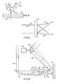
- Fig. 9 illustrates apparatus used in the fabrication of a holographic optical element, such as a grating, of the invention.
- a suitable coherent light source such as a laser 54 operating at a wavelength ⁇ C1
- Beam 60 which is used as the holographic reference beam, is passed through a collimating lens system 64 and is directed by mirrors 66 and 68 so as to impinge at an appropriate angle ⁇ 1 upon a recording medium 70.
- Any suitable known photosensitive substance can be used as the recording medium and, if required, appropriate means such as a glass plate 72 can be provided for its support.
- Beam 62 which is used as the signal beam is directed with a mirror 74 to a short focal length lens 76 whose output beam 78 is directed onto the recording medium 70.
- Beam 78 combines and interferes with reference beam 60 and that interference is recorded by the medium.
- beams of various wave- lenghts of light will be diffracted to the same angle by the holographic optical element if they are related to each other as the inverse of the ratio of their construction angles ⁇ i ... ⁇ j .
- the beams are normally incident on the element, they are made at one wavelength, and the general relationship from Equation (2) holds.
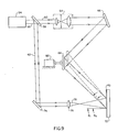
- the apparatus embodied in Fig. 9 is modified as shown in Fig. 10 by the insertion of an adjustable pinhole assembly 82 in the path of the signal beam.
- the embodiment of Fig. 10 will have the light source, beamsplitter, collimating lens system, and first mirror shown in Fig. 9 to produce a reference beam 60' and a signal beam 62'.
- Reference beam 60' is directed by adjustable mirror 68' to impinge at an appropriate angle ⁇ 1 upon a recording medium 70'.
- Signal beam 62' is directed with a mirror 74' to the pinhole assembly82 which comprises a short focal length lens 84 and a pinhole diaphragm 86.
- a suitable adjustment mechanism 88 is provided to selectively adjust the pinhole assembly in translation as indicated by directional arrows 90.
- the output beam 78' from the pinhole assembly is an expanding spherical wave. This beam is directed onto recording medium 70' at a focal length of F c1 so as to combine and interfere with the reference beam 60', that interference being recorded by the medium.
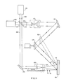
- the apparatus comprises a light source, such as a laser 100 operating at a wavelength ⁇ C1 , having an output beam 102 which is passed through a beamsplitter 104 to produce a reference beam 106 and a signal beam 108.
- Reference beam 106 is passed through a collimating lens system 110 and is directed. by mirrors 112 and 114 so as to impinge at an appropriate angle 0 1 upon a recording medium 116 which is mounted on a suitable support 118.
- Signal beam 108 is directed with a mirror 120 to an adjustable pinhole assembly 122, the output beam 124 thereof being directed onto the recording medium 116 to combine and interfere with reference beam 106.
- the pinhole assembly 122 will focus the signal beam 124 on recording medium 116 at a focus F C1 .
- a lens such as shown in the embodiment of Fig. 9 will be used instead of the pinhole assembly and adjustable means to.vary the focal length of the signal beam thus is not used.
- the second source of radiation at a wavelength ⁇ C2 can be a laser 126 whose output beam 128 is directed through the beamsplitter 104 such that the light passing therethrough is aligned with signal beam 108 and the light reflected therefrom is aligned with reference beam 106.
- the mirror 114 and the pinhole assembly 122 are adjusted to record the interference of the light beams at an angle of incidence 6 2 and a focal length F C2 . This procedure can be repeated to record the interferencesof the reference and signal beams at incidence angles ⁇ 3 ... ⁇ n and focal points of F C3 ...F Cn .
- the two wavelengths ⁇ C1 and ⁇ C2 will be diffracted by the holographic optical element developed from recording medium 116 such that the output therefrom is brought to substantially a common focal point as illustrated in Fig. 7.
- mirror 130 can be inserted into the beam.
- Suitable known means other than that shown can be utilized in this invention for producing controllably coherent radiation in a number of discrete wavelengths.
- Typical of such apparatus is the parametric converter or interacter disclosed in U.S. patent No. 4,250,465, granted to the inventor of the present invention and having the same assignee, which patent is incorporated herein by reference.
- Thick media is generally about 20 - 100 microns in thickness.
- reference beams are directed from either side of the recording plate normal to record the hologram, there is a unique angle producing a symmetrical pair of output beams of equal energy for which the Bragg angle is simultaneously satisfied.
- two independent focal points obtain (as shown in Fig. 12) from the thick media recording upon playback.
- the input beams 132 and 134, each of a different wavelength will be diffracted by the thick media holographic grating 136 as two output beams 138 and 140 having two independent focal points 142 and 144.
- the actual input angles depend upon the equations given herein previously, and upon the index of refraction of the material used for the thick media.
- n 1.54
- the reference beam incident angles for playback would be about ⁇ 10 degrees in order to obtain the conditions illustrated in Fig. 12.
Landscapes
- Physics & Mathematics (AREA)
- General Physics & Mathematics (AREA)
- Optics & Photonics (AREA)
- Holo Graphy (AREA)
- Diffracting Gratings Or Hologram Optical Elements (AREA)
Abstract
Description
- Be it known that I, Kenneth G. Leib, citizen of the United States of America and resident of Wantagh in the county of Nassau in the State of New York am the inventor of the above- entitled invention of which the following is a Specification:
- This invention relates to holographic optical elements and, more particularly, achromatic holographic optical elements and to a method of making the same.
- The term "hologram" is used to describe a photographic process that is becoming increasingly commonly used. Unlike oridnary photography, which consists of a recording of a three-dimensional scene as a two- dimensional image, the holographic process does not record an image of the object being photographed but, instead, records the reflected light waves themselves as they form an interference light pattern with a reference beam originating from the same source. Thus, the hologram contains all the information characterizing an object through which the light waves have passed or from which they have been reflected or scattered. If the object is an optical element such as a lens, matched filter, or diffraction grating, a hologram thereof will produce all the phenomena and attributes of that optical element ; representative characteristics of holographic optical elements are focal point, scale size, and deflection angle respectively.
- Conventionally, the hologram comprising the holographic optical element is made by using a laser of a particular wavelength, termed the construction (C) wavelength; and the playback (PB) or reconstruction wavelength of the holographic element is accomplished using a laser of the same or other wavelength. In conventional holography, if a laser of a different wavelength is used for the playback, the essential character of the holographic optical element, including deflection angle, focal point, and scale size, will change.
- In some applications of holographic optical elements it would be desirable-to retain a performance parameter regardless of the wavelength of the laser employed for the playback function. The subject invention is a means and the process of uniquely fabricating those means for substantially alleviating the wavelength dependency of holographic optical elements.
- In the construction of holographic optical elements, as shown in Fig. 1, an
input beam 10, called the signal beam S, is projected such that it is incident upon arecording medium 12 which can be coated or mounted on asuitable substrate 14, such as a glass plate, thin film, and the like. As is well known, therecording medium 12 can be a photographic emulsion, dichromated gelatin, a photopolymer, and the like. Simultaneously, and from the same source of coherent electromagnetic radiation, which source preferably is a laser, asecond beam 16, called the reference beam R, is directed at an angle θ1, so that it is incident upon therecording medium 12 such that it overlaps thesignal beam 10 at the medium. The result is an optical interference which is recorded in the medium as an amplitude or phase distribution of closely spaced lines. This line array may take various forms such as an amplitude distribution ofclear regions 18 and absorbing 20 regions in therecording medium 12 as- illustrated in cross section in Fig. 2.; or the phase distribution caused by difference in the indices ofrefraction 22 in therecording medium 12 as shown in Fig. 3; or spatial orrelief variations 24 in the surface of therecording medium 12 as shown in Fig. 4. As is well known, each of these forms represents a different phenomenon: the firs absorption via silver halides; the second, diffraction through refractive index changes; and the third, diffraction through variations in surface relief. In the latter case, absorptive or refractive index variation regions my also accompany the surface relief pattern of the recording medium or plate. - In the optical interference phenomenon shown in Fig. 1, the spacing of the optical interference lines, also known as the fringe lines, is dertermined by the equation

signal beam 10 is normal to the recording plate. - When the latter condition does not prevail, the general expression

- For a complex or extended object, Equation (1a) would be more appropriately expressed as

- If a
reference beam 26 at a different angle 82 but same wavelength is used, the recorded fringe pattern will be at a different fringe spacing, i.e.,
- With reference now to Fig. 5, assume that the
input beam 28 which is incident upon arecording plate 30 is a combination of two wavelengths and, further that the incident beam has been recorded and the recording medium suitably processed. In the reconstruction process, the wavelengths comprising the input beam can be designated λPBI, λPB2. One of the two wavelengths can be the construction wavelength λI, but such condition is not essential and, for the purposes of this exposition, the assumption can be made that it is not. Upon playback, the norma condition is that the different wavelengths will be diffracted through different angles. Thus, theoutput beam 32 of λPBI of theinput beam 28 will be diffracted through an angle ø andoutput beam 34 of λPB2 ofinput beam 28 will be diffracted through an angle ω. - In the construction of an achromatic optical element, such as a grating, the question is whether or not two wavelengths can be simultaneously incident upon the grating or similar diffraction element (at θS = O) and still give the same angle of diffraction.
- The diffraction equation is

- Since a common angle, D, is desired


- In other words, two wavelengths will be diffracted to the same angle D by the grating if they are related to each other as the inverse of the ratio of the sines of their construction angles. This is extendable to any number of wavelengths provided:
- (a) the beams are normally incident on the grating,
- (b) they are made at one wavelength, λ1,
- (c) the general relationship

- Consider-now the relationship which holds for the focal length of a holographic lens (HL)

- For two wavelengths,


- Since it has been shown above that λCI= λPBI


- To give a specific example having the chosen parameters of λC = 4880 A FC1= 360 mm θ1= 30° then if

- With reference now to Fig. 6, one
reference beam 36 is shown interacting at arecording plate 38 with onesignal beam 40 whose constructionfocal length 42 is FC1. A second signal beam 4 whosefocal length 46 is FC2 also interacts at therecording plate 38 withreference beam 36 to produce an interference patter in the plate.Beams beam input beams focal point 52. - Typically, the recording medium used in the holographic process is about 1-20 microns in thickness. However, there are advantages to using what is known as "thick media", generally about 20-100 microns in thickness, for the process. Thick media for recording gratings is characterized by Klein's "Q" criteria where


- When a grating is recorded in a thick medium, the angle of incidence upon playback must be considered as well as the grating spacing and the angle of incidence based upon the spacing only. This is due to the Bragg effect. Incident angles obeying the Bragg law are highly efficient beams; those which do not are inefficient and may be attenuated. Bragg's law is

- Consider Fig. 8. When two
beams fringes 96 in thethick recording medium 97 are formed and the playback angle for maximum efficiency must be θPB1 (98) where θPB1 is determined from Equation (4):
- Suppose a second set of angles is used (and initially a second wavelength); then

- or using Equation (5) for both cases, we end with


- satisfied by eC2 = 10°, θC2 = 27°18' and many other combinations. A Common playback angle is determined from Equation (5) and is Sin -1.325 = 18°35'. It should be noted that one cannot arbitra- rily set θC2, θC2 and have a playback angle common with the playback of construction angles eCl, θCl.
- In the prior art, E. N. Leith, U. S. Patent No. 3.586.412 discloses a method for constructing holographic lens in which a single, three-dimensional recording medium is exposed to two intersecting input beams at different angles to, in effect, scan an object, such that individual unaberrated zone plates are constructed in the medium for each angle of exposure so that a composite image of the object without significant aberration is obtainable. Leith, it is seen, also implies use of his lens at multiple wavelengths, but does not specify the unique conditions necessary for obtaining achromatic playback. In the prior art, R. S. Schools et al., U. S. patent No. 3.503.050, disclose an improvement in the known Lippmann porcess. In the Schools et al. system interfering waves of coherentlight sensitize a layer of a photosensitive emulsion at antinodes of the standing waves throughout the thickness of the emulsion to form a periodic structure of reflecting surfaces. A plurality of such structures are formed at any one point in the emulsion at differe t angles and are read out by the angle of reflected light..However, as is the case with Leith, Schools et al do not demonstrate that the beam angles as recorded must be a specified unique set of angles so as to enable an assemble of wavelengths. or "white" light, to have a common focal point. Nor do these prior art disclosures teach that a specific arrangement of fringes on a non- thick recording medium surface must be specifically as prescribed for white light playback.
- It is thus a principal object of the invention to provide holographic optical elements which operate at a multiplicity of wavelengths and which have reduced aberrations. It is a concurrent object of the invention to provide a method for producing such achromatic holographic optical elements.
- It is another object of the invention to employ a "thick" recording medium such that a symmetrical pair of output beams having two independent focal points are produced with a single input beam.
- For the purpose of illustrating the invention, there is shown in the drawings the forms which are presently preferred; however, it should be understood that the invention is not necessaril limited to the precise arrangements and instrumentalities here shown.
- Fig. 1 is a diagrammatic view showing the optical inputs into the recording medium used in constructing a holographic optical element;
- Fig. 2-4 are cross-sectional views showing interference phenomenon associated with the various types of the recording medium of Fig. 1;
- Fig. 5 is a diagrammatic view showing diffraction characteristics of a conventional holographic optical element;
- Fig. 6 is a diagrammatic view showing the optical input into the recording medium used in fabricating holographic optical elements in accordance with the invention;
- Fig. 7 is a diagrammatic view showing the diffraction characteristics of holographic optical elements of the invention;
- Fig. 8 is a diagrammatic view showing interference characteristics of thick recording media in accordance with the invention;
- Fig. 9 is a diagrammatic view of a preferred embodiment of apparatus of the invention;
- Fig. 10 is a fragmentary diagrammatic view of another embodiment of apparatus of the invention;
- Fig. 11 is a diagrammatic view of yet another embodiment of apparatus of the invention; and
- Fig. 12 is a diagrammatic view showing the diffraction characteristics of thick media in accordance with the invention.
- Having now more particular reference to the drawings, Fig. 9 illustrates apparatus used in the fabrication of a holographic optical element, such as a grating, of the invention. A suitable coherent light source such as a
laser 54 operating at a wavelength λC1, has anoutput beam 56 which is passed through abeamsplitter 58 to producebeams Beam 60, which is used as the holographic reference beam, is passed through a collimating lens system 64 and is directed bymirrors recording medium 70. Any suitable known photosensitive substance can be used as the recording medium and, if required, appropriate means such as aglass plate 72 can be provided for its support.Beam 62, which is used as the signal beam is directed with amirror 74 to a shortfocal length lens 76 whoseoutput beam 78 is directed onto therecording medium 70.Beam 78 combines and interferes withreference beam 60 and that interference is recorded by the medium. - It will be recognized that the apparatus described to this point is essentially that used in the known process for fabricating conventional holographic optical elements. In the process of the present invention, however, once
beam 60 is recorded at an angle of incidence el, themirror 68 is adjusted by suitable adjustment means 80 andbeam 60 is recorded interfering withbeam 78 at an incidence angle 02. As required, this procedure can be repeated to record interference at incidence angles ⊖3...⊖n. - It will be appreciated that, in accordance with the exposition of the invention given previously herein, beams of various wave- lenghts of light will be diffracted to the same angle by the holographic optical element if they are related to each other as the inverse of the ratio of their construction angles ⊖i...⊖j. Provided also, as stated previously, that the beams are normally incident on the element, they are made at one wavelength, and the general relationship

- To provide the variations in focal length required during the construction of an achromatic lens of the invention, the apparatus embodied in Fig. 9 is modified as shown in Fig. 10 by the insertion of an
adjustable pinhole assembly 82 in the path of the signal beam. Thus, although not shown, the embodiment of Fig. 10 will have the light source, beamsplitter, collimating lens system, and first mirror shown in Fig. 9 to produce a reference beam 60' and a signal beam 62'. Reference beam 60' is directed by adjustable mirror 68' to impinge at an appropriate angle ⊖1 upon arecording medium 70'. Signal beam 62' is directed with a mirror 74' to the pinhole assembly82 which comprises a shortfocal length lens 84 and apinhole diaphragm 86. Asuitable adjustment mechanism 88 is provided to selectively adjust the pinhole assembly in translation as indicated bydirectional arrows 90. The output beam 78' from the pinhole assembly is an expanding spherical wave. This beam is directed ontorecording medium 70' at a focal length of Fc1 so as to combine and interfere with the reference beam 60', that interference being recorded by the medium. the - In the process of invention, once reference beam 60' is recorded at an angle of incidence e1 and signal beam 62' at a focus Fc1, the mirror 68' and the
pinhole assembly 82 are adjusted by their adjustment means 80' and 88 respectively and beam 60' is recorded at an angle of incidence ⊖2 and beam 62' at a focus Fc2. As required, this procedure can be repeated to record interference of beams 60' and 62' at incidence angles 03 ... en and focuses of FC3..FCn. - The preceding description details the construction of achromatic holographic optical elements using coherent electromagnetic radiation of a single wavelength; however, radiation of more than one wavelength can be used to construct the optical elements provided the mathematical relationships of the invention are adhered to. With reference now to Fig. 11, the apparatus comprises a light source, such as a
laser 100 operating at a wavelength À C1, having anoutput beam 102 which is passed through abeamsplitter 104 to produce areference beam 106 and asignal beam 108.Reference beam 106 is passed through acollimating lens system 110 and is directed. bymirrors recording medium 116 which is mounted on asuitable support 118.Signal beam 108 is directed with amirror 120 to anadjustable pinhole assembly 122, theoutput beam 124 thereof being directed onto therecording medium 116 to combine and interfere withreference beam 106. As will be understood from the preceding description of the other embodiments of the invention, if the optical element being constructed is a lens, thepinhole assembly 122 will focus thesignal beam 124 on recording medium 116 at a focus FC1. If the optical element being constructed is a grating, a lens such as shown in the embodiment of Fig. 9 will be used instead of the pinhole assembly and adjustable means to.vary the focal length of the signal beam thus is not used. The second source of radiation at a wavelength λC2 can be alaser 126 whoseoutput beam 128 is directed through thebeamsplitter 104 such that the light passing therethrough is aligned withsignal beam 108 and the light reflected therefrom is aligned withreference beam 106. When the output of thesecond laser 126 is recorded, themirror 114 and thepinhole assembly 122 are adjusted to record the interference of the light beams at an angle of incidence 62 and a focal length FC2. This procedure can be repeated to record the interferencesof the reference and signal beams at incidence angles ⊖3...⊖n and focal points of FC3...FCn. As has been discussed previously herein, if the general relationships

- Instead of adjusting
mirror 114 to vary the angle of incidence ofreference beam 106 for a second or subsequent wavelengths, additional mirrors such asmirror 130 can be inserted into the beam. Suitable known means other than that shown can be utilized in this invention for producing controllably coherent radiation in a number of discrete wavelengths. Typical of such apparatus is the parametric converter or interacter disclosed in U.S. patent No. 4,250,465, granted to the inventor of the present invention and having the same assignee, which patent is incorporated herein by reference. - There are advantages to using thick media in the process. Thick media, as discussed previously, is generally about 20 - 100 microns in thickness. When reference beams are directed from either side of the recording plate normal to record the hologram, there is a unique angle producing a symmetrical pair of output beams of equal energy for which the Bragg angle is simultaneously satisfied. Thus, two independent focal points obtain (as shown in Fig. 12) from the thick media recording upon playback. As shown, the input beams 132 and 134, each of a different wavelength will be diffracted by the thick media holographic grating 136 as two
output beams focal points - During the construction of the holographic element, the actual input angles depend upon the equations given herein previously, and upon the index of refraction of the material used for the thick media. For example, dichromated gelatin which has an inde of refraction, n = 1.54; the reference beam incident angles for playback would be about ± 10 degrees in order to obtain the conditions illustrated in Fig. 12.
- Although shown and described in what_are believed to be the most practical and preferred embodiments, it is apparent that departures from the specific methods and designs described and shown will suggest themselves to thoseskilled in the art and may be made without departing from the spirit and scope of the invention. I, therefore, do not wish to restrict myself to the particular constructions described and illustrated, but desire to avail myself of all modifications that may fall within the scope of the appended claims.
- Having thus described my invention, what I claim is:
Claims (15)


Priority Applications (2)
| Application Number | Priority Date | Filing Date | Title |
|---|---|---|---|
| DE8484104101T DE3479608D1 (en) | 1984-04-12 | 1984-04-12 | Achromatic holographic element |
| AT84104101T ATE46041T1 (en) | 1984-04-12 | 1984-04-12 | ACHROMATIC HOLOGRAPHIC ELEMENT. |
Applications Claiming Priority (1)
| Application Number | Priority Date | Filing Date | Title |
|---|---|---|---|
| US06/352,362 US4447111A (en) | 1982-02-25 | 1982-02-25 | Achromatic holographic element |
Publications (3)
| Publication Number | Publication Date |
|---|---|
| EP0157895A2 true EP0157895A2 (en) | 1985-10-16 |
| EP0157895A3 EP0157895A3 (en) | 1986-12-10 |
| EP0157895B1 EP0157895B1 (en) | 1989-08-30 |
Family
ID=23384820
Family Applications (1)
| Application Number | Title | Priority Date | Filing Date |
|---|---|---|---|
| EP84104101A Expired EP0157895B1 (en) | 1982-02-25 | 1984-04-12 | Achromatic holographic element |
Country Status (4)
| Country | Link |
|---|---|
| US (1) | US4447111A (en) |
| EP (1) | EP0157895B1 (en) |
| AU (1) | AU563984B2 (en) |
| IN (1) | IN160504B (en) |
Cited By (2)
| Publication number | Priority date | Publication date | Assignee | Title |
|---|---|---|---|---|
| WO2017035283A1 (en) * | 2015-08-24 | 2017-03-02 | Akonia Holographics, Llc | Skew mirrors, methods of use, and methods of manufacture |
| US10649143B2 (en) | 2016-06-20 | 2020-05-12 | Akonia Holographics Llc | Polarization management |
Families Citing this family (21)
| Publication number | Priority date | Publication date | Assignee | Title |
|---|---|---|---|---|
| JPS59160134A (en) * | 1983-03-04 | 1984-09-10 | Canon Inc | Illuminating optical system |
| US4802719A (en) * | 1983-08-22 | 1989-02-07 | Farrand Optical Co. | Infra-red laser shield |
| JPS60108802A (en) * | 1983-11-18 | 1985-06-14 | Fuji Photo Film Co Ltd | Method and device for optical beam synthesis |
| US4735486A (en) * | 1985-03-29 | 1988-04-05 | Grumman Aerospace Corporation | Systems and methods for processing optical correlator memory devices |
| US4752130A (en) * | 1986-10-24 | 1988-06-21 | The University Of Rochester | Optical systems utilizing a volume transmission diffraction element to provide wavelength tuning |
| US4950050A (en) * | 1987-06-19 | 1990-08-21 | Grumman Aerospace Corporation | Optical target recognition system |
| US4930847A (en) * | 1987-07-09 | 1990-06-05 | Environmental Research Institute Of Michigan | Multicolor holographic element and apparatus for head-up display applications |
| FR2723216A1 (en) * | 1987-07-28 | 1996-02-02 | Thomson Csf | Convergent infrared diffracting objective esp for thermal camera |
| US4850662A (en) * | 1988-02-12 | 1989-07-25 | Saginaw Valley State University | HOE and indirect method of constructing same |
| US4941733A (en) * | 1989-04-07 | 1990-07-17 | Grumman Aerospace Corporation | Optical correlator system |
| US5128780A (en) * | 1989-08-30 | 1992-07-07 | Hughes Aircraft Company | Enhanced-resolution, multiply-exposed reflection hologram |
| US5272551A (en) * | 1989-10-03 | 1993-12-21 | Thomson-Csf | Optical system for the reproduction of color video images |
| FR2652656B1 (en) * | 1989-10-03 | 1991-12-06 | Thomson Csf | COLOR VIDEO IMAGE REPRODUCTION SYSTEM. |
| US5129041A (en) * | 1990-06-08 | 1992-07-07 | Grumman Aerospace Corporation | Optical neural network processing element with multiple holographic element interconnects |
| FR2699289B1 (en) * | 1992-12-15 | 1995-01-06 | Thomson Csf | Holographic projection screen and production method. |
| WO1995034832A1 (en) * | 1992-12-15 | 1995-12-21 | Thomson-Csf | Holographic projection screen and method for its production |
| US5606434A (en) * | 1994-06-30 | 1997-02-25 | University Of North Carolina | Achromatic optical system including diffractive optical element |
| JP2007193852A (en) * | 2004-03-30 | 2007-08-02 | Pioneer Electronic Corp | Hologram recording medium |
| KR20080014533A (en) * | 2006-08-11 | 2008-02-14 | 삼성전자주식회사 | Apparatus for controlling incident angle of reference beam and holographic information recording/reproducing apparatus |
| US9625878B2 (en) * | 2009-03-10 | 2017-04-18 | Drexel University | Dynamic time multiplexing fabrication of holographic polymer dispersed liquid crystals for increased wavelength sensitivity |
| US9752932B2 (en) | 2010-03-10 | 2017-09-05 | Drexel University | Tunable electro-optic filter stack |
Citations (2)
| Publication number | Priority date | Publication date | Assignee | Title |
|---|---|---|---|---|
| US3503050A (en) * | 1965-12-30 | 1970-03-24 | Ibm | Wave energy recording in radiation sensitive medium |
| US3680945A (en) * | 1970-10-23 | 1972-08-01 | Xerox Corp | Fabrication of refractive blazed holograms |
Family Cites Families (6)
| Publication number | Priority date | Publication date | Assignee | Title |
|---|---|---|---|---|
| US3405614A (en) * | 1965-12-01 | 1968-10-15 | Bell Telephone Labor Inc | Apparatus for producing a fly's eye lens |
| US3586412A (en) * | 1968-05-20 | 1971-06-22 | Battelle Development Corp | Holographic lens with aberration correction |
| US3630593A (en) * | 1970-05-08 | 1971-12-28 | Bell Telephone Labor Inc | Holographically produced image arrays for photolithography |
| US3970358A (en) * | 1975-01-20 | 1976-07-20 | Harris Corporation | Coherent, quasi-monochromatic light source |
| US4017158A (en) * | 1975-03-17 | 1977-04-12 | E. I. Du Pont De Nemours And Company | Spatial frequency carrier and process of preparing same |
| US4250465A (en) * | 1978-08-29 | 1981-02-10 | Grumman Aerospace Corporation | Radiation beam deflection system |
-
1982
- 1982-02-25 US US06/352,362 patent/US4447111A/en not_active Expired - Lifetime
-
1984
- 1984-04-12 EP EP84104101A patent/EP0157895B1/en not_active Expired
- 1984-04-13 AU AU26804/84A patent/AU563984B2/en not_active Ceased
- 1984-04-16 IN IN324/DEL/84A patent/IN160504B/en unknown
Patent Citations (2)
| Publication number | Priority date | Publication date | Assignee | Title |
|---|---|---|---|---|
| US3503050A (en) * | 1965-12-30 | 1970-03-24 | Ibm | Wave energy recording in radiation sensitive medium |
| US3680945A (en) * | 1970-10-23 | 1972-08-01 | Xerox Corp | Fabrication of refractive blazed holograms |
Non-Patent Citations (4)
| Title |
|---|
| APPLIED OPTICS, vol. 15, no. 2, February 1976, pages 542-545; S. BENNETT: "Achromatic combinations of hologram optical elements" * |
| JOURNAL OF THE OPTICAL SOCIETY OF AMERICA, vol. 58, no. 7, July 1968, pages 871-874, New York, US; K.A. SNOW et al.: "Production of partially achromatic zone plates by holographic techniques" * |
| JOURNAL OF THE OPTICAL SOCIETY OF AMERICA, vol. 65, no.6, June 1975, pages 724-729, New York, US; S.K. CASE: "Coupled-wave theory for multiply exposed thick holographic gratings" * |
| OPTICS AND SPECTROSCOPY, vol. 44, no. 1, January 1978, pages 95-97, The Optical Society of America, New York, US; K.S. MUSTAFIN: "Design of achromatic hologram lens systems using the principle of tautochronism of rays" * |
Cited By (10)
| Publication number | Priority date | Publication date | Assignee | Title |
|---|---|---|---|---|
| WO2017035283A1 (en) * | 2015-08-24 | 2017-03-02 | Akonia Holographics, Llc | Skew mirrors, methods of use, and methods of manufacture |
| US9891363B2 (en) | 2015-08-24 | 2018-02-13 | Akonia Holographics Llc | Skew mirrors, methods of use, and methods of manufacture |
| CN108139560A (en) * | 2015-08-24 | 2018-06-08 | 阿科尼亚全息有限责任公司 | Inclined mirrors, application method and manufacturing method |
| US10180520B2 (en) | 2015-08-24 | 2019-01-15 | Akonia Holographics, Llc | Skew mirrors, methods of use, and methods of manufacture |
| US10185069B2 (en) | 2015-08-24 | 2019-01-22 | Akonia Holographics, Llc | Skew mirrors, methods of use, and methods of manufacture |
| CN108139560B (en) * | 2015-08-24 | 2021-02-26 | 阿科尼亚全息有限责任公司 | Skew mirror, method of use and method of manufacture |
| CN112748487A (en) * | 2015-08-24 | 2021-05-04 | 阿科尼亚全息有限责任公司 | Skew mirror, method of use and method of manufacture |
| US11054564B2 (en) | 2015-08-24 | 2021-07-06 | Akonia Holographies LLC | Skew mirrors, methods of use, and methods of manufacture |
| US10649143B2 (en) | 2016-06-20 | 2020-05-12 | Akonia Holographics Llc | Polarization management |
| US10698162B2 (en) | 2016-06-20 | 2020-06-30 | Akonia Holographics Llc | Polarization management |
Also Published As
| Publication number | Publication date |
|---|---|
| EP0157895B1 (en) | 1989-08-30 |
| AU563984B2 (en) | 1987-07-30 |
| US4447111A (en) | 1984-05-08 |
| AU2680484A (en) | 1985-10-17 |
| EP0157895A3 (en) | 1986-12-10 |
| IN160504B (en) | 1987-07-18 |
Similar Documents
| Publication | Publication Date | Title |
|---|---|---|
| EP0157895A2 (en) | Achromatic holographic element | |
| US4245882A (en) | Doubly modulated on-axis thick hologram optical element | |
| Close | Holographic optical elements | |
| US4904033A (en) | Method for constructing holograms | |
| US4824193A (en) | Holographic multiplexer/demultiplexer and its manufacturing method | |
| US3807829A (en) | Extended-field holographic lens arrays | |
| US4469407A (en) | Laser apodizing filter | |
| EP0000810A1 (en) | Method of and apparatus for forming focusing diffraction gratings for integrated optics | |
| GB1591170A (en) | Photographic camera with a holographic or kinoform focusing screen | |
| US4575192A (en) | Method of bragg angle adjustments for copying holograms | |
| EP0152433A1 (en) | Method of producing a filtered beam of light. | |
| US5189532A (en) | Edge-illuminated narrow bandwidth holographic filter | |
| US4392709A (en) | Method of manufacturing holographic elements for fiber and integrated optic systems | |
| JPH0627965B2 (en) | Hologram production method | |
| US4461533A (en) | Forming and reading holograms | |
| KR910007718B1 (en) | Achromatic holographic element | |
| KR19990067888A (en) | Total internal reflection(tir) holographic apparatus and methods and optical assemblies therein | |
| Prongué et al. | HOE for clock distribution in integrated circuits: experimental results | |
| EP0207132B1 (en) | Method of producing a gaussian laser beam filter | |
| JP3171013B2 (en) | Method and apparatus for producing article comprising diffraction grating | |
| JPH0250613B2 (en) | ||
| JPH058830B2 (en) | ||
| EP0365259A2 (en) | Method and apparatus for the use of holographic optical elements | |
| JP3003348B2 (en) | Optical lens and manufacturing method thereof | |
| Słaby et al. | Cascaded phase Fourier holograms |
Legal Events
| Date | Code | Title | Description |
|---|---|---|---|
| PUAI | Public reference made under article 153(3) epc to a published international application that has entered the european phase |
Free format text: ORIGINAL CODE: 0009012 |
|
| AK | Designated contracting states |
Designated state(s): AT BE CH DE FR GB IT LI NL SE |
|
| PUAL | Search report despatched |
Free format text: ORIGINAL CODE: 0009013 |
|
| AK | Designated contracting states |
Kind code of ref document: A3 Designated state(s): AT BE CH DE FR GB IT LI NL SE |
|
| 17P | Request for examination filed |
Effective date: 19870202 |
|
| 17Q | First examination report despatched |
Effective date: 19880408 |
|
| GRAA | (expected) grant |
Free format text: ORIGINAL CODE: 0009210 |
|
| AK | Designated contracting states |
Kind code of ref document: B1 Designated state(s): AT BE CH DE FR GB IT LI NL SE |
|
| PG25 | Lapsed in a contracting state [announced via postgrant information from national office to epo] |
Ref country code: SE Effective date: 19890830 Ref country code: NL Effective date: 19890830 Ref country code: LI Effective date: 19890830 Ref country code: IT Free format text: LAPSE BECAUSE OF FAILURE TO SUBMIT A TRANSLATION OF THE DESCRIPTION OR TO PAY THE FEE WITHIN THE PRESCRIBED TIME-LIMIT;WARNING: LAPSES OF ITALIAN PATENTS WITH EFFECTIVE DATE BEFORE 2007 MAY HAVE OCCURRED AT ANY TIME BEFORE 2007. THE CORRECT EFFECTIVE DATE MAY BE DIFFERENT FROM THE ONE RECORDED. Effective date: 19890830 Ref country code: CH Effective date: 19890830 Ref country code: BE Effective date: 19890830 Ref country code: AT Effective date: 19890830 |
|
| REF | Corresponds to: |
Ref document number: 46041 Country of ref document: AT Date of ref document: 19890915 Kind code of ref document: T |
|
| REF | Corresponds to: |
Ref document number: 3479608 Country of ref document: DE Date of ref document: 19891005 |
|
| ET | Fr: translation filed | ||
| REG | Reference to a national code |
Ref country code: CH Ref legal event code: PL |
|
| NLV1 | Nl: lapsed or annulled due to failure to fulfill the requirements of art. 29p and 29m of the patents act | ||
| PLBE | No opposition filed within time limit |
Free format text: ORIGINAL CODE: 0009261 |
|
| STAA | Information on the status of an ep patent application or granted ep patent |
Free format text: STATUS: NO OPPOSITION FILED WITHIN TIME LIMIT |
|
| 26N | No opposition filed | ||
| PGFP | Annual fee paid to national office [announced via postgrant information from national office to epo] |
Ref country code: GB Payment date: 19920320 Year of fee payment: 9 |
|
| PGFP | Annual fee paid to national office [announced via postgrant information from national office to epo] |
Ref country code: FR Payment date: 19920408 Year of fee payment: 9 |
|
| PGFP | Annual fee paid to national office [announced via postgrant information from national office to epo] |
Ref country code: DE Payment date: 19920514 Year of fee payment: 9 |
|
| PG25 | Lapsed in a contracting state [announced via postgrant information from national office to epo] |
Ref country code: GB Effective date: 19930412 |
|
| GBPC | Gb: european patent ceased through non-payment of renewal fee |
Effective date: 19930412 |
|
| PG25 | Lapsed in a contracting state [announced via postgrant information from national office to epo] |
Ref country code: FR Effective date: 19931229 |
|
| PG25 | Lapsed in a contracting state [announced via postgrant information from national office to epo] |
Ref country code: DE Effective date: 19940101 |
|
| REG | Reference to a national code |
Ref country code: FR Ref legal event code: ST |