EP0147655A2 - Miniature squid susceptometer - Google Patents
Miniature squid susceptometer Download PDFInfo
- Publication number
- EP0147655A2 EP0147655A2 EP84114424A EP84114424A EP0147655A2 EP 0147655 A2 EP0147655 A2 EP 0147655A2 EP 84114424 A EP84114424 A EP 84114424A EP 84114424 A EP84114424 A EP 84114424A EP 0147655 A2 EP0147655 A2 EP 0147655A2
- Authority
- EP
- European Patent Office
- Prior art keywords
- squid
- pick
- loops
- susceptometer
- field coil
- Prior art date
- Legal status (The legal status is an assumption and is not a legal conclusion. Google has not performed a legal analysis and makes no representation as to the accuracy of the status listed.)
- Granted
Links
Images
Classifications
-
- G—PHYSICS
- G01—MEASURING; TESTING
- G01R—MEASURING ELECTRIC VARIABLES; MEASURING MAGNETIC VARIABLES
- G01R33/00—Arrangements or instruments for measuring magnetic variables
- G01R33/12—Measuring magnetic properties of articles or specimens of solids or fluids
- G01R33/16—Measuring susceptibility
-
- G—PHYSICS
- G01—MEASURING; TESTING
- G01R—MEASURING ELECTRIC VARIABLES; MEASURING MAGNETIC VARIABLES
- G01R33/00—Arrangements or instruments for measuring magnetic variables
- G01R33/02—Measuring direction or magnitude of magnetic fields or magnetic flux
- G01R33/035—Measuring direction or magnitude of magnetic fields or magnetic flux using superconductive devices
- G01R33/0354—SQUIDS
- G01R33/0358—SQUIDS coupling the flux to the SQUID
-
- Y—GENERAL TAGGING OF NEW TECHNOLOGICAL DEVELOPMENTS; GENERAL TAGGING OF CROSS-SECTIONAL TECHNOLOGIES SPANNING OVER SEVERAL SECTIONS OF THE IPC; TECHNICAL SUBJECTS COVERED BY FORMER USPC CROSS-REFERENCE ART COLLECTIONS [XRACs] AND DIGESTS
- Y10—TECHNICAL SUBJECTS COVERED BY FORMER USPC
- Y10S—TECHNICAL SUBJECTS COVERED BY FORMER USPC CROSS-REFERENCE ART COLLECTIONS [XRACs] AND DIGESTS
- Y10S505/00—Superconductor technology: apparatus, material, process
- Y10S505/825—Apparatus per se, device per se, or process of making or operating same
- Y10S505/842—Measuring and testing
- Y10S505/843—Electrical
- Y10S505/845—Magnetometer
- Y10S505/846—Magnetometer using superconductive quantum interference device, i.e. squid
Definitions
- This invention relates to a new, very sensitive miniature SQUID susceptometer for measuring properties of a very small sample, and more particularly to such an instrument employing small area junctions in the SQUID and small pick-up loops, all of which are integrated in a planar structure on a single substrate and wherein the scale for the sample size is set by the same parameters that limit the size of the junctions in the SQUID.
- SQUIDs Superconducting quantum interference devices
- SQUIDs Superconducting quantum interference devices
- gradiometers magnetometers
- galvanometers galvanometers
- an input coil is used to couple the signal from the pick-up loop to the SQUID to allow shielding of the SQUID functions from the external magnetic field.
- the RF SQUID is equivalent to a superconducting ring haying a single weak link or Josephson tunnel device coupled to a resonant circuit driven by a constant current source at a selected RF frequency. Both the Q-factor and the resonant frequency of the circuit are modified by the coupling to the SQUID depending on the magnetic flux through the ring.
- a dc SQUID is one in which a superconducting loop incorporates multiple junctions, for example, two Josephson junctions, in parallel. For this type of SQUID, the maximum super current across the device, the critical current, is a periodic function of the magnetic flux enclosed is the loop.
- Dc SQUIDs are usually operated in a resistive mode at constant current in which the total current is due in part to superconducting electrons and in part to normal electrons. A voltage signal is then picked off a convenient operating point of the corresponding current-voltage curve. Changes in this voltage are a function of changes in the magnetic flux contained within the loop.
- Planar coupling schemes have also been introduced to provide more efficient coupling of high resolution SQUIDs to input circuits having useful inductances of the order of 1 ⁇ H.
- Representative examples of these planar coupling schemes include the following references:
- Such commercial susceptometers consist of a roughly balanced wire wound gradiometer (no low temperature balance adjustment) connected to an approximately 2 ⁇ H input coil of a conventional RF SQUID.
- Static ambient fields of up to approximately 50kG are applied with a superconducting solenoid magnet.
- the magnetic field is turned on with the gradiometer coils driven normal by a heater. With the field at the desired value, the heater is turned off, trapping some flux but no current in the gradiometer pick-up loops/input coil circiut.
- the RF SQUID in the meantime, is highly shielded from the applied magnetic field.
- the field coil gradiometer pick-up loops are all within a large superconducting shield for electrical isolation.
- the sample to be measured is periodically (every few seconds to a minute) moved into and out of one of the gradiometer pick-up loops.
- the amplitude of the signal registered by the SQUID is proportional to the susceptibility of the sample.
- the sample chamber is thermally isolated from the cryogenic environment so that the sample temperature can be varied over a wide range.
- the roughly balanced gradiometer pick-up coil configuration helps with noise rejection, although in a more highly shielded environment a straight magnetometer arrangement would work equally well.
- This miniature, integrated susceptometer includes pick-up loops which are part of the SQUID loop and which are located in the high magnetic field region of the instrument.
- the Josephson elements (junctions, weak links, etc.) of the SQUID are planar, as are the pick-up loops and the field coil loops used to apply a magnetic field to a sample located within the pick-up loops.
- the signal to be measured is generated locally within the pick-up loop forming a portion of the SQUID, where there is direct coupling of the sample to the SQUID loop.
- the size of the sample can range from slightly smaller than the loop size down to ⁇ 100 nm, or possibly less.
- the dc SQUID is comprised of two series wired (square) pick-up loops that are wound in opposite sense over a hole in a superconducting ground plane. These pick-up loops (comprising a portion of the SQUID) are connected by wide, low inductance transmission lines to remotely located Josephson elements such as Josephson tunnel junctions or weak links.
- the Josephson elements are nonhysteretic and are typically shunted with a parallel shunt resistance.
- a field coil is provided for producing a magnetic field which intercepts the pick-up loops of the SQUID.
- a center tapped field coil takes a single (square) turn around each pick-up loop of the SQUID.
- An adjustable constant current source is provided across the terminals of the field coil, and a modulation current source is provided .to produce a current through one turn of the field coil to optimally flux-bias the SQUID.
- a bias current source is provided across the SQUID for dc biasing the Josephson elements of the SQUID to a proper operating point.
- Readout electronics can also be connected to the SQUID loop in order to read out the SQUID.
- the readout electronics can be comprises of conventional devices such as RF SQUIDs and FET read- out circuits.
- the miniature SQUID susceptometer of this invention is one which is integrated on a single substrate chip, all components of which are produced by planar lithographic techniques, and is designed for a single purpose: the measurement of properties of extremely small particles and thin films. It is generally comprised of a dc SQUID (where the pick-up loops of the susceptometer are portions of the SQUID loop) and a center-tapped field coil having a single turn around each of the SQUID pick- up loops.
- the loop portion of the dc SQUID is located in the high field region of the susceptometer, and the sample to be investigated produces a signal which is generated locally within one of the pick-up loops of the SQUID, so that the sample couples directly to the SQUID loop inductance.
- the signal is either transferred to the SQUID loop by an input circuit or the signal is generated externally and the SQUID is brought to the environment of the signal.
- the scale for the sample size is set by the pick-up loop size, which in turn is set by photolithographic considerations.
- the pick-up loops can be made very small and the range of sample size even smaller.
- the small low inductance pick-up loops couple well to small samples.
- the SQUID tunnel junctions can be made of extremely small size (again limited by photolithographic considerations) to enhance the intrinsic energy sensitivity.
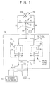
- the susceptometer is generally comprised of a dc SQUID 10, a field coil 12, means 14 for providing a bias current I B to the SQUID 10, means 16 for providing a modulation current to the field coil 12, means 18 for providing the field current If to the field coil 12, and a balance network 20 for applying current to the field coil 12 in order to balance out system asymmetries.
- SQUID read-out electronics 22 are also provided for detecting the state of the SQUID, which is an indication of the properties of the sample being investigated. Conventional read-out electronics can be used, such as a RF SQUID circuit of the type shown in M.B. Ketchen and J.M.
- Dc SQUID 10 includes two Josephson elements 24 and 26 in a superconducting loop including two series-wired square pick-up loops 28 and 30 wound in opposite electrical sense over a hole 32 in the superconducting ground plane 34. Loops 28 and 30 are connected by wide, low inductance transmission lines 36 and 38 to minimize the inductance of the dc SQUID 10.
- the Josephson elements 24 and 26 are preferrably Josephson tunnel junctions, such as edge junctions or planar junctions. However, other types of Josephson elements, such as weak links, can be used. Junctions 24 and 26 are non-hyszeretic and generally have this characteristic due to a parallel shunt resistance across each of the junctions 24 and 26. These techniques are well known in the art.
- Superconducting Josephson junctions 24 and 26 are located over the ground plane in order to provide shielding from the magnetic fields due to currents in the field coils 12 and from samples placed within the pick-up loops 28 and 30.
- the pick-up loops 28 and 30 are portions of the SQUID 10 and are located over a hole in the ground plane. This means that they will be located in a high field region of the susceptometer, in contrast with prior design where the entire SQUID was located in a shielded region.
- the field coil 12 is a center tapped coil which includes a single turn 40 around pick-up loop 28 and another single turn 42 around pick-up loop 30.
- a field current If is produced by the field current source 18, including a variable voltage source 44 and the resistors R1, R2, R3, R4, and R5. While dc currents are typically applied to the field coil, ac currents can be applied if the voltage source 44 is an ac voltage source.
- the resistive balancing network 20 uses the adjustable center tap 46 to balance out system asymmetries, such as occur because of the cross-over of the transmission lines 36 and 38 used to provide the opposite sense windings of pick-up loops 28 and 30. Another part of the imbalance is associated with direct coupling between the field coil leads and the pick-up loops 28 and 30.
- the balance of the susceptometer is easily adjusted electrically by the resistive network 20 tnat utilizes the center tap 48 of the field coil 12.
- voltage source 44 can be an ac source so that the field coil 12 can be driven at frequencies greater than lkHz in order to minimize the effects of 1/f noise.
- Existing RF SQUIDs or FET readout schemes with dynamic ranges of ⁇ 10 4 will be completely adequate to read out the dc SQUID 10.
- SQUID suscep I ometers The operation of SQUID suscep I ometers is well known in the art and will not be described in detail here. It should be understood that the instrument depicted in FIG. 1 can be used for the measurement of many properties of very small samples and can be used in many different applications, including measurement of sample properties and other applications, such as biological studies, if very close coupling (of the order of the pick-up loop diameter) can be obtained between the pick-up loop and the biological cell to be examined.
- the precise application and mode of operation of the instrument of FIG. 1 is not a critical part of this invention, it being understood that those of skill in the art will utilize this highly sensitive instrument to advantage in many different applications, and in many different ways.
- the temperature range of operation is limited on the high side to the temperature where the SQUID will not function (i.e., will go normal) and on the low side to the temperature at which the resistive shunts may go superconducting.
- a fixture which thermally isolates the sample from the SQUID where the fixture is brought very close to the SQUID to couple the sample to the SQUID.
- a representative mode of operation for the instrument of FIG. 1 is the following:
- the susceptometer is typically mounted on a ceramic header.
- the contact pads are connected to header pins and the header is plugged into a receptacle that is wired into the readout electronics, such as a RF SQUID preamplifier circuit.
- the SQUID is biased with current IS and a flux MI C where the modulation current I c is applied to one turn 42 of the field coil 12.
- Source 14 (I B ) sets the current through the Josephson elements, and source 16 (I ) sets the magnetic flux through the pickup loop 30 to adjust the flux bias.
- a current If can be passed through field coil 12. This produces a magnetic field in the center of the pick-up loops 28 and 30.
- the susceptometer is then balanced using the resistive balance network 20 to compensate for asymmetry in the design associated with the opposite sense configuration of the pick-up loops 28 and 30, and the direct coupling that occurs between the field coil leads and the pick-up loops 28 and 30.
- thin film samples can be mounted by direct deposition onto the susceptometer substrate.
- a discrete small particle on the other hand, needs to be physically placed in a pick-up loop 28 or 30 and kept there.
- this instrument can be used at cryogenic temperatures for the study of temperature dependent susceptibility as well as magnetic noise in thin film samples and for the study of discrete particles having volumes in the range of 10 3 ⁇ m 2 to less than 10 -3 ⁇ m 3 .
- Measurements on small particles are generally made using a vacuum can cryoinsert in which the header holding the susceptometer chip (FIG. 1) is mounted horizontally on a copper block. The chip is thermally grounded to the copper block, which has a time constant of approximately 100 sec.
- the sample chamber is not thermally isolated from the cryogenic environment, the sample temperature can be varied from the bath temperature up to the maximum operating temperature of the SQUID. However, if the sample is thermally isolated from the SQUID, its temperature could be varied over a much wider range, as noted previously.
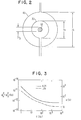
- FIG. 2 is a simplified sample particle-loop geometry used to calculate the susceptometer response to the presence of the sample in one of the pick-up loops 28 or 30.
- the sample 50 to be investigated is a spherical particle of radius r 0 at the center of the'SQUID pick-up loop 30 and the field loop 42.
- SQUID loop 30 and field loop 42 are approximated by circular loops in FIG. 2, to aid the mathematical analysis.
- Circular pick-up loop 30 has a diameter 2a and is completely surrounded by the field loop 42 of diameter 2b.
- a current IF through the field coil generates a magnetic field B at the particle 50.
- This field includes a dipole moment in the sphere resulting in a change of flux ⁇ through the pick-up loop 30 over what would have been there in the absence of the particle. It can be shown that continuity of the component of B/ ⁇ parallel to the surface of the sphere and continuity of the component of B perpendicular to the surface of the sphere lead to where p is the magnetic permeability of the particle and ⁇ o is the magnetic permeability of free space.
- the change in the mutual inductance ⁇ M between the loops associated with the presence of the particle is given by
- the factor is the fraction of the flux applied to the pick-up loop that is intercepted by the cross section of the particle. For a diamagnetic particle is the fraction of the intercepted flux that is diverted outside the particle.
- the reining factor of (r o /a) is the fraction of the flux diverted outside the particle that is also deflected outside the pick-up loop 30 as derived from the integration of the induced dipole field.
- the form of Eq. (4) will vary somewhat as the geometry of the particle is varied.
- Eq. (4) will continue to hold for an arbitrary shaped particle with (r o /a) 3 replaced by the ratio of the particle volume to 4 ⁇ a 3 /3.
- FIG. 3 shows the noise power spectra measured at 4.2°K and 1.8°K for a susceptometer chip as shown in FIG. 1 of a particular design dimension.
- a 2.5 ⁇ m minimum linewidth, 12 level, thin film fabrication process developed for digital circuits was used to fabricate the chip. This process was an enhanced edge-junction version of that described by J.H. Greiner et al in IBM J. Res. Dev. 24, p. 195 (1980).
- the tunnel junctions 24 and 26 were 2.5 ⁇ m long Nb-Nb 0 - Pb edge junctions, each of which has a critical current 1 0 of about 15 ⁇ A and a parallel shunt resistance R of approximately 3 ohm.
- junctions were non-hysteretic with a hysteresis parameter S c of approximately 0.1.
- Each pick-up loop 28, 30 was 17.5 ⁇ m across and had an inductance of approximately 30 pH.
- the mutual inductance between an individual pick-up loop and the corresponding turn of the field coil (37.5 ⁇ m across) was 10.4 pH.
- a 6.35 x 6.35 nm 2 susceptometer chip was mounted on a ceramic header.
- the contact pads were connected to copper header pins with 25 ⁇ m diameter Al wire, via ultrasonic bonds.
- the header was plugged into a receptacle that was wired into a RF SQUID preamplifier circuit that had a typical noise temperature of well under 1°K.
- the SQUID was biased with a current I B and a flux MI C , where the modulation current I is applied to one turn of the field coil.
- the repesentative noise power spectra measured at 4.2°K and 1.8K are shown in FIG. 3.
- the flux noise ⁇ n 2 takes on a minimum value cf 7 x 10 -13 ⁇ o 2 /Hz and a corresponding intrinsic energy sensitivity ⁇ of 27h.
- the white noise scales with temperature and is in good agreement with the theoretical prediction of for ⁇ ⁇ 3.4.
- the increased noise at low frequencies is similar to that of previous SQUIDs with comparable white noise and having planar Pb-PbO x -Pb tunnel junctions (see M. B. Ketchen and J.M. Jaycox, ibid).
- the low value of S C gives smooth, well-behaved voltage versus flux characteristics.
- Typically in the white noise region is less than 10 -6 ⁇ 0 / ⁇ Hz.
- Over a modulation flux 0.005 ⁇ o and ⁇ 1 . 4 x 10 -6 ⁇ 0 / ⁇ HZ over a range ⁇ , 0.1 ⁇ 0 .
- a current IF of up to 100 mA can be passed through the field coil before thermal runaway occurs as a result of lead heating.
- this limit is reached at IF of approximately 50mA.
- the noise spectra are not degraded as IF is increased from 0 to 15mA, which corresponds to a magnetic field of 5G at the center of the pick-up loops (a flux ⁇ of 75 ⁇ 0 is applied to each loop).
- IF 100 ⁇ A, the noise at 5kHz increases to 1.2 x 10 -6 ⁇ 0 / ⁇ Hz at 4.2K and 9 x 10 -7 ⁇ 0 / ⁇ Hz at 1.8K.
- the balance of the susceptometer with respect to a current through the field coil 12 is about 1 part in 150 and varies by + - 10% from chip-to-chip.
- part of this imbalance results from asymmetry in the design associated with the opposite sense configuration of pick-up loops 28 and 30.
- Another part of this imbalance is associated with direct coupling between the wire bonded field coil leads and the pick-up loops 28 and 30.
- Resistive network 20 is used to electrically adjust this imbalance, utilizing the center tap 48 of the field coil.
- the particle was lodged partially within a small hole in the passivation and slightly off center in the loop (x 1 ⁇ 3pm and x 2 ⁇ 4 ⁇ m). All other tin particles in the vicinity of the pick-up loops were swept away with the quartz fiber.
- the sample always maintained in a horizontal orientation, was mounted in a cryoinsert and cooled to helium temperatures in a high vacuum with no exchange gas.
- the parricle's superconducting transition was detected at ⁇ 3.8K as measured with a thermometer on the copper block.
- the susceptometer is capable of detecting the transition in a similar particle with 2r 0 ⁇ 1000 ⁇ .
- the niobium layer is then anodized to form Nb 2 O 5 (about 35 - 70 nm) and a layer of SiO is evaporated to a thickness of about 150 nm. This provides insulation from subsequent metallization layers, and covers both the unpatterned portions of the groundplane and the portions of the groundplane used for the field coil 12.
- the next metallization layer is an evaporated layer of Pb alloy or Nb.
- Metallization layer M2 is used to form the base electrodes of the tunnel junctions 24 and 26 in the SQUID 10.
- Metal layer M2 is also used for interconnections between the tunnel junctions and is made wide in regions outside of the pick-up loops 28 and 30 in order to reduce inductance. A minimum line width is used in the pick-up loops 28 and 30.
- an insulating layer of SiO is deposited and etched away to form openings therein defining the locations of the junctions.
- the two exposed portions of metallization layer M2 are then oxidized to form a thin insulating layer ( ⁇ 4 nm) which functions as a tunnel barrier.
- the top (counter) electrode of the junctions is deposited as metallization level M3.
- the counter electrode of the junctions 24 and 26 is typically a Pb alloy.
- a resistor level RI is also deposited which forms shunting resistor electrically in parallel with the junction.
- a third layer 13 of insulation is deposited and a fourth level (M4) of metallization is then evaporated to provide interconnections.
- This fourth level of metallization is usually a Pb alloy.
- a final layer 14 of insulation is then deposited for passivation.
- wiring appears on three metallization levels Ml, M2 and M4.
- Level M4 crosses level M2 to provide the opposite sense pick-up loops 28 and 30, and insulation layer 13 provides the necessary electrical insulation in the cross-over area.
- the field coil and on-chip wiring thereto are entirely on the Ml level.
- the groundplane In the region outside the groundplane hole in the direction of the field coil contacts, the groundplane consists of M4 metallization which covers the Ml field coil wiring and electrically connects to that portion of the layer which forms the rest of the groundplane.
- a miniature, totally integrated susceptometer has been provided on a single chip.
- the dimensions of all components in the susceptometer are determined by the minimum line width of the lithography that is used to make it, and for this reason can be very small and have the requisite low inductance required for high sensitivity.
- the pick-up loops are portions of the SQUID loop and are located in the high magnetic field region of the device, in contrast with prior art susceptometers. Additionally, the signal to be measured is generated locally within one of the pick-up loops comprising the SQUID, so there is direct coupling between the sample to be measured and the SQUID loop.
- the size of the SQUID loop is approximately that of the sample to be measured, and small particles as well as thin films can be examined. While small discrete particles can be measured, thin films can be directly deposited into the pick-up loops where the sizes of tne thin films are limited only by the lithography that is used.
- the Josephson elements 24 and 26 can be other than planar or edge tunnel junctions, and different metallurgies can be employee. While tnose of skill in the art can envision many variations, such variations will be within the spirit and scope of the present invention and are intended to be encompassed by the following claims.
Landscapes
- Physics & Mathematics (AREA)
- Condensed Matter Physics & Semiconductors (AREA)
- General Physics & Mathematics (AREA)
- Measuring Magnetic Variables (AREA)
- Superconductor Devices And Manufacturing Methods Thereof (AREA)
- Investigating Or Analyzing Materials By The Use Of Magnetic Means (AREA)
Abstract
Description
- This invention relates to a new, very sensitive miniature SQUID susceptometer for measuring properties of a very small sample, and more particularly to such an instrument employing small area junctions in the SQUID and small pick-up loops, all of which are integrated in a planar structure on a single substrate and wherein the scale for the sample size is set by the same parameters that limit the size of the junctions in the SQUID.
- Superconducting quantum interference devices, known as SQUIDs, have been developed and applied to many problems in physics, earth science and biology. These are highly sensitive static detectors of magnetic flux which can be built to have intrinsic energy sensitivities approaching the quantum limit. Examples of SQUID devices being used as gradiometers, magnetometers, and galvanometers is found in an article by M.B. Ketchen et al. J. Appl. Phys. 49, 7, page 4111, July 1978. In the gradiometer of Ketchen et al, two pick-up loops are used together with a SQUID, the loops and the SQUID being made of thin films deposited on a planar substrate. Typically an input coil is used to couple the signal from the pick-up loop to the SQUID to allow shielding of the SQUID functions from the external magnetic field.
- Both RF and dc SQUIDs have been applied to magnetometry. The RF SQUID is equivalent to a superconducting ring haying a single weak link or Josephson tunnel device coupled to a resonant circuit driven by a constant current source at a selected RF frequency. Both the Q-factor and the resonant frequency of the circuit are modified by the coupling to the SQUID depending on the magnetic flux through the ring. On the other hand, a dc SQUID is one in which a superconducting loop incorporates multiple junctions, for example, two Josephson junctions, in parallel. For this type of SQUID, the maximum super current across the device, the critical current, is a periodic function of the magnetic flux enclosed is the loop. Dc SQUIDs are usually operated in a resistive mode at constant current in which the total current is due in part to superconducting electrons and in part to normal electrons. A voltage signal is then picked off a convenient operating point of the corresponding current-voltage curve. Changes in this voltage are a function of changes in the magnetic flux contained within the loop.
- In recent years, a number of workers have reported planar dc SQUIDs with improved intrinsic energy sensitivities, ultimately approaching the quantum limit. For example, reference is made to the following articles:
- 1. E.L. Hu et al, IEEE Trans. Magn., Mag-15, 585 (1974)
- 2. M.B. Ketchen et al, Appl. Phys. Lett., 35, 812 (1979)
- 3. R.F. Voss et al, Appl. Phys. Lett., 37, 656 (1980)
- 4. M.W. Cromar et a1, Appl. Phys. Lett., 38, 723 (1981)
- 5. D.J. vanHarlingen et al, Appl. Phys. Lett., 41, 197 (1982)
- Planar coupling schemes have also been introduced to provide more efficient coupling of high resolution SQUIDs to input circuits having useful inductances of the order of 1 µH. Representative examples of these planar coupling schemes include the following references:
- 1. M. B. Ketchen et al, Appl. Phys. Lett., 40, 736 (1982)
- 2. D. J. deWall et al, Appl. Phys. Lett., 42, (1983)
- 3. B. Muhlfelder et a1, IEEE Trans. Magn., MAG-19, 303 (1983)
- Applications envisioned for this new generation of SQUIDs have tended to involve making more sensitive instruments of the variety already in use now for a number of years. That is, dc SQUIDs having small size and high sensitivity are made, and can be substituted into instruments such as the susceptometer manufactured by S.H.E. Corporation of San Diego, California. These commercial susceptometers are used to measure samples having typical dimensions of approximately 1 cm. Sensitivites on the order of 10-8 emu over a temperature range of 4.2K to 400K can be achieved with magnetic fields of up to 50kG.
- Such commercial susceptometers consist of a roughly balanced wire wound gradiometer (no low temperature balance adjustment) connected to an approximately 2 µH input coil of a conventional RF SQUID. Static ambient fields of up to approximately 50kG are applied with a superconducting solenoid magnet. The magnetic field is turned on with the gradiometer coils driven normal by a heater. With the field at the desired value, the heater is turned off, trapping some flux but no current in the gradiometer pick-up loops/input coil circiut. The RF SQUID, in the meantime, is highly shielded from the applied magnetic field. The field coil gradiometer pick-up loops are all within a large superconducting shield for electrical isolation. The sample to be measured is periodically (every few seconds to a minute) moved into and out of one of the gradiometer pick-up loops. The amplitude of the signal registered by the SQUID is proportional to the susceptibility of the sample. The sample chamber is thermally isolated from the cryogenic environment so that the sample temperature can be varied over a wide range. The roughly balanced gradiometer pick-up coil configuration helps with noise rejection, although in a more highly shielded environment a straight magnetometer arrangement would work equally well.
- In many applications in physics, it is desirable to be able to look at the magnetic properties of small particle sizes in fields of 0-30G. Such instruments require extremely small junctions in the dc SQUID in order to have enhanced sensitivity of the SQUID, and extremely small pick-up loops to allow good coupling to the sample. Further, the fluctuation of certain parameters, such as temperature, scales inversely with volume. The ability to study small samples makes possible the measurement of fluctuation and noise effects that are averaged out and undetectable in larger samples.
- To precisely examine the physical properties of certain materials very small samples are required. If large area samples are used, essential features can become averaged and the measured values are not truly representative of the actual values. In the case of thin film samples, these are particularly hard to measure because of the geometry effects that occur to cloud the meaning of the data that is obtained. Of course, it is also difficult to make a truly homogeneous film over large dimensions, and for this additional reason it is desirable to be able to precisely examine very small particles and films.
- Another area in which accurate -investigation of small particles and films is required is where larger samples are unavailable. For example, single crystals of materials that exhibit both superconductivity and ferromagnetism cannot be made in large samples. For these materials, it is necessary to look at a single crystal to investigate the material in order to separate out what behavior is truly intrinsic to an individual crystal as opposed to behavior resulting from interactions at grain boundaries. The instrument described here is ideally suited for the study of such samples including an investigation of crystal size efforts that may become evident as dimensions are decreased to on the order of small characteristic length characterizing internal interactions within the material.
- Accordingly, it is an object of this invention to provide a SQUID susceptometer which is miniature and integrated on a single chip, and which is ideally suited for the study of magnetic properties of small particles and thin film samples at cryogenic temperatures.
- It is another object of the present invention to provide a SQUID susceptometer which has increased sensitivity over presently available small particle susceptometers.
- The use of small wire-wound coils and conventional electronics to measure the susceptibility changes of small particles going through their superconducting transition is described in the following references, both of which describe instruments that are several orders of magnitude less sensitive than the present instrument. They are:
- 1. D.S. McLachlan et al, Rev. Sci. Inst., 39, 1340 (1968)
- 2. A.K. Drukier et al, Lettre al Nuovo Cimento, 14, 300 (1975)
- It is another object of the present invention to provide a novel miniature SQUID susceptometer which is a broad band instrument that will allow the measurement of magnetic noise spectra as well as the measurement of temperature dependent susceptibilities.
- It is another object of the present invention to provide a miniature SQUID susceptometer capable of measuring extremely small samples and in which inductance values are significantly reduced over those encountered in commercial SQUID susceptometers.
- It is another object of the present invention to provide a miniature SQUID susceptometer having extremely small sizes integrated in a planar fashion on a single chip, and in which the dimensions of both the junctions of the SQUID and the coils in the instrument are limited only by the lithography used to produce the instrument.
- It is another object of the present invention to provide a miniature SQUID susceptometer in which the scale for the size of the sample being investigated is set by the same lithography that limits the size of the junctions in the SQUID.
- It is another object of the present invention to provide a miniature SQUID susceptometer integrated on a single chip in which the dimensions of all components of the SQUID instrument are very small and in which all components are fabricated by planar lithography techniques on a single chip, and wherein the same lithography techniques can be used to deposit the sample to be measured by the instrument.
- The invention as claimed is intended to meet these objects.
- This miniature, integrated susceptometer includes pick-up loops which are part of the SQUID loop and which are located in the high magnetic field region of the instrument. The Josephson elements (junctions, weak links, etc.) of the SQUID are planar, as are the pick-up loops and the field coil loops used to apply a magnetic field to a sample located within the pick-up loops. In contrast with other SQUID susceptometers, the signal to be measured is generated locally within the pick-up loop forming a portion of the SQUID, where there is direct coupling of the sample to the SQUID loop. The size of the sample can range from slightly smaller than the loop size down to ~ 100 nm, or possibly less.
- In one embodiment, the dc SQUID is comprised of two series wired (square) pick-up loops that are wound in opposite sense over a hole in a superconducting ground plane. These pick-up loops (comprising a portion of the SQUID) are connected by wide, low inductance transmission lines to remotely located Josephson elements such as Josephson tunnel junctions or weak links. The Josephson elements are nonhysteretic and are typically shunted with a parallel shunt resistance.
- A field coil is provided for producing a magnetic field which intercepts the pick-up loops of the SQUID. A center tapped field coil takes a single (square) turn around each pick-up loop of the SQUID. An adjustable constant current source is provided across the terminals of the field coil, and a modulation current source is provided .to produce a current through one turn of the field coil to optimally flux-bias the SQUID.
- A bias current source is provided across the SQUID for dc biasing the Josephson elements of the SQUID to a proper operating point. Readout electronics can also be connected to the SQUID loop in order to read out the SQUID. The readout electronics can be comprises of conventional devices such as RF SQUIDs and FET read- out circuits.
- Different ways of carrying out the invention are described in detail below with reference to drawings which illustrate specific embodiments and in which
- FIG. 1 is a schematic diagram illustrating the electrical circuitry of the present miniature susceptometer.
- FIG. 2 is a schematic illustration of a portion of the susceptometer, showing a simplified geometry in which a field loop surrounds a pick-up loop in which is located a sample to be measured.
- FIG. 3 is a plot of flux noise φn 2 and intrinsic energy sensitivity E as a function of frequency f at 4.2°K and 1.80K.
- The miniature SQUID susceptometer of this invention is one which is integrated on a single substrate chip, all components of which are produced by planar lithographic techniques, and is designed for a single purpose: the measurement of properties of extremely small particles and thin films. It is generally comprised of a dc SQUID (where the pick-up loops of the susceptometer are portions of the SQUID loop) and a center-tapped field coil having a single turn around each of the SQUID pick- up loops.
- In contrast with prior SQUID susceptometers the loop portion of the dc SQUID is located in the high field region of the susceptometer, and the sample to be investigated produces a signal which is generated locally within one of the pick-up loops of the SQUID, so that the sample couples directly to the SQUID loop inductance. In all other known types of SQUID susceptometers, the signal is either transferred to the SQUID loop by an input circuit or the signal is generated externally and the SQUID is brought to the environment of the signal.
- Another key feature of this susceptometer is that the scale for the sample size is set by the pick-up loop size, which in turn is set by photolithographic considerations. Thus, the pick-up loops can be made very small and the range of sample size even smaller. The small low inductance pick-up loops couple well to small samples. Additionally, the SQUID tunnel junctions can be made of extremely small size (again limited by photolithographic considerations) to enhance the intrinsic energy sensitivity.
- With these features in mind, the SQUID susceptomer of FIG. 1 will now be described. The susceptometer is generally comprised of a
dc SQUID 10, afield coil 12, means 14 for providing a bias current IB to theSQUID 10, means 16 for providing a modulation current to thefield coil 12, means 18 for providing the field current If to thefield coil 12, and abalance network 20 for applying current to thefield coil 12 in order to balance out system asymmetries. SQUID read-outelectronics 22 are also provided for detecting the state of the SQUID, which is an indication of the properties of the sample being investigated. Conventional read-out electronics can be used, such as a RF SQUID circuit of the type shown in M.B. Ketchen and J.M. Jaycox, Appl. Phys. Lett., 40, 736 (1982), and M.B. Ketchen and C. C. Tsuei in SQUID '80, edited by H.-D.H. Hahlbohm and H. Lubbig (Walter deGiruyter, Berlin, New York 1980) p. 227. Another known readout scheme uses FET devices which can be at room temperature. -
Dc SQUID 10 includes twoJosephson elements loops hole 32 in thesuperconducting ground plane 34.Loops inductance transmission lines dc SQUID 10. TheJosephson elements Junctions junctions -
Superconducting Josephson junctions loops loops SQUID 10 and are located over a hole in the ground plane. This means that they will be located in a high field region of the susceptometer, in contrast with prior design where the entire SQUID was located in a shielded region. - The
field coil 12 is a center tapped coil which includes asingle turn 40 around pick-uploop 28 and anothersingle turn 42 around pick-uploop 30. A field current If is produced by the fieldcurrent source 18, including avariable voltage source 44 and the resistors R1, R2, R3, R4, and R5. While dc currents are typically applied to the field coil, ac currents can be applied if thevoltage source 44 is an ac voltage source. - The
resistive balancing network 20 uses theadjustable center tap 46 to balance out system asymmetries, such as occur because of the cross-over of thetransmission lines loops loops resistive network 20 tnat utilizes thecenter tap 48 of thefield coil 12. - Although a dc current If is often used in the
field coil 12, it was maintained thatvoltage source 44 can be an ac source so that thefield coil 12 can be driven at frequencies greater than lkHz in order to minimize the effects of 1/f noise. Existing RF SQUIDs or FET readout schemes with dynamic ranges of ≳104 will be completely adequate to read out thedc SQUID 10. - The operation of SQUID suscepIometers is well known in the art and will not be described in detail here. It should be understood that the instrument depicted in FIG. 1 can be used for the measurement of many properties of very small samples and can be used in many different applications, including measurement of sample properties and other applications, such as biological studies, if very close coupling (of the order of the pick-up loop diameter) can be obtained between the pick-up loop and the biological cell to be examined. The precise application and mode of operation of the instrument of FIG. 1 is not a critical part of this invention, it being understood that those of skill in the art will utilize this highly sensitive instrument to advantage in many different applications, and in many different ways.
- In the design where the sample is located on the superconducting chip, the temperature range of operation is limited on the high side to the temperature where the SQUID will not function (i.e., will go normal) and on the low side to the temperature at which the resistive shunts may go superconducting. However, it is within the skill of the art to use a fixture which thermally isolates the sample from the SQUID, where the fixture is brought very close to the SQUID to couple the sample to the SQUID. When this type of thermal isolation is used, the temperature range over which sample properties can be measured is increased greatly.
- A representative mode of operation for the instrument of FIG. 1 is the following: The susceptometer is typically mounted on a ceramic header. The contact pads are connected to header pins and the header is plugged into a receptacle that is wired into the readout electronics, such as a RF SQUID preamplifier circuit. The SQUID is biased with current IS and a flux MIC where the modulation current Ic is applied to one
turn 42 of thefield coil 12. Source 14 (IB) sets the current through the Josephson elements, and source 16 (I ) sets the magnetic flux through thepickup loop 30 to adjust the flux bias. - With the susceptometer in liquid helium, a current If can be passed through
field coil 12. This produces a magnetic field in the center of the pick-uploops resistive balance network 20 to compensate for asymmetry in the design associated with the opposite sense configuration of the pick-uploops loops - With the susceptometer balanced, the application of current IF couples no net flux to the SQUID, since the pick-up
loops loops - In the operation of the susceptometer of FIG. 1, thin film samples can be mounted by direct deposition onto the susceptometer substrate. A discrete small particle, on the other hand, needs to be physically placed in a pick-up
loop - FIG. 2 is a simplified sample particle-loop geometry used to calculate the susceptometer response to the presence of the sample in one of the pick-up
loops sample 50 to be investigated is a spherical particle of radius r0 at the center of the'SQUID pick-uploop 30 and thefield loop 42.SQUID loop 30 andfield loop 42 are approximated by circular loops in FIG. 2, to aid the mathematical analysis. Circular pick-uploop 30 has adiameter 2a and is completely surrounded by thefield loop 42 ofdiameter 2b. - A current IF through the field coil generates a magnetic field B at the
particle 50. This field includes a dipole moment in the sphere resulting in a change of flux Δφ through the pick-uploop 30 over what would have been there in the absence of the particle. It can be shown that continuity of the component of B/µ parallel to the surface of the sphere and continuity of the component of B perpendicular to the surface of the sphere lead to

 for b/a=2. Dividing Eq. (2) by Eq. (3) gives


loop 30 as derived from the integration of the induced dipole field. In general, the form of Eq. (4) will vary somewhat as the geometry of the particle is varied. For the special case of a small particle with |Xm | << 1, Eq. (4) will continue to hold for an arbitrary shaped particle with (ro/a)3 replaced by the ratio of the particle volume to 4πa 3 /3. For a square pickup loop (as in FIG. 1) Eq. (4) remains a good approximation if a is replaced with √4/π s, wnere 2s is the length of the side of the pick-up loop. The perturbation associated with displacinc the particle from the center of the loop will be second order in the displacement. - To a good approximation the fractional deviation à of |ΔM/M| from Eq. (4) for b/a ≈ 2 is given by

- FIG. 3 shows the noise power spectra measured at 4.2°K and 1.8°K for a susceptometer chip as shown in FIG. 1 of a particular design dimension. In this design, a 2.5 µm minimum linewidth, 12 level, thin film fabrication process developed for digital circuits was used to fabricate the chip. This process was an enhanced edge-junction version of that described by J.H. Greiner et al in IBM J. Res. Dev. 24, p. 195 (1980). The
tunnel junctions loop - For testing, a 6.35 x 6.35 nm2 susceptometer chip was mounted on a ceramic header. The contact pads were connected to copper header pins with 25µm diameter Al wire, via ultrasonic bonds. The header was plugged into a receptacle that was wired into a RF SQUID preamplifier circuit that had a typical noise temperature of well under 1°K. The SQUID was biased with a current IB and a flux MIC, where the modulation current I is applied to one turn of the field coil. The repesentative noise power spectra measured at 4.2°K and 1.8K (nc preamplifier background subtracted) are shown in FIG. 3. At 4.2°K, the flux noise φn 2 takes on a minimum value cf 7 x 10-13 φo 2/Hz and a corresponding intrinsic energy sensitivity ε of 27h. The white noise scales with temperature and is in good agreement with the theoretical prediction of

- The increased noise at low frequencies (f < 200Hz) is similar to that of previous SQUIDs with comparable white noise and having planar Pb-PbOx-Pb tunnel junctions (see M. B. Ketchen and J.M. Jaycox, ibid). The low value of SC gives smooth, well-behaved voltage versus flux characteristics. Typically in the white noise region is less than 10-6 φ0/ √Hz. Over a modulation flux0.005 φo and <1.4 x 10⁻⁶ φ0/ √HZ over a range ≳, 0.1 φ0.

- With the susceptometer in liquid helium, a current IF of up to 100 mA can be passed through the field coil before thermal runaway occurs as a result of lead heating. In a vacuum can with the chip thermally grounded this limit is reached at IF of approximately 50mA. The noise spectra are not degraded as IF is increased from 0 to 15mA, which corresponds to a magnetic field of 5G at the center of the pick-up loops (a flux φ of 75 φ0 is applied to each loop). As IF is increased further, a noise component of unknown low temperature origin having a form f-0.4 emerges. With IF = 100µA, the noise at 5kHz increases to 1.2 x 10⁻⁶φ0/√Hz at 4.2K and 9 x 10⁻⁷ φ0/ √Hz at 1.8K.
- For this particular example, the balance of the susceptometer with respect to a current through the
field coil 12 is about 1 part in 150 and varies by + - 10% from chip-to-chip. As mentioned, part of this imbalance results from asymmetry in the design associated with the opposite sense configuration of pick-uploops loops Resistive network 20 is used to electrically adjust this imbalance, utilizing thecenter tap 48 of the field coil. - As an initial calibration a small tin particle was placed in one pick-up loop and a measurement was made of the ΔM associated with going through the superconducting transition (X =0 to x = - 1). A large number of particles of various sizes and shapes were placed on a horizontal susceptometer chip by running a fine file over a tin sample held above the chip. Using a quartz fiber (tip ~ 10µm across) mounted in a micromanipulator, a particle roughly spherical in shape with 2r0 ≈ 4.5 - 5.0µm was guided into one of the pick-up loops. The particle was lodged partially within a small hole in the passivation and slightly off center in the loop (x1 ≈ 3pm and x2 ≈4µm). All other tin particles in the vicinity of the pick-up loops were swept away with the quartz fiber. The sample, always maintained in a horizontal orientation, was mounted in a cryoinsert and cooled to helium temperatures in a high vacuum with no exchange gas. The parricle's superconducting transition was detected at ~3.8K as measured with a thermometer on the copper block. The ΔM associated with passing through the transition was - 0.10CpH implying ΔM/M =-9.5
x 10-3. From Eqs. (4) and (5) it was predicted ΔM/M = - 1.05 x 10⁻²+ 15%, in good agreement. For an applied field of 5G, Δφ≈ - 0.7φ0 which is about 106 times greater than the SQUID's white noise in a 1 Hz bandwidth. Thus, the susceptometer is capable of detecting the transition in a similar particle with 2r0<1000Å. - Conventional lithograpnic techniques are used to form the entire susceptometer chip, including the SQUID and its
junctions loops field coil 12, together with thegroundplane 34. These techniques are generally well known in the art, as can be seen by referring to the aforementioned technical article by J.H. Greiner et al. In this process, a first metal layer (Ml) defining a superconducting groundplane, typically Nb, is deposited over the entire wafer substrate (_such as silicon). Using standard photolithography, the opening 32 (FIG. 1) is defined in thegroundplane 34, leaving portions of the groundplane to function as the field coil turns 40 and 42. Portions of the groundplane are also etched to allow for pads for contact to thefield coil 12, as illustrated by thepad 48 in FIG. 1. - The niobium layer is then anodized to form Nb2O5 (about 35 - 70 nm) and a layer of SiO is evaporated to a thickness of about 150 nm. This provides insulation from subsequent metallization layers, and covers both the unpatterned portions of the groundplane and the portions of the groundplane used for the
field coil 12. - The next metallization layer (M2) is an evaporated layer of Pb alloy or Nb. Metallization layer M2 is used to form the base electrodes of the
tunnel junctions SQUID 10. Metal layer M2 is also used for interconnections between the tunnel junctions and is made wide in regions outside of the pick-uploops loops - To form the tunnel barriers in the
junctions junctions - After formation of the tunnel junctions, a third layer 13 of insulation is deposited and a fourth level (M4) of metallization is then evaporated to provide interconnections. This fourth level of metallization is usually a Pb alloy. A
final layer 14 of insulation is then deposited for passivation. - In the structure, wiring appears on three metallization levels Ml, M2 and M4. Level M4 crosses level M2 to provide the opposite sense pick-up
loops - In the practice of this invention, a miniature, totally integrated susceptometer has been provided on a single chip. The dimensions of all components in the susceptometer are determined by the minimum line width of the lithography that is used to make it, and for this reason can be very small and have the requisite low inductance required for high sensitivity. The pick-up loops are portions of the SQUID loop and are located in the high magnetic field region of the device, in contrast with prior art susceptometers. Additionally, the signal to be measured is generated locally within one of the pick-up loops comprising the SQUID, so there is direct coupling between the sample to be measured and the SQUID loop. The size of the SQUID loop is approximately that of the sample to be measured, and small particles as well as thin films can be examined. While small discrete particles can be measured, thin films can be directly deposited into the pick-up loops where the sizes of tne thin films are limited only by the lithography that is used.
- It will be appreciated by those of skill in the art that variations can be made to the particular design illustrated herein. For example, the
Josephson elements
Claims (9)
Applications Claiming Priority (2)
| Application Number | Priority Date | Filing Date | Title |
|---|---|---|---|
| US06/567,302 US4588947A (en) | 1983-12-30 | 1983-12-30 | Integrated miniature DC SQUID susceptometer for measuring properties of very small samples |
| US567302 | 1983-12-30 |
Publications (3)
| Publication Number | Publication Date |
|---|---|
| EP0147655A2 true EP0147655A2 (en) | 1985-07-10 |
| EP0147655A3 EP0147655A3 (en) | 1986-11-26 |
| EP0147655B1 EP0147655B1 (en) | 1990-01-24 |
Family
ID=24266608
Family Applications (1)
| Application Number | Title | Priority Date | Filing Date |
|---|---|---|---|
| EP84114424A Expired - Fee Related EP0147655B1 (en) | 1983-12-30 | 1984-11-30 | Miniature squid susceptometer |
Country Status (5)
| Country | Link |
|---|---|
| US (1) | US4588947A (en) |
| EP (1) | EP0147655B1 (en) |
| JP (1) | JPS60147646A (en) |
| CA (1) | CA1222023A (en) |
| DE (1) | DE3481141D1 (en) |
Cited By (4)
| Publication number | Priority date | Publication date | Assignee | Title |
|---|---|---|---|---|
| EP0308888A2 (en) * | 1987-09-21 | 1989-03-29 | Hitachi, Ltd. | Method and apparatus for detecting embrittlement of a measuring object |
| EP0477012A2 (en) * | 1990-09-20 | 1992-03-25 | Shimadzu Corporation | A dc SQUID element and method of manufacturing the same |
| EP0501220A2 (en) * | 1991-02-26 | 1992-09-02 | Seiko Instruments Inc. | Process for manufacturing DC superconducting quantum interference device |
| EP0524473A2 (en) * | 1991-07-23 | 1993-01-27 | International Business Machines Corporation | Three junction squid mixer |
Families Citing this family (29)
| Publication number | Priority date | Publication date | Assignee | Title |
|---|---|---|---|---|
| DE3515237A1 (en) * | 1985-04-26 | 1986-10-30 | Siemens AG, 1000 Berlin und 8000 München | DEVICE FOR MEASURING WEAK MAGNETIC FIELDS WITH AT LEAST ONE DC SQUID |
| DE3529815A1 (en) * | 1985-08-20 | 1987-02-26 | Siemens Ag | MEASURING DEVICE WITH A SQUID MAGNETOMETER |
| DE3769201D1 (en) * | 1986-05-21 | 1991-05-16 | Siemens Ag | SQUID MAGNETOMETER FOR A DEVICE FOR MEASURING LOW MAGNETIC FIELDS. |
| EP0257342B1 (en) * | 1986-08-13 | 1992-01-02 | Siemens Aktiengesellschaft | Squid magnetometer for a single or multiple channel, very weak magnetic field measuring apparatus |
| JPS63250881A (en) * | 1987-04-07 | 1988-10-18 | Semiconductor Energy Lab Co Ltd | Manufacture of superconductor |
| US4793355A (en) * | 1987-04-17 | 1988-12-27 | Biomagnetic Technologies, Inc. | Apparatus for process for making biomagnetic measurements |
| US5414356A (en) * | 1987-09-21 | 1995-05-09 | Hitachi, Ltd. | Fluxmeter including squid and pickup coil with flux guiding core and method for sensing degree of deterioration of an object |
| JPH0713625B2 (en) * | 1987-12-04 | 1995-02-15 | 株式会社日立製作所 | Degradation detection method and device |
| US5218297A (en) * | 1988-02-05 | 1993-06-08 | Hitachi, Ltd. | Superconductive quantum interference device in high temperature environments having reduced inductance and improved thermal noise response |
| JPH076950B2 (en) * | 1988-09-14 | 1995-01-30 | 株式会社日立製作所 | Device and method for detecting deterioration of metallic material |
| JP2738732B2 (en) * | 1988-09-16 | 1998-04-08 | 株式会社日立製作所 | Deterioration degree prediction apparatus and method |
| US5376626A (en) * | 1989-09-25 | 1994-12-27 | The United States Of America As Represented By The Secretary Of The Air Force | Magnetic field operated superconductor switch |
| JPH03264874A (en) * | 1990-03-15 | 1991-11-26 | Shin Gijutsu Jigyodan | Sensitized fluxmeter |
| US5053834A (en) * | 1990-08-31 | 1991-10-01 | Quantum Magnetics, Inc. | High symmetry dc SQUID system |
| US5142229A (en) * | 1990-12-26 | 1992-08-25 | Biomagnetic Technologies, Inc. | Thin-film three-axis magnetometer and squid detectors for use therein |
| US5311125A (en) * | 1992-03-18 | 1994-05-10 | Lake Shore Cryotronics, Inc. | Magnetic property characterization system employing a single sensing coil arrangement to measure AC susceptibility and DC moment of a sample |
| US5343147A (en) * | 1992-09-08 | 1994-08-30 | Quantum Magnetics, Inc. | Method and apparatus for using stochastic excitation and a superconducting quantum interference device (SAUID) to perform wideband frequency response measurements |
| US5491411B1 (en) * | 1993-05-14 | 1998-09-22 | Univ Maryland | Method and apparatus for imaging microscopic spatial variations in small currents and magnetic fields |
| JP2713171B2 (en) * | 1994-07-11 | 1998-02-16 | 株式会社日立製作所 | Metal material deterioration inspection device |
| US5523686A (en) * | 1994-08-30 | 1996-06-04 | International Business Machines Corporation | Probes for scanning SQUID magnetometers |
| JP2909807B2 (en) * | 1995-11-22 | 1999-06-23 | セイコーインスツルメンツ株式会社 | Superconducting quantum interference device magnetometer and non-destructive inspection device |
| KR100198534B1 (en) * | 1996-05-02 | 1999-06-15 | 구자홍 | The detecting apparatus of magneticfield using two-squid |
| US6965792B2 (en) * | 1996-06-25 | 2005-11-15 | Mednovus, Inc. | Susceptometers for foreign body detection |
| MXPA04008593A (en) * | 2002-02-06 | 2004-12-06 | Univ California | Squid detected nmr and mri at ultralow fields. |
| DE102005046454B3 (en) * | 2005-09-23 | 2007-04-19 | Institut für Physikalische Hochtechnologie e.V. | Superconducting quantum interference device (SQUID) arrangement for measuring the changes of a magnetic field comprises a direct current SQUID which produces a magnetizing field |
| US7394246B2 (en) | 2006-11-24 | 2008-07-01 | Jen-Jie Chieh | Superconductive quantum interference device (SQUID) system for measuring magnetic susceptibility of materials |
| US7615385B2 (en) | 2006-09-20 | 2009-11-10 | Hypres, Inc | Double-masking technique for increasing fabrication yield in superconducting electronics |
| US8970217B1 (en) | 2010-04-14 | 2015-03-03 | Hypres, Inc. | System and method for noise reduction in magnetic resonance imaging |
| US20120166117A1 (en) | 2010-10-29 | 2012-06-28 | Xia Llc | Method and apparatus for evaluating superconducting tunnel junction detector noise versus bias voltage |
Family Cites Families (3)
| Publication number | Priority date | Publication date | Assignee | Title |
|---|---|---|---|---|
| US4320341A (en) * | 1980-01-17 | 1982-03-16 | Sperry Corporation | Method and apparatus for balancing the magnetic field detecting loops of a cryogenic gradiometer using trimming coils and superconducting disks |
| US4389612A (en) * | 1980-06-17 | 1983-06-21 | S.H.E. Corporation | Apparatus for reducing low frequency noise in dc biased SQUIDS |
| DE3247543A1 (en) * | 1982-12-22 | 1984-06-28 | Siemens AG, 1000 Berlin und 8000 München | DEVICE FOR MULTI-CHANNEL MEASUREMENT OF LOW, CHANGING MAGNETIC FIELDS AND METHOD FOR THEIR PRODUCTION |
-
1983
- 1983-12-30 US US06/567,302 patent/US4588947A/en not_active Expired - Lifetime
-
1984
- 1984-07-18 JP JP59147708A patent/JPS60147646A/en active Granted
- 1984-10-02 CA CA000464505A patent/CA1222023A/en not_active Expired
- 1984-11-30 DE DE8484114424T patent/DE3481141D1/en not_active Expired - Fee Related
- 1984-11-30 EP EP84114424A patent/EP0147655B1/en not_active Expired - Fee Related
Non-Patent Citations (4)
| Title |
|---|
| APPLIED PHYSICS LETTERS, vol. 38, no. 9, 1st May 1981, pages 723-725; M.W. CROMAR et al.: "Low-noise tunnel junction dc SQUID's" * |
| APPLIED PHYSICS LETTERS, vol. 40, no. 8, 15th April 1982, pages 736-738; M.B. KETCHEN et al.: "Ultra-low-noise tunnel junction dc SQUID with a tightly coupled planar input coil" * |
| APPLIED PHYSICS LETTERS, vol. 41, no. 7, 1st October 1982, pages 669-671; V.J. DE WAAL et al.: "Compact integrated dc SQUID gradiometer" * |
| APPLIED PHYSICS LETTERS, vol. 42, no. 4, 15th February 1983, pages 389-391; V.J. DE WAAL et al.: "Low noise niobium dc SQUID with a planar input coil" * |
Cited By (10)
| Publication number | Priority date | Publication date | Assignee | Title |
|---|---|---|---|---|
| EP0308888A2 (en) * | 1987-09-21 | 1989-03-29 | Hitachi, Ltd. | Method and apparatus for detecting embrittlement of a measuring object |
| EP0308888A3 (en) * | 1987-09-21 | 1989-12-20 | Hitachi, Ltd. | Method and apparatus for detecting degradation of metal material |
| EP0477012A2 (en) * | 1990-09-20 | 1992-03-25 | Shimadzu Corporation | A dc SQUID element and method of manufacturing the same |
| EP0477012A3 (en) * | 1990-09-20 | 1992-07-15 | Shimadzu Corporation | A dc squid element and method of manufacturing the same |
| EP0501220A2 (en) * | 1991-02-26 | 1992-09-02 | Seiko Instruments Inc. | Process for manufacturing DC superconducting quantum interference device |
| EP0501220A3 (en) * | 1991-02-26 | 1993-01-20 | Seiko Instruments Inc. | Process for manufacturing dc superconducting quantum interference device |
| US5306521A (en) * | 1991-02-26 | 1994-04-26 | Seiko Instruments Inc. | Process for manufacturing DC superconducting quantum interference device |
| EP0524473A2 (en) * | 1991-07-23 | 1993-01-27 | International Business Machines Corporation | Three junction squid mixer |
| EP0524473A3 (en) * | 1991-07-23 | 1993-04-07 | International Business Machines Corporation | Three junction squid mixer |
| US5334884A (en) * | 1991-07-23 | 1994-08-02 | International Business Machines Corporation | Three junction squid mixer |
Also Published As
| Publication number | Publication date |
|---|---|
| JPH0340826B2 (en) | 1991-06-20 |
| DE3481141D1 (en) | 1990-03-01 |
| JPS60147646A (en) | 1985-08-03 |
| EP0147655A3 (en) | 1986-11-26 |
| CA1222023A (en) | 1987-05-19 |
| US4588947A (en) | 1986-05-13 |
| EP0147655B1 (en) | 1990-01-24 |
Similar Documents
| Publication | Publication Date | Title |
|---|---|---|
| US4588947A (en) | Integrated miniature DC SQUID susceptometer for measuring properties of very small samples | |
| US5326986A (en) | Parallel N-junction superconducting interferometer with enhanced flux-to-voltage transfer function | |
| Ketchen et al. | Design, fabrication, and performance of integrated miniature SQUID susceptometers | |
| JP5669832B2 (en) | Measuring instrument, electric resistance element and measuring system for measuring time-varying magnetic field or magnetic field gradient | |
| Koch et al. | Three SQUID gradiometer | |
| Taylor et al. | On the use of the ac Josephson effect to maintain standards of electromotive force | |
| Gardner et al. | Scanning superconducting quantum interference device susceptometry | |
| US6023161A (en) | Low-noise SQUID | |
| US5786690A (en) | High resolution three-axis scanning squid microscope having planar solenoids | |
| US6154026A (en) | Asymmetric planar gradiometer for rejection of uniform ambient magnetic noise | |
| JPH11507436A (en) | Composite superconducting quantum interference device and circuit | |
| US5053706A (en) | Compact low-distortion squid magnetometer | |
| Liu et al. | All-NbN DC-SQUID magnetometer based on NbN/AlN/NbN josephson junctions | |
| Faley et al. | DC-SQUID magnetometers and gradiometers on the basis of quasiplanar ramp-type Josephson junctions | |
| Xu et al. | Low-noise second-order gradient SQUID current sensors overlap-coupled with input coils of different inductances | |
| Schmidl et al. | High-T/sub c/DC-SQUID system for nondestructive evaluation | |
| Seidel et al. | Development and investigation of novel single-layer gradiometers using highly balanced gradiometric SQUIDs | |
| Tsukamoto et al. | Design and Fabrication of HTS-SQUID gradiometer with imbalance of 10–4 using a gradiometric SQUID structure | |
| Schultze et al. | Integrated SQUID gradiometers for measurement in disturbed environments | |
| Matlashov et al. | High sensitive magnetometers and gradiometers based on DC SQUIDs with flux focuser | |
| Chinone et al. | Easy process for fabrication of high-reliability DC-SQUIDs | |
| Cantor et al. | First-order planar superconducting quantum interference device gradiometers with long baseline | |
| Seidel et al. | Improvement of spatial and field resolution in NDE systems using superconducting sensors | |
| Narashimhan et al. | SQUID microsusceptometry in applied magnetic fields | |
| Seidel et al. | Superconducting sensors for weak magnetic signals in combination with BiCMOS electronics at 77 K for different applications |
Legal Events
| Date | Code | Title | Description |
|---|---|---|---|
| PUAI | Public reference made under article 153(3) epc to a published international application that has entered the european phase |
Free format text: ORIGINAL CODE: 0009012 |
|
| 17P | Request for examination filed |
Effective date: 19841214 |
|
| AK | Designated contracting states |
Designated state(s): DE FR GB |
|
| PUAL | Search report despatched |
Free format text: ORIGINAL CODE: 0009013 |
|
| AK | Designated contracting states |
Kind code of ref document: A3 Designated state(s): DE FR GB |
|
| 17Q | First examination report despatched |
Effective date: 19880826 |
|
| GRAA | (expected) grant |
Free format text: ORIGINAL CODE: 0009210 |
|
| AK | Designated contracting states |
Kind code of ref document: B1 Designated state(s): DE FR GB |
|
| REF | Corresponds to: |
Ref document number: 3481141 Country of ref document: DE Date of ref document: 19900301 |
|
| ET | Fr: translation filed | ||
| PLBE | No opposition filed within time limit |
Free format text: ORIGINAL CODE: 0009261 |
|
| STAA | Information on the status of an ep patent application or granted ep patent |
Free format text: STATUS: NO OPPOSITION FILED WITHIN TIME LIMIT |
|
| 26N | No opposition filed | ||
| PGFP | Annual fee paid to national office [announced via postgrant information from national office to epo] |
Ref country code: GB Payment date: 19951024 Year of fee payment: 12 |
|
| PGFP | Annual fee paid to national office [announced via postgrant information from national office to epo] |
Ref country code: FR Payment date: 19951107 Year of fee payment: 12 |
|
| PGFP | Annual fee paid to national office [announced via postgrant information from national office to epo] |
Ref country code: DE Payment date: 19961127 Year of fee payment: 13 |
|
| PG25 | Lapsed in a contracting state [announced via postgrant information from national office to epo] |
Ref country code: GB Effective date: 19961130 |
|
| GBPC | Gb: european patent ceased through non-payment of renewal fee |
Effective date: 19961130 |
|
| PG25 | Lapsed in a contracting state [announced via postgrant information from national office to epo] |
Ref country code: FR Effective date: 19970731 |
|
| REG | Reference to a national code |
Ref country code: FR Ref legal event code: ST |
|
| PG25 | Lapsed in a contracting state [announced via postgrant information from national office to epo] |
Ref country code: DE Free format text: LAPSE BECAUSE OF NON-PAYMENT OF DUE FEES Effective date: 19980801 |