EP0146933A2 - Sound generating apparatus - Google Patents
Sound generating apparatus Download PDFInfo
- Publication number
- EP0146933A2 EP0146933A2 EP84115942A EP84115942A EP0146933A2 EP 0146933 A2 EP0146933 A2 EP 0146933A2 EP 84115942 A EP84115942 A EP 84115942A EP 84115942 A EP84115942 A EP 84115942A EP 0146933 A2 EP0146933 A2 EP 0146933A2
- Authority
- EP
- European Patent Office
- Prior art keywords
- sounding
- air chamber
- plates
- sound
- frequencies
- Prior art date
- Legal status (The legal status is an assumption and is not a legal conclusion. Google has not performed a legal analysis and makes no representation as to the accuracy of the status listed.)
- Granted
Links
- 230000002093 peripheral effect Effects 0.000 claims abstract description 15
- 239000000463 material Substances 0.000 claims description 2
- 230000000694 effects Effects 0.000 description 16
- 238000003466 welding Methods 0.000 description 4
- 230000010355 oscillation Effects 0.000 description 3
- XKRFYHLGVUSROY-UHFFFAOYSA-N Argon Chemical compound [Ar] XKRFYHLGVUSROY-UHFFFAOYSA-N 0.000 description 2
- 229910001369 Brass Inorganic materials 0.000 description 2
- 230000003321 amplification Effects 0.000 description 2
- 239000010951 brass Substances 0.000 description 2
- 230000005284 excitation Effects 0.000 description 2
- 230000003993 interaction Effects 0.000 description 2
- 238000000034 method Methods 0.000 description 2
- 238000003199 nucleic acid amplification method Methods 0.000 description 2
- 229910000990 Ni alloy Inorganic materials 0.000 description 1
- 206010044565 Tremor Diseases 0.000 description 1
- 238000004458 analytical method Methods 0.000 description 1
- 229910052786 argon Inorganic materials 0.000 description 1
- 230000008878 coupling Effects 0.000 description 1
- 238000010168 coupling process Methods 0.000 description 1
- 238000005859 coupling reaction Methods 0.000 description 1
- 238000010586 diagram Methods 0.000 description 1
- 230000002708 enhancing effect Effects 0.000 description 1
- -1 for example Substances 0.000 description 1
- 229910000833 kovar Inorganic materials 0.000 description 1
- 239000002184 metal Substances 0.000 description 1
- 229910052751 metal Inorganic materials 0.000 description 1
- 239000012858 resilient material Substances 0.000 description 1
- 238000004088 simulation Methods 0.000 description 1
- 229920003002 synthetic resin Polymers 0.000 description 1
- 239000000057 synthetic resin Substances 0.000 description 1
Images


Classifications
-
- G—PHYSICS
- G10—MUSICAL INSTRUMENTS; ACOUSTICS
- G10K—SOUND-PRODUCING DEVICES; METHODS OR DEVICES FOR PROTECTING AGAINST, OR FOR DAMPING, NOISE OR OTHER ACOUSTIC WAVES IN GENERAL; ACOUSTICS NOT OTHERWISE PROVIDED FOR
- G10K9/00—Devices in which sound is produced by vibrating a diaphragm or analogous element, e.g. fog horns, vehicle hooters or buzzers
- G10K9/12—Devices in which sound is produced by vibrating a diaphragm or analogous element, e.g. fog horns, vehicle hooters or buzzers electrically operated
- G10K9/122—Devices in which sound is produced by vibrating a diaphragm or analogous element, e.g. fog horns, vehicle hooters or buzzers electrically operated using piezoelectric driving means
Definitions
- the present invention relates to a sound generating apparatus with a sounding body driven by a piezoelectric element, which is well adaptable for an alarm sounding device for use in an automobile, for example.
- an alarm sounding device such as a horn mounted to an automobile
- 100 dB or more of sound pressure is required at a position 2 m from the horn.
- the diameter of the diaphragm must be 90 mm or more.
- a sounding plate 11 consists of a diaphragm 12 laminated with a piezoelectric element 13 shaped like a thin plate.
- the sounding plate 11 is fit to a first housing 14 to close an opening of the first housing 14. More specifically, a second housing 15 is further fit to the opening of the first housing 14, to firmly hold the sounding plate 11 between the first and second housings 14 and 15.
- a number of sound passing holes 161, 162, ..., are formed in the major surface of the second housing 15.
- the second housing 15 contains an air layer 17 confined therein. Vibration of the sounding plate 11 acts on the air layer 17 to generate a sound. The sound generated is radiated to the exterior through the sound passing holes 161, 162, ....
- the first housing 14 is provided at the bottom with a sound drive circuit 18.
- a sound drive signal is supplied from the sound drive circuit 18 to the sounding plate 11, through a pair of lead wires 19 and 20.
- Fig. 2 shows a configuration of the sound drive circuit 18.
- An oscillating circuit 21 as a signal source oscillates to produce a signal, which in turn is amplified by an amplifier circuit 22.
- the amplified signal is boosted by a boosting transformer 23, and then drives a sounding device 24 made up of the sounding plate 11.
- the second resonance frequency fp of the sounding plate 11 the diameter 2a of each sound passing hole 161, 162, ... of the second housing 15, the number n of the holes, the length I of the hole, and a volume V of the air layer 17 are appropriately selected using known formulae.
- the length I of the hole is determined by the thickness (2 mm) of the second housing 15. Therefore, to obtain a satisfactorily large sound pressure, it is necessary to select relatively large areas for each hole 161, 162, ... to obtain a satisfactory amount of the volume V.
- the diameter 2a of each hole is 4.8 mm
- the number of holes is 24
- the amplifying effect is approximately 8 dB.
- the frequency response is configured such that the smaller the low frequency sound pressure, which becomes the fundamental frequency, the smaller the amplifying effect. Therefore, the second-order resonance characteristic mainly contributing to the sound pressure is too sharp. The result is that the sound generated is loud, noisy, and high-pitched. Thus, the sound generating apparatus can not generate a gentle or soft sound. In this respect, the sound generating apparatus provides a poor tone.
- Utility Model Disclosure No. 58-40717 proposes an arrangement in which two diaphragms with different frequencies are arrayed in parallel. Such an arrangement, however, has no measure to cope with phenomena peculiar to an acoustic oscillation of low frequencies, and also no means which effectively amplifies the sound generated from a couple of sounding plates. For this reason, it was very difficult to obtain a sounding characteristic satisfactory for the alarm sounding device of the automobile with the prior sound generating apparatus.
- an object of the present invention is to provide a sound generating apparatus using a piezoelectric element which can provide a sound pressure high enough to drive an alarm sounding device for use with an automobile, and generate a sound, which is soft but effective for alarm sounding.
- Another object of the present invention is to provide a small sound generating apparatus with a sound amplifying effect large enough to provide adequate sound pressure.
- Another object of the present invention is to provide a high quality sound for an automobile alarm sounding device, which has good response particularly in low frequencies, and thus provides a high quality,,, tone of a sound.
- a sound generating apparatus has a sounding member.
- the sounding member includes first and second sounding plates arrayed in parallel with each other.
- Each sounding plate includes a diaphragm laminated with a piezoelectric element.
- the outer peripheral portions of the first and second sounding plates are united by a ring to form an air chamber therebetween.
- the sounding member is mounted to a housing such that air layers are formed on the surfaces of the first and second sounding plates, and communicate with each other at the outer periphery portions of the sounding members.
- the sounding member has a substantially and hermetically sealed air chamber formed between the first and second sounding plates. Because of this feature, it is possible to effectively increase the sound pressure level in low frequencies of 800 Hz or less. Therefore, the sound generated is relatively soft, and low-pitched, not high-pitched and noisy. Further, front and rear air chambers are formed on both sides of the sounding member, and both the chambers communicate with each other by a ring-like sound path. This feature increases the sound pressure level in high frequencies of 800 Hz or more. Thus, the sound generating apparatus has an increased pressure level in both high and low frequencies. Particularly, a sound pressure increase in low frequencies, the realization of which was difficult with the prior technique, is effectively attained. Therefore, the sound generating apparatus according to the present invention is very useful when it is applied to the alarm sounding device of an automobile.
- first and second sounding plates 31 and 32 are arrayed opposite and parallel to each other.
- the first and second sounding plates 31 and 32 are respectively made up of metal diaphragms 33 and 34 shaped like thin discs with thin disc-like piezoelectric elements concentrically laminated thereon.
- the piezoelectric elements 35 and 36 are "42 + x 0.3 mm" and "48 ⁇ x 0.3 mm".
- the diaphragm 33 is made of KOVAR (trade name standing for a high nickel alloy made by Nihon Kougyo Co.).
- the diaphragm 34 is made of brass.
- the diaphragms 33 and 34 are each "90 ⁇ x 0.2 mm”.
- the peripheral portions of the first and second sounding plates 31 and 32 are mounted on a ring 37 made of synthetic resin.
- An air chamber 38 is defined by the first and second sounding plates 31 and 32, and a ring 37. The sounding plates 31 and 32, together with the air chamber 38, make up a sounding member 39.
- Pairs of lead wires 401 and 402, and 411 and 412 are respectively connected to the sounding plates 31 and 32 to feed drive current thereto. These lead wires are connected in parallel to a drive circuit 42.
- the pair of lead wires 401 and 402 connected to the first and second sounding plate 31 are set in and guided by grooves (not shown) of the ring 37 into the drive circuit 42 portion.
- the ring 37 is supported by supporting members 431 to 434 of four and made of rubber.
- the supporting members 431 to 434 are buried in depressions on the periphery of the ring 37.
- the supporting members 431 to 434 are mounted to the inner wall of a housing 44 so as to permit the sounding member 39 to be resiliently supported in the housing 44.
- the housing 44 is composed of a first housing 441 as a main frame and a second housing 442 which, together with the sound generating apparatus assembly, is fitted into the opening of the first housing 441 to close the opening. More specifically, the supporting members 431 to 434 are fitted into four depressions at the opening of the first housing 441, and firmly held by the second housing 442.
- the ring 37 forming the sounding member 39 is 93 mm in the outer diameter.
- the inner diameter of the housing 44 is 100 mm.
- a sound path 45 with a height h and width y is formed around the entire periphery of the ring 37.
- a front air layer 46 with a thickness ha of 11 mm is formed between the first and second sounding plate 31, and the second housing 442.
- a rear air layer 47 with a thickness R of 5 mm is formed between the sounding plate 32 and the first housing 441.
- Sound passing holes of 48 are formed on the bottom side of the second housing 442 serving as the front side of the sound generating apparatus. These holes each have a 4.8 mm diameter and are distributed on the peripheral portion of the bottom side.
- the vibrating portion has a large diameter and thickness, while its peripheral portion is fixed.
- the first-order resonance frequencies of the first and second sounding plates 31 and 32 are approximately 400 Hz and 500 Hz, respectively.
- the inventors have found the following facts in relation to such a sound generating apparatus.
- the air chamber 38 defined by the first and second sounding plates 31 and 32 has a great sound amplifying effect when the diaphragm is thick, large in diameter, and low in vibrating frequency.
- the antiphase acoustic wave passes through the sound path 45, and interferes with the sound radiated from the obverse side of the 'first sounding plate 31, and is thereby neutralized.
- the air chamber 38 is hermetically sealed, the oscillation occuring therein is amplified due to interaction with the interior air, resulting in amplification of the acoustic energy.
- the first sounding plate 31 also acts on the second sounding plate 32 in a similar way. Therefore, the effect of the air chamber 38 is as illustrated in Fig. 5.
- curves A and B show the oscillating frequency characteristics for a sinusoidal wave input when only the first or second sounding plate 31 or 32 is used.
- Curve C shows an oscillating frequency for a sinusoidal wave input when the first and second sounding plates 31 and 32 are used in combination.
- the data of the curve C is superior in amplifying effect to those of the curves A and B, by about 15 dB.
- the data plotted in Fig. 5 was collected with the sounding member 39 taken out of the housing 44.
- the air chamber 38 sandwiched by the first and second sounding plates 31 and 32 is used for acoustic amplification, and has a special effect when the resonance frequencies of the first and second sounding plates 31 and 32 are about 800 Hz or less.
- the second-order resonance frequencies of the first and second sounding plates 31 and 32 are approximately 1,250 Hz and 1,550 Hz, respectively.
- the resonance takes place mainly between the sound path 45 and the rear air chamber 47.
- the resonance frequency is about 1,400 Hz, which is approximate to the mid frequency between the second-order frequencies of the first and second sounding plates 31 and 32.
- the width y of the sound path, and the length h of the sound path 45 are appropriately selected to tune the resonance frequency to such a frequency.
- the resonance mode of the sound generating apparatus was analyzed by a finite element simulation technique.
- the result of the analysis is shown in Fig. 6.
- the size of each circle indicates the magnitude of the sound pressure (resonance mode) at the center of each circle.
- the front air layer 46 also resonates with the rear air layer 47 through the interaction therebetween (mutual excitation). Accordingly, the second-order resonating sound pressure of the first sounding plate 31 is amplified by this mutual excitation.
- the front air layer 46 is thicker than the rear air layer 47.
- the sound passing holes 481, 482, ... are arrayed or distributed as close to the outer periphery of the second housing 442 as possible. Such an arrangement of the sound generating apparatus is desirable for enhancing the amplifying effect of the sounding plate 31.
- a continuous curve indicates the resonance amplifying effect of the present embodiment, while a broken curve indicates the resonance amplifying effect when the housing 44 is removed.
- Each of the curves shown in Fig. 7 correspond to the curve as indicated by the continuous line in Fig. 5.
- the curves plotted in Fig. 7 are based on the frequency data for a sinusoidal wave input. As shown, because of the presence of the housing 44, the resonance sound pressures of the first and second sounding plates 31 and 32 are both amplified by about 8 dB or more.
- a resonance chamber is provided for a single sounding plate. Therefore, if two sounding plates are used, two resonance chambers are needed, thereby doubling the size of the sound generating apparatus.
- the total thickness of the front and rear air layers 46 and 47 is 15 mm.
- the thickness of the air layer comparable with that when a single sounding plate is used, the acoustic waves generated by the two sounding plates 31 and 32 can be amplified satisfactorily.
- the supporting members 431, 432, ... for supporting the sounding member 39 will be described.
- the first-order resonance mode of each of the first and second sounding plates 31 and 32, which cooperatively form the sounding member 39 no oscillation node resides on the peripheral portion thereof, and the vibration of the ring 37 is large. Therefore, if the ring 37 is completely fixed, the vibration at the supporting portion is restrained, so that a trembling sound is generated thereat.
- the supporting members 431, 432, ... are preferably made of resilient material, such as rubber, to absorb the vibration.
- Fig. 8 comparatively shows frequency responses of the present embodiment and of the prior art sound generating apparatus.
- a continuous line indicates the frequency response of the present embodiment shown in Fig. 3, and a broken line, the frequency response of the prior art of Fig. 1.
- the sound generating apparatus of Fig. 3 has good response in low frequencies which form the fundamental frequency, and a broad band width of the second-order resonance serving as a sound pressure component.
- the drive circuit 42 produces an oscillating wave signal containing components of about 400 Hz, about 500 Hz, about 1200 Hz and about 1500 Hz, a soft and rich tone is generated. Such a sound is desirable for the alarm sound of an automobile.
- the supporting members 431, 432, ... for supporting the sounding member 39 are projected from the first housing 441 into a part of the ring 37.
- the supporting members 431, 432, ... may a U cross section. In supporting the sounding member 39, it receives the entire width of the ring 37, as shown in Fig. 9.
- the ring 37 is fitted into the supporting members 431, 432, ..., which are made of sponge-like rubber.
- the periphery portion of the bottom plate portion of the second housing 442 is tapered downwardly, to securely hold the supporting members 431, 432, ....
- a hole 52 with a diameter, for example, of 1.5 mm, may be formed in the side wall of the ring 37, providing the amplifying effect of the internal air chamber 38 is not damaged. With this, it is possible to avoid a change in characteristics due to a pressure difference in the air chamber 38. Further, sound passing holes may be formed in the side wall of the housing 44.
- the sounding plates 33 and 34 are made of the same material, for example, brass, but are shaped different from each other, as shown in Fig. 10.
- the peripheral portions of the diaphragms 33 and 34 may be fixed by welding or caulking.
- the sounding member 39 is made up of two separate diaphragms 33 and 34
- the structure of the sounding member 39 is not limited as such.
- the peripheral portions of the diaphragms 33 and 34 are each bent to form a tray. When assembled, the tray-shaped diaphragms 33 and 34 are coupled at the openings with each other. The peripheral portions of the diaphragms 33 and 34 are set into the grooves 371 and 372 formed in the ring 37.
- a collar flange 54 is projected into the outer periphery portion of the ring 37. Further, a number of sound passing holes formed in the second housing may be replaced by slits.
- first and second sounding plates 31 and 32 it is one side of the diaphragm to which the piezoelectric element is attached.
- a couple of piezoelectric elements may be attached to both sides of the diaphragm. That is to say, each of the first and second sounding plates 31 and 32, which form the sounding member 39, may take a bimorph structure. This is realized by an embodiment shown in Fig. 12. As shown, a pair of piezoelectric elements 351 and 352 are attached to both sides of the first diaphragm 33. Another pair of piezoelectric elements are attached to both sides of the second diaphragm 34.
- these pairs of piezoelectric elements 351 and 352, and 361 and 362, attached respectively to the diaphragms 33 and 34 may be connected in parallel and driven by a single drive circuit. If necessary, they may be driven by two separate drive circuits with appropriate connection.
- an electrode 55 is formed on the surface of the piezoelectric element, as shown in Fig. 13, and a subelectrode 56 divided from the electrode 55, is formed on the piezoelectric element.
- a self-excitation drive-signal generating means may be formed.
- the ring 37 is used for mounting the first and second sounding plates 31 and 32.
- the outer peripheral portions of the first and second diaphragms 33 and 34 are directly in contact with each other to form an air chamber therebetween.
- one of the diaphragms 33 and 34 is bent at one outer peripheral portion.
- the bent peripheral portion of the diaphragm 33 is in contact with that of the other diaphragm 34, and these peripheral portions are rolled for caulking, as shown in Fig. 14.
- an air chamber 38 is formed between the diaphragms 33 and 34.
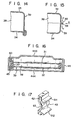
- FIG. 15 Another example is shown in Fig. 15.
- the outer peripheral portions of the first and second diaphragms 33 and 34 are bent so as to have flanges 58 and 59, as shown. In coupling those diaphragms, these flanges are laid one on top the other.
- the superposed flanges are made into a unit by electrical spot welding in the directions Y-Y. Laser welding or argon welding may be used in the direction X.
- Fig. 16 shows another embodiment of a sound generating apparatus according to the present invention.
- the housing 44 is comprised of a main body 443 with a sound passing hole 48 at the bottom, and a cover 444, which.is set on the main body to close an opening of the main body 443.
- a projection 60 which is used as a stopper, is formed inside the main body.
- a supporting member 43 is provided for the projection 60. The supporting member 43 securely holds the ring 37 of the sounding member 39.
- FIG. 17 A typical example of the supporting member 43 thus used is illustrated in Fig. 17. As shown, the supporting member 43 is provided with a pair of legs 611 and 612 for holding the ring 37, and a hole 62 for receiving the projection 60. For holding the sounding member 39, an outwardly curved portion 63 is formed to press against the side wall. The ring 37 is stably held by the curved portion.
Landscapes
- Physics & Mathematics (AREA)
- Engineering & Computer Science (AREA)
- Acoustics & Sound (AREA)
- Multimedia (AREA)
- Piezo-Electric Transducers For Audible Bands (AREA)
Abstract
Description
- The present invention relates to a sound generating apparatus with a sounding body driven by a piezoelectric element, which is well adaptable for an alarm sounding device for use in an automobile, for example.
- In the case of an alarm sounding device, such as a horn mounted to an automobile, 100 dB or more of sound pressure is required at a
position 2 m from the horn. If the horn is constructed using a diaphragm driven by a piezoelectric element, the diameter of the diaphragm must be 90 mm or more. However, in constructing the piezoelectric element for driving the diaphragm, there is a limit to which the piezoelectric element can be uncreased. The maximum size permitted is 50 mm. - In constructing an alarm sounding device for an automobile by using a sounding body in which a piezoelectric element is attached to the diaphragm, using the second-order resonance of the diaphragm driven by a piezoelectric element has been proposed.
- In Fig. 1, there is shown an arrangement of a conventional sound generating apparatus based on such a second-order resonance. A sounding
plate 11 consists of adiaphragm 12 laminated with apiezoelectric element 13 shaped like a thin plate. The soundingplate 11 is fit to afirst housing 14 to close an opening of thefirst housing 14. More specifically, asecond housing 15 is further fit to the opening of thefirst housing 14, to firmly hold thesounding plate 11 between the first andsecond housings sound passing holes second housing 15. Thesecond housing 15 contains anair layer 17 confined therein. Vibration of the soundingplate 11 acts on theair layer 17 to generate a sound. The sound generated is radiated to the exterior through thesound passing holes - The
first housing 14 is provided at the bottom with asound drive circuit 18. A sound drive signal is supplied from thesound drive circuit 18 to thesounding plate 11, through a pair oflead wires - Fig. 2 shows a configuration of the
sound drive circuit 18. An oscillatingcircuit 21 as a signal source oscillates to produce a signal, which in turn is amplified by anamplifier circuit 22. The amplified signal is boosted by a boostingtransformer 23, and then drives a soundingdevice 24 made up of the soundingplate 11. - In designing the sound generating apparatus thus arranged, particularly in designing the sound resonance, the second resonance frequency fp of the sounding
plate 11, the diameter 2a of eachsound passing hole second housing 15, the number n of the holes, the length I of the hole, and a volume V of theair layer 17 are appropriately selected using known formulae. - The length I of the hole is determined by the thickness (2 mm) of the
second housing 15. Therefore, to obtain a satisfactorily large sound pressure, it is necessary to select relatively large areas for eachhole - In the example shown in Fig. 1, for tuning a sound frequency fp at 1550 Hz, the diameter 2a of each hole is 4.8 mm, the number of holes is 24, the volume V is 90 cc (the second housing's 15 depth h = 15 mm). In this case, the amplifying effect is approximately 8 dB.
- In the sound generating apparatus thus arranged, the frequency response is configured such that the smaller the low frequency sound pressure, which becomes the fundamental frequency, the smaller the amplifying effect. Therefore, the second-order resonance characteristic mainly contributing to the sound pressure is too sharp. The result is that the sound generated is loud, noisy, and high-pitched. Thus, the sound generating apparatus can not generate a gentle or soft sound. In this respect, the sound generating apparatus provides a poor tone.
- As a means for widening the width of the peak of the resonance, Utility Model Disclosure No. 58-40717 proposes an arrangement in which two diaphragms with different frequencies are arrayed in parallel. Such an arrangement, however, has no measure to cope with phenomena peculiar to an acoustic oscillation of low frequencies, and also no means which effectively amplifies the sound generated from a couple of sounding plates. For this reason, it was very difficult to obtain a sounding characteristic satisfactory for the alarm sounding device of the automobile with the prior sound generating apparatus.
- Accordingly, an object of the present invention is to provide a sound generating apparatus using a piezoelectric element which can provide a sound pressure high enough to drive an alarm sounding device for use with an automobile, and generate a sound, which is soft but effective for alarm sounding.
- Another object of the present invention is to provide a small sound generating apparatus with a sound amplifying effect large enough to provide adequate sound pressure.
- Another object of the present invention is to provide a high quality sound for an automobile alarm sounding device, which has good response particularly in low frequencies, and thus provides a high quality,,, tone of a sound.
- A sound generating apparatus according to the present invention has a sounding member. The sounding member includes first and second sounding plates arrayed in parallel with each other. Each sounding plate includes a diaphragm laminated with a piezoelectric element. The outer peripheral portions of the first and second sounding plates are united by a ring to form an air chamber therebetween. The sounding member is mounted to a housing such that air layers are formed on the surfaces of the first and second sounding plates, and communicate with each other at the outer periphery portions of the sounding members.
- In the sound generating apparatus thus arranged, the sounding member has a substantially and hermetically sealed air chamber formed between the first and second sounding plates. Because of this feature, it is possible to effectively increase the sound pressure level in low frequencies of 800 Hz or less. Therefore, the sound generated is relatively soft, and low-pitched, not high-pitched and noisy. Further, front and rear air chambers are formed on both sides of the sounding member, and both the chambers communicate with each other by a ring-like sound path. This feature increases the sound pressure level in high frequencies of 800 Hz or more. Thus, the sound generating apparatus has an increased pressure level in both high and low frequencies. Particularly, a sound pressure increase in low frequencies, the realization of which was difficult with the prior technique, is effectively attained. Therefore, the sound generating apparatus according to the present invention is very useful when it is applied to the alarm sounding device of an automobile.
- This invention can be more fully understood from the following detailed description when taken in conjunction with the accompanying drawings, in which:
- Fig. 1 is a cross-sectional view of a conventional sound generating apparatus;
- Fig. 2 shows a configuration of a drive circuit of the sound generating apparatus of Fig. 1;
- Fig. 3 is a cross-sectional view of a sound generating apparatus which is a first embodiment of the present invention;
- Fig. 4 is a front view of the sound generating apparatus of Fig. 3 along line IV - IV;
- Fig. 5 shows curves explaining the amplifying effect in the air chamber of the Fig. 3 embodiment;
- Fig. 6 is a diagram illustrating the resonance mode of the sound generating apparatus;
- Fig. 7 shows curves illustrating the resonance amplifying effect of the sound generating apparatus;
- Fig. 8 shows curves comparing frequency responses of the first embodiment and the conventional sound generating apparatus;
- Figs. 9 to 12 respectively are cross-sectional views of the second to fifth embodiments of the present invention;
- Fig. 13 shows another configuration of the electrode arrangement for a piezoelectric element;
- Figs. 14 and 15 are a sectional view of a sounding member comprising first and second diaphragms, and a sectional view of another sounding member also comprising first and second diaphragms;
- Fig. 16 is a cross-sectional view of a sixth embodiment of a sound generating apparatus according to the present invention; and
- Fig. 17 shows an example of a supporting member used in the Fig. 16 embodiment.
- In a first embodiment of a sound generating apparatus shown in Figs. 3 and 4, first and
second sounding plates second sounding plates metal diaphragms - The
piezoelectric elements diaphragm 33 is made of KOVAR (trade name standing for a high nickel alloy made by Nihon Kougyo Co.). Thediaphragm 34 is made of brass. Thediaphragms - The peripheral portions of the first and second sounding
plates ring 37 made of synthetic resin. Anair chamber 38 is defined by the first and second soundingplates ring 37. The soundingplates air chamber 38, make up a soundingmember 39. - Pairs of
lead wires plates drive circuit 42. The pair oflead wires 401 and 402 connected to the first and second soundingplate 31 are set in and guided by grooves (not shown) of thering 37 into thedrive circuit 42 portion. - The
ring 37 is supported by supportingmembers 431 to 434 of four and made of rubber. The supportingmembers 431 to 434 are buried in depressions on the periphery of thering 37. The depressions on the periphery of thering 37. The supportingmembers 431 to 434 are mounted to the inner wall of ahousing 44 so as to permit the soundingmember 39 to be resiliently supported in thehousing 44. - The
housing 44 is composed of afirst housing 441 as a main frame and asecond housing 442 which, together with the sound generating apparatus assembly, is fitted into the opening of thefirst housing 441 to close the opening. More specifically, the supportingmembers 431 to 434 are fitted into four depressions at the opening of thefirst housing 441, and firmly held by thesecond housing 442. - The
ring 37 forming the soundingmember 39 is 93 mm in the outer diameter. The inner diameter of thehousing 44 is 100 mm. Asound path 45 with a height h and width y is formed around the entire periphery of thering 37. Afront air layer 46 with a thickness ha of 11 mm is formed between the first and second soundingplate 31, and thesecond housing 442. Arear air layer 47 with a thickness R of 5 mm is formed between the soundingplate 32 and thefirst housing 441. - Sound passing holes of 48, for example, are formed on the bottom side of the
second housing 442 serving as the front side of the sound generating apparatus. These holes each have a 4.8 mm diameter and are distributed on the peripheral portion of the bottom side. - In the sound generating apparatus, thus arranged to create a low frequency resonance, it is known that the vibrating portion has a large diameter and thickness, while its peripheral portion is fixed. In the case of a sound generating apparatus having the dimensions as mentioned above, the first-order resonance frequencies of the first and second sounding
plates - The inventors have found the following facts in relation to such a sound generating apparatus. The
air chamber 38 defined by the first and second soundingplates - Let us consider the amplifying effect of the first-order resonance sound pressure. An acoustic wave radiated from the rear side of the first sounding
plate 31, and which is out of phase with respect to that from the obverse side, is cut by the second soundingplate 32. The second sounding plate.32 also prevents acoustic wave cancellation resulting from diffraction of the acoustic wave. - It is assumed that the second sounding
plate 32 is not used in the apparatus under discussion. The antiphase acoustic wave passes through thesound path 45, and interferes with the sound radiated from the obverse side of the 'first soundingplate 31, and is thereby neutralized. - Further, since the
air chamber 38 is hermetically sealed, the oscillation occuring therein is amplified due to interaction with the interior air, resulting in amplification of the acoustic energy. - The first sounding
plate 31 also acts on the second soundingplate 32 in a similar way. Therefore, the effect of theair chamber 38 is as illustrated in Fig. 5. - In Fig. 5, curves A and B show the oscillating frequency characteristics for a sinusoidal wave input when only the first or second sounding
plate plates member 39 taken out of thehousing 44. - In the sound generating apparatus as mentioned above, the
air chamber 38 sandwiched by the first and second soundingplates plates - Let us consider now the second-order resonance operation. The second-order resonance frequencies of the first and second sounding
plates sound path 45 and therear air chamber 47. The resonance frequency is about 1,400 Hz, which is approximate to the mid frequency between the second-order frequencies of the first and second soundingplates sound path 45 are appropriately selected to tune the resonance frequency to such a frequency. - Therefore, simply by providing a
sound path 45, whose length corresponds to the width of thering 37, a satisfactory second-order amplifying effect can be obtained even if the volume V (corresponding to ha) of thefront air chamber 46 is small. - The resonance mode of the sound generating apparatus was analyzed by a finite element simulation technique. The result of the analysis is shown in Fig. 6. In the figure, the size of each circle indicates the magnitude of the sound pressure (resonance mode) at the center of each circle. As shown, the
front air layer 46 also resonates with therear air layer 47 through the interaction therebetween (mutual excitation). Accordingly, the second-order resonating sound pressure of the first soundingplate 31 is amplified by this mutual excitation. - In the present embodiment, the
front air layer 46 is thicker than therear air layer 47. Thesound passing holes second housing 442 as possible. Such an arrangement of the sound generating apparatus is desirable for enhancing the amplifying effect of the soundingplate 31. - In Fig. 7, which shows the resonance amplifying effect of the sound generating'apparatus in the above-mentioned embodiment, a continuous curve indicates the resonance amplifying effect of the present embodiment, while a broken curve indicates the resonance amplifying effect when the
housing 44 is removed. Each of the curves shown in Fig. 7 correspond to the curve as indicated by the continuous line in Fig. 5. The curves plotted in Fig. 7 are based on the frequency data for a sinusoidal wave input. As shown, because of the presence of thehousing 44, the resonance sound pressures of the first and second soundingplates - In the prior art sound generating apparatus as shown in Fig. 1, a resonance chamber is provided for a single sounding plate. Therefore, if two sounding plates are used, two resonance chambers are needed, thereby doubling the size of the sound generating apparatus.
- On the other hand, in the sound generating apparatus according to the present invention, the total thickness of the front and rear air layers 46 and 47 is 15 mm. Thus, with the thickness of the air layer comparable with that when a single sounding plate is used, the acoustic waves generated by the two sounding
plates - The supporting
members member 39 will be described. In the first-order resonance mode of each of the first and second soundingplates member 39, no oscillation node resides on the peripheral portion thereof, and the vibration of thering 37 is large. Therefore, if thering 37 is completely fixed, the vibration at the supporting portion is restrained, so that a trembling sound is generated thereat. To avoid such a sound, the supportingmembers - Fig. 8 comparatively shows frequency responses of the present embodiment and of the prior art sound generating apparatus. In the figure, a continuous line indicates the frequency response of the present embodiment shown in Fig. 3, and a broken line, the frequency response of the prior art of Fig. 1.
- As seen from Fig. 8, although it is comparable in size with the prior art of Fig. 1, the sound generating apparatus of Fig. 3 has good response in low frequencies which form the fundamental frequency, and a broad band width of the second-order resonance serving as a sound pressure component. For example, if the
drive circuit 42 produces an oscillating wave signal containing components of about 400 Hz, about 500 Hz, about 1200 Hz and about 1500 Hz, a soft and rich tone is generated. Such a sound is desirable for the alarm sound of an automobile. - In the above-mentioned embodiment, the supporting
members member 39 are projected from thefirst housing 441 into a part of thering 37. Alternatively, the supportingmembers member 39, it receives the entire width of thering 37, as shown in Fig. 9. In other words, thering 37 is fitted into the supportingmembers second housing 442 is tapered downwardly, to securely hold the supportingmembers - If necessary, a
hole 52 with a diameter, for example, of 1.5 mm, may be formed in the side wall of thering 37, providing the amplifying effect of theinternal air chamber 38 is not damaged. With this, it is possible to avoid a change in characteristics due to a pressure difference in theair chamber 38. Further, sound passing holes may be formed in the side wall of thehousing 44. - To obtain different resonance frequencies of the first and second sounding plates .31 and 32, the sounding
plates diaphragms - While in the above-mentioned embodiment the sounding
member 39 is made up of twoseparate diaphragms member 39 is not limited as such. For example, as shown in Fig. 11, the peripheral portions of thediaphragms diaphragms diaphragms grooves ring 37. - As for the structure of the supporting portion of the sounding
member 39, acollar flange 54 is projected into the outer periphery portion of thering 37. Further, a number of sound passing holes formed in the second housing may be replaced by slits. - In the above-mentioned embodiments, as for the first and second sounding
plates plates member 39, may take a bimorph structure. This is realized by an embodiment shown in Fig. 12. As shown, a pair ofpiezoelectric elements first diaphragm 33. Another pair of piezoelectric elements are attached to both sides of thesecond diaphragm 34. - In this case, these pairs of
piezoelectric elements diaphragms - When employing such an arrangement, an
electrode 55 is formed on the surface of the piezoelectric element, as shown in Fig. 13, and asubelectrode 56 divided from theelectrode 55, is formed on the piezoelectric element. By using these three electrodes, theelectrodes electrode 57 on the diaphragm, a self-excitation drive-signal generating means may be formed. - In the sound generating apparatus shown in Fig. 3, the
ring 37 is used for mounting the first and second soundingplates second diaphragms - To be more specific, as shown in Fig. 14, one of the
diaphragms diaphragm 33 is in contact with that of theother diaphragm 34, and these peripheral portions are rolled for caulking, as shown in Fig. 14. In this way, anair chamber 38 is formed between thediaphragms second diaphragms flanges - Fig. 16 shows another embodiment of a sound generating apparatus according to the present invention. As shown, the
housing 44 is comprised of amain body 443 with a sound passing hole 48 at the bottom, and acover 444, which.is set on the main body to close an opening of themain body 443. Aprojection 60, which is used as a stopper, is formed inside the main body. A supportingmember 43 is provided for theprojection 60. The supportingmember 43 securely holds thering 37 of the soundingmember 39. - A typical example of the supporting
member 43 thus used is illustrated in Fig. 17. As shown, the supportingmember 43 is provided with a pair oflegs ring 37, and ahole 62 for receiving theprojection 60. For holding the soundingmember 39, an outwardlycurved portion 63 is formed to press against the side wall. Thering 37 is stably held by the curved portion.
Claims (18)
Applications Claiming Priority (2)
| Application Number | Priority Date | Filing Date | Title |
|---|---|---|---|
| JP58242194A JPS60134700A (en) | 1983-12-23 | 1983-12-23 | Sound producing device |
| JP242194/83 | 1983-12-23 |
Publications (3)
| Publication Number | Publication Date |
|---|---|
| EP0146933A2 true EP0146933A2 (en) | 1985-07-03 |
| EP0146933A3 EP0146933A3 (en) | 1986-10-01 |
| EP0146933B1 EP0146933B1 (en) | 1990-02-28 |
Family
ID=17085683
Family Applications (1)
| Application Number | Title | Priority Date | Filing Date |
|---|---|---|---|
| EP84115942A Expired EP0146933B1 (en) | 1983-12-23 | 1984-12-20 | Sound generating apparatus |
Country Status (4)
| Country | Link |
|---|---|
| US (1) | US4700177A (en) |
| EP (1) | EP0146933B1 (en) |
| JP (1) | JPS60134700A (en) |
| DE (1) | DE3481458D1 (en) |
Cited By (4)
| Publication number | Priority date | Publication date | Assignee | Title |
|---|---|---|---|---|
| GB2205159A (en) * | 1987-05-27 | 1988-11-30 | Diehl Gmbh & Co | An electronic acoustic signal transmitter mounted on a printed circuit board |
| WO1996031869A1 (en) * | 1995-04-05 | 1996-10-10 | Societe De Composants Electriques | Piezoelectric horn, particularly for vehicles |
| GB2306075A (en) * | 1995-08-11 | 1997-04-23 | Ind Tech Res Inst | Piezoelectric full-range loudspeaker |
| GB2348078A (en) * | 1999-04-26 | 2000-09-20 | Inst Francais Du Petrole | Hydrophone for acoustic or seismic wave reception |
Families Citing this family (36)
| Publication number | Priority date | Publication date | Assignee | Title |
|---|---|---|---|---|
| US4796009A (en) * | 1987-03-09 | 1989-01-03 | Alerting Communicators Of America | Electronic warning apparatus |
| US5049853A (en) * | 1987-10-19 | 1991-09-17 | Sparton Corporation | Electric horn with solid state driver |
| US5160913A (en) * | 1987-10-19 | 1992-11-03 | Sparton Corporation | Electric horn with solid state driver |
| JP2567148B2 (en) * | 1990-11-20 | 1996-12-25 | 日本電気株式会社 | Wireless selective call receiver |
| US5373281A (en) * | 1991-08-15 | 1994-12-13 | Nartron Corporation | Failsafe module |
| US5363452A (en) * | 1992-05-19 | 1994-11-08 | Shure Brothers, Inc. | Microphone for use in a vibrating environment |
| US5386479A (en) * | 1992-11-23 | 1995-01-31 | Hersh; Alan S. | Piezoelectric sound sources |
| US5391053A (en) * | 1993-11-01 | 1995-02-21 | General Electric Company | Active noise control using noise source having adaptive resonant frequency tuning through variable panel loading |
| US5415522A (en) * | 1993-11-01 | 1995-05-16 | General Electric Company | Active noise control using noise source having adaptive resonant frequency tuning through stress variation |
| US5382134A (en) * | 1993-11-01 | 1995-01-17 | General Electric Company | Active noise control using noise source having adaptive resonant frequency tuning through stiffness variation |
| US5423658A (en) * | 1993-11-01 | 1995-06-13 | General Electric Company | Active noise control using noise source having adaptive resonant frequency tuning through variable ring loading |
| BR9506242A (en) * | 1994-05-20 | 1997-08-12 | Shinsei Corp | Sound generating device |
| US5458222A (en) * | 1994-12-05 | 1995-10-17 | General Electric Company | Active vibration control of structures undergoing bending vibrations |
| US5558298A (en) * | 1994-12-05 | 1996-09-24 | General Electric Company | Active noise control of aircraft engine discrete tonal noise |
| US5590849A (en) * | 1994-12-19 | 1997-01-07 | General Electric Company | Active noise control using an array of plate radiators and acoustic resonators |
| US5618010A (en) * | 1994-12-19 | 1997-04-08 | General Electric Company | Active noise control using a tunable plate radiator |
| US5584447A (en) * | 1994-12-19 | 1996-12-17 | General Electric Company | Noise control using a plate radiator and an acoustic resonator |
| US5901231A (en) * | 1995-09-25 | 1999-05-04 | Noise Cancellation Technologies, Inc. | Piezo speaker for improved passenger cabin audio systems |
| US5749433A (en) * | 1996-02-13 | 1998-05-12 | Jackson; Michael | Massline loudspeaker enclosure |
| USH1875H (en) * | 1996-07-22 | 2000-10-03 | Microtronic A/S | Electroacoustic transducer |
| DE19935768C2 (en) * | 1999-07-23 | 2003-10-09 | Auergesellschaft Gmbh | Piezoelectric acoustic alarm |
| US6657364B1 (en) * | 1999-10-01 | 2003-12-02 | Ngk Insulators, Ltd. | Piezoelectric/electrostrictive device |
| DE60035932T2 (en) * | 1999-10-01 | 2008-05-15 | Ngk Insulators, Ltd., Nagoya | Piezoelectric / electrostrictive device and its manufacturing method |
| US6166623A (en) * | 1999-12-22 | 2000-12-26 | Electronics Controls Company | Modular alarm assembly |
| US6987445B1 (en) * | 2000-09-22 | 2006-01-17 | Mallory Sonalert Products, Inc. | Water resistant audible signal |
| JP4033643B2 (en) * | 2001-06-18 | 2008-01-16 | 日本碍子株式会社 | Piezoelectric / electrostrictive device and manufacturing method thereof |
| WO2009098888A1 (en) * | 2008-02-08 | 2009-08-13 | Temco Japan Co., Ltd. | Vibration pickup microphone |
| US8111832B2 (en) * | 2008-04-16 | 2012-02-07 | The United States Of America As Represented By The Administrator Of The National Aeronautics And Space Administration | Method of adjusting acoustic impedances for impedance-tunable acoustic segments |
| JP5594435B2 (en) * | 2011-08-03 | 2014-09-24 | 株式会社村田製作所 | Ultrasonic transducer |
| US20130039522A1 (en) * | 2011-08-11 | 2013-02-14 | Versonix Corporation | Flat speaker device and method of fabricating the same |
| US9107005B2 (en) | 2012-02-15 | 2015-08-11 | Panasonic Intellectual Property Management Co., Ltd. | Speaker |
| US9179220B2 (en) | 2012-07-10 | 2015-11-03 | Google Inc. | Life safety device with folded resonant cavity for low frequency alarm tones |
| WO2014174729A1 (en) * | 2013-04-24 | 2014-10-30 | 株式会社村田製作所 | Ultrasound emission device |
| US8810426B1 (en) * | 2013-04-28 | 2014-08-19 | Gary Jay Morris | Life safety device with compact circumferential acoustic resonator |
| CN106932817B (en) * | 2017-01-23 | 2018-11-30 | 中国人民解放军海军工程大学 | A kind of comprehensive detection ground sound-underwater sound signal piezoelectric transducer |
| KR102002805B1 (en) * | 2018-02-02 | 2019-07-23 | (주)와이솔 | Housing assembly comprising piezoelectric speaker unit to be installed on mobile terminal |
Citations (5)
| Publication number | Priority date | Publication date | Assignee | Title |
|---|---|---|---|---|
| FR618595A (en) * | 1925-11-16 | 1927-03-11 | Thomson Houston Comp Francaise | Improvements to sound reproduction systems |
| US2126436A (en) * | 1935-01-07 | 1938-08-09 | Brush Deveiepment Company | Acoustical apparatus |
| FR1578513A (en) * | 1967-08-28 | 1969-08-14 | ||
| US3970878A (en) * | 1975-03-31 | 1976-07-20 | Teledyne Exploration Company | Piezoelectric transducer unit and hydrophone assembly |
| DE2738773A1 (en) * | 1976-09-01 | 1978-03-09 | Seiko Instr & Electronics | ELECTROACOUSTIC CONVERTER |
Family Cites Families (17)
| Publication number | Priority date | Publication date | Assignee | Title |
|---|---|---|---|---|
| US2202467A (en) * | 1936-07-23 | 1940-05-28 | Bell Telephone Labor Inc | Artificial larynx |
| US3055451A (en) * | 1958-10-16 | 1962-09-25 | Kenney George Robert | Speaker cabinet |
| US3721840A (en) * | 1971-09-14 | 1973-03-20 | Nittan Co Ltd | Sound generator |
| GB1412457A (en) * | 1971-12-27 | 1975-11-05 | Sumitomo Electric Industries | Sound generator comprising a piezoelectric acoustic device |
| US3970879A (en) * | 1971-12-29 | 1976-07-20 | Sumitomo Electric Industries, Ltd. | Piezoelectric acoustic device |
| JPS5257232A (en) * | 1975-11-05 | 1977-05-11 | Catalysts & Chem Ind Co | Method of manufacturing inorganic fibrous molded products |
| JPS538594A (en) * | 1976-07-13 | 1978-01-26 | Seiko Instr & Electronics Ltd | Electronic buzzer |
| CA1113288A (en) * | 1977-11-09 | 1981-12-01 | Mallory (P. R.) & Co. Inc. | Modular piezoelectric transducer component for audible signaling |
| JPS5840717Y2 (en) * | 1979-03-09 | 1983-09-13 | 富士電気化学株式会社 | piezoelectric sounding body |
| US4374377A (en) * | 1979-12-12 | 1983-02-15 | Sumitomo Electric Industries, Ltd. | Piezoelectric audio transducer |
| JPS577099U (en) * | 1980-02-28 | 1982-01-14 | ||
| DE3138068A1 (en) * | 1980-11-10 | 1982-07-08 | Marukokeihouki Co. Ltd., Nagano | PIEZOELECTRIC MULTI-FREQUENCY SOUND GENERATING DEVICE |
| JPS57113697A (en) * | 1981-01-05 | 1982-07-15 | Murata Mfg Co Ltd | Piezoelectric type speaker |
| US4409588A (en) * | 1981-03-10 | 1983-10-11 | Pickering & Company, Inc. | Miniature sounder with multi-part tuned cavities |
| CH642504A5 (en) * | 1981-06-01 | 1984-04-13 | Asulab Sa | Hybrid electroacoustic transducer |
| JPS5840717A (en) * | 1981-09-02 | 1983-03-09 | 三菱電機株式会社 | Gas breaker |
| US4641054A (en) * | 1984-08-09 | 1987-02-03 | Nippon Ceramic Company, Limited | Piezoelectric electro-acoustic transducer |
-
1983
- 1983-12-23 JP JP58242194A patent/JPS60134700A/en active Granted
-
1984
- 1984-12-17 US US06/682,755 patent/US4700177A/en not_active Expired - Fee Related
- 1984-12-20 DE DE8484115942T patent/DE3481458D1/en not_active Expired - Lifetime
- 1984-12-20 EP EP84115942A patent/EP0146933B1/en not_active Expired
Patent Citations (5)
| Publication number | Priority date | Publication date | Assignee | Title |
|---|---|---|---|---|
| FR618595A (en) * | 1925-11-16 | 1927-03-11 | Thomson Houston Comp Francaise | Improvements to sound reproduction systems |
| US2126436A (en) * | 1935-01-07 | 1938-08-09 | Brush Deveiepment Company | Acoustical apparatus |
| FR1578513A (en) * | 1967-08-28 | 1969-08-14 | ||
| US3970878A (en) * | 1975-03-31 | 1976-07-20 | Teledyne Exploration Company | Piezoelectric transducer unit and hydrophone assembly |
| DE2738773A1 (en) * | 1976-09-01 | 1978-03-09 | Seiko Instr & Electronics | ELECTROACOUSTIC CONVERTER |
Cited By (8)
| Publication number | Priority date | Publication date | Assignee | Title |
|---|---|---|---|---|
| GB2205159A (en) * | 1987-05-27 | 1988-11-30 | Diehl Gmbh & Co | An electronic acoustic signal transmitter mounted on a printed circuit board |
| GB2205159B (en) * | 1987-05-27 | 1991-07-03 | Diehl Gmbh & Co | An electronic acoustic signal transmitter |
| WO1996031869A1 (en) * | 1995-04-05 | 1996-10-10 | Societe De Composants Electriques | Piezoelectric horn, particularly for vehicles |
| FR2732805A1 (en) * | 1995-04-05 | 1996-10-11 | Klaxon Sa | PIEZOELECTRIC SOUND WARNING DEVICE, PARTICULARLY FOR VEHICLE EQUIPMENT |
| US6166624A (en) * | 1995-04-05 | 2000-12-26 | Societe De Composants Electriques | Piezoelectric horn, particularly for vehicles |
| GB2306075A (en) * | 1995-08-11 | 1997-04-23 | Ind Tech Res Inst | Piezoelectric full-range loudspeaker |
| GB2348078A (en) * | 1999-04-26 | 2000-09-20 | Inst Francais Du Petrole | Hydrophone for acoustic or seismic wave reception |
| GB2348078B (en) * | 1999-04-26 | 2003-07-30 | Inst Francais Du Petrole | Hydrophone for accoustic or seismic wave reception |
Also Published As
| Publication number | Publication date |
|---|---|
| JPS60134700A (en) | 1985-07-17 |
| EP0146933A3 (en) | 1986-10-01 |
| US4700177A (en) | 1987-10-13 |
| DE3481458D1 (en) | 1990-04-05 |
| JPH0535439B2 (en) | 1993-05-26 |
| EP0146933B1 (en) | 1990-02-28 |
Similar Documents
| Publication | Publication Date | Title |
|---|---|---|
| EP0146933B1 (en) | Sound generating apparatus | |
| US4504703A (en) | Electro-acoustic transducer | |
| US6606389B1 (en) | Piezoelectric film sonic emitter | |
| US7668323B2 (en) | Electrostatic ultrasonic transducer and ultrasonic speaker | |
| US5751827A (en) | Piezoelectric speaker | |
| JP3123431B2 (en) | Piezo speaker | |
| MXPA97000089A (en) | Systems of acceleration sensitivity microphone in site reduc | |
| JPS63503505A (en) | Acoustic transducer with improved electrode spacing | |
| JP3395672B2 (en) | Piezoelectric electroacoustic transducer | |
| US4027115A (en) | Electroacoustic sound generator | |
| US4638205A (en) | Piezo-electric transducer | |
| US4321699A (en) | Wrist watch with alarm | |
| JP2001036993A (en) | Piezoelectric electro-acoustic transducer | |
| GB2145905A (en) | Audible warning device | |
| CN217088147U (en) | Loudspeaker | |
| JPS6161759B2 (en) | ||
| JPS6360400B2 (en) | ||
| JPH0332958B2 (en) | ||
| JP2003508937A (en) | Bass diaphragm speaker | |
| JP2568674Y2 (en) | Sound equipment | |
| JPH0554320B2 (en) | ||
| JPS6031359Y2 (en) | electroacoustic transducer | |
| JPH114497A (en) | Piezoelectric receiver | |
| JP2000059879A (en) | Speaker device | |
| CN114786101A (en) | Loudspeaker |
Legal Events
| Date | Code | Title | Description |
|---|---|---|---|
| PUAI | Public reference made under article 153(3) epc to a published international application that has entered the european phase |
Free format text: ORIGINAL CODE: 0009012 |
|
| AK | Designated contracting states |
Designated state(s): DE FR GB |
|
| PUAL | Search report despatched |
Free format text: ORIGINAL CODE: 0009013 |
|
| AK | Designated contracting states |
Kind code of ref document: A3 Designated state(s): DE FR GB |
|
| 17P | Request for examination filed |
Effective date: 19861107 |
|
| 17Q | First examination report despatched |
Effective date: 19880822 |
|
| GRAA | (expected) grant |
Free format text: ORIGINAL CODE: 0009210 |
|
| AK | Designated contracting states |
Kind code of ref document: B1 Designated state(s): DE FR GB |
|
| REF | Corresponds to: |
Ref document number: 3481458 Country of ref document: DE Date of ref document: 19900405 |
|
| ET | Fr: translation filed | ||
| REG | Reference to a national code |
Ref country code: GB Ref legal event code: 746 |
|
| PLBE | No opposition filed within time limit |
Free format text: ORIGINAL CODE: 0009261 |
|
| STAA | Information on the status of an ep patent application or granted ep patent |
Free format text: STATUS: NO OPPOSITION FILED WITHIN TIME LIMIT |
|
| 26N | No opposition filed | ||
| REG | Reference to a national code |
Ref country code: FR Ref legal event code: DL |
|
| PGFP | Annual fee paid to national office [announced via postgrant information from national office to epo] |
Ref country code: FR Payment date: 19981209 Year of fee payment: 15 |
|
| PGFP | Annual fee paid to national office [announced via postgrant information from national office to epo] |
Ref country code: GB Payment date: 19981224 Year of fee payment: 15 |
|
| PGFP | Annual fee paid to national office [announced via postgrant information from national office to epo] |
Ref country code: DE Payment date: 19981229 Year of fee payment: 15 |
|
| PG25 | Lapsed in a contracting state [announced via postgrant information from national office to epo] |
Ref country code: GB Free format text: LAPSE BECAUSE OF NON-PAYMENT OF DUE FEES Effective date: 19991220 |
|
| GBPC | Gb: european patent ceased through non-payment of renewal fee |
Effective date: 19991220 |
|
| PG25 | Lapsed in a contracting state [announced via postgrant information from national office to epo] |
Ref country code: FR Free format text: LAPSE BECAUSE OF NON-PAYMENT OF DUE FEES Effective date: 20000831 |
|
| PG25 | Lapsed in a contracting state [announced via postgrant information from national office to epo] |
Ref country code: DE Free format text: LAPSE BECAUSE OF NON-PAYMENT OF DUE FEES Effective date: 20001003 |
|
| REG | Reference to a national code |
Ref country code: FR Ref legal event code: ST |