EP0145997B2 - Reproduction errors compensation device for electroacoustic transducers - Google Patents
Reproduction errors compensation device for electroacoustic transducers Download PDFInfo
- Publication number
- EP0145997B2 EP0145997B2 EP84114089A EP84114089A EP0145997B2 EP 0145997 B2 EP0145997 B2 EP 0145997B2 EP 84114089 A EP84114089 A EP 84114089A EP 84114089 A EP84114089 A EP 84114089A EP 0145997 B2 EP0145997 B2 EP 0145997B2
- Authority
- EP
- European Patent Office
- Prior art keywords
- signals
- circuit
- transducer
- digital
- microcomputer
- Prior art date
- Legal status (The legal status is an assumption and is not a legal conclusion. Google has not performed a legal analysis and makes no representation as to the accuracy of the status listed.)
- Expired - Lifetime
Links
Images


Classifications
-
- H—ELECTRICITY
- H04—ELECTRIC COMMUNICATION TECHNIQUE
- H04R—LOUDSPEAKERS, MICROPHONES, GRAMOPHONE PICK-UPS OR LIKE ACOUSTIC ELECTROMECHANICAL TRANSDUCERS; DEAF-AID SETS; PUBLIC ADDRESS SYSTEMS
- H04R3/00—Circuits for transducers, loudspeakers or microphones
- H04R3/04—Circuits for transducers, loudspeakers or microphones for correcting frequency response
Definitions
- the invention relates to a device according to the preamble of claim 1.
- Electrodynamic pickup systems are mechanical vibration systems, which are characterized by their own values such as spring constant, mass and damping. Speakers, i.e. Wanders that receive electrical signals and emit acoustic signals are e.g. with the help of a voice coil excited and damped vibrations. Conversely, microphones are transducers that convert acoustic signals into electrical signals. With electrodynamic microphones, this is also done with the help of a voice coil attached to a membrane. Electrodynamic pickup systems also pick up mechanical vibrations and generate electrical signals using voice coils. For this reason, there are no fundamental differences between electrodynamic microphones and electrodynamic pickup systems.
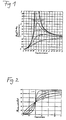
- amplitude frequency response is e.g. the non-linear course with resonance points and the low efficiency at the upper and lower end of the transmission range.
- a conventional, softly suspended bass loudspeaker of approx. 30 cm ⁇ at 20 Hz built into a closed housing shows only a low sound pressure effect with amplitude values that are too low, but achieves over-loudness with its resonance frequency in the range of approx. 40 - 80 Hz too large amplitude values and decreases again against high frequencies effectiveness in sound transmission due to too small amplitude values.
- the amplitude ratio is clearly shown by the frequency ratio related to the resonance frequency in FIG. 1 with a different damping factor ⁇ . This representation is known prior art and is not further explained here.
- the membrane begins to move in the same direction with vibration pulses above and below the resonance frequency, but only reaches low amplitude values in the case of pulses near and below the resonance frequency, especially during the first half of the oscillation period, since the phase shift occurs during the transient process . It is only when the phase shift corresponding to the frequency has taken place that the amplitude values corresponding to the exciting signal are reached, albeit out of phase.
- Impulse-like vibrations such as striking a guitar string, striking a note on the piano or hitting a drum, show the maximum amplitude when struck the first time and then vibrate in the torn tone frequency.
- a loudspeaker system or microphone which is operated in the range of its resonance frequency, must first settle slowly with such pulses until it has the phase position corresponding to the frequency, and only then, depending on the quality, usually reaches the maximum amplitude after one or two full oscillation periods.
- the transducer resonates at least for a period of time predetermined by the phase shift. In the subsequent decay process, the more or less well damped natural or resonant frequency of the transducer can be seen.
- the human ear only evaluates the volume according to the amplitude of pure sine tones. Mixtures of sounds that always make up music are evaluated using the envelope.
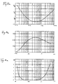
- FIG. 3 shows the known arrangement of a loudspeaker with a sensor for the membrane movement.
- the movement of the membrane is scanned capacitively, inductively, piezoelectrically or optically and the electrical actual value signals generated in this way are compared with the setpoint signals.
- the readjustment is carried out via a differential amplifier.
- the capacitive motion sensors record not only the entire diaphragm movement but also all partial vibrations of the diaphragm, the inductive sensors move in the strongly changing magnetic field, which is influenced by the excitation winding through which current flows. They therefore only allow a rough detection of errors.
- the piezo transducers are relatively heavy and, due to their own weight, increase the error to be corrected. They cannot be used for the mid and high range.
- the optical pickups with their own control electronics are uneconomically expensive.
- the control loop would start to oscillate if the loop gain was high. To prevent this, the loop gain must be set to small values, e.g. 20, can be reduced, which greatly affects the effectiveness of the feedback.
- FIG. 5a An equivalent circuit for the actual loudspeaker was used to try to get a better correction signal.
- the equivalent circuit is used for this purpose in a feedback circuit according to FIG. 5a.
- the disadvantage of this circuit is that replacement circuits constructed discretely with coils, capacitors and resistors, as well as the electrodynamic converters themselves, already show considerable differences in the assembled end product, even with small component and manufacturing tolerances. Such an equivalent circuit constructed with discrete components is therefore difficult to match to the actual loudspeaker conditions, cannot be tuned and is expensive. 4 may also be arranged inversely in series with the loudspeaker (FIG. 5b), which is known from US Pat. No. 3,988,541.
- a compensation device of the type mentioned for playback errors of an electroacoustic transducer which is used to straighten the sound pressure curve at the upper and lower end of the transmission range of electrodynamic loudspeakers.
- the circuit arrangement consists of active components.
- the individual circuit sections or filters are effective for the separate compensation of errors in different frequency ranges, i.e. Adjustment measures in a circuit section only affect the corresponding frequency range and do not affect the entire transmission range of the converter.
- the known circuit arrangement cannot fully take into account or compensate for the complex transmission behavior of the converter and its transmission errors. An approximate linearization of the frequency response or sound pressure curve is provided. After the compensation has been carried out, there are still significant phase errors.
- Circuits to influence the sound pressure curve of loudspeakers in any way are equalizers. These filter circuits are suitable for linearizing the sound pressure curve or for straightening the amplitude frequency response.
- graphic equalizers the transmission frequency range from 20 to 20,000 Hz is divided into predetermined, frequency-limited sub-ranges, in which corrections are carried out in each case. A setting for other correction areas is not possible.
- the so-called parametric equalizers of which US Pat. No. 4,052,560 describes a circuit arrangement, also enable the subsequent adjustment of special partial frequency ranges and the filter characteristic, as a result of which adaptation to any correction points can take place.
- the phase frequency response of the converter is generally not improved, but often the phase error of the equalizer circuits is superimposed on it.
- the parametric equalizers also allow for very limited improvements in the phase frequency response.
- a major advantage of the equalizer is the limitation of the setting options of its active filters to relatively small sub-frequency ranges, which makes setting any, even linear, sound pressure curves relatively easy and clear.
- phase frequency response is influenced by the approximate linearization of the sound pressure curve, but is not properly compensated for.
- the correction in each case in partial frequency ranges does not take sufficient account of the complex overall relationship of the electrodynamic converter. Instead of compensating the phase errors, these are at most brought to smaller values.
- Bass equalization in the lower frequency range is described in numerous references.
- the known circuits often do not record the entire mechanical vibration system of the electrodynamic loudspeaker in its full transmission range.
- these circuits are often not assigned to a single electrodynamic loudspeaker, but they are upstream of multipath loudspeakers which contain high, medium and bass loudspeakers and a crossover network.
- crossovers themselves cause phase errors and the phase errors of two sub-frequency loudspeakers produce further errors when they are superimposed, such measures can actually only straighten the sound pressure curve; the compensation of the phase errors is not possible.
- the invention has for its object to provide a device for compensating playback errors of an electroacoustic, in particular working according to the electrodynamic principle, by which the signals occurring in the electrical section of the transmission path are changed so that the system-related errors are at least largely compensated.
- the compensation devices should consist of inexpensive active electronic components and setting elements and should be easily and individually adjustable in a wide range to different converter types.
- the advantages of the compensation circuit are even clearer if one takes into account that the easy adjustability is just as easily possible not only on speakers of the same series type, but even on speakers as different as woofers, mid-range speakers or tweeters.
- the material cost of the active electronic components and the adjustability of the actuators result in a great cost advantage.
- the compensation circuit can be used universally, that is to say for all electrodynamic loudspeaker systems and electrodynamic headphones as well as for all electrodynamic microphones and electrodynamic pickups, results in a large field of application with a cost advantage and manufacturing advantage that increase again due to mass or series production.
- the crossover is constructed according to DE-C-33 04 402 and thus ensures correct settling and all phases in all frequency ranges, the transient response of the bass, mid-range and tweeters results in Sound bursts from sound mixtures, as they are common in music, for example when striking the piano, guitar and drum, there are no phase shifts and no sound changes over the entire reusable loudspeaker box due to overlapping frequency ranges that have experienced different phase shifts.
- the membranes of the tweeter, midrange and bass loudspeaker remain in the same phase with all suggestions, whether through impulses or through long-lasting tones.
- Another advantage is that standard loudspeaker specimens can be used in loudspeaker construction. You do not need any special designs, such as with sensors for readjustment or expensive, narrow-tolerance components and special manufacturing processes to maintain certain parameters.
- Another advantage is that the electrical characteristics of the compensation circuit do not change during operation, as happens with coils and capacitors due to heating during operation. It is also advantageous that non-linearities due to components such as e.g. in the coil due to hysteresis, saturation and eddy current, do not occur in the adjustable compensation circuit with operational amplifiers.
- the easy and universal tunability is also advantageous if a converter is destroyed and has to be replaced.
- the compensation circuit provides a high utility value for repairs.
- a significant advantage of the compensation circuit is also to be emphasized that it can be implemented extremely inexpensively by only a few active components.
- the small space requirement of the compensation circuit which is easily conceivable in the size of an operational amplifier customary today, compared to the large passive components of a loudspeaker equivalent circuit, e.g. when used in the bass range.
- FIG. 7 shows a known loudspeaker equivalent circuit diagram with a differentiating stage connected downstream.
- the values for the example with the bass speaker are determined dynamically on the bass, ie the complex input impedance is measured at different frequencies and the component values for the known equivalent circuit are mathematically calculated from this.
- the behavior of the equivalent circuit corresponds exactly to that of the loudspeaker itself.
- R S 6.8 ⁇
- R1 40 ⁇
- the voltage U 1 At the input terminals of the speaker or its exact electrical replication by the equivalent circuit, the voltage U 1 is applied, the voltage U 2 can be tapped at the output terminals.
- the damping function results from the ratio U 1 / U 2, from the phase shift from U i to U2 the phase angle curve.
- the general mathematical damping function for the example above is:
- the component values are standardized to simplify the calculation.
- the freely selectable reference values (index B) are chosen so that the relationships are as simple as possible.
- This damping function to be compensated for by the compensation circuit as a function of the frequency is shown in FIG. 8a for the example of the bass loudspeaker, but runs in basically the same way for all electrodynamic converters.
- the phase angle curve to be compensated for by the compensation circuit as a function of the frequency was recorded in FIG. 8b for the example of the bass loudspeaker, but this curve also runs schematically for all electrodynamic converters (see also FIG. 2).
- Simply reversing equation (3) in order to get the entire loudspeaker behavior in inverse form does not provide a solution, since this function is not stable in terms of circuitry and oscillates.
- the path to a compensation circuit is shown below which, like the equivalent circuit of the loudspeaker as an analog computer, has similarly complex cross-connections to one another, but only represents the inverse function in a sufficiently good approximation in the loudspeaker transmission range.
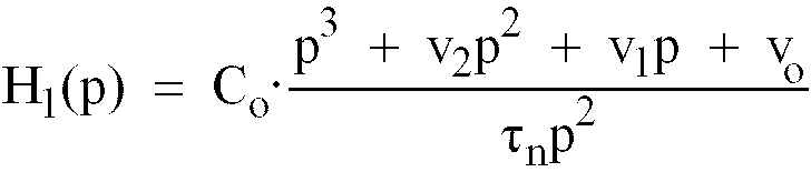
- the inverse function H (p) is applied in a general form as a polynomial in such a way that the numerator from equation (3) with the coefficients that were determined on the loudspeaker comes into the denominator of equation (4) and the new counter in equation (4) is generally applied.
- the mathematical stability criterion here requires that the degree of the numerator of the polynomial is equal to or greater than the degree of the denominator.
- the approximation process itself is carried out by suitable selection of the coefficients, which are improved as long as until the desired result is achieved.
- the coefficient improvement is always gradual and in the overall transmission system.
- the individual calculation steps can be numerical, with the help of computing computers, done with graphics computers.
- the change in the coefficient can be assessed directly in terms of the effect on the change in the curve, and the process can thereby be accelerated.
- the fine adjustment can be carried out with the oscilloscope by correctly setting the phase angle curve.
- the compensation circuit is connected in series with the electrodynamic loudspeaker system and the entire transmission system comprising the compensation circuit and electrodynamic converter or its exact equivalent circuit is supplied with square-wave signals of different frequencies.
- the variation of the coefficients corresponds to the adjustment of the adjustable potentiometers of the compensation circuit.
- the aim of the optimization is to reproduce the square-wave signal form, which is as error-free as possible, from the converter or its equivalent circuit, and thus the transient and decay processes. This can be done optically very well on the oscilloscope compared to the input signal.
- the error in the range of the sound pressure transmission curve is from 40 - 500 Hz less than 0.1 dB.
- the error in the phase angle curve is less than ⁇ 10 ° in the range of 80 - 800 Hz.
- the circuit arrangement according to FIG. 9a has three positive integrators B1, B2 and B3 connected in series according to the degree of derivatives according to equation (5a).
- the input signal U 1 is introduced into a summer S 1.
- the returns R0, R1 and R2 are initiated from the circuit, which have the adjustable potentiometers P7, P6 and P5 arranged in their feedback branch.
- the returned signals are each taken at the outputs of the integrators B1, B2, B3 and inverted with the help of the inverters L0, L1 and L2.
- Integrators are available as integrated circuit modules (e.g. TL 071 CP or TL 074 from Texas Instruments).
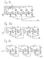
- circuit arrangements according to FIGS. 9b, 9c, 9d and 9e are modified exemplary embodiments of the circuit arrangement according to FIG. 9a, which can be derived from the circuit arrangement according to FIG. 9a and the mathematical approach.
- S are summers, B integrators, R feedbacks, A decouplings, P potentiometers that can be set to coefficients and 1 inverter.
- the three integrators do not follow one after the other, but only two. A third integrator is switched separately.
- H p p 2nd + c 2nd p + c 1 d 4th p 2nd + d 3rd p + d 2nd ⁇ p + c O d 1 p + d O
- the modified circuit arrangement according to the invention according to FIG. 9c was realized from the mathematical approach to a fourth-order equation with four integrators arranged one behind the other.
- H p p 4th + e 3rd p 3rd + e 2nd p 2nd + e 1 p + e O f 4th p 4th + f 3rd p 3rd + f 2nd p 2nd + f 1 p + f O
- the modified circuit arrangement according to the invention according to FIG. 9d was not implemented with four integrators in series compared to the circuit arrangement according to the invention from FIG. 9c, but rather with two times two integrators arranged one behind the other.
- H p p 2nd + g 3rd p + g 2nd H 5 p 2nd + h 4th p + h 3rd ⁇ p 2nd + g 1 p + g O H 2nd p 2nd + h 1 p + h O
- the modified circuit arrangement according to Fig. 9e shows that an embodiment is also possible in which the integrators are not connected in series directly as in Fig. 9a, but each integrator is visible in a circuit diagram closed by feedback and decoupling, and these circuit arrangements are then simply strung together.
- H p p + i 2nd k 5 p + k 4th ⁇ p + i 1 k 3rd p + k 2nd ⁇ p + i O k 1 p + k O
- the predistorted signal which is proportional to acceleration or damping, is suitable for being sent directly to the power amplifier for the electrodynamic converter in order to compensate for its own behavior.
- This type of equivalent circuit constructed with passive components can also be approximated by a compensation circuit according to the invention. Because there is no voice coil influence, you only get a second order approach. The coefficients are determined using the same iteration method.
- the disadvantages of this circuit arrangement are that current-impressed amplifiers are not common because they are very difficult to dimension correctly and are easily unstable. Damping of the membrane movement by the current of the amplifier is also not possible with current-impressed amplifiers, but it is possible with voltage-impressed amplifiers.
- a digital computing circuit can also be used. This possibility, which is particularly advantageous when the electrical signals already exist as digital signals when converting electrical into acoustic signals, is described below.
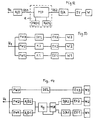
- FIG. 12 shows the block diagram of a corresponding device which is used to generate a predistorted control signal for the electroacoustic transducer derived from the original input signal.
- the predistortion must be dependent on the instantaneous course of the input signal and must be such that the inadequacies of the real electrodynamic converter, including the surrounding medium, are compensated for as far as possible.
- the original input signal U 1 is converted by an analog / digital converter A / D into a sequence of digital signals DS1.
- the digital signals DS1 which are output with a high repetition frequency (sampling frequency) of 100 kHz, for example, against the highest frequency of the input signal represent the binary coding in each case one of e.g. 128 different amplitude values.
- Each e.g. 7-bit date thus represents the (instantaneous) amplitude values present at the time of sampling in the time course of the input signal U 1.
- the sequence of digital signals DS1 is fed to the data inputs of a microcomputer R, which essentially consists of a microprocessor MP, at least one programmable read-only memory PROM and a read / write memory RAM as working memory, and a number of auxiliary devices, which are not dealt with in more detail is known.
- a microcomputer R which essentially consists of a microprocessor MP, at least one programmable read-only memory PROM and a read / write memory RAM as working memory, and a number of auxiliary devices, which are not dealt with in more detail is known.
- All the characteristic values relevant to the reproduction quality of the electroacoustic transducer for example an electrodynamic loudspeaker built into a housing with an upstream power amplifier or a microphone, are stored in the read memory PROM. These parameters relate to variables such as slip, mass inertia of the sound-emitting membrane and the upstream air volume, clamping and restoring forces, damping, resonance frequencies, etc., as well as frequency response and internal resistance of the power amplifier, if applicable.
- the digital signals DS1 entered into the computer which are now referred to as primary digital signals, are converted into secondary digital signals DS2 in accordance with the characteristic converter characteristic values.
- the computer R requires at least three successive samples of the curve course of the input signal. He can then see both the steepness and the curvature of the curve. The changes in the curve of the input signal U 1 which are of particular interest for the present purpose can be determined by comparison with previous samples.
- the sequence of the secondary digital signals DS2 is converted by a digital / analog converter D / A connected to the data output of the microcomputer R into an analog control signal U2, which is used to control the electroacoustic converter W.
- the electroacoustic transducer W is preceded by a power amplifier EV, which only amplifies the analog control signal U2. Since the characteristics of the power amplifier EV, in particular its frequency response and internal resistance, are included in the transmission chain from the original input signal U 1 to the acoustic oscillation, as already mentioned, these variables must also be taken into account together with the characteristic converter characteristic values when calculating the secondary digital signals DS2 .
- the entire frequency range of the input signal is usually divided into, for example, three sub-frequency ranges.
- a specially designed loudspeaker is provided for each sub-frequency range.
- the frequency range is divided by crossovers, which can be designed as LC elements, as filters with operational amplifiers or as digital filters. The latter is particularly useful in connection with digital recording.
- a delay element DEL is provided in the highest partial frequency range.
- the electroacoustic transducers and the upstream power amplifiers are designated W1 to W3 and EV1 to EV3.
- a clock-controlled shift register arrangement can also be provided, which, however, must be preceded by an analog / digital converter and a digital / analog converter.
- the analog / digital converter can be omitted in connection with digital recording.
- the shift register arrangement can be replaced by a further microcomputer, the sole task of which is now to delay the signal.
- the primary digital signals DS11 and DS12 of both partial frequency ranges are the data inputs of a common microcomputer Rg alternately fed and also processed alternately.
- a prerequisite for this is a sufficiently high processing speed of the microcomputer Rg and, of course, adapted programming.
- the secondary digital signals output by the microcomputer Rg must be distributed according to their affiliation to the two channels assigned to the low and mid range. This is done with the aid of a multiplexer MUX controlled by the microcomputer Rg. However, the multiplexer MUX can be omitted if the subsequent digital / analog converters D / A1 and D / A2 are equipped for a clock-controlled takeover of the digital input information and the takeover clocks which are synchronous with the data output of the microcomputer R g are mutually out of phase.
Description
Die Erfindung bezieht sich auf eine Einrichtung nach dem Oberbegriff des Patentanspruchs 1.The invention relates to a device according to the preamble of
Alle elektroakustischen Wandler sind mechanische Schwingsysteme, die durch Eigenwerte wie Federkonstante, Masse, sowie Dämpfung gekennzeichnet sind. Lautsprecher, d.h. Wandier, die elektrische Signale empfangen und akustische Signale abgeben, werden durch den Strom eines Verstärkers z.B. mit Hilfe einer Schwingspule zu erzwungenen Schwingungen angeregt und bedämpft. Umgekehrt stellen Mikrofone Wandler dar, die akustische Signale in elektrische Signale umsetzen. Bei elektrodynamischen Mikrofonen geschieht dies ebenfalls mit Hilfe einer an einer Membran befestigten Schwingspule. Elektrodynamische Tonabnehmersysteme nehmen auch mechanische Schwingungen auf und erzeugen elektrische Signale mit Hilfe von Schwingspulen. Aus diesem Grunde bestehen zwischen elektrodynamischen Mikrofonen und elektrodynamischen Tonabnehmersystemen keine grundsätzlichen Unterschiede.All electroacoustic transducers are mechanical vibration systems, which are characterized by their own values such as spring constant, mass and damping. Speakers, i.e. Wanders that receive electrical signals and emit acoustic signals are e.g. with the help of a voice coil excited and damped vibrations. Conversely, microphones are transducers that convert acoustic signals into electrical signals. With electrodynamic microphones, this is also done with the help of a voice coil attached to a membrane. Electrodynamic pickup systems also pick up mechanical vibrations and generate electrical signals using voice coils. For this reason, there are no fundamental differences between electrodynamic microphones and electrodynamic pickup systems.
Durch das Konstruktions- bzw. Funktionsprinzip der Zusammenkoppelung der verschiedenen Einflüsse, die sich auch gegenseitig wieder beeinflussen, ergeben sich zwei gravierende Hauptfehler, die gleichermaßen für elektrodynamische Lautsprecher und Mikrofone gelten.The design and functional principle of coupling the various influences, which also influence each other again, result in two major main errors that apply equally to electrodynamic loudspeakers and microphones.
Aufgrund der Eigenwerte des Schwingsystems ergibt sich über einen größeren Frequenzbereich eine charakteristische Übertragungsfunktion. Typisch für den sogenannten Amplitudenfrequenzgang ist z.B. der nichtlineare Verlauf mit Resonanzstellen und der geringe Wirkungsgrad am oberen und unteren Ende des Übertragungsbereichs. Als Beispiel hierfür zeigt ein üblicher, weich aufgehängter, in ein geschlossenes Gehäuse eingebauter Baßlautsprecher von ca. 30 cm Ø bei 20 Hz nur eine geringe Schalldruckwirkung mit zu kleinen Amplitudenwerten, erzielt aber bei seiner Resonanzfrequenz im Bereich von ca. 40 - 80 Hz Überlautstärke mit zu großen Amplitudenwerten und nimmt gegen hohe Frequenzen wieder an Wirksamkeit in der Schallübertragung durch zu kleine Amplitudenwerte ab. Anschaulich ist das Amplitudenverhältnis über das auf die Resonanzfrequenz bezogene Frequenzverhältnis in Fig. 1 mit unterschiedlichem Dämpfungsfaktor α dargestellt. Diese Darstellung ist bekannter Stand der Technik und wird hier nicht weiter erläutert.Due to the eigenvalues of the vibration system, a characteristic transfer function results over a larger frequency range. Typical for the so-called amplitude frequency response is e.g. the non-linear course with resonance points and the low efficiency at the upper and lower end of the transmission range. As an example of this, a conventional, softly suspended bass loudspeaker of approx. 30 cm Ø at 20 Hz built into a closed housing shows only a low sound pressure effect with amplitude values that are too low, but achieves over-loudness with its resonance frequency in the range of approx. 40 - 80 Hz too large amplitude values and decreases again against high frequencies effectiveness in sound transmission due to too small amplitude values. The amplitude ratio is clearly shown by the frequency ratio related to the resonance frequency in FIG. 1 with a different damping factor α. This representation is known prior art and is not further explained here.
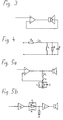
Aufgrund der Masse und der Dämpfung des Schwingsystems werden bei impulsartig einsetzenden Schwingungen jeder Frequenz deutlich erkennbar die Ein- und Ausschwingvorgänge verzerrt. Dies kommt daher, daß solche Schwingsysteme, unterhalb und oberhalb der Resonanzfrequenz angeregt, verschiedene Phasenlagen gegenüber dem anregenden Signal haben. Anschaulich ist der Phasenwinkelverlauf über das auf die Resonanzfrequenz bezogene Frequenzverhältnis in Fig. 2 für verschiedene Dämpfungsfaktoren α dargestellt. Auch diese Darstellung ist bekannter Stand der Technik und wird hier nicht weiter erläutert.Due to the mass and damping of the vibration system, the swinging-in and swinging-out processes are clearly distorted in the case of pulsating vibrations of any frequency. This is because such vibrating systems, excited below and above the resonance frequency, have different phase positions with respect to the exciting signal. The phase angle curve over the frequency ratio related to the resonance frequency is illustrated in FIG. 2 for different damping factors α. This representation is also known prior art and is not further explained here.
Die Membran fängt bei Schwingungsimpulsen oberhalb und unterhalb der Resonanzfrequenz an, sich gleichsinnig zu bewegen, erreicht aber im Fall von Impulsen in der Nähe und unter der Resonanzfrequenz, vor allem während der ersten halben Schwingungsperiode, nur geringe Amplitudenwerte, da sich im Einschwingvorgang die Phasenverschiebung vollzieht. Erst wenn sich die der Frequenz entsprechende Phasenverschiebung vollzogen hat, werden die dem anregenden Signal entsprechenden Amplitudenwerte, allerdings phasenverschoben, erreicht.The membrane begins to move in the same direction with vibration pulses above and below the resonance frequency, but only reaches low amplitude values in the case of pulses near and below the resonance frequency, especially during the first half of the oscillation period, since the phase shift occurs during the transient process . It is only when the phase shift corresponding to the frequency has taken place that the amplitude values corresponding to the exciting signal are reached, albeit out of phase.
Impulsartige Schwingungseinsätze, wie das Anreißen einer Gitarrensaite, das Anschlagen eines Tons am Klavier oder das Schlagen auf eine Trommel, zeigen beim ersten Anschlag das Amplitudenmaximum und schwingen dann in der angerissenen Tonfrequenz. Ein Lautsprechersystem oder Mikrofon, das im Bereich seiner Resonanzfrequenz betrieben wird, muß bei solchen Impulsen erst langsam einschwingen, bis es die der Frequenz entsprechende Phasenlage hat, und erreicht erst dann je nach Güte meist nach einer oder zwei vollen Schwingungsperioden die Maximalamplitude. Bei plötzlicher Bedämpfung, dadurch, daß die schwingende Gitarren- oder Klaviersaite oder das Fell der Trommel plötzlich angehalten werden, schwingt der Wandler mindestens um eine durch die Phasenverschiebung vorgegebene Zeitdauer nach. Im anschließenden Ausschwingvorgang wird die mehr oder weniger gut bedämpfte Eigen- oder Resonanzfrequenz des Wandlers erkennbar.Impulse-like vibrations, such as striking a guitar string, striking a note on the piano or hitting a drum, show the maximum amplitude when struck the first time and then vibrate in the torn tone frequency. A loudspeaker system or microphone, which is operated in the range of its resonance frequency, must first settle slowly with such pulses until it has the phase position corresponding to the frequency, and only then, depending on the quality, usually reaches the maximum amplitude after one or two full oscillation periods. In the event of sudden damping, because the vibrating guitar or piano string or the drum head is suddenly stopped, the transducer resonates at least for a period of time predetermined by the phase shift. In the subsequent decay process, the more or less well damped natural or resonant frequency of the transducer can be seen.
Nur reine Sinustöne wertet das menschliche Gehör lautstärkemäßig nach der Amplitude aus. Tongemische, aus denen Musik immer besteht, werden anhand der Hüllkurve ausgewertet.The human ear only evaluates the volume according to the amplitude of pure sine tones. Mixtures of sounds that always make up music are evaluated using the envelope.
Während die Klangverfälschungen des Wandlersystems durch Fehler im Amplitudenfrequenzgang, die als zu laute oder zu leise Tonlagen wahrgenommen werden, bei der Musikübertragung selten stören, da man sowieso nie genau beurteilen kann, ob nicht der Musiker selbst diese Tonlage lauter oder leiser gespielt hat, werden Fehler bei den Ein- und Ausschwingvorgängen besonders bei impulsreicher Musik als Klangverfärbung wahrgenommen. Durch die Ein- und Ausschwingfehler wird die Hüllkurve (Enveloppe) verändert. Außerdem beeinträchtigen Phasenfehler die Ortbarkeit der Schallquellen und erzeugen dadurch eine künstliche Räumlichkeit. Vor allem die Fehler bei den Ein- und Ausschwingvorgängen sowie eine beeinträchtigte Ortbarkeit der Schallquellen lassen den Hörer erkennen, daß die Musik nicht live ist.While the sound distortions of the transducer system due to errors in the amplitude frequency response, which are perceived as too loud or too quiet pitches, rarely interfere with the music transmission, since anyway you can never judge exactly whether the musician himself played this pitch louder or quieter, errors in the swing-in and swing-out processes are perceived as sound discoloration, especially with pulsating music. The envelope curve is changed by the transient and decay errors. In addition, phase errors affect the location of the sound sources and thus create an artificial spatiality. Above all, the errors in the swing-in and swing-out processes as well as an impaired location of the sound sources let the listener recognize that the music is not live.
Verfahren, die mit Equalizern die unterschiedliche Lautstärkebeeinflussung in den verschiedenen Frequenzbereichen ermöglichen und damit den ersten Fehler, also allein den Amplitudenfrequenzgang, verbessern, sind bekannt. Nachteilig hierbei ist, daß die Fehler im Phasenfrequenzgang und damit die Ein-und Ausschwingvorgänge sowie die Ortbarkeit nicht verbessert, sondern eher noch verschlechtert werden.Methods are known which use equalizers to influence the different volume levels in the different frequency ranges and thus improve the first error, ie the amplitude frequency response alone. The disadvantage here is that the errors in the phase frequency response and thus the transient and decay processes as well as the positionability are not improved but rather worsened.
Aus der DE-C-31 30 353 ist auch bereits ein Verfahren bekannt, das allein die Ein- und Ausschwingfehler verbessert. Nachteilig hierbei ist, daß, wenn keine Impulse im Tonmaterial vorkommen, der Fehler im Amplitudenfrequenzgang nicht verbessert wird.From DE-C-31 30 353 a method is already known which alone improves the swing-in and swing-out errors. The disadvantage here is that if there are no pulses in the sound material, the error in the amplitude frequency response is not improved.
Es wurde auch versucht, die prinzipbedingt entstehenden Fehler der dynamischen Wandler bei der Umsetzung von einer elektrischen in eine akustische Schwingung durch Rückkopplung zu kompensieren. Fig. 3 zeigt die bekannte Anordnung eines Lautsprechers mit einem Sensor für die Membranbewegung.Attempts have also been made to compensate for the principle-related errors of the dynamic transducers when converting from electrical to acoustic vibration by means of feedback. Fig. 3 shows the known arrangement of a loudspeaker with a sensor for the membrane movement.
Hierzu wird die Bewegung der Membran kapazitiv, induktiv, piezoelektrisch oder optisch abgetastet und die so erzeugten elektrischen Istwertsignale mit den Sollwertsignalen verglichen. Die Nachregelung erfolgt über einen Differenzverstärker. Die kapazitiven Bewegungsaufnehmer erfassen neben der Gesamtmembranbewegung aber auch sämtliche Partialschwingungen der Membran, die induktiven Aufnehmer bewegen sich im stark wechselnden Magnetfeld, das durch die stromdurchflossene Erregerwicklung beeinflußt wird. Sie erlauben deshalb nur eine grobe Fehlererkennung. Die Piezo-Aufnehmer sind relativ schwer und vergrößern durch ihr Eigengewicht den ursächlich zu korrigierenden Fehler. Für den Mittel- und Hochtonbereich sind sie nicht einsetzbar. Die optischen Aufnehmer mit eigener Steuerelektronik sind unwirtschaftlich teuer.For this purpose, the movement of the membrane is scanned capacitively, inductively, piezoelectrically or optically and the electrical actual value signals generated in this way are compared with the setpoint signals. The readjustment is carried out via a differential amplifier. The capacitive motion sensors record not only the entire diaphragm movement but also all partial vibrations of the diaphragm, the inductive sensors move in the strongly changing magnetic field, which is influenced by the excitation winding through which current flows. They therefore only allow a rough detection of errors. The piezo transducers are relatively heavy and, due to their own weight, increase the error to be corrected. They cannot be used for the mid and high range. The optical pickups with their own control electronics are uneconomically expensive.
Wegen der phasendrehenden Eigenschaften des Lautsprechers und des Aufnehmers würde der Regelkreis bei hoher Schleifenverstärkung ins Schwingen geraten. Um dieses zu verhindern, muß die Schleifenverstärkung auf kleine Werte, z.B. 20, reduziert werden, was die Wirksamkeit der Rückkopplung stark beeinträchtigt.Because of the phase-changing properties of the loudspeaker and the transducer, the control loop would start to oscillate if the loop gain was high. To prevent this, the loop gain must be set to small values, e.g. 20, can be reduced, which greatly affects the effectiveness of the feedback.
Durch Nachregelung wird außerdem immer nur jeweils der auftretende Amplitudenfehler erkennbar, erfaßbar und regelbar.By means of readjustment, only the amplitude error that occurs is always recognizable, detectable and controllable.
Wenn bei Impulsen Fehler in der Phasenlage auftreten, äußern sie sich z.B. in zu kleinen Amplituden. Eine reine Amplitudennachregelung erfordert aber in dem Fall des noch gegenphasigen Einschwingens überhohe Korrekturstromimpulse, die der Verstärker dadurch, daß er seine Leistung schon für den Musikimpuls zur Verfügung stellte, meist nicht liefern kann. Im übrigen können derartige Nachregelungen der Membran erst mit einiger Verzögerung nach Auftreten des Fehlers wirksam werden und somit, besonders bei falscher Phasenlage, die Fehler nie grundsätzlich verhindern.If errors occur in the phase position of pulses, they are expressed, for example in too small amplitudes. However, a pure amplitude adjustment requires excessive correction current pulses in the case of the phase-in transient oscillation, which the amplifier usually cannot deliver by providing its power for the music pulse. In addition, such readjustments of the membrane can only take effect with a certain delay after the error has occurred, and thus, in particular if the phase position is incorrect, the errors never fundamentally prevent.
Bei hohen Amplitudenänderungen, wie sie in der modernen Unterhaltungs- und Tanzmusik häufig auftreten, kann es durch die hohen Nachregelungskorrektursignale zu kurzfristigen Übersteuerungen des Endverstärkers und damit zu hohen Klirrfaktoren kommen.With high amplitude changes, as they often occur in modern entertainment and dance music, the high readjustment correction signals can lead to short-term overloads of the power amplifier and thus to high distortion factors.
Während die Nachregelung in der Praxis bei den Amplitudenfehlern in der Übertragungsfunktion des Lautsprechers z.B. bei seiner Resonanzfrequenz über mehrere Schwingungsperioden einwirkend ausgleichend wirken kann, zeigt sie bei der von der Phasenlage abhängigen Verbesserung der Ein- und Ausschwingvorgänge bei plötzlichen Amplitudenänderungen in der entscheidenden ersten halben Schwingungsperiode nur wenig Wirkung. Nachregelungen der beschriebenen Art lassen sich naturgemäß bei Mikrofonen und Tonabnehmern nicht anwenden.While the readjustment in practice with the amplitude errors in the transfer function of the loudspeaker e.g. at its resonance frequency can have a balancing effect over several oscillation periods, it shows little effect in the phase-dependent improvement of the transient and decay processes in the event of sudden changes in amplitude in the decisive first half oscillation period. Readjustments of the type described cannot, of course, be applied to microphones and pickups.
Um die Probleme mit den Sensoren an der Lautsprechermembran zu vermeiden, wurde auch schon versucht, mit Hilfe einer elektrischen Nachbildung des Lautsprechers als Ersatzschaltung nach Fig. 4 zu arbeiten.In order to avoid the problems with the sensors on the loudspeaker membrane, attempts have already been made to work with the aid of an electrical simulation of the loudspeaker as an equivalent circuit according to FIG. 4.
Bei dieser aus passiven Bauteilen, mit Spulen, Kondensatoren und Widerständen aufgebauten elektrischen Ersatzschaltung hängen die verschiedenen Kennwerte und Parameter voneinander ab und wirken in gleicher Weise wie beim elektrodynamischen Lautsprecher zusammen. Ändert sich beim elektrodynamischen Wandler z.B. seine schwingende Masse, so hat dies Änderungen seiner Phasenfehler im Tief- und im Hochtonbereich sowie Änderungen im gesamten Übertragungsbereich des Schalldruckverlaufs zur Folge. Jede Veränderung eines Werts der passiven Bauteile der elektrischen Ersatzschaltung wirkt sich somit im gesamten Übertragungsbereich der Ersatzschaltung aus und ist nicht auf einen begrenzten Frequenzabschnitt des Übertragungsbereichs der Schaltung beschränkt, wie es beispielsweise bei Einstellmaßnahmen mit Hilfe von Equalizern der Fall ist.In this electrical equivalent circuit made up of passive components, with coils, capacitors and resistors, the various characteristic values and parameters depend on each other and act in the same way as with the electrodynamic loudspeaker. Does the electrodynamic converter change e.g. its vibrating mass, this results in changes in its phase errors in the low and high frequencies as well as changes in the entire transmission range of the sound pressure curve. Any change in a value of the passive components of the electrical equivalent circuit thus has an effect in the entire transmission range of the equivalent circuit and is not limited to a limited frequency section of the transmission range of the circuit, as is the case, for example, with adjustment measures with the aid of equalizers.
Die elektrischen Werte als Beispiel für einen Baß-, Mittel- und Hochtonlautsprecher nach Fig. 4 sind in der folgenden Tabelle zusammengestellt und zeigen große Unterschiede auf.
Ein anderer Baßlautsprecher mit 37 Hz Resonanzfrequenz kann aber bereits durchaus Werte von C = 300 µF, L = 60 mH und R = 50 Ω haben. Auf verschiedene Lautsprecher abgleichbare passive Bauteile in diesem Größenordnungsbereich sind nur mit unverhältnismäßig großem, unwirtschaftlichem Aufwand machbar.Another bass speaker with a resonance frequency of 37 Hz can already have values of C = 300 µF, L = 60 mH and R = 50 Ω. Passive components in this order of magnitude that can be matched to different loudspeakers can only be achieved with a disproportionately large, uneconomical effort.
Durch eine Ersatzschaltung für den tatsächlichen Lautsprecher versuchte man, ein besseres Korrektursignal zu bekommen. Die Ersatzschaltung wird dazu in einen Rückkopplungskreis nach Fig. 5a eingesetzt. Der Nachteil dieser Schaltung ist, daß diskret mit Spulen, Kondensatoren und Widerständen aufgebaute Ersatzschaltungen, sowie auch die elektrodynamischen Wandler selbst, schon bei kleinen Bauteil- und Fertigungstoleranzen bereits erhebliche Unterschiede im zusammengebauten Endprodukt aufweisen. Eine solche mit diskreten Bauteilen aufgebaute Ersatzschaltung ist deshalb nur schlecht an die tatsächlichen Lautsprecherverhältnisse anzugleichen, nicht abstimmbar und teuer. Die diskret mit Spulen, Kondensatoren und Widerständen aufgebaute Ersatzschaltung nach Fig. 4 kann auch invers in Reihe mit dem Lautsprecher angeordnet sein (Fig. 5b), was aus der US-A-3 988 541 bekannt ist. Hierbei wurde außerdem auch der Strom eingeprägt, um die Anteile der Schwingspulenimpedanz und Schwingspuleninduktivität in der Ersatzschaltung vernachlässigen zu können. Aber auch hier bleiben die Nachteile der großen Bauteiltoleranzen von Lautsprecher und Ersatzschaltung und der fast unmöglichen Abgleichbarkeit für einen bestimmen Lautsprecher, die dieses Verfahren für die Praxis nicht anwendbar machen.An equivalent circuit for the actual loudspeaker was used to try to get a better correction signal. The equivalent circuit is used for this purpose in a feedback circuit according to FIG. 5a. The disadvantage of this circuit is that replacement circuits constructed discretely with coils, capacitors and resistors, as well as the electrodynamic converters themselves, already show considerable differences in the assembled end product, even with small component and manufacturing tolerances. Such an equivalent circuit constructed with discrete components is therefore difficult to match to the actual loudspeaker conditions, cannot be tuned and is expensive. 4 may also be arranged inversely in series with the loudspeaker (FIG. 5b), which is known from US Pat. No. 3,988,541. The current was also injected in order to neglect the parts of the voice coil impedance and voice coil inductance in the equivalent circuit. However, the disadvantages of the large component tolerances of the loudspeaker and equivalent circuit and the almost impossible comparability for a specific loudspeaker remain here, which make this method not applicable in practice.
Es ist auch nicht möglich, die vorstehend beschriebenen Nachteile der mit diskreten Bauteilen aufgebauten elektrischen Ersatzschaltung eines Lautsprechers zu umgehen, indem man seine leichter abstimmbare elektrische Ersatzschaltung als Analogrechenschaltung mit aktiven Bauteilen nach Fig. 6 verwendet. Da die exakte elektrische Nachbildung für ein Lautsprechersystem als Analogrechenschaltung bereits aus mehreren Rückkopplungen besteht und durch eine weitere Rückkopplung die Eigenwerte verändert, kann sie nicht wie eine mit passiven Bauteilen aufgebaute Lautsprecherersatzschaltung nach Fig. 5a in einen Rückkopplungszweig geschaltet werden. Die Schaltung wird dadurch auch instabil und kommt ins Schwingen.It is also not possible to avoid the disadvantages described above of the electrical equivalent circuit of a loudspeaker constructed with discrete components by using its more easily tunable electrical equivalent circuit as an analog computing circuit with active components according to FIG. 6. Since the exact electrical replica for a loudspeaker system as an analog arithmetic circuit already consists of several feedbacks and changes the eigenvalues through a further feedback, it cannot be switched into a feedback branch like a loudspeaker replacement circuit constructed with passive components according to FIG. 5a. The circuit also becomes unstable and starts to vibrate.
Die Analogrechenschaltung für den Lautsprecher sinngemäß nach Fig. 5b invers in Reihe mit dem Lautsprecher zu betreiben, geht auch nicht, weil diese wie alle elektronischen Schaltungen mit Operationsverstärkern nur in einer Richtung arbeitet und ein Vertauschen der Ein- und Ausgänge zur Wirkungsumkehr nicht möglich ist.To operate the analog arithmetic circuit for the loudspeaker in accordance with FIG. 5b inversely in series with the loudspeaker is also not possible because, like all electronic circuits with operational amplifiers, it only works in one direction and the inputs and outputs cannot be interchanged to reverse the effect.
Aus der US-A-4 052 560 ist eine Kompensationseinrichtung der eingangs genannten Art für Wiedergabefehler eines elektroakustischen Wandlers bekannt, die zur Begradigung des Schalldruckverlaufs am oberen und unteren Ende des Übertragungsbereichs von elektrodynamischen Lautsprechern eingesetzt wird. Die Schaltungsanordnung besteht aus aktiven Bauteilen. Die einzelnen Schaltungsabschnitte bzw. Filter sind zur separaten Kompensation von Fehlern in unterschiedlichen Frequenzbereichen wirksam, d.h. Einstellmaßnahmen in einem Schaltungsabschnitt betreffen nur den entsprechenden Frequenzbereich und wirken sich nicht auf den gesamten Übertragungsbereich des Wandlers aus. Das komplexe Übertragungsverhalten des Wandlers und seine Übertragungsfehler vermag die bekannte Schaltungsanordnung daher nicht voll zu berücksichtigen bzw. zu kompensieren. Es ist zwar eine annähernde Linearisierung des Frequenzgangs bzw. Schalldruckverlaufs vorgesehen. Nach Durchführung der Kompensation sind indessen noch deutliche Phasenfehler vorhanden.From US-A-4 052 560 a compensation device of the type mentioned for playback errors of an electroacoustic transducer is known, which is used to straighten the sound pressure curve at the upper and lower end of the transmission range of electrodynamic loudspeakers. The circuit arrangement consists of active components. The individual circuit sections or filters are effective for the separate compensation of errors in different frequency ranges, i.e. Adjustment measures in a circuit section only affect the corresponding frequency range and do not affect the entire transmission range of the converter. The known circuit arrangement cannot fully take into account or compensate for the complex transmission behavior of the converter and its transmission errors. An approximate linearization of the frequency response or sound pressure curve is provided. After the compensation has been carried out, there are still significant phase errors.
Gemäß einem Vorschlag von R. A. Greiner und M. Schoessow, "Electronic Equalization of Closed-Box Loudspeakers", J. Audio Eng. Soc., 1983, Seiten 125 - 134 werden zur Verbesserung des Frequenzgangs und des Einschwingverhaltens eines Lautsprechersystems die Pole der Übertragungsfunktion des Wandlers durch Nullstellen in der Übertragungsfunktion eines äquivalenten elektronischen Filters bzw. Equalizers ausgeglichen. Eine verzerrungfreie Wiedergabe von Rechteckimpulsen ermöglicht dieser Vorschlag nicht.According to a proposal by RA Greiner and M. Schoessow, "Electronic Equalization of Closed-Box Loudspeakers", J. Audio Eng. Soc., 1983, pages 125-134 become the poles of the transducer transfer function to improve the frequency response and transient response of a speaker system compensated for by zeroing in the transfer function of an equivalent electronic filter or equalizer. This proposal does not enable distortion-free reproduction of rectangular pulses.
Aus der US-A-4 340 778 ist auch bereits bekannt, durch eine Schaltung den Einfluß der Schwingspule, des akustischen Wirkungsgrades, der mechanischen Aufhängung, der Dämpfung usw. jeweils einzeln zu kompensieren. Dabei werden mehrere Kompensationsschaltungen nacheinander angeordnet. Da aber alle Einflüsse des mechanischen Schwingsystems des elektrodynamischen Lautsprechers voneinander abhängig sind und sich auch gegenseitig wieder beeinflussen, können solche nur in begrenzten Frequenzbereichen wirksamen Kompensationsschaltungen die Fehler nicht wirksam verhindern, sondern schaffen vielmehr neue, andere Fehler, die sich ebenfalls als Klirrfaktoren oder Klangverfälschungen äußern.From US-A-4 340 778 it is also known to compensate individually for the influence of the voice coil, the acoustic efficiency, the mechanical suspension, the damping, etc., by means of a circuit. Several compensation circuits are arranged one after the other. However, since all influences of the mechanical vibration system of the electrodynamic loudspeaker are dependent on one another and also influence each other again, such compensation circuits which are only effective in limited frequency ranges cannot effectively prevent the errors, but rather create new, other errors which are also manifested as distortion factors or sound distortions .
Schaltungen zur beliebigen Beeinflussung des Schalldruckverlaufs von Lautsprechern sind Equalizer. Diese Filterschaltungen eignen sich zur Linearisierung des Schalldruckverlaufs bzw. zur Begradigung des Amplitudenfrequenzgangs. Bei den sogenannten graphischen Equalizern ist der Übertragungsfrequenzbereich von 20 bis 20000 Hz in vorher festgelegte, frequenzmäßig begrenzte Teilbereiche aufgeteilt, in denen jeweils Korrekturen durchgeführt werden. Eine Einstellung für andere Korrekturbereiche ist nicht möglich. Die sogenannten parametrischen Equalizer, von denen die US-A-4 052 560 eine Schaltungsanordnung beschreibt, ermöglichen auch die nachträgliche Einstellung von speziellen Teilfrequenzbereichen und der Filtercharakteristik, wodurch eine Anpassung an beliebige Korrekturstellen erfolgen kann.Circuits to influence the sound pressure curve of loudspeakers in any way are equalizers. These filter circuits are suitable for linearizing the sound pressure curve or for straightening the amplitude frequency response. In the case of the so-called graphic equalizers, the transmission frequency range from 20 to 20,000 Hz is divided into predetermined, frequency-limited sub-ranges, in which corrections are carried out in each case. A setting for other correction areas is not possible. The so-called parametric equalizers, of which US Pat. No. 4,052,560 describes a circuit arrangement, also enable the subsequent adjustment of special partial frequency ranges and the filter characteristic, as a result of which adaptation to any correction points can take place.
Bei den graphischen Equalizern wird in der Regel der Phasenfrequenzgang des Wandlers nicht verbessert, sondern häufig noch der Phasenfehler der Equalizerschaltungen diesem überlagert. Auch die parametrischen Equalizer ermöglichen prinzipbedingt nur sehr beschränkte Verbesserungen des Phasenfrequenzgangs.With the graphic equalizers, the phase frequency response of the converter is generally not improved, but often the phase error of the equalizer circuits is superimposed on it. The parametric equalizers also allow for very limited improvements in the phase frequency response.
Ein wesentlicher Vorteil der Equalizer ist die Beschränkung der Einstellmöglichkeiten von deren aktiven Filtern auf relativ kleine Teilfrequenzbereiche, wodurch die Einstellung beliebiger, auch linearer Schalldruckverläufe relativ einfach und übersichtlich ist.A major advantage of the equalizer is the limitation of the setting options of its active filters to relatively small sub-frequency ranges, which makes setting any, even linear, sound pressure curves relatively easy and clear.
Die komplexen Zusammenhänge der einzelnen Parameter beim elektrodynamischen Wandler, die sich in ihrer gegenseitigen Abhängigkeit über den gesamten Übertragungsbereich erstrecken, werden bei den Equalizern nur unzureichend erfaßt. Durch die annähernde Liniarisierung des Schalldruckverlaufs wird der Phasenfrequenzgang mitbeeinflußt, wird jedoch nicht richtig kompensiert. Durch die Korrektur jeweils in Frequenzteilbereichen wird dem komplexen Gesamtzusammenhang des elektrodynamischen Wandlers nicht ausreichend Rechnung getragen. Statt einer Kompensation der Phasenfehler werden diese höchstens auf kleinere Werte gebracht.The complex relationships of the individual parameters in the electrodynamic converter, which in their interdependency extend over the entire transmission range, are only insufficiently recorded in the equalizers. The phase frequency response is influenced by the approximate linearization of the sound pressure curve, but is not properly compensated for. The correction in each case in partial frequency ranges does not take sufficient account of the complex overall relationship of the electrodynamic converter. Instead of compensating the phase errors, these are at most brought to smaller values.
Dies ist ausgeführt in V. Staggs, "Transient-Response Equalization of Sealed-Box Loudspeakers", J. Audio Eng. Soc., 1982, Seiten 906 bis 910, wobei Maßnahmen im Frequenzbereich der Resonanzfrequenz des Wandlers und eines kleinen Teils des darunter stark abfallenden Baßbereichs beschränkt sind. Es werden mehrere Filtercharakteristiken in bezug auf die sich ergebenden Einschwingungsverzerrungen miteinander verglichen. Bei Verwendung biquadratischer Filter mit niedriger Ordnung ergeben sich demnach bessere Einschwingvorgänge als mit einfachen Hochpaß-Filtern höherer Ordnung. In beiden Fällen aber bleiben Fehler bei den Einschwingvorgängen deutlich nachweisbar erhalten. Dies bestätigt, daß mit allen Filtern, die nur in begrenzten Frequenzabschnitten des Übertragungsbereichs eines elektrodynamischen Lautspechers eingesetzt werden, dessen Phasenfehler nur unzureichend kompensiert werden können.This is stated in V. Staggs, "Transient-Response Equalization of Sealed-Box Loudspeakers", J. Audio Eng. Soc., 1982, pages 906 to 910, measures in the frequency range of the resonant frequency of the transducer and a small part of the bass range falling sharply below it being limited. Several filter characteristics are compared with respect to the resulting transient distortion. When using biquadratic filters with a lower order, this results in better transient processes than with simple high-pass filters of a higher order. In both cases, however, errors in the transient process are clearly retained. This confirms that with all filters that are only used in limited frequency sections of the transmission range of an electrodynamic loudspeaker, its phase errors can only be insufficiently compensated for.
In zahlreichen Literaturstellen ist eine Baßentzerrung im unteren Frequenzbereich beschrieben. Die bekannten Schaltungen erfassen oft gar nicht das gesamte mechanische Schwingsystem des elektrodynamischen Lautsprechers in seinem vollen Übertragungsbereich. Außerdem werden diese Schaltungen oft nicht einem einzigen elektrodynamischen Lautsprecher zugeordnet, sondern sie sind Mehrwege-Lautsprecherboxen vorgeschaltet, die Hoch-, Mittel- und Baßlautsprecher sowie eine Frequenzweiche enthalten. Da aber Frequenzweichen selbst Phasenfehler hervorrufen und die Phasenfehler zweier Teilfrequenzlautsprecher bei ihrer überlagerung weitere Fehler erzeugen, kann durch solche Maßnahmen eigentlich nur der Schalldruckverlauf begradigt werden, die Kompensation der Phasenfehler ist nicht möglich.Bass equalization in the lower frequency range is described in numerous references. The known circuits often do not record the entire mechanical vibration system of the electrodynamic loudspeaker in its full transmission range. In addition, these circuits are often not assigned to a single electrodynamic loudspeaker, but they are upstream of multipath loudspeakers which contain high, medium and bass loudspeakers and a crossover network. However, since crossovers themselves cause phase errors and the phase errors of two sub-frequency loudspeakers produce further errors when they are superimposed, such measures can actually only straighten the sound pressure curve; the compensation of the phase errors is not possible.
Der Erfindung liegt die Aufgabe zugrunde, eine Einrichtung zur Kompensation von Wiedergabefehlern eines elektroakustischen, insbesondere nach dem elektrodynamischen Prinzip arbeitenden Wandlers anzugeben, durch welche die im elektrischen Abschnitt des Übertragungswegs auftretenden Signale so verändert werden, daß die systembedingten Fehler mindestens weitgehend ausgeglichen werden. Die Kompensationseinrichtungen sollen aus preiswerten aktiven elektronischen Bauteilen und Einstellgliedern bestehen und in weiten Bereichen auf verschiedene Wandlertypen leicht und individuell einstellbar sein.The invention has for its object to provide a device for compensating playback errors of an electroacoustic, in particular working according to the electrodynamic principle, by which the signals occurring in the electrical section of the transmission path are changed so that the system-related errors are at least largely compensated. The compensation devices should consist of inexpensive active electronic components and setting elements and should be easily and individually adjustable in a wide range to different converter types.
Diese Aufgabe wird durch die Merkmale im kennzeichnenden Teil des Patentanspruchs 1 gelöst.This object is achieved by the features in the characterizing part of
Dadurch, daß die unterschiedlichen Lautsprecherexemplare des gleichen Typs schon bei kleinen Bauteil- und Fertigungstoleranzen große elektrische Unterschiede haben, bedeutet die leichte, individuelle Einstellbarkeit auf das jeweilige Exemplar einen erheblichen Vorteil.The fact that the different loudspeaker copies of the same type have large electrical differences even with small component and manufacturing tolerances means that they are light, individual Adjustability to the respective copy a considerable advantage.
Die Vorteile der Kompensationsschaltung werden noch deutlicher, wenn man berücksichtigt, daß die leichte Einstellbarkeit nicht nur auf Lautsprecher des gleichen Serientyps, sondern sogar auf so unterschiedliche Lautsprechertypen wie Tief-, Mittel- oder Hochtöner genauso leicht möglich ist. Gegenüber dem Herstellungsaufwand passiver, also mit Kondensatoren, Spulen und Widerständen, aufgebauter Ersatzschaltungen mit großen Bauteilwerten, ergibt sich vom Materialaufwand der aktiven elektronischen Bauteile und von der Einstellbarkeit der Stellglieder ein großer Kostenvorteil.The advantages of the compensation circuit are even clearer if one takes into account that the easy adjustability is just as easily possible not only on speakers of the same series type, but even on speakers as different as woofers, mid-range speakers or tweeters. Compared to the manufacturing costs of passive, ie with capacitors, coils and resistors, built-up equivalent circuits with large component values, the material cost of the active electronic components and the adjustability of the actuators result in a great cost advantage.
Dadurch, daß die Kompensationsschaltung aber universell, also für alle elektrodynamischen Lautsprechersysteme und elektrodynamischen Kopfhörer ebenso wie für alle elektrodynamischen Mikrofone und elektrodynamischen Tonabnehmer einsetzbar ist, ergibt sich ein großer Anwendungsbereich mit einem durch Massen- bzw. Serienfertigung bedingten nochmalig steigenden Kostenvorteil und Fertigungsvorteil.However, the fact that the compensation circuit can be used universally, that is to say for all electrodynamic loudspeaker systems and electrodynamic headphones as well as for all electrodynamic microphones and electrodynamic pickups, results in a large field of application with a cost advantage and manufacturing advantage that increase again due to mass or series production.
Wenn im Fall des Einsetzens der Kompensationsschaltung in allen Zweigen einer Mehrweglautsprecherbox die Frequenzweiche nach der DE-C-33 04 402 konstruiert ist und somit allen Frequenzbereichen richtige Einschwingvorgänge und auch gleiche Phasenlage gewährleistet, ergeben sich im Einschwingverhalten des Baß-, Mittel- und Hochtöners bei Tonbursts aus Tongemischen, wie sie in der Musik häufig, z.B. bei Anschlägen von Klavier, Gitarre und Trommel, vorkommen, über die gesamte Mehrweglautsprecherbox keine Phasendrehungen und keine Klangveränderungen mehr durch Überlagerungen von Frequenzbereichen, die unterschiedliche Phasendrehungen erfahren haben. Die Membranen des Hochtöners, Mitteltöners und Baßlautsprechers bleiben bei allen Anregungen, ob durch Impulse oder durch lang anhaltende Töne, in gleicher Phase. Dadurch wird erstmals das Problem der Übergangsfrequenz zwischen Baß- und Mitteltöner oder Mittel- und Hochtöner praxistauglich und kostengünstig gelöst. In der bisherigen Praxis war aus den aufgeführten Gründen immer nur der Kompromiß möglich, daß entweder bei eingeschwungenen Tönen oder bei Impulsen die jeweiligen Membranen sich in Phase bewegen konnten, und akustisch richtige Überlagerungen liefern.If, in the case of the use of the compensation circuit in all branches of a reusable loudspeaker, the crossover is constructed according to DE-C-33 04 402 and thus ensures correct settling and all phases in all frequency ranges, the transient response of the bass, mid-range and tweeters results in Sound bursts from sound mixtures, as they are common in music, for example when striking the piano, guitar and drum, there are no phase shifts and no sound changes over the entire reusable loudspeaker box due to overlapping frequency ranges that have experienced different phase shifts. The membranes of the tweeter, midrange and bass loudspeaker remain in the same phase with all suggestions, whether through impulses or through long-lasting tones. This solves the problem of the crossover frequency between bass and midrange or midrange and tweeter for the first time in a practical and cost-effective way. In the previous practice, for the reasons given, only the compromise was possible that either the respective membranes could move in phase with steady tones or with impulses, and deliver acoustically correct superimpositions.
Ebenso von Vorteil ist, daß beim Lautsprecherbau handelsübliche Lautsprecherexemplare verwendet werden können. Man benötigt keine Spezialanfertigungen, wie z.B. mit Sensoren für eine Nachregelung oder teuren engtolerierten Bauteilen und speziellen Fertigungsverfahren, um bestimmte Kennwerte einzuhalten.Another advantage is that standard loudspeaker specimens can be used in loudspeaker construction. You do not need any special designs, such as with sensors for readjustment or expensive, narrow-tolerance components and special manufacturing processes to maintain certain parameters.
Ein weiterer Vorteil ist, daß sich die elektrischen Kennwerte der Kompensationsschaltung durch Belastung im Betrieb nicht verändern, wie dies bei Spulen und Kondensatoren durch die Erwärmung im Betrieb geschieht. Ebenso vorteilhaft ist, daß Nichtlinearitäten durch Bauteile, wie z.B. bei der Spule durch Hysterese, Sättigung und Wirbelstrom, in der einstellbaren Kompensationsschaltung mit Operationsverstärkern nicht vorkommen.Another advantage is that the electrical characteristics of the compensation circuit do not change during operation, as happens with coils and capacitors due to heating during operation. It is also advantageous that non-linearities due to components such as e.g. in the coil due to hysteresis, saturation and eddy current, do not occur in the adjustable compensation circuit with operational amplifiers.
Die leichte und universelle Abstimmbarkeit ist auch vorteilhaft, wenn ein Wandler zerstört wird und ersetzt werden muß. Hier erbringt die Kompensationsschaltung einen hohen Gebrauchswert bei Reparaturen.The easy and universal tunability is also advantageous if a converter is destroyed and has to be replaced. Here the compensation circuit provides a high utility value for repairs.
Aber auch die Einstellbarkeit auf Lautsprecherentwicklungen in der Zukunft, wie z.B. auf neue Lautsprecher mit magnetischer Flüssigkeit im Luftspalt des Magneten oder Lautsprecher mit neuen Flachmembranen, bringt eine Steigerung des Gebrauchswerts.But also the adjustability to speaker developments in the future, such as on new loudspeakers with magnetic liquid in the air gap of the magnet or loudspeakers with new flat membranes, brings an increase in use value.
Als ein wesentlicher Vorteil der Kompensationsschaltung ist noch hervorzuheben, daß sie durch nur wenige aktive Bauteile äußerst preisgünstig verwirklicht werden kann.A significant advantage of the compensation circuit is also to be emphasized that it can be implemented extremely inexpensively by only a few active components.
Ebenso soll noch der geringe Platzbedarf der Kompensationsschaltung, die ohne weiteres in Größe eines heute üblichen Operationsverstärkers denkbar ist, gegenüber den großen passiven Bauteilen einer Lautsprecherersatzschaltung, z.B. bei der Anwendung im Baßbereich, genannt werden.Likewise, the small space requirement of the compensation circuit, which is easily conceivable in the size of an operational amplifier customary today, compared to the large passive components of a loudspeaker equivalent circuit, e.g. when used in the bass range.
Im folgenden wird die Erfindung anhand schematischer Zeichnungen, Formeln und eines konkreten Anwendungsbeispiels für einen Baßlautsprecher näher beschrieben. In der folgenden Aufstellung sind die bereits behandelten Zeichnungen Fig. 1 bis 6 enthalten.
- Fig. 1
- zeigt das Amplituden-Resonanz-Verhalten bekannter elektrodynamischer Wandler für verschiedene Dämpfungsfaktoren α,
- Fig. 2
- zeigt das Phasen-Resonanz-Verhalten bekannter elektrodynamischer Wandler für verschiedene Dämpfungsfaktoren α,
- Fig. 3
- zeigt das Schema bekannter Membranrückkopplungen bei Lautsprechern,
- Fig. 4
- zeigt eine mit passiven Bauteilen aufgebaute elektrische Ersatzschaltung eines bekannten elektrodynamischen Lautsprechers,
- Fig. 5a
- zeigt das Schema einer Rückkopplung über eine den elektrodynamischen Lautsprecher simulierende, mit passiven Bauteilen aufgebaute, bekannte elektrische Ersatzschaltung,
- Fig. 5b
- zeigt eine zu der Schaltung gemäß Fig. 5a elektrisch gleichwertige Schaltung mit invers und in Reihe geschalteter, bekannter, mit passiven Bauteilen aufgebauter, elektrischer Lautsprecherersatzschaltung für den elektrodynamischen Lautsprecher,
- Fig. 6
- zeigt eine bekannte elektrische Ersatzschaltung eines elektrodynamischen Lautsprechers in einem Aufbau als Analogrechenschaltung,
- Fig. 7
- zeigt eine mit passiven Bauteilen aufgebaute, bekannte elektrische Lautsprecherersatzschaltung für den elektrodynamischen Lautsprecher mit anschließender Differenzierstufe,
- Fig. 8a
- zeigt den Dämpfungsverlauf, der sich aus dem Lautsprecher oder seiner Ersatzschaltung nach Fig. 7 für das Beispiel eines elektrodynamischen Baßlautsprechers ergibt,
- Fig. 8b
- zeigt den Phasenwinkelverlauf, der sich aus dem Lautsprecher oder seiner Ersatzschaltung nach Fig. 7 für das Beispiel eines elektrodynamischen Baßlautsprechers ergibt,
- Fig. 9a
- zeigt den Prinzipaufbau einer erfindungsgemäßen Kompensationsschaltung
mit 3 Integratoren, - Fig. 9b
- zeigt ein abgewandeltes Ausführungsbeispiel einer erfindungsgemäßen Kompensationsschaltung nach Fig. 9a,
- Fig. 9c
- zeigt ein abgewandeltes Ausführungsbeispiel einer erfindungsgemäßen Kompensationsschaltung
mit 4 Integratoren, - Fig. 9d
- zeigt ein abgewandeltes Ausführungsbeispiel einer erfindungsgemäßen Kompensationsschaltung nach Fig. 9c,
- Fig. 9e
- zeigt ein abgewandeltes Ausführungsbeispiel einer erfindungsgemäßen Kompensationsschaltung nach Fig. 9a,
- Fig. 10a
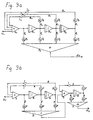
- zeigt den entsprechenden Verlauf der Dämpfungsfunktion der Kompensationsschaltung für das errechnete Beispiel des elektrodynamischen Baßlautsprechers,
- Fig. 10b
- zeigt den entsprechenden Verlauf des Phasenwinkels der Kompensationsschaltung für das errechnete Beispiel des elektrodynamischen Baßlautsprechers,
- Fig. 11a
- zeigt den Verlauf des Dämpfungsfehlers gegenüber der idealen Übertragungsfunktion in einem Diagramm,
- Fig.11b
- zeigt den Verlauf des Phasenfehlers gegenüber dem idealen Phasenverlauf in einem Diagramm,
- Fig. 12
- zeigt ein Blockschaltbild der erfindungsgemäßen Einrichtung unter Verwendung einer digitalen Rechenschaltung,
- Fig. 13
- zeigt eine Einrichtung mit Aufteilung des gesamten Frequenzbereichs des Eingangssignals in drei Teilfrequenzbereiche und
- Fig. 14
- zeigt eine Variante der Einrichtung nach Fig. 13.
- Fig. 1
- shows the amplitude-resonance behavior of known electrodynamic transducers for various damping factors α,
- Fig. 2
- shows the phase-resonance behavior of known electrodynamic transducers for various damping factors α,
- Fig. 3
- shows the diagram of known membrane feedback in loudspeakers,
- Fig. 4
- shows an electrical equivalent circuit of a known electrodynamic loudspeaker constructed with passive components,
- Fig. 5a
- shows the diagram of a feedback via a known electrical equivalent circuit simulating the electrodynamic loudspeaker and constructed with passive components,
- Fig. 5b
- 5a shows an electrically equivalent circuit to the circuit according to FIG. 5a with an inverse and series-connected known loudspeaker circuit constructed with passive components for the electrodynamic speaker,
- Fig. 6
- shows a known electrical equivalent circuit of an electrodynamic loudspeaker in a structure as an analog computing circuit,
- Fig. 7
- 1 shows a known electrical loudspeaker replacement circuit for passive electromechanical loudspeakers for the electrodynamic loudspeaker with subsequent differentiation stage,
- Fig. 8a
- 7 shows the attenuation curve resulting from the loudspeaker or its equivalent circuit according to FIG. 7 for the example of an electrodynamic bass loudspeaker,
- Fig. 8b
- 7 shows the phase angle curve which results from the loudspeaker or its equivalent circuit according to FIG. 7 for the example of an electrodynamic bass loudspeaker,
- Fig. 9a
- shows the basic structure of a compensation circuit according to the invention with 3 integrators,
- Fig. 9b
- shows a modified embodiment of a compensation circuit according to the invention according to FIG. 9a,
- Fig. 9c
- shows a modified embodiment of a compensation circuit according to the invention with 4 integrators,
- Fig. 9d
- 9c shows a modified exemplary embodiment of a compensation circuit according to the invention,
- Fig. 9e
- shows a modified embodiment of a compensation circuit according to the invention according to FIG. 9a,
- Fig. 10a
- shows the corresponding course of the damping function of the compensation circuit for the calculated example of the electrodynamic bass speaker,
- Fig. 10b
- shows the corresponding course of the phase angle of the compensation circuit for the calculated example of the electrodynamic bass speaker,
- Fig. 11a
- shows the course of the damping error compared to the ideal transfer function in a diagram,
- Fig.11b
- shows the course of the phase error compared to the ideal phase course in a diagram,
- Fig. 12
- shows a block diagram of the device according to the invention using a digital arithmetic circuit,
- Fig. 13
- shows a device with division of the entire frequency range of the input signal into three sub-frequency ranges and
- Fig. 14
- shows a variant of the device according to FIG. 13.
Fig. 7 zeigt ein bekanntes Lautsprecherersatzschaltbild mit nachgeschalteter Differenzierstufe. Die Werte für das Beispiel mit dem Baßlautsprecher werden am Baß dynamisch bestimmt, d.h. die komplexe Eingangsimpedanz bei unterschiedlichen Frequenzen gemessen und daraus die Bauteilwerte für die bekannte Ersatzschaltung mathematisch berechnet. Das Verhalten der Ersatzschaltung entspricht exakt dem des Lautsprechers selbst.
An den Eingangsklemmen des Lautsprechers oder auch seiner elektrischen exakten Nachbildung durch die Ersatzschaltung wird die Spannung U₁ angelegt, an den Ausgangsklemmen kann die Spannung U₂ abgegriffen werden.At the input terminals of the speaker or its exact electrical replication by the equivalent circuit, the
Aus dem Verhältnis U₁/U₂ ergibt sich die Dämpfungsfunktion, aus der Phasenverschiebung von Ui gegen U2 der Phasenwinkelverlauf. Die allgemeine mathematische Dämpfungsfunktion für das obige Beispiel lautet:The damping function results from the

Zur Vereinfachung der Rechnung werden die Bauteilwerte normiert. Die an sich frei wählbaren Bezugswerte (Index B) werden so gewählt, daß sich möglichst einfache Beziehungen ergeben.
Die normierten Werte werden in Gleichung (1) eingesetzt und ergeben die dimensionslosen Koeffizienten der Gleichung (2).The normalized values are used in equation (1) and result in the dimensionless coefficients of equation (2).
![]()
- q₁ = 0.494082
- q₂ = 2.439917
- q₃ 12.54577
- τn = τ/TB
- Co = 0.031609
- q₁ = 0.494082
- q₂ = 2.439917
- q₃ 12.54577
- τ n = τ / T B
- C o = 0.031609
Diese durch die Kompensationsschaltung zu kompensierende Dämpfungsfunktion in Abhängigkeit der Frequenz ist in Fig. 8a für das Beispiel des Baßlautsprechers gezeichnet, verläuft aber für alle elektrodynamischen Wandler in grundsätzlich gleicher Weise. Ebenso wurde der durch die Kompensationsschaltung zu kompensierende Phasenwinkelverlauf in Abhängigkeit von der Frequenz in Fig. 8b für das Beispiel des Baßlautsprechers aufgezeichnet, aber auch diese Kurve verläuft für alle elektrodynamischen Wandler in schematisch gleicher Weise (siehe hierzu auch Fig. 2). Die Gleichung (3) einfach umzukehren, um das gesamte Lautsprecherverhalten in inverser Form zu bekommen, ergibt keine Lösung, da diese Funktion schaltungstechnisch nicht stabil ist und in sich schwingt.This damping function to be compensated for by the compensation circuit as a function of the frequency is shown in FIG. 8a for the example of the bass loudspeaker, but runs in basically the same way for all electrodynamic converters. Likewise, the phase angle curve to be compensated for by the compensation circuit as a function of the frequency was recorded in FIG. 8b for the example of the bass loudspeaker, but this curve also runs schematically for all electrodynamic converters (see also FIG. 2). Simply reversing equation (3) in order to get the entire loudspeaker behavior in inverse form does not provide a solution, since this function is not stable in terms of circuitry and oscillates.
Im folgenden wird der Weg aufgezeigt zu einer Kompensationsschaltung, die wie die Ersatzschaltung des Lautsprechers als Analogrechner ähnlich komplexe Querverbindungen zueinander hat, aber nur im Übertragungsbereich des Lautsprechers die inverse Funktion in genügend guter Näherung darstellt.The path to a compensation circuit is shown below which, like the equivalent circuit of the loudspeaker as an analog computer, has similarly complex cross-connections to one another, but only represents the inverse function in a sufficiently good approximation in the loudspeaker transmission range.
Außerhalb des Übertragungsbereichs, z.B. für einen Baßlautsprecher im Mitteltonbereich oder für einen Mitteltöner im Baß- und Hochtonbereich oder für einen Hochtöner im Baß- und Mittelbereich, wird ein durch die Einstellung der Schaltung beliebig klein bestimmbarer Fehler zugelassen. Dadurch, daß aber die Lautsprecher über eine Frequenzweiche betrieben werden, die den Frequenzbereich außerhalb des Übertragungsbereichs stark abdämpft, tritt dieser zugelassene Fehler in der Praxis überhaupt nicht in Erscheinung. Zweckmäßig ist deshalb bei diesem Ausführungsbeispiel die Anordnung der Kompensationsschaltung nach der Frequenzweiche und vor dem jeweiligen Teilfrequenz-Lautsprecher.Outside the transmission range, e.g. For a bass loudspeaker in the mid-range or for a mid-range speaker in the bass and tweeter range or for a tweeter in the bass and mid-range, an error that can be determined as small as possible is permitted by the setting of the circuit. However, in that the loudspeakers are operated via a crossover which strongly attenuates the frequency range outside the transmission range, this permitted error does not appear in practice at all. It is therefore expedient in this exemplary embodiment to arrange the compensation circuit after the crossover and before the respective sub-frequency loudspeaker.
Im erfindungsgemäßen Verfahren wird die inverse Funktion H(p) in allgemeiner Form als Polynom in der Weise angesetzt, daß der Zähler aus Gleichung (3) mit den Koeffizienten, die am Lautsprecher ermittelt wurden, in den Nenner der Gleichung (4) kommt und der neue Zähler in Gleichung (4) allgemein angesetzt wird. Das mathematische Stabilitätskriterium erfordert hierbei, daß der Grad des Zählers des Polynoms gleich oder größer als der Grad des Nenners ist.In the method according to the invention, the inverse function H (p) is applied in a general form as a polynomial in such a way that the numerator from equation (3) with the coefficients that were determined on the loudspeaker comes into the denominator of equation (4) and the new counter in equation (4) is generally applied. The mathematical stability criterion here requires that the degree of the numerator of the polynomial is equal to or greater than the degree of the denominator.

Es wäre auch ein allgemeiner Ansatz möglich, bei dem auch die Koeffizienten des Nenners errechnet werden, oder ein anderer Ansatz mit dem Zähler nach der vierten Ordnung oder noch höher. Wenn aber alle Koeffizienten z.B. vom Zähler und Nenner frei wählbar sind, ist der Rechensaufwand zur Erzielung einer guten Näherungslösung größer. Auch wenn die Ordnung des Nenners höher festgelegt wird als notwendig, ergeben sich zum einen mehr Rechenaufwand, zum anderen dem Grad der Ordnung entsprechend viele Integrationsstufen in der Schaltungsordnung, die dann, je komplizierter sie wird, selbst wieder Fehler bei der Signalverarbeitung aufweisen kann. In der Praxis weisen die letzten Integrationsstufen durch die Abschwächung des Signals nur noch eine geringe Beeinflussung der Kompensationskurve durch die Einstellung der Potentiometer auf. Eine Schaltung vierter, fünfter und höherer Ordnung mit 4, 5 oder mehr Integrationsstufen ist deshalb nicht besser als die exakt abgestimmte Kompensationsschaltung mit 3 Integrationsstufen.A general approach would also be possible, in which the coefficients of the denominator are also calculated, or another approach with the numerator according to the fourth order or even higher. But if all the coefficients e.g. the numerator and denominator are freely selectable, the computing effort to achieve a good approximation is greater. Even if the order of the denominator is set higher than necessary, on the one hand there is more computing effort, and on the other hand there are many integration levels in the circuit arrangement corresponding to the degree of the order, which then, the more complicated it becomes, can itself have errors in signal processing. In practice, the last integration stages due to the weakening of the signal have only a slight influence on the compensation curve by adjusting the potentiometer. A circuit of fourth, fifth and higher order with 4, 5 or more integration levels is therefore no better than the exactly matched compensation circuit with 3 integration levels.
Es gilt, für die Gleichung (4) oder eine andere Gleichung höheren Grades die Koeffizienten nach mehreren Gesichtspunkten in einem iterativen Lösungsverfahren bis zur gewünschten Genauigkeit zu ermitteln. Diese Gesichtspunkte sind:
- 1. Die Einstellung und Verbesserung der frei wählbaren und zu bestimmenden Koeffizienten muß immer am Gesamtübertragungssystem erfolgen, da nur so die komplexen Rückwirkungen der Einstellung eines Koeffizienten auf die anderen gewährleistet sind.
- 2. Die Annäherung der Übertragungsfunktion erfolgt nur im gewählten Übertragungsbereich an die inverse Dämpfungsfunktion nach Gleichung (3).
- 1. The setting and improvement of the freely selectable and to be determined coefficients must always be carried out on the overall transmission system, since this is the only way to ensure the complex repercussions of setting one coefficient on the other.
- 2. The transfer function is only approximated in the selected transfer range to the inverse damping function according to equation (3).
Eine solche Kurve ist für das Beispiel des Baßlautsprechers in Fig. 10a dargestellt.
- 3. Die Form der Annäherung der Übertragungsfunktion im gewählten Übertragungsbereich an die inverse Dämpfungsfunktion nach Gleichung (3) soll vorzugsweise in monotoner Form erfolgen. Wenn sich die angenäherte Kurvenform des Dämpfungsverlaufs nicht monoton an die gegebene Kurvenform annähert, sondern sich z.B. um die gegebene Kurvenform mit positiven und negativen Abweichungen herumwindet, ergibt sich keine gute Übereinstimmung in der Annäherung des Phasenwinkelverlaufs. Die monotone Annäherung der Dämpfungsfunktion kann gut in der Darstellung des Dämpfungsfehlers gegenüber der idealen Übertragungsfunktion nach Fig. 11a beurteilt werden.
- 4. Die Form der Annäherung des ermittelten Phasenwinkelverlaufs im gewählten Übertragungsbereich an den inversen Phasenwinkelverlauf soll optimal sein.
- 3. The form of the approximation of the transfer function in the selected transfer range to the inverse damping function according to equation (3) should preferably be in monotonous form. If the approximated curve shape of the damping curve does not approximate monotonously to the given curve shape, but instead winds around the given curve shape with positive and negative deviations, for example, there is no good agreement in the approximation of the phase angle curve. The monotonous approximation of the damping function can be assessed well in the representation of the damping error compared to the ideal transfer function according to FIG. 11a.
- 4. The shape of the approximation of the determined phase angle curve in the selected transmission range to the inverse phase angle curve should be optimal.
Eine solche Kurve ist für das Beispiel des Baßlautsprechers dargestellt in Fig. 10b.
- 5. Es soll eine Fehlerabschätzung der Annäherung für Dämpfungsfunktion nach Fig. 11a und des Phasenwinkelverlaufs nach Fig. 11b in dem gewünschten Übertragungsbereich, am Rand des gewünschten Übertragungsbereichs, außerhalb des gewünschten Übertragungsbereichs erfolgen.
- 5. An error estimate of the approximation for the damping function according to FIG. 11a and the phase angle curve according to FIG. 11b is to take place in the desired transmission area, at the edge of the desired transmission area, outside the desired transmission area.
Das Näherungsverfahren selbst erfolgt durch geeignete Wahl der Koeffizienten, die solange verbessert werden,
bis das gewünschte Ergebnis erzielt ist. Die Koeffizientenverbesserung erfolgt immer schrittweise und im Gesamtübertragungssystem. Die einzelnen Rechenschritte können numerisch,
mit Hilfe von Rechencomputern,
mit Grafikcomputern erfolgen.
Hierbei kann die Koeffizientenveränderung direkt in der Wirkung auf die Kurvenveränderung beurteilt und dadurch das Verfahren beschleunigt werden.The approximation process itself is carried out by suitable selection of the coefficients, which are improved as long as
until the desired result is achieved. The coefficient improvement is always gradual and in the overall transmission system. The individual calculation steps can be numerical,
with the help of computing computers,
done with graphics computers.
Here, the change in the coefficient can be assessed directly in terms of the effect on the change in the curve, and the process can thereby be accelerated.
Bei schon ungefähr bekannten Koeffizienten z.B. bei Lautsprechern gleichen Serientyps kann der Feinabgleich mit dem Oszilloskop durch richtiges Einstellen des Phasenwinkelverlaufs vollzogen werden. Hierzu wird die Kompensationsschaltung in Reihe mit dem elektrodynamischen Lautsprechersystem geschaltet und das Gesamtübertragungssystem aus Kompensationsschaltung und elektrodynamischem Wandler oder seiner genauen Ersatzschaltung mit Rechtecksignalen verschiedener Frequenzen beschickt. Die Variation der Koeffizienten entspricht dem Verstellen der regelbaren Potentiometer der Kompensationsschaltung. Das Ziel der Optimierung ist die vom Wandler oder seiner Ersatzschaltung abgreifbare, möglichst fehlerfreie Wiedergabe der Rechtecksignalform und damit der Ein- und Ausschwingvorgänge. Dies kann auf dem Oszilloskop im Vergleich zum Eingangssignal optisch sehr gut erfolgen.With already known coefficients e.g. for loudspeakers of the same series type, the fine adjustment can be carried out with the oscilloscope by correctly setting the phase angle curve. For this purpose, the compensation circuit is connected in series with the electrodynamic loudspeaker system and the entire transmission system comprising the compensation circuit and electrodynamic converter or its exact equivalent circuit is supplied with square-wave signals of different frequencies. The variation of the coefficients corresponds to the adjustment of the adjustable potentiometers of the compensation circuit. The aim of the optimization is to reproduce the square-wave signal form, which is as error-free as possible, from the converter or its equivalent circuit, and thus the transient and decay processes. This can be done optically very well on the oscilloscope compared to the input signal.
In dem bisher beschriebenen Beispiel für den Baßlautsprecher ergaben sich nach der Gleichung (4) und den Werten für
- q₁ = 0.494082
- q₂ = 2.439917
- q₃ = 12.54577
- C = 4.839
- ωo = 0.25
- Q = 0.707
- q = 50
- q₁ = 0.494082
- q₂ = 2.439917
- q₃ = 12.54577
- C = 4,839
- ω o = 0.25
- Q = 0.707
- q = 50

Es sind dies die Koeffizienten, die in der erfindungsgemäßen Schaltungsanordnung nach Fig. 9a nur noch als Einstellungen an den Potentiometern P₁ bis P₇ vollzogen werden müssen. Ein durch die Schaltungsbauteile eventuell notwendiger Feinabgleich auf den elektrodynamischen Lautsprechern erfolgt, wie zuvor beschrieben, mit Hilfe eines Oszilloskops.These are the coefficients that only have to be carried out as settings on the potentiometers P₁ to P₇ in the circuit arrangement according to FIG. 9a. Any fine adjustment on the electrodynamic loudspeakers that may be required by the circuit components is carried out, as described above, with the aid of an oscilloscope.
Wie genau die Kompensationsschaltung die vorhandenen Lautsprechereigenwerte entzerren kann, läßt sich am Beispiel des Baßlautsprechers in den Fehlerkurven in Fig. 11a und Fig. 11b aufzeigen.How exactly the compensation circuit can equalize the existing loudspeaker intrinsic values can be shown using the example of the bass loudspeaker in the error curves in FIGS. 11a and 11b.
Der Fehler im Bereich der Schalldruckübertragungskurve beträgt von 40 - 500 Hz weniger als o.1 dB. Der Fehler im Phasenwinkelverlauf ist im Bereich von 80 - 800 Hz kleinerals ± 10°.The error in the range of the sound pressure transmission curve is from 40 - 500 Hz less than 0.1 dB. The error in the phase angle curve is less than ± 10 ° in the range of 80 - 800 Hz.
Im folgenden wird die erfindungsgemäße Schaltungsanordnung nach Fig. 9a genauer beschrieben.The circuit arrangement according to the invention according to FIG. 9a is described in more detail below.
Die erfindungsgemäße Schaltungsanordnung nach Fig. 9a hat dem Grad der Ableitungen entsprechend nach Gleichung (5a) drei positive Integratoren B₁, B₂ und B₃ in Reihe geschaltet. Am Eingang wird das Eingangssignal U₁ in einen Summierer S₁ eingeleitet. Ebenfalls in diesen Summierer S₁ werden die Rückführungen R₀, R₁ und R₂ aus der Schaltung eingeleitet, die in ihrem Rückführungszweig die einstellbaren Potentiometer P₇, P₆ und P₅ angeordnet haben. Die rückgeführten Signale werden jeweils an den Ausgängen der Integratoren B₁, B₂, B₃ abgenommen und mit Hilfe der Inverter l₀, l₁ und l₂ invertiert. Aus der in Reihe angeordneten Schaltung des Eingangssummierers und der drei Integratoren erfolgen die vier Auskopplungen A₀, A₁, A₂ und A₃, die in ihren Zweigen die einstellbaren Potentiometer P₄, P₃, P₂ und P₁ haben und in den Summierer S₂ eingeleitet werden. Am Ausgang des Summierers S₂ kann die Ausgangsspannung U2 abgegriffen werden. Integratoren sind als integrierte Schaltungsbausteine erhältlich (z.B. TL 071 CP oder TL 074 von Texas Instruments).The circuit arrangement according to FIG. 9a has three positive integrators B₁, B₂ and B₃ connected in series according to the degree of derivatives according to equation (5a). At the input, the
Die erfindungsgemäßen Schaltungsanordnungen nach Fig. 9b, 9c, 9d und 9e sind abgewandelte Ausführungsbeispiele der erfindungsgemäßen Schaltungsanordnung nach Fig. 9a, die sinngemäß aus der erfindungsgemäßen Schaltungsanordnung nach Fig. 9a und dem mathematischen Ansatz her abgeleitet werden können. S sind Summierer, B Integratoren, R Rückführungen, A Auskopplungen, P auf Koeffizientenwerde einstellbare Potentiometer und 1 Inverter.The circuit arrangements according to FIGS. 9b, 9c, 9d and 9e are modified exemplary embodiments of the circuit arrangement according to FIG. 9a, which can be derived from the circuit arrangement according to FIG. 9a and the mathematical approach. S are summers, B integrators, R feedbacks, A decouplings, P potentiometers that can be set to coefficients and 1 inverter.
Bei der abgewandelten erfindungsgemäßen Schaltungsanordnung nach Fig. 9b folgen nicht die drei Integratoren nacheinander, sondern nur zwei. Ein dritter Integrator wird extra geschaltet.In the modified circuit arrangement according to the invention according to FIG. 9b, the three integrators do not follow one after the other, but only two. A third integrator is switched separately.
Der mathematische Ansatz dafür lautet:The mathematical approach for this is:

Die abgewandelte erfindungsgemäße Schaltungsanordnung nach Fig. 9c wurde aus dem mathematischen Lösungsansatz einer Gleichung vierter Ordnung mit vier hintereinander angeordneten Integratoren verwirklicht.The modified circuit arrangement according to the invention according to FIG. 9c was realized from the mathematical approach to a fourth-order equation with four integrators arranged one behind the other.
Der mathematische Ansatz hierfür lautet:The mathematical approach for this is:

Die abgewandelte erfindungsgemäße Schaltungsanordnung nach Fig. 9d wurde gegenüber der erfindungsgemäßen Schaltungsanordnung aus Fig. 9c nicht mit vier Integratoren in Reihe ausgeführt, sondern mit jeweils zwei mal zwei hintereinander angeordneten Integratoren.The modified circuit arrangement according to the invention according to FIG. 9d was not implemented with four integrators in series compared to the circuit arrangement according to the invention from FIG. 9c, but rather with two times two integrators arranged one behind the other.
Der mathematische Ansatz hierfür lautet:The mathematical approach for this is:

Die abgewandelte Schaltungsanordnung nach Fig. 9e zeigt, daß auch eine Ausführung möglich ist, in der die Integratoren nicht wie in Fig. 9a direkt hintereinander in Reihe geschaltet werden, sondern jeder Integrator für sich in einem durch Rückkopplungen und Auskopplungen geschlossenen Schaltbild sichtbar ist, und diese Schaltungsanordnungen dann einfach aneinander gereiht werden.The modified circuit arrangement according to Fig. 9e shows that an embodiment is also possible in which the integrators are not connected in series directly as in Fig. 9a, but each integrator is visible in a circuit diagram closed by feedback and decoupling, and these circuit arrangements are then simply strung together.
Der mathematische Ansatz hierfür lautet:The mathematical approach for this is:
![]()
![]()
In der bekannten Schaltung nach Fig. 7 wird das aus der bekannten Ersatzschaltung des elektrodynamischen Wandlers nach Fig. 4 abgegriffene Signal einmal differenziert. Dadurch erhält man die Übertragungsfunktion für die Dämpfung bzw. die Beschleunigung. Anhand dieser beschleunigungsproportionalen bzw. dämpfungsproportionalen Übertragungsfunktion wurde das Verfahren und die Schaltungsanordnung zur Kompensation des Fehlverhaltens von elektrodynamischen Wandlern bisher ausführlich beschrieben.In the known circuit according to FIG. 7, the signal tapped from the known equivalent circuit of the electrodynamic converter according to FIG. 4 is differentiated once. This gives the transfer function for damping or acceleration. Using this acceleration-proportional or damping-proportional transfer function, the method and the circuit arrangement for compensating for the malfunction of electrodynamic converters have been described in detail to date.
Das vorverzerrte beschleunigungs- bzw. dämpfungsproportionale Signal ist geeignet, direkt auf den Endverstärker für den elektrodynamischen Wandler gegeben zu werden, um dessen Eigenverhalten zu kompensieren. Es ist jedoch auch möglich, das Signal aus Fig. 4 direkt abzugreifen, ohne wie nach Fig. 7 eine Differenzierstufe anzuordnen. Man erhält auf diese Weise die geschwindigkeitsproportionale Übertragungsfunktion der elektrodynamischen Ersatzschaltung oder des Wandlers.The predistorted signal, which is proportional to acceleration or damping, is suitable for being sent directly to the power amplifier for the electrodynamic converter in order to compensate for its own behavior. However, it is also possible to tap the signal from FIG. 4 directly without arranging a differentiating stage as in FIG. 7. In this way, the speed-proportional transfer function of the electrodynamic equivalent circuit or the converter is obtained.
Auch hier ist ein ähnlicher mathematischer Ansatz und eine iterative Lösung der inversen geschwindigkeitsproportionaien Übertragungsfunktion mit der gleichen Kompensationsschaltungsanordnung möglich. Man bekommt nur andere Koeffizienten. Um dieses vorverzerrte geschwindigkeitsproportionale Signal an den Endverstärker für den elektrodynamischen Wandler weiterleiten zu können, muß es allerdings einmal differenziert werden, um die beschleunigungsproportionale vorverzerrte Spannungsfunktion zu erhalten.Here too, a similar mathematical approach and an iterative solution of the inverse speed-proportional transfer function is possible with the same compensation circuit arrangement. You only get other coefficients. In order to be able to forward this predistorted speed-proportional signal to the power amplifier for the electrodynamic converter, it has to be differentiated in order to obtain the acceleration-proportional predistorted voltage function.
Es ist jedoch auch möglich, das Signal aus Fig. 4 abzugreifen und anstatt wie in Fig. 7 einmal zu differenzieren, einmal zu integrieren. Man erhält auf diese Weise die auslenkungsproportionale Übertragungsfunktion des elektrodynamischen Wandlers oder seiner Ersatzschaltung. Auch hier ist ein ähnlicher mathematischer Ansatz und eine iterative Lösung der auslenkungsproportionalen Übertragungsfunktion mit der gleichen Schaltungsanordnung möglich. Man bekommt aber auch hier wieder andere Koeffizienten. Um das vorverzerrte auslenkungsproportionale Signal an den Endverstärker für den elektrodynamischen Wandler weiterleiten zu können, muß es allerdings zweimal differenziert werden, um die vorverzerrte beschleunigungsproportionale Spannungsfunktion zu erhalten.However, it is also possible to tap the signal from FIG. 4 and, instead of differentiating it once as in FIG. 7, integrating it once. The deflection-proportional transfer function of the electrodynamic converter or its equivalent circuit is obtained in this way. Here too, a similar mathematical approach and an iterative solution of the transfer function that is proportional to the deflection is possible with the same circuit arrangement. But you get different coefficients here too. In order to be able to forward the predistorted deflection-proportional signal to the power amplifier for the electrodynamic converter, it has to be differentiated twice in order to be able to forward the predistorted acceleration-proportional signal To get voltage function.
Nach der US-A-3 988 541 ist es auch bekannt, die inverse Lautsprecherersatzschaltung ohne Schwingspuleneinfluß, also ohne Schwingspulenwiderstand und Schwingspuleninduktivität, in Reihe mit dem Lautsprecher zu schalten. Bei dieser Schaltungsanordnung muß aber der Strom dem Lautsprecher eingeprägt werden, sonst wären die Schwingspuleneinflüsse nicht vernachlässigbar.According to US Pat. No. 3,988,541, it is also known to connect the inverse loudspeaker equivalent circuit in series with the loudspeaker without voice coil influence, that is to say without voice coil resistance and voice coil inductance. With this circuit arrangement, however, the current must be impressed on the loudspeaker, otherwise the voice coil influences would not be negligible.
Auch diese Art der mit passiven Bauteilen aufgebauten Ersatzschaltung läßt sich durch eine erfindungsgemäße Kompensationsschaltung annähern. Man bekommt, weil der Schwingspuleneinfluß entfällt, nur einen Ansatz zweiter Ordnung. Die Koeffizienten werden nach dem gleichen Iterationsverfahren bestimmt. Die Nachteile dieser Schaltungsanordnung liegen darin, daß stromeingeprägte Verstärker nicht üblich sind, weil sie sehr schwer richtig zu dimensionieren sind und leicht instabil werden. Auch eine Bedämpfung der Membranbewegung durch den Strom des Verstärkers ist bei stromeingeprägten Verstärkern nicht möglich, wohl aber bei spannungseingeprägten Verstärkern.This type of equivalent circuit constructed with passive components can also be approximated by a compensation circuit according to the invention. Because there is no voice coil influence, you only get a second order approach. The coefficients are determined using the same iteration method. The disadvantages of this circuit arrangement are that current-impressed amplifiers are not common because they are very difficult to dimension correctly and are easily unstable. Damping of the membrane movement by the current of the amplifier is also not possible with current-impressed amplifiers, but it is possible with voltage-impressed amplifiers.
Die anhand eines Baßlautsprechers beschriebenen Maßnahmen zur Kompensation von systembedingten Wiedergabefehlern lassen sich im Prinzip unverändert auch in Verbindung mit preiswerten elektrodynamischen Mikrofonen oder elektrodynamischen Tonabnehmersystemen anwenden, da letztere das gleiche Schwingungsverhalten wie Lautsprecher aufweisen. Der einzige, naturgemäße Unterschied besteht darin, daß die Veränderung der elektrischen Signale im Sinne des Signalflusses bei Lautsprechern vor diesen erfolgt und daher eine Vorverzerrung darstellt, während die Signalveränderung bei Mikrofonen oder Tonabnehmern hinter diesen erfolgt und somit eine Entzerrung ist.The measures described using a bass loudspeaker to compensate for system-related reproduction errors can in principle also be used unchanged in connection with inexpensive electrodynamic microphones or electrodynamic pickup systems, since the latter have the same vibration behavior as loudspeakers. The only natural difference is that the change in the electrical signals in terms of the signal flow in loudspeakers takes place in front of them and therefore represents a pre-distortion, while the signal change in microphones or pickups takes place behind them and is therefore an equalization.
Anstatt einer Ausbildung der Rechenschaltung zur Kompensation von Wiedergabefehlern als reine Analogschaltung kann auch eine Digitalrechenschaltung eingesetzt werden. Diese Möglichkeit, die vor allem dann vorteilhaft anzuwenden ist, wenn die elektrischen Signale bei der Umsetzung von elektrischen in akustische Signale bereits als Digitalsignale vorliegen, wird im folgenden beschrieben.Instead of designing the computing circuit to compensate for playback errors as a pure analog circuit, a digital computing circuit can also be used. This possibility, which is particularly advantageous when the electrical signals already exist as digital signals when converting electrical into acoustic signals, is described below.
Die Figur 12 zeigt das Blockschaltbild einer entsprechenden Einrichtung, die zur Erzeugung eines aus dem ursprünglichen Eingangssignal abgeleiteten vorverzerrten Steuersignals für den elektroakustischen Wandler dient. Die Vorverzerrung muß von dem augenblicklichen Verlauf des Eingangssignals abhängig und so bemessen sein, daß die Unzulänglichkeiten des realen elektrodynamischen Wandlers einschießlich des umgebenden Mediums möglichst weitgehend kompensiert werden.FIG. 12 shows the block diagram of a corresponding device which is used to generate a predistorted control signal for the electroacoustic transducer derived from the original input signal. The predistortion must be dependent on the instantaneous course of the input signal and must be such that the inadequacies of the real electrodynamic converter, including the surrounding medium, are compensated for as far as possible.
Gemäß Figur 12 wird das ursprüngliche Eingangssignal U₁ durch einen Analog/Digital-Wandler A/D in eine Folge von Digitalsignalen DS1 umgeformt. Die mit einer gegen die höchste Frequenz des Eingangssignals hohen Folgefrequenz (Abtastfrequenz) von beispielsweise 100 kHz ausgegebenen Digitalsignale DS1 stellen die Binärkodierung jeweils eines von z.B. 128 unterschiedenen Amplitudenwerten dar. Jedes z.B. 7 Bit umfassende Datum gibt somit den im Abtastzeitpunkt vorliegenden (augenblicklichen) Amplitudenwerten im zeitlichen Verlauf des Eingangssignals U₁ wieder.According to Figure 12, the original
Die Folge von Digitalsignalen DS1 wird den Dateneingängen eines Mikrorechners R zugeführt, der im wesentlichen aus einem Mikroprozessor MP, mindestens einem programmierbaren Lesespeicher PROM und einem Schreib/Lese-Speicher RAM als Arbeitsspeicher besteht und samt einigen Hilfseinrichtungen, auf die nicht näher eingegangen wird, an sich bekannt ist.The sequence of digital signals DS1 is fed to the data inputs of a microcomputer R, which essentially consists of a microprocessor MP, at least one programmable read-only memory PROM and a read / write memory RAM as working memory, and a number of auxiliary devices, which are not dealt with in more detail is known.
In dem Lesespeicher PROM sind alle für die Wiedergabegüte des elektroakustischen Wandlers, also beispielsweise eines in ein Gehäuse eingebauten elektrodynamischen Lautsprechers mit einem vorgeschalteten Leistungsverstärker oder eines Mikrofons maßgeblichen charakteristischen Kennwerte gespeichert. Diese Kennwerte betreffen Größen wie Schlupf, Massenträgheit der schallabstrahlenden Membran und des vorgelagerten Luftvolumens, Einspann- und Rückstellkräfte, Bedämpfung , Resonanzfrequenzen usw. sowie gegebenenfalls Frequenzgang und Innenwiderstand des Leistungsverstärkers.All the characteristic values relevant to the reproduction quality of the electroacoustic transducer, for example an electrodynamic loudspeaker built into a housing with an upstream power amplifier or a microphone, are stored in the read memory PROM. These parameters relate to variables such as slip, mass inertia of the sound-emitting membrane and the upstream air volume, clamping and restoring forces, damping, resonance frequencies, etc., as well as frequency response and internal resistance of the power amplifier, if applicable.
Mit Hilfe eines gleichfalls in dem bereits genannten programmierbaren Lesespeicher oder in einem zweiten, getrennt adressierbaren Speicher gleicher Art gespeicherten Programms werden die in den Rechner eingegebenen Digitalsignale DS1, die nunmehr als primäre Digitalsignale bezeichnet werden, entsprechend den charakteristischen Wandlerkennwerten in sekundäre Digitalsignale DS2 umgerechnet.With the aid of a program likewise stored in the programmable read-only memory already mentioned or in a second, separately addressable memory of the same type, the digital signals DS1 entered into the computer, which are now referred to as primary digital signals, are converted into secondary digital signals DS2 in accordance with the characteristic converter characteristic values.
Um jedoch Feststellungen über den Verlauf des Eingangssignals U₁ treffen zu können, benötigt der Rechner R mindestens drei aufeinanderfolgende Abtastwerte des Kurvenverlaufs des Eingangssignals. Er kann dann daraus sowohl die Steilheit als auch die Krümmung des Kurvenverlaufs erkennen. Die für den vorliegenden Zweck vor allem interessierenden Änderungen im Kurvenverlauf des Eingangssignals U₁ lassen sich durch den Vergleich mit früheren Abtastwerten feststelien.However, in order to be able to determine the course of the
Auf die Durchführung der Umrechnungen, die auf die Lösung von Differentialgleichungen der erzwungenen Schwingung (vgl. Istvan Szabo, Einführung in die technische Mechanik, Springer-Verlag 1963, Seiten 348, 349) hinausläuft, wird hier nicht mehr eingegangen.The implementation of the calculations, which amounts to the solution of differential equations of the forced vibration (cf. Istvan Szabo, Introduction to Technical Mechanics, Springer-Verlag 1963, pages 348, 349), is no longer discussed here.
Da jede notwendige Korrektur der sekundären Digitalsignale DS2 möglichst frühzeitig erfolgen soll, muß für die Umrechnung des dem ersten von jeweils drei Abtastwerten zugeordneten Digitalsignals der Eingang der nächsten zwei Digitalsignale abgewartet werden. Das ergibt eine Verzögerung, die neben der reinen Rechenzeit zu berücksichtigen ist.Since any necessary correction of the secondary digital signals DS2 should take place as early as possible, the input must be used to convert the digital signal assigned to the first of three samples wait for the next two digital signals. This results in a delay that must be taken into account in addition to the pure computing time.
Nach Figur 12 wird die Folge der sekundären Digitalsignale DS2 durch einen an den Datenausgang des Mikrorechners R angeschlossenen Digital/Analog-Wandler D/A in ein analoges Steuersignal U₂ umgewandelt, das zur Steuerung des elektroakustischen Wandlers W dient. Im allgemeinen ist jedoch dem elektroakustischen Wandler W ein Leistungsverstärker EV vorgeschaltet, der das analoge Steuersignal U₂ erst noch verstärkt. Da in der Übertragungskette vom ursprünglichen Eingangssignal U₁ bis zur akustischen Schwingung auch die Kenndaten des Leistungsverstärkers EV, insbesondere dessen Frequenzgang und Innenwiderstand eingehen, müssen - wie schon erwähnt wurde - auch diese Größen zusammen mit den charakteristischen Wandlerkennwerten bei der Berechnung der sekundären Digitalsignale DS2 berücksichtigt werden.According to FIG. 12, the sequence of the secondary digital signals DS2 is converted by a digital / analog converter D / A connected to the data output of the microcomputer R into an analog control signal U₂, which is used to control the electroacoustic converter W. In general, however, the electroacoustic transducer W is preceded by a power amplifier EV, which only amplifies the analog control signal U₂. Since the characteristics of the power amplifier EV, in particular its frequency response and internal resistance, are included in the transmission chain from the original
In den letzten Jahren hat die digitale Aufzeichnung von Musik eine zunehmende Bedeutung gewonnen. Geräte zum Lesen solcher Aufzeichnungen sind in der Lage, unmittelbar eine der aufgezeichneten Information entsprechende Folge von Digitalsignalen abzugeben. Es versteht sich von selbst, daß in solchen Fällen die Bereitstellung eines Analog/Digital-Wandlers nicht erforderlich ist.The digital recording of music has become increasingly important in recent years. Devices for reading such recordings are able to immediately output a sequence of digital signals corresponding to the recorded information. It goes without saying that in such cases the provision of an analog / digital converter is not necessary.
Werden elektroakustische Wandler, z.B. Lautsprecher, vorzugsweise für die Wiedergabe von Musik eingesetzt, dann wird der gesamte Frequenzbereich des Eingangssignals in der Regel in beispielsweise drei Teilfrequenzbereiche aufgeteilt. Für jeden Teilfrequenzbereich ist ein speziell dafür ausgebildeter Lautsprecher vorgesehen. Die Aufteilung des Frequenzbereichs erfolgt durch Frequenzweichen, die als LC-Glieder, als Filter mit Operationsverstärkern oder als digitale Filter ausgebildet sein können. Letzteres ist vor allem in Verbindung mit einer digitalen Aufzeichnung zweckmäßig.Are electroacoustic transducers, e.g. Speakers, preferably used for playing music, then the entire frequency range of the input signal is usually divided into, for example, three sub-frequency ranges. A specially designed loudspeaker is provided for each sub-frequency range. The frequency range is divided by crossovers, which can be designed as LC elements, as filters with operational amplifiers or as digital filters. The latter is particularly useful in connection with digital recording.
Häufig ist eine Korrektur des Eingangssignals im höchsten Teilfrequenzbereich, dem Hochtonbereich, nicht erforderlich. Dieser Fall ist in Figur 13 dargestellt. Das ursprüngliche Eingangssignal U₁ wird durch Frequenzweichen FW1 bis FW3 aufgeteilt, wobei die Frequenzweiche FW1 für den tiefsten und die Frequenzweiche FW3 für den höchsten Teilfrequenzbereich durchlässig ist.Correction of the input signal in the highest partial frequency range, the high frequency range, is often not necessary. This case is shown in Figure 13. The original
Zum Ausgleich der durch Korrektureinheiten K1 und K2 aus Analog/Digital-Wandler, Rechner und Digital/Analog-Wandler verursachten Signallaufzeit ist im höchsten Teilfrequenzbereich ein Laufzeitglied DEL vorgesehen. Die elektroakustischen Wandler und die vorgeschalteten Leistungsverstärker sind mit W1 bis W3 bzw. mit EV1 bis EV3 bezeichnet.To compensate for the signal delay caused by correction units K1 and K2 from analog / digital converter, computer and digital / analog converter, a delay element DEL is provided in the highest partial frequency range. The electroacoustic transducers and the upstream power amplifiers are designated W1 to W3 and EV1 to EV3.
Anstelle eines passiven Laufzeitgliedes kann auch eine taktgesteuerte Schieberegisteranordnung vorgesehen werden, der allerdings ein Analog/Digital-Wandler vorgeschaltet und ein Digital/Analog-Wandler nachgeschaltet werden muß. Indessen kann der Analog/Digital-Wandler in Verbindung mit einer digitalen Aufzeichnung wieder entfallen. Ferner läßt sich die Schieberegisteranordnung durch einen weiteren Mikrorechner ersetzen, dessen alleinige Aufgabe nunmehr in der Signalverzögerung besteht.Instead of a passive delay element, a clock-controlled shift register arrangement can also be provided, which, however, must be preceded by an analog / digital converter and a digital / analog converter. In the meantime, the analog / digital converter can be omitted in connection with digital recording. Furthermore, the shift register arrangement can be replaced by a further microcomputer, the sole task of which is now to delay the signal.
Durch zeitlichen Versatz der Abtasttakte in den Analog/Digital-Wandlern A/D1 bzw. A/D2 für den Tiefton-und Mitteltonbereich, vorzugsweise um eine halbe Taktperiode, ist es möglich, gemäß Figur 14 die primären Digitalsignale DS11 und DS12 beider Teilfrequenzbereiche den Dateneingängen eines gemeinsamen Mikrorechners Rg abwechselnd zuzuführen und ebenso abwechselnd zu verarbeiten. Voraussetzung dafür ist eine ausreichend hohe Verarbeitungsgeschwindigkeit des Mikrorechners Rg und selbstverständlich eine angepaßte Programmierung.By temporally displacing the sampling clocks in the analog / digital converters A / D1 or A / D2 for the low-frequency and mid-range, preferably by half a clock period, it is possible, according to FIG. 14, for the primary digital signals DS11 and DS12 of both partial frequency ranges to be the data inputs of a common microcomputer Rg alternately fed and also processed alternately. A prerequisite for this is a sufficiently high processing speed of the microcomputer Rg and, of course, adapted programming.
Die vom Mikrorechner Rg ausgegebenen sekundären Digitalsignale müssen entsprechend ihrer Zugehörigkeit auf die beiden dem Tiefton- und Mitteltonbereich zugeordneten Kanäle verteilt werden. Das geschieht mit Hilfe eines durch den Mikrorechner Rg gesteuerten Multiplexers MUX. Der Multiplexer MUX kann jedoch entfallen, wenn die nachfolgenden Digital/Analog-Wandler D/A1 und D/A2 für eine taktgesteuerte Übernahme der digitalen Eingangsinformation ausgebilet sind und die mit der Datenausgabe des Mikrorechners Rg synchronen Übernahmetakte gegenseitig phasenverschoben sind.The secondary digital signals output by the microcomputer Rg must be distributed according to their affiliation to the two channels assigned to the low and mid range. This is done with the aid of a multiplexer MUX controlled by the microcomputer Rg. However, the multiplexer MUX can be omitted if the subsequent digital / analog converters D / A1 and D / A2 are equipped for a clock-controlled takeover of the digital input information and the takeover clocks which are synchronous with the data output of the microcomputer R g are mutually out of phase.
Claims (13)
- Device for compensating reproduction errors in an electroacoustic transducer (W) within a given frequency range, the transmission path of the signals to be reproduced comprising an acoustic and an electrical section, there being provided in the electrical section of the transmission path a circuit arrangement that receives input signals (U1) and emits altered output signals (U2), the circuit arrangement within the electrical section of the transmission path is a calculation circuit, the output signals (U2) of which are derived from its input signals (U1) according to a complex damping function (H(p)) under consideration of amplitude and phase, the transducer (W) having a complex damping function (Hl(p)) which is valid in the entire pre-defined frequency range of the transducer (W) and which describes the complex properties of the transducer with respect to its amplitude- and phase frequency response, the damping function (Hl(p)) of the transducer (W) being defined by the parameters of the transducer which describe its inherent properties, such as slip, the inertia of a diaphragm that is caused to move and the air volume, tensioning and restoring forces, damping, resonant frequencies and so on, the complex damping function (H(p)) of the calculation circuit being so far inverse to the complex damping function (H1(p)) of the transducer, as those pole locations in the transmission function (1/H1(p)) of the transducer (W), which deteriorate its response, are approximated by zero-locations in the transmission function (1/H(p)) of the calculation circuit and thereby providing for new pole-locations by the transmission function of the calculation circuit, characterised in that, the calculation circuit having adjusting members (p) for approaching the complex transmission function (1/H(p)) of the calculation circuit to the complex damping function (H1(p)) of the transducer, and that the freely selectable coefficients of the calculation circuit are selected so that by inputting square wave signals of different frequencies to the combined transmission. system, consisting of calculation circuit and transducer, and by optically watching the output signals with an oscilloscope, a reproduction of the square wave signal form is achieved, which compared to the input signal is as far as possible free of errors.
- Device according to claim 1, characterised in that the electroacoustic transducer (W) serves to convert electrical signals into acoustic signals and that the computer circuit is arranged upstream of the transducer (W) in the transmission direction.
- Device according to claim 1, characterised in that the electroacoustic transducer (W) serves to convert acoustic signals into electrical signals and that the computer circuit is arranged downstream of the transducer (W) in the transmission direction.
- Device according to claim 2; characterised in that as the computer circuit there is provided a digitally operating microcomputer (R) to which input signals (U₁) are supplied in the form of series of primary digital signals (DS1) and which emits series of secondary digital signals (DS2), that with the microcomputer (R) is associated a programmable read-only memory (PROM) in which the inherent properties of the transducer (W) and a programme for the conversion of the primary digital signals (DS1) into the secondary digital signals (DS2) are stored and that, furthermore, a digital/analogue converter (D/A) is provided for converting the series of secondary digital signals (DS2) into analogue output signals (U₂)
- Device according to claim 4, characterised in that an analogue/digital converter (A/D) is provided for converting input signals (U₁) in the form of analogue signals into series of primary digital signals (DS1).
- Device according to claim 5, characterised in that frequency dividers (FW1 to FW3) for dividing the frequency range of the input signals (U₁) into a plurality of predetermined partial frequency ranges are provided, that for each partial frequency range a final amplifier (EV1 to EV3) and an electroacoustic transducer (W1 to W3) are provided and that at least in the lowest partial frequency range a correction unit (K1, K2) comprising a microcomputer (R), a digital/analogue converter (D/A) and, optionally, an analogue/digital converter (D/A) is arranged, while in the remaining partial frequency ranges devices (DEL) for delaying the signal are provided.
- Device according to claim 6, characterised in that the primary digital signals (DS11, DS12) of the lowest and at least the next-highest frequency range are multiplexed to the data inputs of a common microcomputer (Rg) and that connected to the data outputs of the microcomputer (Rg) is a multiplexer (MUX) controlled by the microcomputer (Rg), which multiplexer connects the secondary digital signals (DS21, DS22) associated with the lowest and at least the next-highest frequency range alternately through to the inputs of the corresponding digital/analogue converters (D/A1, D/A2).
- Device according to claim 6 characterised in that the primary digital signals (DS11, DS12) of the lowest and at least the next-highest frequency range are multiplexed to the data inputs of a common microcomputer (Rg), that the inputs of the digital/analogue converters (D/A1, D/A2) for the lowest and at least the next-highest frequency range are connected in parallel and are connected to the data outputs of the microcomputer (Rg) and that the transmission of the secondary digital signals (DS21, DS22) into the digital/analogue converters (D/A1, D/A2) can be multiplexed by signals supplied by the microcomputer (Rg).
- Device according to claim 1, characterised in that the computer circuit is designed as an analogue circuit comprising a plurality of integrators (B), adjusting members (P) and at least two summing circuits (S), that the input signals (U₁) are applied to one input of the first summing circuit (S) and the other inputs are connected via inverters (I) and adjusting members (P) to outputs of at least one integrator (B) connected downstream of the first summing circuit (S), that the output of the first summing circuit (S) and the outputs of the integrators (B) are connected by way of further adjusting members (P) to the inputs of the second summing circuit (S) at the output of which the output signal (U₂) can be taken and that the number of integrators (B) contained in the computer circuit is equivalent to the order of the function H(p) by means of which the complex inherent response of the transducer (W) is matched in inverse form in relation to the amplitude/frequency/ response and phase/frequency response.
- Device according to claim 9, characterised in that the number of integrators (B) connected directly in series is in each case equal to the order of the factors of the mathematical function H(p) which is optionally reduced to factors, that with each group of integrators (B) connected directly in series is associated a first and a second summing circuit (S) and corresponding adjusting members (P) and inverters (I) and that the output of the second summing circuit (S) of a preceding group is connected to an input of the first summing circuit (S) of a subsequent group.
- Device according to any one of claims 9 to 10, characterised in that the construction of the computer circuit corresponds to a third-order mathematical function.
- Device according to any one of claims 1, 2 and 9 to 11, characterised in that it is combined with a known circuit arrangement for diaphragm readjustment.
- Device according to any one of claims 1, 2 and 4 to 12, characterised in that the moving coil of a loudspeaker is current-driven.
Applications Claiming Priority (4)
| Application Number | Priority Date | Filing Date | Title |
|---|---|---|---|
| DE3343027 | 1983-11-28 | ||
| DE19833343027 DE3343027A1 (en) | 1983-11-28 | 1983-11-28 | Method and circuit arrangement for improving the reproduction quality of electro-acoustic transducers |
| DE3418047 | 1984-05-15 | ||
| DE19843418047 DE3418047C2 (en) | 1984-05-15 | 1984-05-15 | Device for the compensation of reproduction errors of an electroacoustic transducer |
Publications (4)
| Publication Number | Publication Date |
|---|---|
| EP0145997A2 EP0145997A2 (en) | 1985-06-26 |
| EP0145997A3 EP0145997A3 (en) | 1987-09-30 |
| EP0145997B1 EP0145997B1 (en) | 1991-11-06 |
| EP0145997B2 true EP0145997B2 (en) | 1996-01-10 |
Family
ID=25815960
Family Applications (1)
| Application Number | Title | Priority Date | Filing Date |
|---|---|---|---|
| EP84114089A Expired - Lifetime EP0145997B2 (en) | 1983-11-28 | 1984-11-22 | Reproduction errors compensation device for electroacoustic transducers |
Country Status (4)
| Country | Link |
|---|---|
| US (1) | US4675835A (en) |
| EP (1) | EP0145997B2 (en) |
| JP (1) | JPH07114519B2 (en) |
| DE (1) | DE3485242D1 (en) |
Cited By (1)
| Publication number | Priority date | Publication date | Assignee | Title |
|---|---|---|---|---|
| DE10236307A1 (en) * | 2002-03-16 | 2003-10-16 | Joerg Seiffert | Acoustic group delay time correction circuit for loudspeaker chassis and boxes, has several combinations of capacitors and resistors connected in parallel to loudspeaker chassis |
Families Citing this family (16)
| Publication number | Priority date | Publication date | Assignee | Title |
|---|---|---|---|---|
| SE422369B (en) * | 1979-08-03 | 1982-03-01 | Arvid Lundbeck | DEVICE FOR COMPENSATION OF TRANSFER FUNCTION |
| FR2607344B1 (en) * | 1986-11-21 | 1994-04-29 | Nexo Distribution | DEVICE FOR PROCESSING AN AUDIO FREQUENCY ELECTRIC SIGNAL |
| US4914750A (en) * | 1987-07-13 | 1990-04-03 | Avm Hess, Inc. | Sound transducer |
| US4953112A (en) * | 1988-05-10 | 1990-08-28 | Minnesota Mining And Manufacturing Company | Method and apparatus for determining acoustic parameters of an auditory prosthesis using software model |
| US5247467A (en) * | 1989-08-16 | 1993-09-21 | Hewlett-Packard Company | Multiple variable compensation for transducers |
| DE4111884A1 (en) * | 1991-04-09 | 1992-10-15 | Klippel Wolfgang | CIRCUIT ARRANGEMENT FOR CORRECTING THE LINEAR AND NON-LINEAR TRANSMISSION BEHAVIOR OF ELECTROACOUSTIC TRANSDUCERS |
| US5493620A (en) * | 1993-12-20 | 1996-02-20 | Pulfrey; Robert E. | High fidelity sound reproducing system |
| DE19917584A1 (en) * | 1999-04-19 | 2000-10-26 | Siemens Ag | Flat panel loudspeaker operating method |
| DE10045201C2 (en) * | 2000-09-13 | 2002-08-14 | Siemens Ag | Acoustic playback device |
| US6771781B2 (en) * | 2001-05-08 | 2004-08-03 | Daniel A. Chattin | Variable damping circuit for a loudspeaker |
| US8015590B2 (en) | 2004-12-30 | 2011-09-06 | Mondo Systems, Inc. | Integrated multimedia signal processing system using centralized processing of signals |
| US8880205B2 (en) * | 2004-12-30 | 2014-11-04 | Mondo Systems, Inc. | Integrated multimedia signal processing system using centralized processing of signals |
| US7825986B2 (en) * | 2004-12-30 | 2010-11-02 | Mondo Systems, Inc. | Integrated multimedia signal processing system using centralized processing of signals and other peripheral device |
| US7653447B2 (en) | 2004-12-30 | 2010-01-26 | Mondo Systems, Inc. | Integrated audio video signal processing system using centralized processing of signals |
| US20180160226A1 (en) * | 2016-12-05 | 2018-06-07 | Semiconductor Components Industries, Llc | Reducing or eliminating transducer reverberation |
| US10423229B2 (en) | 2017-08-17 | 2019-09-24 | Google Llc | Adjusting movement of a display screen to compensate for changes in speed of movement across the display screen |
Family Cites Families (15)
| Publication number | Priority date | Publication date | Assignee | Title |
|---|---|---|---|---|
| JPS4882817A (en) * | 1972-01-20 | 1973-11-06 | ||
| US3988541A (en) * | 1975-01-14 | 1976-10-26 | Iowa State University Research Foundation, Inc. | Method and apparatus for frequency compensation of electro-mechanical transducer |
| US4052560A (en) * | 1976-06-03 | 1977-10-04 | John Bryant Santmann | Loudspeaker distortion reduction systems |
| US4109107A (en) * | 1977-07-05 | 1978-08-22 | Iowa State University Research Foundation, Inc. | Method and apparatus for frequency compensation of electro-acoustical transducer and its environment |
| US4340778A (en) * | 1979-11-13 | 1982-07-20 | Bennett Sound Corporation | Speaker distortion compensator |
| US4316060A (en) * | 1980-01-04 | 1982-02-16 | Dbx, Inc. | Equalizing system |
| US4391124A (en) * | 1981-02-26 | 1983-07-05 | Cornell Research Foundation, Inc. | Electroacoustic transducer calibration method and apparatus |
| US4434648A (en) * | 1981-02-26 | 1984-03-06 | Cornell Research Foundation, Inc. | Electroacoustic transducer calibration method and apparatus |
| US4417214A (en) * | 1981-04-13 | 1983-11-22 | National Semiconductor Corporation | Monolithic IC general purpose active filter |
| US4481662A (en) * | 1982-01-07 | 1984-11-06 | Long Edward M | Method and apparatus for operating a loudspeaker below resonant frequency |
| US4458362A (en) * | 1982-05-13 | 1984-07-03 | Teledyne Industries, Inc. | Automatic time domain equalization of audio signals |
| US4446715A (en) * | 1982-06-07 | 1984-05-08 | Camino Laboratories, Inc. | Transducer calibration system |
| NL8303185A (en) * | 1983-09-15 | 1985-04-01 | Philips Nv | HYBRID SPEAKER SYSTEM MAY INCLUDE ONE OR MORE CORRECTION CHAINS. |
| NL8303186A (en) * | 1983-09-15 | 1985-04-01 | Philips Nv | SPEAKER SYSTEM AND SPEAKER FOR USE IN A SPEAKER FOR CONVERTING AN ELECTRICAL SIGNAL INTO AN BIT IN AN ACOUSTIC SIGNAL. |
| US4558426A (en) * | 1983-12-14 | 1985-12-10 | Mcdonnell Douglas Corporation | Transducer multiplexer |
-
1984
- 1984-11-22 EP EP84114089A patent/EP0145997B2/en not_active Expired - Lifetime
- 1984-11-22 DE DE8484114089T patent/DE3485242D1/en not_active Expired - Lifetime
- 1984-11-27 JP JP59251485A patent/JPH07114519B2/en not_active Expired - Lifetime
- 1984-11-28 US US06/675,752 patent/US4675835A/en not_active Expired - Lifetime
Cited By (2)
| Publication number | Priority date | Publication date | Assignee | Title |
|---|---|---|---|---|
| DE10236307A1 (en) * | 2002-03-16 | 2003-10-16 | Joerg Seiffert | Acoustic group delay time correction circuit for loudspeaker chassis and boxes, has several combinations of capacitors and resistors connected in parallel to loudspeaker chassis |
| DE10236307B4 (en) * | 2002-03-16 | 2005-04-28 | Joerg Seiffert | Circuit for correcting the acoustic group delay and the frequency-dependent phase behavior for sound transducers |
Also Published As
| Publication number | Publication date |
|---|---|
| EP0145997A3 (en) | 1987-09-30 |
| DE3485242D1 (en) | 1991-12-12 |
| EP0145997A2 (en) | 1985-06-26 |
| JPH07114519B2 (en) | 1995-12-06 |
| EP0145997B1 (en) | 1991-11-06 |
| US4675835A (en) | 1987-06-23 |
| JPS60134699A (en) | 1985-07-17 |
Similar Documents
| Publication | Publication Date | Title |
|---|---|---|
| EP0145997B2 (en) | Reproduction errors compensation device for electroacoustic transducers | |
| DE4111884C2 (en) | ||
| DE69933627T2 (en) | Apparatus and method for adjusting the phase and amplitude response of a microphone | |
| DE2830451C2 (en) | headphones | |
| DE102018002290A1 (en) | A system and method for applying a sound signal to a multi-coil electrodynamic acoustic transducer | |
| DE102018002289A1 (en) | A method for avoiding a deviation of a diaphragm of an electrodynamic acoustic transducer | |
| EP1883064B1 (en) | Musical instrument with sound transducer | |
| DE19983334B4 (en) | Active digital audio / video signal modification to correct playback system deficiencies | |
| DE2748563A1 (en) | SPEAKER BOX | |
| DE102008024535A1 (en) | Method for optimizing a multi-level filter bank and corresponding filter bank and hearing device | |
| EP0687126B1 (en) | Audio-frequency filter and method for determining the filtering function of an audio-frequency filter | |
| DE102008024534A1 (en) | Hearing device with an equalization filter in the filter bank system | |
| DE3418047C2 (en) | Device for the compensation of reproduction errors of an electroacoustic transducer | |
| EP1169884B1 (en) | Flat surface loudspeaker and method for operating the same | |
| DE2626652B2 (en) | Control arrangement for sound transmitters | |
| DE2726184A1 (en) | SPEAKER | |
| EP0025509B1 (en) | Process for stereophonic transmission and means for carrying out the method | |
| DE2420689B2 (en) | Method and arrangement for improving the properties of electrodynamic transducers by means of negative motion | |
| DE3343027C2 (en) | ||
| DE102018117481B3 (en) | Apparatus and method for detecting sound in gases or liquids | |
| WO2018011296A1 (en) | Compensating means for a speaker system | |
| DE3840551C2 (en) | ||
| DE3325520C2 (en) | Pre-equalized electroacoustic transducer system | |
| DE3501316A1 (en) | SOUND PLAY DEVICE | |
| EP0568721B1 (en) | Method of adapting the acoustic volume and the second-order high-pass filter of a loudspeaker chassis |
Legal Events
| Date | Code | Title | Description |
|---|---|---|---|
| PUAI | Public reference made under article 153(3) epc to a published international application that has entered the european phase |
Free format text: ORIGINAL CODE: 0009012 |
|
| AK | Designated contracting states |
Kind code of ref document: A2 Designated state(s): AT BE DE FR GB IT NL SE Designated state(s): AT BE DE FR GB IT NL SE |
|
| RTI1 | Title (correction) | ||
| PUAL | Search report despatched |
Free format text: ORIGINAL CODE: 0009013 |
|
| AK | Designated contracting states |
Kind code of ref document: A3 Designated state(s): AT BE DE FR GB IT NL SE |
|
| 17P | Request for examination filed |
Effective date: 19870916 |
|
| RBV | Designated contracting states (corrected) |
Designated state(s): DE FR GB IT NL SE |
|
| 17Q | First examination report despatched |
Effective date: 19880224 |
|
| RAP3 | Party data changed (applicant data changed or rights of an application transferred) |
Owner name: PFLEIDERER, PETER MICHAEL, DIPL.-ING. |
|
| GRAA | (expected) grant |
Free format text: ORIGINAL CODE: 0009210 |
|
| AK | Designated contracting states |
Kind code of ref document: B1 Designated state(s): DE FR GB IT NL SE |
|
| ET | Fr: translation filed | ||
| REF | Corresponds to: |
Ref document number: 3485242 Country of ref document: DE Date of ref document: 19911212 |
|
| ITF | It: translation for a ep patent filed |
Owner name: SOCIETA' ITALIANA BREVETTI S.P.A. |
|
| GBT | Gb: translation of ep patent filed (gb section 77(6)(a)/1977) | ||
| REG | Reference to a national code |
Ref country code: GB Ref legal event code: 711B |
|
| REG | Reference to a national code |
Ref country code: GB Ref legal event code: 711H |
|
| PLBI | Opposition filed |
Free format text: ORIGINAL CODE: 0009260 |
|
| 26 | Opposition filed |
Opponent name: INTERESSENGEMEINSCHAFT FUER RUNDFUNKSCHUTZRECHTE G Effective date: 19920725 |
|
| PLBI | Opposition filed |
Free format text: ORIGINAL CODE: 0009260 |
|
| NLR1 | Nl: opposition has been filed with the epo |
Opponent name: INTERESSENGEMEINSCHAFT FUER RUNDFUNKSCHUTZRECHTE G |
|
| 26 | Opposition filed |
Opponent name: NOKIA UNTERHALTUNGSELEKTRONIK (DEUTSCHLAND) GMBH Effective date: 19920806 Opponent name: INTERESSENGEMEINSCHAFT FUER RUNDFUNKSCHUTZRECHTE G Effective date: 19920725 |
|
| NLR1 | Nl: opposition has been filed with the epo |
Opponent name: NOKIA UNTERHALTUNGSELEKTRONIK (DEUTSCHLAND)GMBH |
|
| PLAB | Opposition data, opponent's data or that of the opponent's representative modified |
Free format text: ORIGINAL CODE: 0009299OPPO |
|
| R26 | Opposition filed (corrected) |
Opponent name: INTERESSENGEMEINSCHAFT FUER RUNDFUNKSCHUTZRECHTE E Effective date: 19920725 |
|
| NLXE | Nl: other communications concerning ep-patents (part 3 heading xe) |
Free format text: PAT.BUL.22/92 CORR.:INTERESSENGEMEINSCHAFT FUR RUNDFUNKSCHUTZRECHTE E.V. |
|
| EAL | Se: european patent in force in sweden |
Ref document number: 84114089.0 |
|
| ITF | It: translation for a ep patent filed |
Owner name: SOCIETA' ITALIANA BREVETTI S.P.A. |
|
| PUAH | Patent maintained in amended form |
Free format text: ORIGINAL CODE: 0009272 |
|
| STAA | Information on the status of an ep patent application or granted ep patent |
Free format text: STATUS: PATENT MAINTAINED AS AMENDED |
|
| 27A | Patent maintained in amended form |
Effective date: 19960110 |
|
| AK | Designated contracting states |
Kind code of ref document: B2 Designated state(s): DE FR GB IT NL SE |
|
| NLR2 | Nl: decision of opposition | ||
| ET3 | Fr: translation filed ** decision concerning opposition | ||
| NLR3 | Nl: receipt of modified translations in the netherlands language after an opposition procedure | ||
| GBTA | Gb: translation of amended ep patent filed (gb section 77(6)(b)/1977) |
Effective date: 19960417 |
|
| PGFP | Annual fee paid to national office [announced via postgrant information from national office to epo] |
Ref country code: GB Payment date: 20011102 Year of fee payment: 18 |
|
| PGFP | Annual fee paid to national office [announced via postgrant information from national office to epo] |
Ref country code: SE Payment date: 20011121 Year of fee payment: 18 |
|
| PGFP | Annual fee paid to national office [announced via postgrant information from national office to epo] |
Ref country code: FR Payment date: 20011122 Year of fee payment: 18 |
|
| PGFP | Annual fee paid to national office [announced via postgrant information from national office to epo] |
Ref country code: NL Payment date: 20011127 Year of fee payment: 18 |
|
| REG | Reference to a national code |
Ref country code: GB Ref legal event code: IF02 |
|
| PG25 | Lapsed in a contracting state [announced via postgrant information from national office to epo] |
Ref country code: GB Free format text: LAPSE BECAUSE OF NON-PAYMENT OF DUE FEES Effective date: 20021122 |
|
| PG25 | Lapsed in a contracting state [announced via postgrant information from national office to epo] |
Ref country code: SE Free format text: LAPSE BECAUSE OF NON-PAYMENT OF DUE FEES Effective date: 20021123 |
|
| PG25 | Lapsed in a contracting state [announced via postgrant information from national office to epo] |
Ref country code: NL Free format text: LAPSE BECAUSE OF NON-PAYMENT OF DUE FEES Effective date: 20030601 |
|
| EUG | Se: european patent has lapsed | ||
| GBPC | Gb: european patent ceased through non-payment of renewal fee | ||
| PG25 | Lapsed in a contracting state [announced via postgrant information from national office to epo] |
Ref country code: FR Free format text: LAPSE BECAUSE OF NON-PAYMENT OF DUE FEES Effective date: 20030731 |
|
| NLV4 | Nl: lapsed or anulled due to non-payment of the annual fee |
Effective date: 20030601 |
|
| REG | Reference to a national code |
Ref country code: FR Ref legal event code: ST |
|
| PGFP | Annual fee paid to national office [announced via postgrant information from national office to epo] |
Ref country code: DE Payment date: 20031223 Year of fee payment: 20 |
|
| APAH | Appeal reference modified |
Free format text: ORIGINAL CODE: EPIDOSCREFNO |