EP0142594B1 - Control system for mobile robot - Google Patents
Control system for mobile robot Download PDFInfo
- Publication number
- EP0142594B1 EP0142594B1 EP84100065A EP84100065A EP0142594B1 EP 0142594 B1 EP0142594 B1 EP 0142594B1 EP 84100065 A EP84100065 A EP 84100065A EP 84100065 A EP84100065 A EP 84100065A EP 0142594 B1 EP0142594 B1 EP 0142594B1
- Authority
- EP
- European Patent Office
- Prior art keywords
- robot
- travelled
- obstruction
- travel
- range
- Prior art date
- Legal status (The legal status is an assumption and is not a legal conclusion. Google has not performed a legal analysis and makes no representation as to the accuracy of the status listed.)
- Expired
Links
- 230000004044 response Effects 0.000 claims description 9
- 230000008859 change Effects 0.000 claims description 5
- 238000001514 detection method Methods 0.000 claims description 2
- 238000010586 diagram Methods 0.000 description 5
- 241001417527 Pempheridae Species 0.000 description 4
- 238000004140 cleaning Methods 0.000 description 3
- 238000010276 construction Methods 0.000 description 2
- 230000007423 decrease Effects 0.000 description 2
- 238000000034 method Methods 0.000 description 2
- 230000000994 depressogenic effect Effects 0.000 description 1
- 230000006870 function Effects 0.000 description 1
- 238000009434 installation Methods 0.000 description 1
- 238000012986 modification Methods 0.000 description 1
- 230000004048 modification Effects 0.000 description 1
- 230000003287 optical effect Effects 0.000 description 1
- 210000000056 organ Anatomy 0.000 description 1
- 230000035945 sensitivity Effects 0.000 description 1
- 238000010408 sweeping Methods 0.000 description 1
Images


Classifications
-
- B—PERFORMING OPERATIONS; TRANSPORTING
- B25—HAND TOOLS; PORTABLE POWER-DRIVEN TOOLS; MANIPULATORS
- B25J—MANIPULATORS; CHAMBERS PROVIDED WITH MANIPULATION DEVICES
- B25J9/00—Programme-controlled manipulators
- B25J9/16—Programme controls
- B25J9/1674—Programme controls characterised by safety, monitoring, diagnostic
- B25J9/1676—Avoiding collision or forbidden zones
-
- G—PHYSICS
- G05—CONTROLLING; REGULATING
- G05D—SYSTEMS FOR CONTROLLING OR REGULATING NON-ELECTRIC VARIABLES
- G05D1/00—Control of position, course or altitude of land, water, air, or space vehicles, e.g. automatic pilot
- G05D1/02—Control of position or course in two dimensions
- G05D1/021—Control of position or course in two dimensions specially adapted to land vehicles
- G05D1/0255—Control of position or course in two dimensions specially adapted to land vehicles using acoustic signals, e.g. ultra-sonic singals
-
- G—PHYSICS
- G05—CONTROLLING; REGULATING
- G05D—SYSTEMS FOR CONTROLLING OR REGULATING NON-ELECTRIC VARIABLES
- G05D1/00—Control of position, course or altitude of land, water, air, or space vehicles, e.g. automatic pilot
- G05D1/02—Control of position or course in two dimensions
- G05D1/021—Control of position or course in two dimensions specially adapted to land vehicles
- G05D1/0268—Control of position or course in two dimensions specially adapted to land vehicles using internal positioning means
- G05D1/0272—Control of position or course in two dimensions specially adapted to land vehicles using internal positioning means comprising means for registering the travel distance, e.g. revolutions of wheels
-
- G—PHYSICS
- G05—CONTROLLING; REGULATING
- G05D—SYSTEMS FOR CONTROLLING OR REGULATING NON-ELECTRIC VARIABLES
- G05D1/00—Control of position, course or altitude of land, water, air, or space vehicles, e.g. automatic pilot
- G05D1/02—Control of position or course in two dimensions
- G05D1/021—Control of position or course in two dimensions specially adapted to land vehicles
- G05D1/0268—Control of position or course in two dimensions specially adapted to land vehicles using internal positioning means
- G05D1/0274—Control of position or course in two dimensions specially adapted to land vehicles using internal positioning means using mapping information stored in a memory device
-
- G—PHYSICS
- G05—CONTROLLING; REGULATING
- G05B—CONTROL OR REGULATING SYSTEMS IN GENERAL; FUNCTIONAL ELEMENTS OF SUCH SYSTEMS; MONITORING OR TESTING ARRANGEMENTS FOR SUCH SYSTEMS OR ELEMENTS
- G05B2219/00—Program-control systems
- G05B2219/30—Nc systems
- G05B2219/45—Nc applications
- G05B2219/45083—Manipulators, robot
-
- G—PHYSICS
- G05—CONTROLLING; REGULATING
- G05B—CONTROL OR REGULATING SYSTEMS IN GENERAL; FUNCTIONAL ELEMENTS OF SUCH SYSTEMS; MONITORING OR TESTING ARRANGEMENTS FOR SUCH SYSTEMS OR ELEMENTS
- G05B2219/00—Program-control systems
- G05B2219/30—Nc systems
- G05B2219/49—Nc machine tool, till multiple
- G05B2219/49157—Limitation, collision, interference, forbidden zones, avoid obstacles
-
- G—PHYSICS
- G05—CONTROLLING; REGULATING
- G05D—SYSTEMS FOR CONTROLLING OR REGULATING NON-ELECTRIC VARIABLES
- G05D1/00—Control of position, course or altitude of land, water, air, or space vehicles, e.g. automatic pilot
- G05D1/02—Control of position or course in two dimensions
- G05D1/021—Control of position or course in two dimensions specially adapted to land vehicles
- G05D1/0268—Control of position or course in two dimensions specially adapted to land vehicles using internal positioning means
- G05D1/027—Control of position or course in two dimensions specially adapted to land vehicles using internal positioning means comprising intertial navigation means, e.g. azimuth detector
Definitions
- the present invention relates to a control system for an unmanned, mobile robot which has drive wheels to be capable of automatically travelling along a predetermined path.
- a mobile robot designed for unmanned movement is sometimes used for cleaning the floors of buildings.
- Such a robot may be equipped with a vacuum cleaner and/or sweepers to clean a range of a floor which it travels.
- Prior art system proposed for controlling the travel of the mobile robot includes one which lays guide cables along a predetermined path of travel of the robot so as to generate an electromagnetic wave. The robot will be guided by the cables while sensing the magnetic field by means of a sensor.
- Another prior art control system used optical marks or tapes which are located along the path of travel so that the robot may follow the path sensing the marks or tapes.
- a control system for a mobile robot for causing the robot to automatically run along a predetermined path in a selected direction and at a selected speed by controlling rotations of the drive wheels of the robot.
- the control system comprises obstruction sensor means for sensing an obstruction to generate an obstruction signal, said obstruction sensor means being mounted on a front end and on a rear side of the robot with respect to the intended direction of travel of the robot.
- Further storage means are provided to store signals generated by the sensing means for determining distance of lateral movement required to detour around an obstacle, in other words, it stores relative position of the vehicle to the obstacle in lateral direction.
- Operation means are also provided to regulate the driving direction of the robot drive motor when the robot hits an obstacle. When the robot is shifted laterally, it again starts with a forward movement.
- This kind of control system has disadvantages in several aspects. First, the system can only travel over areas which are surrounded by a wall. Further, the system is not able to distinguish the travel region so that the system goes twice over the same region which in particular makes the travel distance to cover the area behind an obstacle very long.
- said system disclosed in said FR document is intended to serve a plurality of tool machines in a flexible chain intended to machine and/or assembly work pieces which are fed unmachined and unassembled at a supply position and evacuated finished at an output position.
- said known system comprises a central operative means intended to receive from a distance encoder a signal representative of the distance effectively travelled by the robot and from a direction encoder a signal representative of the directional along which the robot effectively travels. The system calculates from said actual distance and direction signals the corresponding effective actual position of said robot.
- the central operative means being further intended to receive from said storage means the signals representative of said predetermined path to be travelled which has been stored and are updated in the map of the storage means during a previous teaching mode operation and to command a driving motor and a steering organ in such a way that said calculated effective actual position of the robot matches at any instance the position the robot shall have according to said predetermined path stored in said map of said storage means.
- a control system for a mobile robot of the present invention causes the robot to automatically run along a predetermined path and in a selected direction at a selected speed by controlling rotations of right and left wheels thereof independently of each other.
- the control system comprises position identification means for sensing a distance travelled by the robot and a change in a direction of travel of the robot, calculating a position of the robot in two-dimensional coordinates in response to the sensed distance and the sensed change in direction, and generating a position signal representative of the robot position.
- Obstruction sensor means senses an obstruction to generate an obstruction signal.
- the obstruction sensor means are mounted on a front end and both sides of the robot with respect to an intended direction of travel of the robot.
- Storage means stores a map consisting of a number of unit blocks which are defined by parallel columns and parallel rows in the two-dimensional coordinates.
- Teaching means causes the robot to make a round along a boundary of a range to be travelled by the robot, so that the range is stored in the map of the storage means in response to the position signal output from the position identification means.
- First operation means causes the robot to sequentially move back and forth along one of the columns and rows of the map in the range stored in the map, while sequentially shifting the robot to one of the subsequent columns and rows.
- Second operation means shifts the robot to one of the next column and the next row in response to detection of an obstruction by turning the robot at a position where the obstruction is sensed.
- Non-travelled region discriminating means discriminates a non-travelled region by reading out a travelled region out of the storage means and comparing the travelled region with the range to be travelled.
- Third operation means returns the robot to a non-travelled region to cause the robot to resume reciprocation when the non-travelled region is present on an extension of a travelled column, at one of an instant when an obstruction ahead the robot disappears and an instant when the travel of the robot un the range to be travelled is completed.
- End-of-travel discriminating means discriminates completion of the travel when a non-travelled region is eliminated in the range to be travelled except for an obstruction.
- control system for a mobile robot of the present invention is susceptible of numerous physical embodiments, depending upon the environment and requirements of use, a substantial number of the herein shown and described embodiment have been made, tested and used, and all have performed in an eminently satisfactory manner.
- reference numeral 1 designates a distance sensor for producing a pulse signal which is proportional to a distance travelled by the mobile robot, e.g. number of rotations of drive wheels.
- a direction sensor 2 such as a gas rate gyro, is sensitive to a change in the travelling direction of the robot.
- the pulse signal output from the distance sensor 1 and the output of the direction sensor are supplied to position identification means 3.
- the position identification means 3 is constructed to measure a distance travelled by the robot by counting incoming pulses from the distance sensor 1 and to identify a moving direction of the robot from the output of the direction sensor 2, thereby identifying by operation instantaneous positions of the robot in two-dimensional coordinates for each unit travel distance.
- Obstruction sensors 4 are mounted on the front, opposite sides and back of the robot with respect to a direction of movement of the robot. Each of the obstruction sensors 4 is adapted to sense a wall, column or like obstruction and a distance to the obstruction by emitting a supersonic wave and receiving the reflection. Also mounted on the robot are touch sensors 5 which locate obstructions by mechanical contact therewith, independently of the obstruction sensors 4. The outputs of the sensors 4 and 5 are routed via an amplifier 7 and an input/output I/O) port 8D to a control circuit 6, which comprises a microprocessor. Also, the output of the position identification means 3 is applied to the control circuit 6 via an I/ O port 8A.
- the control circuit 6 comprises a central operational circuitry (CPU) 9, and a storage 10 made up of a read only memory (ROM) and a random access memory (RAM).
- the control circuit 6 further comnprises an oscillator 11A for generating clock pulses, and an interrupt controller 11 B.
- the CPU 9 delivers a drive signal to a drive signal 12 via an I/O port 8C in order to reversibly control the rotation of drive motors (servo motors or stepping motors) 13 and 14, which are respectively associated with right and left drive wheels of the robot.
- the control 6 controls the rotation of a drive motor 15 for cleaning sweepers which are mounted on the robot.
- a control console 16 is accessible for selectively turning on and off a system power source, switching a running mode, setting a start position, adjusting a sensitivity of the direction sensor 2, etc.
- a command may be applied to the drive 12 by interruption with priority on a radio control basis. This is effected by a remote control transmit unit 17 and a receive unit 18.
- the outputs of the control console 16 and remote control receive unit 18 are routed also to the control circuit 6 via an I/0 port 8B.
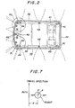
- the robot comprises a body 30 which is substantially entirely surrounded by a front bumper 31, side bumpers 32 and 33, and a rear bumber 34, each carrying the touch sensor 5 therewith.
- An obstruction is sensed by the contact of any one of the bumpers 31-34 therewith.
- the obstruction sensors 4 comprise, in Figure 2, supersonic wave sensors 4A mounted in the central and opposite corners of the front end of the robot body 30, supersonic wave sensors 4B on opposite sides, and supersonic wave sensors 4C at opposite corners of the rear end. All the supersonic wave sensors 4A, 4B and 4C operate in the manner previously described.
- the supersonic wave sensors 4A and 4C are capable of sensing obstructions before the touch sensors 5 come into contact therewith.
- the touch sensors 5 will sense them only if the bumpers 31-34 lightly touch them.
- the robot body 30 is freely movable on a floor by means of a front wheel 40 and a pair of rear wheels 41 and 42, which are the drive wheels. While the robot travels on a floor, two rotary sweepers 43 and 44 mounted on the front underside of the body 30 clean the floor.
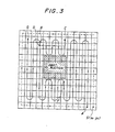
- the control console 16 of the robot is manipulated to set up a teaching mode and, then, the robot is led to a start position (S) shown in Figure 3 by use of the remote control transmit unit 17 and receive unit 18.
- a set button in the control console 16 is depressed to set a start point (x o , y o ) in the two-dimensional coordinates and a reference 8 0 of travelling directions.
- the CPU 9 of the control circuit 6 sequentially stores in the storage 10 instantaneous positions (x, y) and travelling directions 8 of the robot which are supplied thereto from the position identification means 3, whereby the robot studies the boundary of the expected range of movement.
- the boundary is stored in a map in the two-dimensional coordinates and in the form of blocks which are divided at each unit distance along the x- and y-axes.
- the robot is brought to the start point or to a point A adjacent to the start point and, then, the control console 16 is operated to switch the operation mode from the teaching mode to an unmanned running mode. This causes the control circuit 6 to deliver a drive signal to the drive 12 so that the robot begins an automatic run.
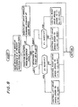
- the automatic run of the robot is effected as follows controlled by the CPU 9.
- the robot advances straight ahead over the blocks in a column which extends along the y-axis in the map.
- the blocks which the robot has travelled are sequentially stored in the storage 10.
- the supersonic wave sensors 4B on the sides of the robot continuously watch the neighborhood to see if any obstruction is present at the right or left of the running column. If any obstruction is present, it is stored in the storage 10 and, if not, the blocks are stored as clear blocks in the storage 10.
- the straight run is sequentially repeated thereafter so that the travelled blocks increased in number one column at a time and, at the same time, the clear blocks stored in the storage 10 are successively erased.
- the sensor 4A at the front end of the robot senses an obstruction head at a point F
- the robot is turned toward the next non-travelled column of blocks as when the boundary is identified.
- the block in which the sensor 4A has sensed the obstruction is stored in the storage 10.
- the robot moves back and forth between the obstruction and the boundary while sensing the obstruction and without hitting thereagainst.
- the robot drives forward along the column until the boundary is identified.
- the robot finds clear blocks at opposite sides thereof.
- the robot is caused to turn in the opposite direction after reaching the boundary, thereby running in a non-travelled region of the floor at the rear of the obstruction.
- the point B at which the robot has turned this time is stored in the storage 10 in preparation for a return to the original position as will be described.
- the robot sequentially sweeps the non-travelled region in the manner described, repeatedly turning in the direction of the columns.
- the robot identifies that a travelled block is present in the direction of the next turn. Then, the robot decides that it has fully covered the non-travelled region, returns straight to the point B along the transverse train or row of blocks, and then starts another run along the columns from a point D which is in a block next to the block B.
- the robot When the robot reaches a point G after the procedure described above, it ends the movement determining that no region in the taught range of movement is left unswept. To see if any range is left unswept, the robot compares the travelled region and the obstruction region stored in the storage 10.
- the robot immediately turns to the unswept area as soon as an obstruction is cleared.
- the robot may be programmed to move to the upswept area after completing the travel throughout the region inside the boundary.
- the sweepers 43 and 44 are rotated during the travel of the robot to effectively clean all over the predetermined range of the floor.
- the operation of the robot control system in accordance with the present invention will be further discussed in conjunction with the pattern shown in Figure 5.
- the operation for the alternative sweeping pattern starts with teaching the robot a predetermined range of travel (surrounded by a dotted line in Figure 5). Thereafter, the robot is returned to a start point S to begin an automatic run. While repeating reciprocal movement in the manner described, the robot senses a first obstruction (1) at a point H so that it sequentially shifts to the following columns turning at the point H. As the robot further advances column by column until sensing a projecting wall as illustrated, it stores the specific column at a point J and then repeatedly moves back and forth along the successive columns.
- the robot After sensing a second obstruction (2), the robot runs back and forth down to a point K avoiding the obstruction (2), as has been the case with the pattern shown in Figure 3. From the point K, the robot returns to the point J in the stored specific column traversing the swept columns. At the point J, the robot is redirected to follow the boundary of the predetermined range. As soon as the robot clears the protruding wall, it steers itself into a column which is the extension of the column with the point J, and then resumes a straight travel. At this instant, the robot advances into a new non-travelled area updating (clearing) the stored column. At a point L, the robot enters an area at the back of the obstruction (1) which has been left unswept. Thereafter, the robot shifts from a point M back to the point L across the swept columns so as to start a reciprocal movement again. At a point N, the robot completes the whole movement determining that it has thoroughly swept the taught range of movement.
- the robot may become dislocated from a predetermined or reference path as shown in Figure 7 due to slippage of the drive wheels 41 and 42, errors in the operation of the motors 13 and 14, etc.
- the deviation of the actual path of travel from the reference path is compensated for by the following control.
- the other condition, d+tan 8 ⁇ 0 represents a situation in which the angle 8 is negative and the robot is directed toward the path at a large angle.
- the actual path of the robot is controlled to the reference path if dislocated therefrom, that is, the position of the robot is corrected.
- Teaching the robot a desired range of movement may be implemented by the supersonic wave sensors 4A, 4B and 4C and the touch sensors 5 which are mounted on the robot itself, instead of the remote control transmit and receive units.
- Some of the supersonic wave sensors 4A, 4B and 4C are capable of identifying short and medium ranges and the others, long ranges. Such self-teaching with the various sensors is optimum for cleaning, for example, the floor of a room which is surrounded by walls; the robot will make one round automatically along the walls of the room by sensing the walls with the sensors.
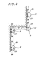
- FIG. 9 An example of the travelling pattern along walls is shown in Figure 9.
- the robot is controlled on the basis of outputs of the medium range sensors S 2 and So.
- the rotation of the drive wheel remote from the wall is decelerated or stopped to correct the orientation of the robot away from the wall.
- the robot is allowed to run straight without any further compensation. If the robot is positioned too far from the wall, the output of either one of the medium range sensors S : and S 3 will disappearto cause the control circuit to decelerate or stop the movement of the drive wheel closer to the wall, thereby bringing the robot closer to the wall.
- the robot As the robot reaches the point b where the front sensor S, senses the wall ahead, it once stops its movement and then moves backward a predeter- - mined distance. Then, the robot rotates clockwise as viewed in Figure 9 over a predetermined angle 0 (with the right drive wheel stopped and the left drive wheel rotated for a predetermined period of time), thereafter resuming the straight run.
- the front sensor S is turned on again, the above procedure is repeated to further rotate the robot so that, eventually, the robot attains a position parallel to the wall. Thereafter, the robot runs straight from the point b to the next point c.
- the medium range sensors S 2 and S 3 no longer sense the wall while only the long range sensor S 4 senses it. Hence, the robot is caused to rotate counterclockwise at that point as viewed in Figure 9. As soon as the medium range sensors S 2 and S 3 come to sense the wall again, the robot is allowed to run a straight path along the wall.
Description
- The present invention relates to a control system for an unmanned, mobile robot which has drive wheels to be capable of automatically travelling along a predetermined path.
- A mobile robot designed for unmanned movement is sometimes used for cleaning the floors of buildings. Such a robot may be equipped with a vacuum cleaner and/or sweepers to clean a range of a floor which it travels. Prior art system proposed for controlling the travel of the mobile robot includes one which lays guide cables along a predetermined path of travel of the robot so as to generate an electromagnetic wave. The robot will be guided by the cables while sensing the magnetic field by means of a sensor. Another prior art control system used optical marks or tapes which are located along the path of travel so that the robot may follow the path sensing the marks or tapes.
- The prior art control systems described so far commonly achieved unmanned robot movement along a predetermined pattern by means of guide means in one form or another. A problem encountered with such guide means type systems is that troublesome work is required for setting and changing a running pattern. Another problem is that the installation of such guide means on floors is undesirable for some kind of buildings. Additionally, where an obstruction is positioned in a predetermined path, the robot cannot travel any further unless it is removed.
- In the prior art in accordance with US-A-3 750 833 and US-A-3 713 505, a control system for a mobile robot is disclosed for causing the robot to automatically run along a predetermined path in a selected direction and at a selected speed by controlling rotations of the drive wheels of the robot. The control system comprises obstruction sensor means for sensing an obstruction to generate an obstruction signal, said obstruction sensor means being mounted on a front end and on a rear side of the robot with respect to the intended direction of travel of the robot.
- Further storage means are provided to store signals generated by the sensing means for determining distance of lateral movement required to detour around an obstacle, in other words, it stores relative position of the vehicle to the obstacle in lateral direction. Operation means are also provided to regulate the driving direction of the robot drive motor when the robot hits an obstacle. When the robot is shifted laterally, it again starts with a forward movement. This kind of control system has disadvantages in several aspects. First, the system can only travel over areas which are surrounded by a wall. Further, the system is not able to distinguish the travel region so that the system goes twice over the same region which in particular makes the travel distance to cover the area behind an obstacle very long.
- In the FR-A-2 526 181 a control system for a robot is disclosed to which the precharacterising clause of
Claim 1 refers. - The system disclosed in said FR document is intended to serve a plurality of tool machines in a flexible chain intended to machine and/or assembly work pieces which are fed unmachined and unassembled at a supply position and evacuated finished at an output position. In addition to the features mentioned in the precharacterising clause of
Claim 1, said known system comprises a central operative means intended to receive from a distance encoder a signal representative of the distance effectively travelled by the robot and from a direction encoder a signal representative of the directional along which the robot effectively travels. The system calculates from said actual distance and direction signals the corresponding effective actual position of said robot. The central operative means being further intended to receive from said storage means the signals representative of said predetermined path to be travelled which has been stored and are updated in the map of the storage means during a previous teaching mode operation and to command a driving motor and a steering organ in such a way that said calculated effective actual position of the robot matches at any instance the position the robot shall have according to said predetermined path stored in said map of said storage means. - It is the object of the present invention as claimed, to provide a control system for a mobile robot which makes it possible for the robot to study and store a range which is to be moved and, during a travel, employs its own decision while determining a travel pattern in the specific range in response to varying conditions and which allows the robot to travel in a range assigned thereto without hitting against possible obstructions and thoroughly in the rest of a specific range.
- A control system for a mobile robot of the present invention causes the robot to automatically run along a predetermined path and in a selected direction at a selected speed by controlling rotations of right and left wheels thereof independently of each other. The control system comprises position identification means for sensing a distance travelled by the robot and a change in a direction of travel of the robot, calculating a position of the robot in two-dimensional coordinates in response to the sensed distance and the sensed change in direction, and generating a position signal representative of the robot position. Obstruction sensor means senses an obstruction to generate an obstruction signal. The obstruction sensor means are mounted on a front end and both sides of the robot with respect to an intended direction of travel of the robot. Storage means stores a map consisting of a number of unit blocks which are defined by parallel columns and parallel rows in the two-dimensional coordinates. Teaching means causes the robot to make a round along a boundary of a range to be travelled by the robot, so that the range is stored in the map of the storage means in response to the position signal output from the position identification means. First operation means causes the robot to sequentially move back and forth along one of the columns and rows of the map in the range stored in the map, while sequentially shifting the robot to one of the subsequent columns and rows. Second operation means shifts the robot to one of the next column and the next row in response to detection of an obstruction by turning the robot at a position where the obstruction is sensed. Non-travelled region discriminating means discriminates a non-travelled region by reading out a travelled region out of the storage means and comparing the travelled region with the range to be travelled. Third operation means returns the robot to a non-travelled region to cause the robot to resume reciprocation when the non-travelled region is present on an extension of a travelled column, at one of an instant when an obstruction ahead the robot disappears and an instant when the travel of the robot un the range to be travelled is completed. End-of-travel discriminating means discriminates completion of the travel when a non-travelled region is eliminated in the range to be travelled except for an obstruction.
- The above and other objects, features and advantages of the present invention will become apparent from the following detailed description taken with the accompanying drawing.
-
- Figure 1 is a block diagram of a robot control system embodying the present invention;
- Figure 2 is a schematic plan view of a robot body in accordance with the present invention;
- Figure 3 is a diagram showing a first example of running patterns of the robot in accordance with the present invention;
- Figure 4 is a flowchart demonstrating a control for effecting the run shown in Figure 3;
- Figure 5 is a diagram showing a second example of the robot running patterns;
- Figure 6 is a flowchart demonstrating a control for effecting the run shown in Figure 5;
- Figure 7 is a diagram explanatory of a deviation of the robot from a predetermined straight path;
- Figure 8 is a flowchart representing a control for compensating for the deviation shown in Figure 7; and
- Figure 9 is a diagram showing an example of a self-teaching travel of the robot.
- While the control system for a mobile robot of the present invention is susceptible of numerous physical embodiments, depending upon the environment and requirements of use, a substantial number of the herein shown and described embodiment have been made, tested and used, and all have performed in an eminently satisfactory manner.
- Referring to Figure 1 of the drawing,
reference numeral 1 designates a distance sensor for producing a pulse signal which is proportional to a distance travelled by the mobile robot, e.g. number of rotations of drive wheels. Adirection sensor 2, such as a gas rate gyro, is sensitive to a change in the travelling direction of the robot. The pulse signal output from thedistance sensor 1 and the output of the direction sensor are supplied to position identification means 3. The position identification means 3 is constructed to measure a distance travelled by the robot by counting incoming pulses from thedistance sensor 1 and to identify a moving direction of the robot from the output of thedirection sensor 2, thereby identifying by operation instantaneous positions of the robot in two-dimensional coordinates for each unit travel distance. Obstruction sensors 4 are mounted on the front, opposite sides and back of the robot with respect to a direction of movement of the robot. Each of the obstruction sensors 4 is adapted to sense a wall, column or like obstruction and a distance to the obstruction by emitting a supersonic wave and receiving the reflection. Also mounted on the robot are touch sensors 5 which locate obstructions by mechanical contact therewith, independently of the obstruction sensors 4. The outputs of the sensors 4 and 5 are routed via an amplifier 7 and an input/output I/O)port 8D to acontrol circuit 6, which comprises a microprocessor. Also, the output of the position identification means 3 is applied to thecontrol circuit 6 via an I/O port 8A. - The
control circuit 6 comprises a central operational circuitry (CPU) 9, and astorage 10 made up of a read only memory (ROM) and a random access memory (RAM). Thecontrol circuit 6 further comnprises an oscillator 11A for generating clock pulses, and an interrupt controller 11 B. As will be described, theCPU 9 delivers a drive signal to adrive signal 12 via an I/O port 8C in order to reversibly control the rotation of drive motors (servo motors or stepping motors) 13 and 14, which are respectively associated with right and left drive wheels of the robot. At the same time, thecontrol 6 controls the rotation of adrive motor 15 for cleaning sweepers which are mounted on the robot. Acontrol console 16 is accessible for selectively turning on and off a system power source, switching a running mode, setting a start position, adjusting a sensitivity of thedirection sensor 2, etc. In order to teach the robot a boundary of a travel range assigned thereto, a command may be applied to thedrive 12 by interruption with priority on a radio control basis. This is effected by a remote control transmitunit 17 and a receiveunit 18. The outputs of thecontrol console 16 and remote control receiveunit 18 are routed also to thecontrol circuit 6 via an I/0 port 8B. - Referring to Figure 2, a practical construction of the mobile robot is shown in a schematic plan view. As shown, the robot comprises a
body 30 which is substantially entirely surrounded by afront bumper 31,side bumpers rear bumber 34, each carrying the touch sensor 5 therewith. An obstruction is sensed by the contact of any one of the bumpers 31-34 therewith. The obstruction sensors 4 comprise, in Figure 2,supersonic wave sensors 4A mounted in the central and opposite corners of the front end of therobot body 30,supersonic wave sensors 4B on opposite sides, andsupersonic wave sensors 4C at opposite corners of the rear end. All thesupersonic wave sensors - Usually, the
supersonic wave sensors sensors robot body 30 is freely movable on a floor by means of afront wheel 40 and a pair ofrear wheels rotary sweepers body 30 clean the floor. - In conjunction with a robot having the above construction, characteristic part of the present invention will be further described with reference to Figures 3 and 4.
- Assuming a range shown in Figure 3 which the robot is to sweep. First, the
control console 16 of the robot is manipulated to set up a teaching mode and, then, the robot is led to a start position (S) shown in Figure 3 by use of the remote control transmitunit 17 and receiveunit 18. At the start position, a set button in thecontrol console 16 is depressed to set a start point (xo, yo) in the two-dimensional coordinates and a reference 80 of travelling directions. - As the teaching for the robot along a predetermined course is started as indicated by a dotted line in Figure 3 by means of the transmit
unit 17 and receiveunit 18, theCPU 9 of thecontrol circuit 6 sequentially stores in thestorage 10 instantaneous positions (x, y) and travelling directions 8 of the robot which are supplied thereto from the position identification means 3, whereby the robot studies the boundary of the expected range of movement. After the travel of the robot along the teaching course, the boundary is stored in a map in the two-dimensional coordinates and in the form of blocks which are divided at each unit distance along the x- and y-axes. Next, the robot is brought to the start point or to a point A adjacent to the start point and, then, thecontrol console 16 is operated to switch the operation mode from the teaching mode to an unmanned running mode. This causes thecontrol circuit 6 to deliver a drive signal to thedrive 12 so that the robot begins an automatic run. - The automatic run of the robot is effected as follows controlled by the
CPU 9. - Initially, the robot advances straight ahead over the blocks in a column which extends along the y-axis in the map. At this instant, the blocks which the robot has travelled are sequentially stored in the
storage 10. As soon as the robot reaches the boundary which is identified by the position identification means 3, it is turned leftwardly from that position toward a non-travelled column of blocks (extending along the y-axis). While the robot moves the new column of blocks, thesupersonic wave sensors 4B on the sides of the robot continuously watch the neighborhood to see if any obstruction is present at the right or left of the running column. If any obstruction is present, it is stored in thestorage 10 and, if not, the blocks are stored as clear blocks in thestorage 10. The straight run is sequentially repeated thereafter so that the travelled blocks increased in number one column at a time and, at the same time, the clear blocks stored in thestorage 10 are successively erased. When thesensor 4A at the front end of the robot senses an obstruction head at a point F, the robot is turned toward the next non-travelled column of blocks as when the boundary is identified. Simultaneously, the block in which thesensor 4A has sensed the obstruction is stored in thestorage 10. - In the manner described, the robot moves back and forth between the obstruction and the boundary while sensing the obstruction and without hitting thereagainst. When the robot comes to find no obstruction ahead, it drives forward along the column until the boundary is identified. As soon as the robot runs past the adjacent wall of the obstruction, it finds clear blocks at opposite sides thereof. This time, the robot is caused to turn in the opposite direction after reaching the boundary, thereby running in a non-travelled region of the floor at the rear of the obstruction. The point B at which the robot has turned this time is stored in the
storage 10 in preparation for a return to the original position as will be described. The robot sequentially sweeps the non-travelled region in the manner described, repeatedly turning in the direction of the columns. At a point C, the robot identifies that a travelled block is present in the direction of the next turn. Then, the robot decides that it has fully covered the non-travelled region, returns straight to the point B along the transverse train or row of blocks, and then starts another run along the columns from a point D which is in a block next to the block B. - When the robot reaches a point G after the procedure described above, it ends the movement determining that no region in the taught range of movement is left unswept. To see if any range is left unswept, the robot compares the travelled region and the obstruction region stored in the
storage 10. - In the illustrative embodiment described above, if any area is left unswept un the columns which the robot has travelled, the robot immediately turns to the unswept area as soon as an obstruction is cleared. Alternatively, the robot may be programmed to move to the upswept area after completing the travel throughout the region inside the boundary. In any case, the
sweepers - The operation of the robot control system in accordance with the present invention will be further discussed in conjunction with the pattern shown in Figure 5. The operation for the alternative sweeping pattern starts with teaching the robot a predetermined range of travel (surrounded by a dotted line in Figure 5). Thereafter, the robot is returned to a start point S to begin an automatic run. While repeating reciprocal movement in the manner described, the robot senses a first obstruction (1) at a point H so that it sequentially shifts to the following columns turning at the point H. As the robot further advances column by column until sensing a projecting wall as illustrated, it stores the specific column at a point J and then repeatedly moves back and forth along the successive columns. After sensing a second obstruction (2), the robot runs back and forth down to a point K avoiding the obstruction (2), as has been the case with the pattern shown in Figure 3. From the point K, the robot returns to the point J in the stored specific column traversing the swept columns. At the point J, the robot is redirected to follow the boundary of the predetermined range. As soon as the robot clears the protruding wall, it steers itself into a column which is the extension of the column with the point J, and then resumes a straight travel. At this instant, the robot advances into a new non-travelled area updating (clearing) the stored column. At a point L, the robot enters an area at the back of the obstruction (1) which has been left unswept. Thereafter, the robot shifts from a point M back to the point L across the swept columns so as to start a reciprocal movement again. At a point N, the robot completes the whole movement determining that it has thoroughly swept the taught range of movement.
- Now, while automatically running in the manner described, the robot may become dislocated from a predetermined or reference path as shown in Figure 7 due to slippage of the
drive wheels motors - A routine for the control is shown in Figure 8 and will hereinafter be discussed with reference to Figure 7 as well.
- As shown in Figure 7, assume that the robot is deviated to the right from the reference path by a distance d with respect to the travelling direction of the robot, and that it is misoriented by an angle 8 relative to the reference path. Then, that the deviation of the robot is to the right of the reference path is determined. Also, whether the sign of d+tan 8 is positive or negative is determined by operation. Let it be assumed that d+tan 6 is either d+tan θ≧0 or d+tan 8<0.
- In the first-mentioned condition, d+tan6?0, the distance d is large, or the
angle 0 is relatively small, or the orientation of the robot lies in the positive angular range. Then, the rotation speed V of the left drive wheel is controlled to be V=Vo-(d+tan 6) (where the minimum value of V is assumed to be Vo), while the rotation speed of the right drive wheel is kept at Vo, whereby the robot is caused to make a leftward turn or rotate leftwardly about an axis thereof. - The other condition, d+tan 8<0 represents a situation in which the angle 8 is negative and the robot is directed toward the path at a large angle. In this case, while the rotation of the left drive wheel is maintained the same, the rotation speed V of the right drive wheel is controlled to be V=Vo+(d+tan 0), thereby turning or rotating the robot to the right.
- In this manner, the actual path of the robot is controlled to the reference path if dislocated therefrom, that is, the position of the robot is corrected.
- The compensation effected for rightward deviation of the actual robot path from the reference ' path as described similarly applies to leftward deviation of the robot, except for the reversal of angles and that of the control over the right and left drive wheels.
- Due to the use of a tan function as a compensation term for the angle θ, so long as MAX in the relation -MAX<tan 8<MAX is sufficiently large, there exist a position and an angle where d+tan θ=0 holds, even if the deviation d from the path is substantial. At such a specific point, the right and left drive wheels of the robot are equal in velocity and they approach the path at an angle to the path which becomes closer to the right angle as the distance d increases and decreases with the decrease in the distance d. Stated another way, the orientation of the robot is compensated sharply when the distance d is large and the compensation is slowed down as the distance d becomes smaller. This insures smooth compensation of the orientation of the robot without hunting or the like due to excessive controls during the compensation. If desired, the term d may be multiplied by a positive constant a and the term tan 8 by a positive constant β so that any desired path compensation characteristic is established up to the point where ad+βtanθ=0 holds, that is, the point where the robot advances straight with the right and left drive wheels running at an equal speed.
- Teaching the robot a desired range of movement may be implemented by the
supersonic wave sensors supersonic wave sensors - An example of the travelling pattern along walls is shown in Figure 9. During the straight travel from a point a to a point b, the robot is controlled on the basis of outputs of the medium range sensors S2 and So. When the robot is too close to the wall, the rotation of the drive wheel remote from the wall is decelerated or stopped to correct the orientation of the robot away from the wall. As the outputs of the two medium range sensors S2 and S3 coincide with each other, the robot is allowed to run straight without any further compensation. If the robot is positioned too far from the wall, the output of either one of the medium range sensors S: and S3 will disappearto cause the control circuit to decelerate or stop the movement of the drive wheel closer to the wall, thereby bringing the robot closer to the wall.
- As the robot reaches the point b where the front sensor S, senses the wall ahead, it once stops its movement and then moves backward a predeter- - mined distance. Then, the robot rotates clockwise as viewed in Figure 9 over a predetermined angle 0 (with the right drive wheel stopped and the left drive wheel rotated for a predetermined period of time), thereafter resuming the straight run. When the front sensor S, is turned on again, the above procedure is repeated to further rotate the robot so that, eventually, the robot attains a position parallel to the wall. Thereafter, the robot runs straight from the point b to the next point c.
- As the robot moves past the point c, the medium range sensors S2 and S3 no longer sense the wall while only the long range sensor S4 senses it. Hence, the robot is caused to rotate counterclockwise at that point as viewed in Figure 9. As soon as the medium range sensors S2 and S3 come to sense the wall again, the robot is allowed to run a straight path along the wall.
- While the robot in Figure 9 is assumed to travel along walls which are commonly located to the left thereof with respect to the direction of travel, the same control applies to the case wherein the walls are located to the right of the robot, except for the reversal of the rotating directions of the robot.
- Various modifications will become possible for those skilled in the art after receiving the teachings of the present disclosure without departing from the scope thereof.
Claims (4)
in that the map consists of a number of unit blocks which are defined by parallel columns and parallel rows in the two-dimensional co-ordinates and in that the control system comprises:
Priority Applications (1)
| Application Number | Priority Date | Filing Date | Title |
|---|---|---|---|
| AT84100065T ATE44322T1 (en) | 1983-10-26 | 1984-01-04 | CONTROL SYSTEM FOR A MOVABLE ROBOT. |
Applications Claiming Priority (4)
| Application Number | Priority Date | Filing Date | Title |
|---|---|---|---|
| JP58200360A JPS6093522A (en) | 1983-10-26 | 1983-10-26 | Controller of moving robot |
| JP200360/83 | 1983-10-26 | ||
| JP201652/83 | 1983-10-27 | ||
| JP58201652A JPS6093524A (en) | 1983-10-27 | 1983-10-27 | Controller of moving robot |
Publications (2)
| Publication Number | Publication Date |
|---|---|
| EP0142594A1 EP0142594A1 (en) | 1985-05-29 |
| EP0142594B1 true EP0142594B1 (en) | 1989-06-28 |
Family
ID=26512137
Family Applications (1)
| Application Number | Title | Priority Date | Filing Date |
|---|---|---|---|
| EP84100065A Expired EP0142594B1 (en) | 1983-10-26 | 1984-01-04 | Control system for mobile robot |
Country Status (4)
| Country | Link |
|---|---|
| US (1) | US4674048A (en) |
| EP (1) | EP0142594B1 (en) |
| CA (1) | CA1217836A (en) |
| DE (1) | DE3478824D1 (en) |
Cited By (7)
| Publication number | Priority date | Publication date | Assignee | Title |
|---|---|---|---|---|
| DE4307125A1 (en) * | 1992-03-09 | 1993-09-16 | Gold Star Co | Automatic floor cleaning method - using sensors to determine relative wall positions for real-time calculation of nested cleaning contours |
| DE4340771A1 (en) * | 1993-06-08 | 1994-12-15 | Samsung Electronics Co Ltd | Automatic cleaning device |
| DE19916427B4 (en) * | 1998-07-31 | 2004-07-01 | Sommer, Volker, Dr.-Ing. | Household robots for automatic vacuuming of floor surfaces |
| US8303720B2 (en) | 2006-04-04 | 2012-11-06 | Maasland N.V. | Apparatus for and a method for cleaning the floor of an accommodation of an animal |
| US8543276B2 (en) | 2006-04-18 | 2013-09-24 | Lely Patent N.V. | Unmanned autonomous vehicle for displacing feed |
| US8612083B2 (en) | 2010-05-12 | 2013-12-17 | Lely Patent N.V. | Vehicle for displacing feed |
| US8694191B2 (en) | 2006-04-18 | 2014-04-08 | Maasland N.V. | Unmanned autonomous vehicle for displacing feed |
Families Citing this family (250)
| Publication number | Priority date | Publication date | Assignee | Title |
|---|---|---|---|---|
| NL8500529A (en) * | 1985-02-25 | 1986-09-16 | Ind Contractors Holland Bv | SYSTEM FOR DETERMINING THE POSITION OF A VEHICLE NOT BONDED TO A FIXED TRACK. |
| US5280431A (en) * | 1985-08-30 | 1994-01-18 | Texas Instruments Incorporated | Method for controlling the movements of a mobile robot in a multiple node factory |
| JPH0785205B2 (en) * | 1985-08-30 | 1995-09-13 | テキサス インスツルメンツインコ−ポレイテツド | Fail-safe braking system for multi-wheel vehicles whose steering is controlled by a motor |
| AU598758B2 (en) * | 1985-10-15 | 1990-07-05 | Hans-Reinhard Knepper | Automatic steering control for a vehicle |
| NO864109L (en) * | 1985-10-17 | 1987-04-21 | Knepper Hans Reinhard | PROCEDURE FOR AUTOMATIC LINING OF AUTOMATIC FLOOR CLEANING MACHINES AND FLOOR CLEANING MACHINE FOR PERFORMING THE PROCEDURE. |
| US4809178A (en) * | 1986-05-22 | 1989-02-28 | Kabushiki Kaisha Toyota Chuo Kenkyusho | Obstacle data processing system for unmanned vehicle |
| FR2610428B1 (en) * | 1986-12-09 | 1997-01-03 | Kubota Ltd | CONTROL SYSTEM FOR A SELF-PROPELLED OPERATING VEHICLE, PARTICULARLY FOR THE SPRAYING OF CHEMICALS INTENDED FOR AGRICULTURAL PROCESSING |
| US5377106A (en) * | 1987-03-24 | 1994-12-27 | Fraunhofer Gesellschaft Zur Foerderung Der Angewandten Forschung E.V. | Process for navigating an unmanned vehicle and a vehicle for the same |
| DE3709627A1 (en) * | 1987-03-24 | 1988-10-13 | Fraunhofer Ges Forschung | SELF-DRIVING VEHICLE |
| US4982329A (en) * | 1987-06-27 | 1991-01-01 | Shinko Electric Co., Ltd. | Self-contained unmanned vehicle |
| FR2619230B1 (en) * | 1987-08-07 | 1990-01-05 | Mareau Dominique | VEHICLE CONTROL AND GUIDANCE SYSTEM WITH AUTOMATIC GYROSCOPIC EQUIPMENT, SUCH AS A LAWN MOWER OR THE LIKE. |
| JPS6488716A (en) * | 1987-09-30 | 1989-04-03 | Komatsu Mfg Co Ltd | Automatic driving device for traveling vehicle |
| US6324476B1 (en) * | 1987-11-20 | 2001-11-27 | Philips Electronicsnorth America Corporation | Method and apparatus for identifying or controlling travel to a rendezvous |
| US5220497A (en) * | 1987-11-20 | 1993-06-15 | North American Philips Corp. | Method and apparatus for controlling high speed vehicles |
| US4949277A (en) * | 1988-03-09 | 1990-08-14 | North American Philips Corporation | Differential budding: method and apparatus for path planning with moving obstacles and goals |
| US5083256A (en) * | 1988-03-09 | 1992-01-21 | North American Philips Corporation | Path planning with transition changes |
| US5808887A (en) * | 1987-11-20 | 1998-09-15 | Philips Electronics North America Corporation | Animation of path planning |
| DE3853616T2 (en) * | 1987-11-20 | 1995-11-30 | Philips Electronics Nv | Method and device for route planning. |
| US5870303A (en) * | 1987-11-20 | 1999-02-09 | Philips Electronics North America Corporation | Method and apparatus for controlling maneuvers of a vehicle |
| FR2624633B1 (en) * | 1987-12-14 | 1992-09-11 | Sgs Thomson Microelectronics | ROBOT PROGRAMMING SYSTEM |
| JPH01180010A (en) * | 1988-01-08 | 1989-07-18 | Sanyo Electric Co Ltd | Moving vehicle |
| US5047916A (en) * | 1988-03-25 | 1991-09-10 | Kabushiki Kaisha Toshiba | Method and apparatus of free space enumeration for collision avoidance |
| GB2218538B (en) * | 1988-05-13 | 1992-09-16 | Gen Electric Co Plc | Automated vehicle control |
| US4986280A (en) * | 1988-07-20 | 1991-01-22 | Arthur D. Little, Inc. | Hand position/measurement control system |
| JP2717810B2 (en) * | 1988-08-16 | 1998-02-25 | 本田技研工業株式会社 | Self-propelled work robot |
| US4962453A (en) * | 1989-02-07 | 1990-10-09 | Transitions Research Corporation | Autonomous vehicle for working on a surface and method of controlling same |
| US5179329A (en) * | 1989-04-25 | 1993-01-12 | Shinko Electric Co., Ltd. | Travel control method, travel control device, and mobile robot for mobile robot systems |
| JP2815606B2 (en) * | 1989-04-25 | 1998-10-27 | 株式会社トキメック | Control method of concrete floor finishing robot |
| US5006988A (en) * | 1989-04-28 | 1991-04-09 | University Of Michigan | Obstacle-avoiding navigation system |
| JPH0313611A (en) * | 1989-06-07 | 1991-01-22 | Toshiba Corp | Automatic cleaner |
| FR2648581A1 (en) * | 1989-06-16 | 1990-12-21 | Commissariat Energie Atomique | METHOD FOR CREATING AND TRACKING A TRACK FOR A VEHICLE SUCH AS A ROBOT |
| US5050771A (en) * | 1989-07-31 | 1991-09-24 | Field Control Systems, Inc. | Repeatable pattern field spraying control |
| SE465487B (en) * | 1989-12-07 | 1991-09-16 | Goeran Lennart Bergqvist | PROCEDURE AND SYSTEM FOR NAVIGATION OF UNDEMANDED VEHICLES |
| US5610815A (en) * | 1989-12-11 | 1997-03-11 | Caterpillar Inc. | Integrated vehicle positioning and navigation system, apparatus and method |
| WO1991009375A1 (en) * | 1989-12-11 | 1991-06-27 | Caterpillar Inc. | Integrated vehicle positioning and navigation system, apparatus and method |
| US5390125A (en) * | 1990-02-05 | 1995-02-14 | Caterpillar Inc. | Vehicle position determination system and method |
| FR2657975B1 (en) * | 1990-02-08 | 1996-08-09 | Commissariat Energie Atomique | METHOD FOR CREATING OR RETURNING A ROUTE BY A VEHICLE AND VEHICLE ADAPTED TO THIS PROCESS. |
| FR2660454B1 (en) * | 1990-03-27 | 1996-08-09 | Commissariat Energie Atomique | METHOD FOR DRIVING A VEHICLE SUCH AS A WHEELCHAIR FOR A PERSON WITH A DISABILITY. |
| JP2792210B2 (en) * | 1990-07-03 | 1998-09-03 | 富士電機株式会社 | Control method and control device for automatic guided vehicle |
| US5105368A (en) * | 1990-08-01 | 1992-04-14 | At&T Bell Laboratories | Method for improving robot accuracy |
| US5307271A (en) * | 1990-09-28 | 1994-04-26 | The United States Of America As Represented By The Secretary Of The Navy | Reflexive teleoperated control system for a remotely controlled vehicle |
| KR930000081B1 (en) * | 1990-12-07 | 1993-01-08 | 주식회사 금성사 | Cleansing method of electric vacuum cleaner |
| US5227973A (en) * | 1991-02-26 | 1993-07-13 | Siemens Corporate Research, Inc. | Control arbitration system for a mobile robot vehicle |
| DE4108939A1 (en) * | 1991-03-19 | 1992-09-24 | Bodenseewerk Geraetetech | METHOD FOR CALIBRATING HIGH-PRECISION ROBOTS |
| US5321614A (en) * | 1991-06-06 | 1994-06-14 | Ashworth Guy T D | Navigational control apparatus and method for autonomus vehicles |
| EP0546633A2 (en) * | 1991-12-11 | 1993-06-16 | Koninklijke Philips Electronics N.V. | Path planning in an uncertain environment |
| US8352400B2 (en) | 1991-12-23 | 2013-01-08 | Hoffberg Steven M | Adaptive pattern recognition based controller apparatus and method and human-factored interface therefore |
| US10361802B1 (en) | 1999-02-01 | 2019-07-23 | Blanding Hovenweep, Llc | Adaptive pattern recognition based control system and method |
| US5279672A (en) * | 1992-06-29 | 1994-01-18 | Windsor Industries, Inc. | Automatic controlled cleaning machine |
| FR2697098B1 (en) * | 1992-10-07 | 1995-01-06 | Sn Eno | Method for controlling the movement of an autonomous electric machine with random displacement, and suitable electric machine. |
| US5548511A (en) * | 1992-10-29 | 1996-08-20 | White Consolidated Industries, Inc. | Method for controlling self-running cleaning apparatus |
| US5416321A (en) * | 1993-04-08 | 1995-05-16 | Coleman Research Corporation | Integrated apparatus for mapping and characterizing the chemical composition of surfaces |
| US5402344A (en) * | 1993-08-23 | 1995-03-28 | Martin Marietta Energy Systems, Inc. | Method for controlling a vehicle with two or more independently steered wheels |
| SE502834C2 (en) * | 1994-03-29 | 1996-01-29 | Electrolux Ab | Method and apparatus for detecting obstacles in self-propelled apparatus |
| JPH07319542A (en) * | 1994-05-30 | 1995-12-08 | Minolta Co Ltd | Self-traveling work wagon |
| SE514791C2 (en) * | 1994-06-06 | 2001-04-23 | Electrolux Ab | Improved method for locating lighthouses in self-propelled equipment |
| IL113913A (en) * | 1995-05-30 | 2000-02-29 | Friendly Machines Ltd | Navigation method and system |
| US6830120B1 (en) * | 1996-01-25 | 2004-12-14 | Penguin Wax Co., Ltd. | Floor working machine with a working implement mounted on a self-propelled vehicle for acting on floor |
| US5833144A (en) * | 1996-06-17 | 1998-11-10 | Patchen, Inc. | High speed solenoid valve cartridge for spraying an agricultural liquid in a field |
| US5763873A (en) * | 1996-08-28 | 1998-06-09 | Patchen, Inc. | Photodetector circuit for an electronic sprayer |
| US5789741A (en) * | 1996-10-31 | 1998-08-04 | Patchen, Inc. | Detecting plants in a field by detecting a change in slope in a reflectance characteristic |
| US5809440A (en) * | 1997-02-27 | 1998-09-15 | Patchen, Inc. | Agricultural implement having multiple agents for mapping fields |
| JPH10240343A (en) * | 1997-02-27 | 1998-09-11 | Minolta Co Ltd | Autonomously traveling vehicle |
| JPH10240342A (en) * | 1997-02-28 | 1998-09-11 | Minolta Co Ltd | Autonomous traveling vehicle |
| JPH10260727A (en) * | 1997-03-21 | 1998-09-29 | Minolta Co Ltd | Automatic traveling working vehicle |
| US7268700B1 (en) | 1998-01-27 | 2007-09-11 | Hoffberg Steven M | Mobile communication device |
| IL124413A (en) * | 1998-05-11 | 2001-05-20 | Friendly Robotics Ltd | System and method for area coverage with an autonomous robot |
| DE19824726C1 (en) * | 1998-06-03 | 1999-08-12 | Braas Gmbh | Method for automatically fixing a roof strip on a carrier structure of the roof of a building |
| US6941199B1 (en) | 1998-07-20 | 2005-09-06 | The Procter & Gamble Company | Robotic system |
| WO2000007492A1 (en) | 1998-07-31 | 2000-02-17 | Volker Sommer | Household robot for the automatic suction of dust from the floor surfaces |
| US6112143A (en) * | 1998-08-06 | 2000-08-29 | Caterpillar Inc. | Method and apparatus for establishing a perimeter defining an area to be traversed by a mobile machine |
| CN1127402C (en) * | 1998-11-30 | 2003-11-12 | 索尼公司 | Robot device and control method thereof |
| US8364136B2 (en) | 1999-02-01 | 2013-01-29 | Steven M Hoffberg | Mobile system, a method of operating mobile system and a non-transitory computer readable medium for a programmable control of a mobile system |
| US7904187B2 (en) | 1999-02-01 | 2011-03-08 | Hoffberg Steven M | Internet appliance system and method |
| US6205381B1 (en) * | 1999-03-26 | 2001-03-20 | Caterpillar Inc. | Method and apparatus for providing autoguidance for multiple agricultural machines |
| NL1012142C2 (en) | 1999-05-25 | 2000-11-28 | Lely Res Holding | Unmanned vehicle for moving manure. |
| JP2001121461A (en) * | 1999-10-26 | 2001-05-08 | Denso Corp | Robot system |
| EP1232424A1 (en) | 1999-11-18 | 2002-08-21 | The Procter & Gamble Company | Home cleaning robot |
| US8412377B2 (en) | 2000-01-24 | 2013-04-02 | Irobot Corporation | Obstacle following sensor scheme for a mobile robot |
| US7155308B2 (en) | 2000-01-24 | 2006-12-26 | Irobot Corporation | Robot obstacle detection system |
| US8788092B2 (en) * | 2000-01-24 | 2014-07-22 | Irobot Corporation | Obstacle following sensor scheme for a mobile robot |
| US6956348B2 (en) | 2004-01-28 | 2005-10-18 | Irobot Corporation | Debris sensor for cleaning apparatus |
| US6481515B1 (en) | 2000-05-30 | 2002-11-19 | The Procter & Gamble Company | Autonomous mobile surface treating apparatus |
| US6496754B2 (en) * | 2000-11-17 | 2002-12-17 | Samsung Kwangju Electronics Co., Ltd. | Mobile robot and course adjusting method thereof |
| US6883201B2 (en) * | 2002-01-03 | 2005-04-26 | Irobot Corporation | Autonomous floor-cleaning robot |
| US6690134B1 (en) | 2001-01-24 | 2004-02-10 | Irobot Corporation | Method and system for robot localization and confinement |
| US7571511B2 (en) | 2002-01-03 | 2009-08-11 | Irobot Corporation | Autonomous floor-cleaning robot |
| US6810305B2 (en) | 2001-02-16 | 2004-10-26 | The Procter & Gamble Company | Obstruction management system for robots |
| SE0100924D0 (en) * | 2001-03-15 | 2001-03-15 | Electrolux Ab | Energy-efficient navigation of an autonomous surface treatment apparatus |
| RU2220643C2 (en) * | 2001-04-18 | 2004-01-10 | Самсунг Гванджу Электроникс Ко., Лтд. | Automatic cleaning apparatus, automatic cleaning system and method for controlling of system (versions) |
| US8396592B2 (en) * | 2001-06-12 | 2013-03-12 | Irobot Corporation | Method and system for multi-mode coverage for an autonomous robot |
| EP2287696B1 (en) * | 2001-06-12 | 2018-01-10 | iRobot Corporation | Method and system for multi-code coverage for an autonomous robot |
| US7429843B2 (en) * | 2001-06-12 | 2008-09-30 | Irobot Corporation | Method and system for multi-mode coverage for an autonomous robot |
| KR100420171B1 (en) * | 2001-08-07 | 2004-03-02 | 삼성광주전자 주식회사 | Robot cleaner and system therewith and method of driving thereof |
| US9128487B2 (en) * | 2001-08-24 | 2015-09-08 | David Wright Young | Apparatus for cleaning lines on a playing surface and associated methods, handle enhancements |
| US7245994B2 (en) * | 2001-08-24 | 2007-07-17 | David Wright Young | Apparatus for cleaning lines on a playing surface and associated methods, enhancements |
| US7957859B2 (en) * | 2001-08-24 | 2011-06-07 | David Wright Young | Methods for cleaning lines on a game playing surface |
| GB0126492D0 (en) * | 2001-11-03 | 2002-01-02 | Dyson Ltd | An autonomous machine |
| US9128486B2 (en) | 2002-01-24 | 2015-09-08 | Irobot Corporation | Navigational control system for a robotic device |
| US7103457B2 (en) * | 2002-03-28 | 2006-09-05 | Dean Technologies, Inc. | Programmable lawn mower |
| US8983776B2 (en) * | 2002-03-28 | 2015-03-17 | Jason A. Dean | Programmable robotic apparatus |
| WO2003083594A1 (en) * | 2002-03-28 | 2003-10-09 | Jason Dean | Programmable lawn mower |
| DK1587725T3 (en) * | 2002-08-30 | 2014-03-17 | Aethon Inc | Trolley-pulling robot vehicle |
| US8428778B2 (en) | 2002-09-13 | 2013-04-23 | Irobot Corporation | Navigational control system for a robotic device |
| US8386081B2 (en) | 2002-09-13 | 2013-02-26 | Irobot Corporation | Navigational control system for a robotic device |
| KR100561855B1 (en) | 2002-12-30 | 2006-03-16 | 삼성전자주식회사 | Robot localization system |
| US9818136B1 (en) | 2003-02-05 | 2017-11-14 | Steven M. Hoffberg | System and method for determining contingent relevance |
| AU2003900861A0 (en) * | 2003-02-26 | 2003-03-13 | Silverbrook Research Pty Ltd | Methods,systems and apparatus (NPS042) |
| US7805220B2 (en) * | 2003-03-14 | 2010-09-28 | Sharper Image Acquisition Llc | Robot vacuum with internal mapping system |
| US20050010331A1 (en) * | 2003-03-14 | 2005-01-13 | Taylor Charles E. | Robot vacuum with floor type modes |
| US20040200505A1 (en) * | 2003-03-14 | 2004-10-14 | Taylor Charles E. | Robot vac with retractable power cord |
| US20040244138A1 (en) * | 2003-03-14 | 2004-12-09 | Taylor Charles E. | Robot vacuum |
| US7801645B2 (en) * | 2003-03-14 | 2010-09-21 | Sharper Image Acquisition Llc | Robotic vacuum cleaner with edge and object detection system |
| KR100486737B1 (en) * | 2003-04-08 | 2005-05-03 | 삼성전자주식회사 | Method and apparatus for generating and tracing cleaning trajectory for home cleaning robot |
| US7533435B2 (en) | 2003-05-14 | 2009-05-19 | Karcher North America, Inc. | Floor treatment apparatus |
| US7362439B2 (en) * | 2003-08-01 | 2008-04-22 | Li-Cor, Inc. | Method of detecting the condition of a turf grass |
| KR20050063546A (en) * | 2003-12-22 | 2005-06-28 | 엘지전자 주식회사 | Robot cleaner and operating method thereof |
| US7332890B2 (en) | 2004-01-21 | 2008-02-19 | Irobot Corporation | Autonomous robot auto-docking and energy management systems and methods |
| US20060020369A1 (en) * | 2004-03-11 | 2006-01-26 | Taylor Charles E | Robot vacuum cleaner |
| JP2007530978A (en) | 2004-03-29 | 2007-11-01 | エヴォリューション ロボティクス インコーポレイテッド | Position estimation method and apparatus using reflected light source |
| JP2005296509A (en) * | 2004-04-15 | 2005-10-27 | Funai Electric Co Ltd | Self-traveling cleaner |
| US9008835B2 (en) | 2004-06-24 | 2015-04-14 | Irobot Corporation | Remote control scheduler and method for autonomous robotic device |
| JP2006007368A (en) * | 2004-06-25 | 2006-01-12 | Funai Electric Co Ltd | Self-propelled vacuum cleaner |
| US7706917B1 (en) | 2004-07-07 | 2010-04-27 | Irobot Corporation | Celestial navigation system for an autonomous robot |
| US8972052B2 (en) * | 2004-07-07 | 2015-03-03 | Irobot Corporation | Celestial navigation system for an autonomous vehicle |
| US7178606B2 (en) * | 2004-08-27 | 2007-02-20 | Caterpillar Inc | Work implement side shift control and method |
| US8000837B2 (en) | 2004-10-05 | 2011-08-16 | J&L Group International, Llc | Programmable load forming system, components thereof, and methods of use |
| KR100560966B1 (en) * | 2004-10-12 | 2006-03-15 | 삼성광주전자 주식회사 | Method compensating gyro sensor for robot cleaner |
| US7389156B2 (en) * | 2005-02-18 | 2008-06-17 | Irobot Corporation | Autonomous surface cleaning robot for wet and dry cleaning |
| EP2289384B1 (en) | 2005-02-18 | 2013-07-03 | iRobot Corporation | Autonomous surface cleaning robot for wet and dry cleaning |
| US8392021B2 (en) | 2005-02-18 | 2013-03-05 | Irobot Corporation | Autonomous surface cleaning robot for wet cleaning |
| US7620476B2 (en) | 2005-02-18 | 2009-11-17 | Irobot Corporation | Autonomous surface cleaning robot for dry cleaning |
| US8930023B2 (en) | 2009-11-06 | 2015-01-06 | Irobot Corporation | Localization by learning of wave-signal distributions |
| CA2625895C (en) * | 2005-10-14 | 2016-05-17 | Aethon, Inc. | Robotic ordering and delivery apparatuses, systems and methods |
| KR101099808B1 (en) | 2005-12-02 | 2011-12-27 | 아이로보트 코퍼레이션 | Robot system |
| ES2334064T3 (en) | 2005-12-02 | 2010-03-04 | Irobot Corporation | MODULAR ROBOT. |
| ES2522926T3 (en) | 2005-12-02 | 2014-11-19 | Irobot Corporation | Autonomous Cover Robot |
| US7441298B2 (en) | 2005-12-02 | 2008-10-28 | Irobot Corporation | Coverage robot mobility |
| EP2816434A3 (en) * | 2005-12-02 | 2015-01-28 | iRobot Corporation | Autonomous coverage robot |
| NL1030611C2 (en) | 2005-12-07 | 2007-06-08 | Maasland Nv | A device for supplying liquid feed to an animal and an autonomously displaceable vehicle for use in such a device. |
| EP2013671B1 (en) | 2006-03-17 | 2018-04-25 | iRobot Corporation | Lawn care robot |
| NL1034771C2 (en) | 2007-11-29 | 2009-06-02 | Lely Patent Nv | Unmanned autonomous vehicle for moving feed. |
| US20090044370A1 (en) | 2006-05-19 | 2009-02-19 | Irobot Corporation | Removing debris from cleaning robots |
| US8417383B2 (en) | 2006-05-31 | 2013-04-09 | Irobot Corporation | Detecting robot stasis |
| US8121730B2 (en) * | 2006-10-02 | 2012-02-21 | Industrial Technology Research Institute | Obstacle detection device of autonomous mobile system |
| KR101160393B1 (en) | 2007-05-09 | 2012-06-26 | 아이로보트 코퍼레이션 | Compact autonomous coverage robot |
| JP5027735B2 (en) * | 2007-05-25 | 2012-09-19 | サッポロビール株式会社 | Method for producing sparkling alcoholic beverage |
| WO2009011542A1 (en) * | 2007-07-18 | 2009-01-22 | Lg Electronics Inc. | Mobile robot and controlling method thereof |
| DE102007036158A1 (en) | 2007-08-02 | 2009-02-05 | BSH Bosch und Siemens Hausgeräte GmbH | Working- and/or transport device's i.e. floor cleaning robot, driving movement controlling method, involves carrying out correction adjustment of transport device when deviation between actual-distance and reference-distance occurs |
| US8838268B2 (en) * | 2008-01-28 | 2014-09-16 | Seegrid Corporation | Service robot and method of operating same |
| EP2249998B1 (en) * | 2008-01-28 | 2013-03-20 | Seegrid Corporation | Methods for real-time interaction with robots |
| US8755936B2 (en) * | 2008-01-28 | 2014-06-17 | Seegrid Corporation | Distributed multi-robot system |
| CN101970187A (en) * | 2008-01-28 | 2011-02-09 | 塞格瑞德公司 | Methods for repurposing temporal-spatial information collected by service robots |
| WO2009143488A1 (en) * | 2008-05-22 | 2009-11-26 | Mattel Inc. | Play sets |
| US20100023251A1 (en) * | 2008-07-25 | 2010-01-28 | Gale William N | Cost based open area maps |
| US8825387B2 (en) * | 2008-07-25 | 2014-09-02 | Navteq B.V. | Positioning open area maps |
| US8417446B2 (en) | 2008-07-25 | 2013-04-09 | Navteq B.V. | Link-node maps based on open area maps |
| US8099237B2 (en) | 2008-07-25 | 2012-01-17 | Navteq North America, Llc | Open area maps |
| US8374780B2 (en) * | 2008-07-25 | 2013-02-12 | Navteq B.V. | Open area maps with restriction content |
| US8229176B2 (en) * | 2008-07-25 | 2012-07-24 | Navteq B.V. | End user image open area maps |
| US8339417B2 (en) * | 2008-07-25 | 2012-12-25 | Navteq B.V. | Open area maps based on vector graphics format images |
| NL1036081C (en) | 2008-10-16 | 2010-04-19 | Lely Patent Nv | UNMANNED VEHICLE WITH SECURITY DEVICE. |
| US9037294B2 (en) * | 2009-06-12 | 2015-05-19 | Samsung Electronics Co., Ltd. | Robot cleaner and control method thereof |
| US8966693B2 (en) | 2009-08-05 | 2015-03-03 | Karcher N. America, Inc. | Method and apparatus for extended use of cleaning fluid in a floor cleaning machine |
| US20110153338A1 (en) * | 2009-12-17 | 2011-06-23 | Noel Wayne Anderson | System and method for deploying portable landmarks |
| US8224516B2 (en) * | 2009-12-17 | 2012-07-17 | Deere & Company | System and method for area coverage using sector decomposition |
| US8635015B2 (en) * | 2009-12-17 | 2014-01-21 | Deere & Company | Enhanced visual landmark for localization |
| CN104127156B (en) | 2010-02-16 | 2017-01-11 | 艾罗伯特公司 | Vacuum Brush |
| US9405294B2 (en) * | 2010-10-01 | 2016-08-02 | Husqvarna Ab | Method and system for guiding a robotic garden tool |
| WO2012099694A1 (en) | 2010-12-30 | 2012-07-26 | Irobot Corporation | Coverage robot navigation |
| EP3026423A3 (en) | 2010-12-30 | 2016-08-31 | iRobot Corporation | Debris monitoring in a dust bin |
| TWI418834B (en) * | 2011-03-03 | 2013-12-11 | Univ Shu Te | Scanning positioning system |
| BR112013026178A2 (en) | 2011-04-11 | 2019-10-01 | Crown Equipment Ltd | method and system for coordinating route planning |
| US8677876B2 (en) | 2011-07-16 | 2014-03-25 | Kevin Mark Diaz | 4D simultaneous robotic containment with recoil |
| US20140058634A1 (en) | 2012-08-24 | 2014-02-27 | Crown Equipment Limited | Method and apparatus for using unique landmarks to locate industrial vehicles at start-up |
| EP2753954B1 (en) * | 2011-09-07 | 2018-08-08 | iRobot Corporation | Sonar system for an autonomous vehicle |
| KR101910382B1 (en) * | 2011-12-08 | 2018-10-22 | 엘지전자 주식회사 | Automatic moving apparatus and manual operation method thereof |
| US9592609B2 (en) | 2012-01-25 | 2017-03-14 | Omron Adept Technologies, Inc. | Autonomous mobile robot for handling job assignments in a physical environment inhabited by stationary and non-stationary obstacles |
| WO2013119942A1 (en) | 2012-02-08 | 2013-08-15 | Adept Technology, Inc. | Job management sytem for a fleet of autonomous mobile robots |
| ES2610755T3 (en) | 2012-08-27 | 2017-05-03 | Aktiebolaget Electrolux | Robot positioning system |
| TWM451103U (en) * | 2012-10-30 | 2013-04-21 | Agait Technology Corp | Walking device |
| EP2752726B1 (en) | 2013-01-08 | 2015-05-27 | Cleanfix Reinigungssysteme AG | Floor treatment machine and method for treating floor surfaces |
| KR101490170B1 (en) * | 2013-03-05 | 2015-02-05 | 엘지전자 주식회사 | Robot cleaner |
| KR101395888B1 (en) * | 2013-03-21 | 2014-05-27 | 엘지전자 주식회사 | Robot cleaner and operating method |
| NL2010499C2 (en) | 2013-03-21 | 2014-09-24 | Lely Patent Nv | Vehicle for displacing feed lying on a floor in a sideward displacement direction. |
| KR102020215B1 (en) * | 2013-03-23 | 2019-09-10 | 삼성전자주식회사 | Robot cleaner and method for controlling the same |
| KR20150141979A (en) | 2013-04-15 | 2015-12-21 | 악티에볼라겟 엘렉트로룩스 | Robotic vacuum cleaner with protruding sidebrush |
| US10448794B2 (en) | 2013-04-15 | 2019-10-22 | Aktiebolaget Electrolux | Robotic vacuum cleaner |
| JP2017502371A (en) | 2013-12-19 | 2017-01-19 | アクチエボラゲット エレクトロルックス | Prioritizing cleaning areas |
| JP6494118B2 (en) | 2013-12-19 | 2019-04-03 | アクチエボラゲット エレクトロルックス | Control method of robot cleaner associated with detection of obstacle climbing, and robot cleaner, program, and computer product having the method |
| KR102116596B1 (en) | 2013-12-19 | 2020-05-28 | 에이비 엘렉트로룩스 | Robotic vacuum cleaner with side brush moving in spiral pattern |
| WO2015090399A1 (en) | 2013-12-19 | 2015-06-25 | Aktiebolaget Electrolux | Robotic cleaning device and method for landmark recognition |
| EP3084540B1 (en) | 2013-12-19 | 2021-04-14 | Aktiebolaget Electrolux | Robotic cleaning device and operating method |
| JP6638987B2 (en) | 2013-12-19 | 2020-02-05 | アクチエボラゲット エレクトロルックス | Adaptive speed control of rotating side brush |
| ES2656664T3 (en) | 2013-12-19 | 2018-02-28 | Aktiebolaget Electrolux | Robotic cleaning device with perimeter registration function |
| KR102116595B1 (en) | 2013-12-20 | 2020-06-05 | 에이비 엘렉트로룩스 | Dust container |
| EP3889717A1 (en) | 2014-03-31 | 2021-10-06 | iRobot Corporation | Autonomous mobile robot |
| WO2016005012A1 (en) | 2014-07-10 | 2016-01-14 | Aktiebolaget Electrolux | Method for detecting a measurement error in a robotic cleaning device |
| JP6453583B2 (en) * | 2014-08-20 | 2019-01-16 | 東芝ライフスタイル株式会社 | Electric vacuum cleaner |
| KR102271782B1 (en) | 2014-09-08 | 2021-06-30 | 에이비 엘렉트로룩스 | Robotic vacuum cleaner |
| EP3190939B1 (en) | 2014-09-08 | 2021-07-21 | Aktiebolaget Electrolux | Robotic vacuum cleaner |
| US10394327B2 (en) * | 2014-09-12 | 2019-08-27 | University Of Washington | Integration of auxiliary sensors with point cloud-based haptic rendering and virtual fixtures |
| US9510505B2 (en) | 2014-10-10 | 2016-12-06 | Irobot Corporation | Autonomous robot localization |
| US9516806B2 (en) | 2014-10-10 | 2016-12-13 | Irobot Corporation | Robotic lawn mowing boundary determination |
| US9867331B1 (en) | 2014-10-28 | 2018-01-16 | Hydro-Gear Limited Partnership | Utility vehicle with onboard and remote control systems |
| CN106998980B (en) | 2014-12-10 | 2021-12-17 | 伊莱克斯公司 | Floor type detection using laser sensors |
| WO2016091320A1 (en) | 2014-12-12 | 2016-06-16 | Aktiebolaget Electrolux | Side brush and robotic cleaner |
| US9420741B2 (en) | 2014-12-15 | 2016-08-23 | Irobot Corporation | Robot lawnmower mapping |
| JP6879478B2 (en) | 2014-12-16 | 2021-06-02 | アクチエボラゲット エレクトロルックス | Experience-based roadmap for robot vacuums |
| EP3234713B1 (en) | 2014-12-16 | 2022-06-15 | Aktiebolaget Electrolux | Cleaning method for a robotic cleaning device |
| US9538702B2 (en) | 2014-12-22 | 2017-01-10 | Irobot Corporation | Robotic mowing of separated lawn areas |
| CN105824310B (en) * | 2015-01-08 | 2018-10-19 | 江苏美的清洁电器股份有限公司 | The ambulation control method and robot of robot |
| KR102343513B1 (en) | 2015-04-17 | 2021-12-28 | 에이비 엘렉트로룩스 | Robot cleaning device and control method of robot cleaning device |
| US20180208278A1 (en) * | 2015-06-01 | 2018-07-26 | Aqua Products, Inc. | Ramped pontoon for retrieving a pool cleaner |
| DE102015109775B3 (en) | 2015-06-18 | 2016-09-22 | RobArt GmbH | Optical triangulation sensor for distance measurement |
| US11115798B2 (en) | 2015-07-23 | 2021-09-07 | Irobot Corporation | Pairing a beacon with a mobile robot |
| US10034421B2 (en) | 2015-07-24 | 2018-07-31 | Irobot Corporation | Controlling robotic lawnmowers |
| US10874274B2 (en) | 2015-09-03 | 2020-12-29 | Aktiebolaget Electrolux | System of robotic cleaning devices |
| DE102015114883A1 (en) | 2015-09-04 | 2017-03-09 | RobArt GmbH | Identification and localization of a base station of an autonomous mobile robot |
| DE102015119501A1 (en) | 2015-11-11 | 2017-05-11 | RobArt GmbH | Subdivision of maps for robot navigation |
| DE102015119865B4 (en) | 2015-11-17 | 2023-12-21 | RobArt GmbH | Robot-assisted processing of a surface using a robot |
| DE102015121666B3 (en) | 2015-12-11 | 2017-05-24 | RobArt GmbH | Remote control of a mobile, autonomous robot |
| DE102015121972A1 (en) * | 2015-12-16 | 2017-06-22 | Vorwerk & Co. Interholding Gmbh | System and method for working a floor with a mobile robot unit |
| JP7036531B2 (en) * | 2016-01-08 | 2022-03-15 | 東芝ライフスタイル株式会社 | Autonomous vehicle |
| US10335949B2 (en) * | 2016-01-20 | 2019-07-02 | Yujin Robot Co., Ltd. | System for operating mobile robot based on complex map information and operating method thereof |
| US10021830B2 (en) | 2016-02-02 | 2018-07-17 | Irobot Corporation | Blade assembly for a grass cutting mobile robot |
| DE102016102644A1 (en) | 2016-02-15 | 2017-08-17 | RobArt GmbH | Method for controlling an autonomous mobile robot |
| US10459063B2 (en) | 2016-02-16 | 2019-10-29 | Irobot Corporation | Ranging and angle of arrival antenna system for a mobile robot |
| WO2017152390A1 (en) * | 2016-03-09 | 2017-09-14 | 广州艾若博机器人科技有限公司 | Map construction method, and correction method and apparatus |
| CN108603935A (en) | 2016-03-15 | 2018-09-28 | 伊莱克斯公司 | The method that robotic cleaning device and robotic cleaning device carry out cliff detection |
| US10078330B2 (en) | 2016-03-25 | 2018-09-18 | International Business Machines Corporation | Coordinating robotic apparatus deliveries |
| EP3454707B1 (en) | 2016-05-11 | 2020-07-08 | Aktiebolaget Electrolux | Robotic cleaning device |
| CN107979410B (en) | 2016-10-21 | 2020-09-04 | 菜鸟智能物流控股有限公司 | Method for automatically entering and leaving riding equipment and related device |
| CN107340768B (en) * | 2016-12-29 | 2020-08-28 | 珠海市一微半导体有限公司 | Path planning method of intelligent robot |
| TWI634403B (en) * | 2017-01-26 | 2018-09-01 | 好樣科技有限公司 | An automatic cleaning robot and a controlling method of the same |
| JP2020509500A (en) | 2017-03-02 | 2020-03-26 | ロブアート ゲーエムベーハーROBART GmbH | Control method of autonomous mobile robot |
| US11284702B2 (en) | 2017-05-15 | 2022-03-29 | Sharkninja Operating Llc | Side brush with bristles at different lengths and/or angles for use in a robot cleaner and side brush deflectors |
| CN110621208A (en) | 2017-06-02 | 2019-12-27 | 伊莱克斯公司 | Method for detecting a height difference of a surface in front of a robotic cleaning device |
| US11470774B2 (en) | 2017-07-14 | 2022-10-18 | Irobot Corporation | Blade assembly for a grass cutting mobile robot |
| US11853076B1 (en) | 2017-07-21 | 2023-12-26 | AI Incorporated | Virtual reality concert system |
| CN107550399B (en) * | 2017-08-17 | 2021-05-18 | 北京小米移动软件有限公司 | Timing cleaning method and device |
| US11921517B2 (en) | 2017-09-26 | 2024-03-05 | Aktiebolaget Electrolux | Controlling movement of a robotic cleaning device |
| CN112204486A (en) | 2018-04-03 | 2021-01-08 | 尚科宁家运营有限公司 | Time-of-flight sensor arrangement for robot navigation and method for positioning using the same |
| KR102249808B1 (en) | 2018-04-06 | 2021-05-10 | 엘지전자 주식회사 | Lawn mover robot system and controlling method for the same |
| KR20200069103A (en) | 2018-12-06 | 2020-06-16 | 삼성전자주식회사 | Robotic vacuum cleaner and method for planning cleaning routes |
| USD907868S1 (en) | 2019-01-24 | 2021-01-12 | Karcher North America, Inc. | Floor cleaner |
| US11613854B2 (en) | 2019-05-24 | 2023-03-28 | Tri Mor Corporation | Concrete texturing devices and methods |
| KR102224638B1 (en) | 2019-07-31 | 2021-03-05 | 엘지전자 주식회사 | Moving Robot and controlling method |
| CN110543174A (en) * | 2019-09-10 | 2019-12-06 | 速感科技(北京)有限公司 | Method for establishing passable area graph, method for processing passable area graph, device and movable equipment |
| CN112008732B (en) * | 2020-09-09 | 2021-12-10 | 中科新松有限公司 | Robot reverse running method, device, terminal and storage medium |
Citations (1)
| Publication number | Priority date | Publication date | Assignee | Title |
|---|---|---|---|---|
| US3713505A (en) * | 1970-04-25 | 1973-01-30 | Bosch Gmbh Robert | Automatically steered self propelled vehicle |
Family Cites Families (8)
| Publication number | Priority date | Publication date | Assignee | Title |
|---|---|---|---|---|
| US3750833A (en) * | 1970-10-09 | 1973-08-07 | Bosch Gmbh Robert | Automatically steered self-propelled vehicle |
| US3715572A (en) * | 1971-03-05 | 1973-02-06 | D Bennett | Vehicle location and heading computer system |
| US4119900A (en) * | 1973-12-21 | 1978-10-10 | Ito Patent-Ag | Method and system for the automatic orientation and control of a robot |
| US4108269A (en) * | 1976-08-31 | 1978-08-22 | Kabushiki Kaisha Komatsu Seisakusho | No-man control system for working vehicles |
| US4486694A (en) * | 1981-05-22 | 1984-12-04 | Shinko Electric Co., Ltd. | Process for changing a running direction of an electromagnetically guided driverless vehicle |
| US4500970A (en) * | 1982-01-15 | 1985-02-19 | Richard A. Boulais | Robot vehicle guidance system including checkpoint realignment system |
| FR2526181A1 (en) * | 1982-04-30 | 1983-11-04 | Traitement Information Tech Nl | Control system for autonomous transportation carriages - uses microprocessor to calculate position from beacons reflecting acoustic signals from on-board emitter |
| JPS5911409A (en) * | 1982-07-13 | 1984-01-21 | Kubota Ltd | Unmanned traveling truck |
-
1984
- 1984-01-04 DE DE8484100065T patent/DE3478824D1/en not_active Expired
- 1984-01-04 EP EP84100065A patent/EP0142594B1/en not_active Expired
- 1984-01-04 US US06/567,978 patent/US4674048A/en not_active Expired - Fee Related
- 1984-01-12 CA CA000445143A patent/CA1217836A/en not_active Expired
Patent Citations (1)
| Publication number | Priority date | Publication date | Assignee | Title |
|---|---|---|---|---|
| US3713505A (en) * | 1970-04-25 | 1973-01-30 | Bosch Gmbh Robert | Automatically steered self propelled vehicle |
Cited By (8)
| Publication number | Priority date | Publication date | Assignee | Title |
|---|---|---|---|---|
| DE4307125A1 (en) * | 1992-03-09 | 1993-09-16 | Gold Star Co | Automatic floor cleaning method - using sensors to determine relative wall positions for real-time calculation of nested cleaning contours |
| DE4340771A1 (en) * | 1993-06-08 | 1994-12-15 | Samsung Electronics Co Ltd | Automatic cleaning device |
| DE4340771C2 (en) * | 1993-06-08 | 2002-03-07 | Samsung Kwangju Electronics Co | Automatic cleaning device |
| DE19916427B4 (en) * | 1998-07-31 | 2004-07-01 | Sommer, Volker, Dr.-Ing. | Household robots for automatic vacuuming of floor surfaces |
| US8303720B2 (en) | 2006-04-04 | 2012-11-06 | Maasland N.V. | Apparatus for and a method for cleaning the floor of an accommodation of an animal |
| US8543276B2 (en) | 2006-04-18 | 2013-09-24 | Lely Patent N.V. | Unmanned autonomous vehicle for displacing feed |
| US8694191B2 (en) | 2006-04-18 | 2014-04-08 | Maasland N.V. | Unmanned autonomous vehicle for displacing feed |
| US8612083B2 (en) | 2010-05-12 | 2013-12-17 | Lely Patent N.V. | Vehicle for displacing feed |
Also Published As
| Publication number | Publication date |
|---|---|
| DE3478824D1 (en) | 1989-08-03 |
| US4674048A (en) | 1987-06-16 |
| CA1217836A (en) | 1987-02-10 |
| EP0142594A1 (en) | 1985-05-29 |
Similar Documents
| Publication | Publication Date | Title |
|---|---|---|
| EP0142594B1 (en) | Control system for mobile robot | |
| US5896488A (en) | Methods and apparatus for enabling a self-propelled robot to create a map of a work area | |
| US5947225A (en) | Automatic vehicle | |
| US5804942A (en) | Position determining apparatus and control method of robot | |
| JPH04333902A (en) | Automatic running cleaning system of cleaner | |
| JPS63501664A (en) | Automatic control method and device for work vehicles | |
| JPS62117012A (en) | Self-travelling of self-travelling type cleaner and floor cleaner to implement the same | |
| JPS6052443B2 (en) | Orientation device for equipment systems | |
| JPH01316808A (en) | Steering controller for self-traveling vehicle | |
| JPS62154008A (en) | Travel control method for self-travel robot | |
| US5576947A (en) | Robot hallway traveler | |
| JPH03138708A (en) | Travelling course setting device for self-travelling vehicle | |
| JPS6093522A (en) | Controller of moving robot | |
| JP2662946B2 (en) | Traveling control method for a vehicle running independently | |
| JP3237500B2 (en) | Autonomous mobile work vehicle | |
| JPH06149364A (en) | Controller for unmanned traveling car | |
| JPH06131044A (en) | Controller for unmanned traveling car | |
| CN114355934A (en) | Obstacle avoidance method and automatic walking equipment | |
| KR0161027B1 (en) | Automatic moving control device and method for robot | |
| JPH0379723B2 (en) | ||
| JPS59121406A (en) | Controller of mobile robot | |
| JP2000039918A (en) | Moving robot | |
| JPH09114522A (en) | Driving method for automatic guided vehicle by instruction of autonomous control | |
| JPH06119035A (en) | Controller for cleaning unmanned traveling vehicle | |
| JPH05150833A (en) | Control method for unattended work vehicle |
Legal Events
| Date | Code | Title | Description |
|---|---|---|---|
| PUAI | Public reference made under article 153(3) epc to a published international application that has entered the european phase |
Free format text: ORIGINAL CODE: 0009012 |
|
| AK | Designated contracting states |
Designated state(s): AT DE FR GB IT NL SE |
|
| 17P | Request for examination filed |
Effective date: 19850807 |
|
| 17Q | First examination report despatched |
Effective date: 19870506 |
|
| ITF | It: translation for a ep patent filed |
Owner name: PROPRIA PROTEZIONE PROPR. IND. |
|
| GRAA | (expected) grant |
Free format text: ORIGINAL CODE: 0009210 |
|
| AK | Designated contracting states |
Kind code of ref document: B1 Designated state(s): AT DE FR GB IT NL SE |
|
| REF | Corresponds to: |
Ref document number: 44322 Country of ref document: AT Date of ref document: 19890715 Kind code of ref document: T |
|
| REF | Corresponds to: |
Ref document number: 3478824 Country of ref document: DE Date of ref document: 19890803 |
|
| ET | Fr: translation filed | ||
| PLBE | No opposition filed within time limit |
Free format text: ORIGINAL CODE: 0009261 |
|
| STAA | Information on the status of an ep patent application or granted ep patent |
Free format text: STATUS: NO OPPOSITION FILED WITHIN TIME LIMIT |
|
| 26N | No opposition filed | ||
| ITTA | It: last paid annual fee | ||
| PGFP | Annual fee paid to national office [announced via postgrant information from national office to epo] |
Ref country code: GB Payment date: 19921229 Year of fee payment: 10 |
|
| PGFP | Annual fee paid to national office [announced via postgrant information from national office to epo] |
Ref country code: AT Payment date: 19930111 Year of fee payment: 10 |
|
| PGFP | Annual fee paid to national office [announced via postgrant information from national office to epo] |
Ref country code: FR Payment date: 19930113 Year of fee payment: 10 |
|
| PGFP | Annual fee paid to national office [announced via postgrant information from national office to epo] |
Ref country code: SE Payment date: 19930118 Year of fee payment: 10 |
|
| PGFP | Annual fee paid to national office [announced via postgrant information from national office to epo] |
Ref country code: NL Payment date: 19930131 Year of fee payment: 10 |
|
| PGFP | Annual fee paid to national office [announced via postgrant information from national office to epo] |
Ref country code: DE Payment date: 19930226 Year of fee payment: 10 |
|
| PG25 | Lapsed in a contracting state [announced via postgrant information from national office to epo] |
Ref country code: GB Effective date: 19940104 Ref country code: AT Effective date: 19940104 |
|
| PG25 | Lapsed in a contracting state [announced via postgrant information from national office to epo] |
Ref country code: SE Effective date: 19940105 |
|
| PG25 | Lapsed in a contracting state [announced via postgrant information from national office to epo] |
Ref country code: NL Effective date: 19940801 |
|
| GBPC | Gb: european patent ceased through non-payment of renewal fee |
Effective date: 19940104 |
|
| NLV4 | Nl: lapsed or anulled due to non-payment of the annual fee | ||
| PG25 | Lapsed in a contracting state [announced via postgrant information from national office to epo] |
Ref country code: FR Effective date: 19940930 |
|
| PG25 | Lapsed in a contracting state [announced via postgrant information from national office to epo] |
Ref country code: DE Effective date: 19941001 |
|
| REG | Reference to a national code |
Ref country code: FR Ref legal event code: ST |
|
| EUG | Se: european patent has lapsed |
Ref document number: 84100065.6 Effective date: 19940810 |