EP0142129A2 - Device for monitoring and controlling webs in packaging machines - Google Patents
Device for monitoring and controlling webs in packaging machines Download PDFInfo
- Publication number
- EP0142129A2 EP0142129A2 EP84113469A EP84113469A EP0142129A2 EP 0142129 A2 EP0142129 A2 EP 0142129A2 EP 84113469 A EP84113469 A EP 84113469A EP 84113469 A EP84113469 A EP 84113469A EP 0142129 A2 EP0142129 A2 EP 0142129A2
- Authority
- EP
- European Patent Office
- Prior art keywords
- web
- tear strip
- scanning
- sensors
- slot
- Prior art date
- Legal status (The legal status is an assumption and is not a legal conclusion. Google has not performed a legal analysis and makes no representation as to the accuracy of the status listed.)
- Granted
Links
Images


Classifications
-
- B—PERFORMING OPERATIONS; TRANSPORTING
- B65—CONVEYING; PACKING; STORING; HANDLING THIN OR FILAMENTARY MATERIAL
- B65H—HANDLING THIN OR FILAMENTARY MATERIAL, e.g. SHEETS, WEBS, CABLES
- B65H23/00—Registering, tensioning, smoothing or guiding webs
- B65H23/02—Registering, tensioning, smoothing or guiding webs transversely
- B65H23/0204—Sensing transverse register of web
- B65H23/0216—Sensing transverse register of web with an element utilising photoelectric effect
-
- B—PERFORMING OPERATIONS; TRANSPORTING
- B65—CONVEYING; PACKING; STORING; HANDLING THIN OR FILAMENTARY MATERIAL
- B65B—MACHINES, APPARATUS OR DEVICES FOR, OR METHODS OF, PACKAGING ARTICLES OR MATERIALS; UNPACKING
- B65B57/00—Automatic control, checking, warning, or safety devices
- B65B57/02—Automatic control, checking, warning, or safety devices responsive to absence, presence, abnormal feed, or misplacement of binding or wrapping material, containers, or packages
-
- B—PERFORMING OPERATIONS; TRANSPORTING
- B65—CONVEYING; PACKING; STORING; HANDLING THIN OR FILAMENTARY MATERIAL
- B65H—HANDLING THIN OR FILAMENTARY MATERIAL, e.g. SHEETS, WEBS, CABLES
- B65H26/00—Warning or safety devices, e.g. automatic fault detectors, stop-motions, for web-advancing mechanisms
- B65H26/02—Warning or safety devices, e.g. automatic fault detectors, stop-motions, for web-advancing mechanisms responsive to presence of irregularities in running webs
Definitions
- the invention relates to a device for monitoring and controlling webs of packaging material or the like in relation to material and position errors, in particular on packaging machines, with sensors, preferably photoelectric transmitters and receivers, for scanning the running web.
- the monitoring of material webs is necessary. On the one hand, it is about identifying material defects, for example holes, tears, but also rail connections using adhesive strips, etc.
- the determination of the This type of error leads to the rejection of one or more packs, in particular cigarette packs, made from the packaging material with these defects.
- the run of the material web i.e. its relative position, must also be monitored. In the event of deviations from the target positions, the web is adjusted in the correct direction of movement by suitable actuators.
- a monitoring and control device of this type is described in EP-A-25 563.
- a bobbin support is assigned a photoelectric scanning device which consists of two sensor rods arranged at a distance from one another. The web of packaging material runs between them in such a way that a row of sensors arranged at a short distance from one another extends on either side of the web.
- two lateral sensors (transmitter and receiver) are arranged on each sensor rod, which scan the side edges of the web and detect any skew.
- These latter sensors or any error signals are used in the known device for actuating a servomotor which adjusts the bobbin or the bobbin holder in a corrective sense.
- the known device is suitable for monitoring material and position errors of a material web, it is relatively complex in construction and handling.
- the invention is based on the object of proposing a device which is simple and inexpensive in construction but nevertheless reliable in function for monitoring material and position errors in or on webs.
- the device according to the invention is characterized by at least two mutually independent Pending sensors or groups of sensors for scanning several material and manufacturing characteristics of the web.
- a first group of only two sensors namely transmitter and receiver, is used to monitor the material properties of the web.
- the transmitter is preferably designed as a light transmitter (infrared light transmitter) and the receiver as a photodiode.
- the web is passed between the transmitter and the receiver, changes in the intensity of the received light being registered by the receiver, e.g. B. material thickening or thinning, cracking, adhesive strips for connecting ends of contiguous webs etc.
- the error signal generated by the receiver is used in such a way that one or more packages from the area of the defective web are separated.
- a group of further sensors namely a transmitter and two receivers arranged at a distance from one another, is used according to the invention to monitor a strip of material (film tear strip) applied to the web.
- the receivers are arranged at a distance from one another which is less than the width of the film tear strip, so that both receivers are covered by it. If the strip deviates from the normal position, one or the other sensor is supplied with more light, from which an error signal is derived.
- this group of sensors has a further function, namely monitoring the relative position of the packaging blanks, which are separated from the web together with the material strip.
- each film tear strip is provided with a marking (colored identification mark), which the Sen sensors is scanned.
- a change in the position also means an undesired change in the relative position of the blank.
- these and possibly further sensors are arranged in or on a common, uniform holder which is U-shaped.
- the opposing sensors are arranged on (horizontally) directed legs, the web being conveyed through in the area of a slot open on one side between the sensors.
- These are mounted on a common, U-shaped board as a carrier.
- a monitoring device designed in this way is easy to handle, namely mountable and, if necessary, interchangeable.
- the entire facility is designed as a unit that can be traded and handled.
- a monitoring and control unit shown in the drawings is particularly suitable in connection with packaging machines, preferably cigarette packing machines.
- a web 10 continuously running towards the packaging machine or a packaging unit (for example a film apparatus), for example made of a plastic film, is to be scanned in relation to the relative position, errors, etc.
- the defects include irregularities in the material properties of the web 10 (holes, cracks, undesired thickening), but also transverse adhesive strips 11 for connecting the ends of successive webs 10.
- the monitoring device consists of or is completely housed in a separate housing 12.
- This unit which is approximately rectangular or cuboid in the present case, can be completely installed in or on the packaging machine and, if necessary, replaced.
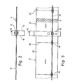
- the housing 12 forms a slot 13 which is eccentric here and is open at one edge. This gives the housing 12 an essentially U-shaped shape with legs 14 and 15 and a web 16 connecting them to one side on one side.
- the web 10 runs transversely for the longitudinal extension of the housing 12 through the slot 13, preferably in the horizontal plane.
- the monitoring elements namely optical or photoelectric sensors and display elements and the electronic and electrotechnical devices, are accommodated in the housing 12, which is formed with the slot 13 open on one side.
- the main carrier of these organs is a U-shaped or with a slot 13 formed circuit board 17. At the edge thereof, namely following the contours, a circumferential transverse wall 18 is formed. This also limits the slot 13 on both sides of the same.
- top walls 19 are expediently attached, which are part of the closed housing 12.
- the web 10 is scanned for any material defects by a first monitoring system, which consists of a transmitter 20 on one side and a receiver 21 on the other side of the slot 13 and thus the web 10.
- a test medium is emitted from the transmitter 20, preferably pulsating infrared light, which is received by the receiver 21 after passing through the web 10. Changes in the radiation or light intensity lead to a corresponding evaluation by evaluation electronics arranged downstream of the receiver 21 and possibly to the generation of an error signal.
- the infrared light is guided in the area of the (upper and lower) transverse wall 18 through a respective plan window 22 and 23 inside the same.
- An amplifier 24 is connected downstream of the receiver 21.
- a material strip is monitored independently of the web 10, namely a tear strip 25 which is attached (off-center) to the web 10.
- a tear strip 25 is common in the outer wrapping of packaging, especially in the outer foil wrapping of cigarette packs.
- the web 10 is provided with imaginary cross dividing lines 26, which are defined by blanks 27 to be separated from the web 10, each for a pack.
- the tear strip 26 extends over the full length of the blanks 27 and thus over the web 10.
- Pre-punched tabs 28 are marked at the ends for gripping the tear strip 25 when the packages are opened.
- the presence and the exact relative position of the tear strip 25 is monitored in the exemplary embodiment shown by an independent system which consists of a common transmitter 29 and two receivers 30 and 31 arranged at a distance from one another. The latter are ever because amplifier 32 downstream.
- the receivers 30 and 31 are arranged at a distance from one another (for example approx. 1 mm) which is somewhat smaller than the width of the tear strip 25. As a result, when the tear strip 25 is arranged in the normal position, both receivers 30, 31 are through it or covers the light beam. In the event of a deviation from the normal position, one or the other receiver 30, 31 is immediately exposed to infrared light, as a result of which an error signal is triggered and a correction movement with regard to the feeding of the tear strip 25 is initiated.
- the two monitoring systems 20, 21 on the one hand and 29, 30, 31 on the other hand can be assigned optical display elements 33 and 34, which here protrude from the housing 12 in the region of an end wall 35 thereof. Any errors are made visible (in addition) by the display elements 33, 34.
- the monitoring system with transmitter 29, receiver 30 and 31 fulfills a double function in the present case.
- the tear strip 25 is provided with a (color) identifier 36, in the embodiment of FIG. 4 in the area of the grip tab 28. In the present device, this is used as an additional monitoring aid, specifically for the exact relative position of the Web 10 to be cut blank 27 with respect to the package to be wrapped (not shown).
- the (color) identifier 36 is scanned by the transmitter 29 or the receiver 30, 31. The result is evaluated in such a way that, in the event of a determined difference in relation to the relative position, the conveying movement of the web 10 and thus the relative position of the blanks 27 are changed.
- the sensitivity can be set differently depending on the monitoring target.
- the connected actuating devices of the packaging machine can be set up and adjusted separately with regard to the speed, the size and the direction of the actuating values.
- the transmitters generate the infrared light in cycles (2 - 5 kHz) in order to largely switch off external light influences.
- the relative position of the organs can be selected so that the receivers 30, 31 are each half covered by the tear strip 25, that is to say deliver about half their possible output.
- the output values are set in the case of a central tear strip 25 so that they are approximately the same and the output signals do not yet report an error (threshold value setting depending on the permitted tolerance deviation in the lateral direction)
- the signals can be evaluated in various ways. If one of the amplifiers 32 or both emits an error signal, this can be passed on to the output as an error via an AND link.
- each amplifier 32 can emit a different signal, e.g. B. plus voltage on the one hand and minus voltage on the other. Both signals are given to a sum amplifier, the output of which is zero when the tear strip 25 is running properly.
- the permissible deviation of the tear strip 25 from the zero position can be set by means of hysteresis, which can be adjusted with a potentiometer, according to plus and minus values at the output. At the same time, these plus and minus values can be used to readjust the position of the tear strip using a correction actuator.
- the signals are derived here in order to discard the incorrect packs or stop the packaging machine.
Landscapes
- Engineering & Computer Science (AREA)
- Mechanical Engineering (AREA)
- Controlling Rewinding, Feeding, Winding, Or Abnormalities Of Webs (AREA)
- Making Paper Articles (AREA)
- Wrapping Of Specific Fragile Articles (AREA)
Abstract
Bei der Überwachung einer Bahn (10), insbesondere aus Verpackungsmaterial (Folie), werden zur Material - und Lageüberwachung (photoelektrische) Sensoren eingesetzt. Diese sind in bzw. an einem Gehäuse (12) untergebracht, welches als selbständige Einheit zu handhaben ist. Mehrere Überwachungssysteme zur Abtastung unterschiedlicher Merkmale der Bahn (10) bzw. eines Aufreißstreifens (25) sind in dem Gehäuse zu beiden Seiten eines einseitig offenen Schlitzes (13) angebracht.When monitoring a web (10), in particular from packaging material (foil), (photoelectric) sensors are used for material and position monitoring. These are housed in or on a housing (12) which can be handled as an independent unit. Several monitoring systems for scanning different features of the web (10) or a tear strip (25) are provided in the housing on both sides of a slot (13) which is open on one side.
Description
Die Erfindung betrifft eine Einrichtung zur Überwachung und Steuerung von Bahnen aus Verpackungsmaterial od. dgl. in bezug auf Material- und Stellungsfehler, insbesondere an Verpackungsmaschinen, mit Sensoren, vorzugsweise photoelektrischen Sendern und Empfängern, zum Abtasten der laufenden Bahn.The invention relates to a device for monitoring and controlling webs of packaging material or the like in relation to material and position errors, in particular on packaging machines, with sensors, preferably photoelectric transmitters and receivers, for scanning the running web.
Im Zusammenhang mit Verpackungsmaschinen ist die Überwachung von Material-Bahnen, insbesondere von Bahnen des Verpackungsmaterials, erforderlich. Zum einen geht es darum, Materialfehler zu identifizieren, beispielsweise Löcher, Risse, aber auch Bahnverbindungen durch Klebestreifen etc. Die Feststellung derartiger Fehler führt zu der Aussonderung einer oder mehrerer aus dem Verpackungsmaterial mit diesen Fehlern hergestellter Packungen, insbesondere Zigaretten-Packungen. Darüber hinaus ist aber auch der Lauf der Materialbahn, also deren Relativstellung, zu überwachen. Bei Abweichungen von den Soll-Positionen wird die Bahn durch geeignete Stellorgane in die korrekte Bewegungsrichtung verstellt.In connection with packaging machines, the monitoring of material webs, in particular webs of the packaging material, is necessary. On the one hand, it is about identifying material defects, for example holes, tears, but also rail connections using adhesive strips, etc. The determination of the This type of error leads to the rejection of one or more packs, in particular cigarette packs, made from the packaging material with these defects. In addition, the run of the material web, i.e. its relative position, must also be monitored. In the event of deviations from the target positions, the web is adjusted in the correct direction of movement by suitable actuators.
Eine Überwachungs- und Steuerungseinrichtung dieser Art ist in der EP-A-25 563 beschrieben. Einem Bobinen-Träger ist bei diesem bekannten Vorschlag ein photoelektrisches Abtastgerät zugeordnet, welches aus zwei im Abstand voneinander angeordneten Sensorstäben besteht. Zwischen diesen läuft die Bahn des Verpackungsmaterials hindurch, derart, daß eine Reihe von mit geringem Abstand voneinander angeordneten Sensoren jeweils zu beiden Seiten der Bahn sich erstreckt. Darüber hinaus sind an jedem Sensorstab zwei seitliche Sensoren (Sender und Empfänger) angeordnet, die die Seitenkanten der Bahn abtasten und einen etwaigen Schieflauf erkennen. Diese letztgenannten Sensoren bzw. etwaige Fehlersignale werden bei der bekannten Vorrichtung zur Betätigung eines Stellmotors verwendet, der die Bobine bzw. die Bobinenhalterung in korrigierendem Sinne verstellt.A monitoring and control device of this type is described in EP-A-25 563. In this known proposal, a bobbin support is assigned a photoelectric scanning device which consists of two sensor rods arranged at a distance from one another. The web of packaging material runs between them in such a way that a row of sensors arranged at a short distance from one another extends on either side of the web. In addition, two lateral sensors (transmitter and receiver) are arranged on each sensor rod, which scan the side edges of the web and detect any skew. These latter sensors or any error signals are used in the known device for actuating a servomotor which adjusts the bobbin or the bobbin holder in a corrective sense.
Die bekannte Einrichtung ist zwar zur Überwachung von Material- und Stellungsfehlern einer Materialbahn geeignet, jedoch im Aufbau und in der Handhabung verhältnismäßig aufwendig.Although the known device is suitable for monitoring material and position errors of a material web, it is relatively complex in construction and handling.
Der Erfindung liegt die Aufgabe zugrunde, eine im Aufbau einfache und kostengünstige, in der Funktion gleichwohl zuverlässige Einrichtung zur Überwachung von Material- und Stellungsfehlern in bzw. an Bahnen vorzuschlagen.The invention is based on the object of proposing a device which is simple and inexpensive in construction but nevertheless reliable in function for monitoring material and position errors in or on webs.
Zur Lösung dieser Aufgabe ist die erfindungsgemäße Einrichtung gekennzeichnet durch wenigstens zwei voneinander unabhängige Sensoren bzw. Gruppen von Sensoren zum Abtasten mehrerer Material- und Herstellungsmerkmale der Bahn.To achieve this object, the device according to the invention is characterized by at least two mutually independent Pending sensors or groups of sensors for scanning several material and manufacturing characteristics of the web.
Bei dem bevorzugten Ausführungsbeispiel der Erfindung sind zwei voneinander unabhängig betätigbare Gruppen von Sensoren vorgesehen. Eine erste Gruppe von lediglich zwei Sensoren, nämlich Sender und Empfänger, dient der Überwachung der Materialbeschaffenheit der Bahn. Der Sender ist dabei vorzugsweise als Lichtgeber (Infrarotlichtgeber) ausgebildεtund der Empfänger als Photodiode. Die Bahn wird zwischen Sender und Empfänger hindurchgeleitet, wobei Änderungen der Intensität des empfangenen Lichts durch den Empfänger registriert werden, z. B. Materialverdickungen oder -verdünnungen, Rissbildungen, Klebestreifen zum Verbinden von Enden aneinanderschließender Bahnen etc. Das vom Empfänger erzeugte Fehlersignal wird in der Weise verwendet, daß eine oder mehrere Packungen aus dem Bereich der fehlerhaften Bahn ausgesondert werden.In the preferred embodiment of the invention, two groups of sensors which can be actuated independently of one another are provided. A first group of only two sensors, namely transmitter and receiver, is used to monitor the material properties of the web. The transmitter is preferably designed as a light transmitter (infrared light transmitter) and the receiver as a photodiode. The web is passed between the transmitter and the receiver, changes in the intensity of the received light being registered by the receiver, e.g. B. material thickening or thinning, cracking, adhesive strips for connecting ends of contiguous webs etc. The error signal generated by the receiver is used in such a way that one or more packages from the area of the defective web are separated.
Eine Gruppe von weiteren Sensoren, nämlich einem Sender und zwei im Abstand voneinander angeordneten Empfängern, dient erfindungsgemäß der Überwachung eines auf die Bahn aufgebrachten Materialstreifens (Folien-Aufreißstreifen). Die Empfänger sind dabei in einem Abstand voneinander angeordnet, der geringer ist als die Breite des Folien-Aufreißstreifens, so daß beide Empfänger von diesem überdeckt sind. Bei einer Abweichung des Streifens von der Normallage wird dem einen oder anderen Sensor mehr Licht zugeführt, woraus ein Fehlersignal abgeleitet wird.A group of further sensors, namely a transmitter and two receivers arranged at a distance from one another, is used according to the invention to monitor a strip of material (film tear strip) applied to the web. The receivers are arranged at a distance from one another which is less than the width of the film tear strip, so that both receivers are covered by it. If the strip deviates from the normal position, one or the other sensor is supplied with more light, from which an error signal is derived.
Erfindungsgemäß hat diese Gruppe von Sensoren eine weitere Funktion, nämlich Überwachung der Relativlage der Verpakkungszuschnitte, die zusammen mit dem Materialstreifen von der Bahn abgetrennt werden. Zu diesem Zweck ist jeder Folien-Aufreißstreifen mit einer Markierung (farbige Kennmarke) versehen, die hinsichtlich der Relativlage von den Sensoren abgetastet wird. Eine Veränderung der Lage bedeutet auch eine nicht erwünschte Veränderung der Relativstellung des Zuschnitts.According to the invention, this group of sensors has a further function, namely monitoring the relative position of the packaging blanks, which are separated from the web together with the material strip. For this purpose, each film tear strip is provided with a marking (colored identification mark), which the Sen sensors is scanned. A change in the position also means an undesired change in the relative position of the blank.
Diese und ggf. weitere Sensoren sind nach einem weiteren Vorschlag der Erfindung in bzw. an einem gemeinsamen, einheitlichen Halter angeordnet, der U-förmig ausgebildet ist. An (horizontal) gerichteten Schenkeln sind die sich gegenüberliegenden Sensoren (Sender und Empfänger) angeordnet, wobei die Bahn im Bereich eines einseitig offenen Schlitzes zwischen den Sensoren hindürchgefördert wird. Diese sind auf einer gemeinsamen, U-förmigen Platine als Träger angebracht.According to a further proposal of the invention, these and possibly further sensors are arranged in or on a common, uniform holder which is U-shaped. The opposing sensors (transmitter and receiver) are arranged on (horizontally) directed legs, the web being conveyed through in the area of a slot open on one side between the sensors. These are mounted on a common, U-shaped board as a carrier.
Eine so ausgebildete Überwachungs-Einrichtung ist einfach zu handhaben, nämlich montierbar und erforderlichenfalls austauschbar. Die komplette Einrichtung ist als handels-und handhabungsfähige Einheit ausgebildet.A monitoring device designed in this way is easy to handle, namely mountable and, if necessary, interchangeable. The entire facility is designed as a unit that can be traded and handled.
Weitere Merkmale der Erfindung beziehen sich auf die konstruktive Ausbildung der Überwachungs-Einrichtung sowie auf deren Organe.Further features of the invention relate to the design of the monitoring device and its organs.
Ausführungsbeispiele der Erfindung werden nachfolgend anhand der Zeichnungen näher erläutert. Es zeigen:
- Fig. 1 eine Einheit zur Überwachung von Bahnen in Seitenansicht mit schematisch dargestellten Überwachungsorganen,
- Fig. 2 die Einheit gemäß Fig. 1 in Stirnansicht mit Bahn in verkleinertem Maßstab,
- Fig. 3 einen Grundriß zu Fig. 2,
- Fig. 4 eine Darstellung entsprechend Fig. 3 eines anderen Ausführungsbeispiels.
- 1 is a unit for monitoring webs in side view with schematically illustrated monitoring members,
- 2 shows the unit according to FIG. 1 in an end view with the track on a reduced scale,
- 3 is a plan view of FIG. 2,
- Fig. 4 is an illustration corresponding to Fig. 3 of another embodiment.
Das in den Zeichnungen dargestellte Ausführungsbeispiel einer Überwachungs- und Steuer-Einheit ist besonders geeignet in Verbindung mit Verpackungsmaschinen, vorzugsweise Zigarettenpackmaschinen. Eine fortlaufend der Verpackungsmaschine bzw. einem Verpackungsaggregat (z. B. Folienapparat) zulaufende Bahn 10, beispielsweise aus einer Kunststoff-Folie, ist in bezug auf Relativstellung, Fehler etc. abzutasten. Zu den Fehlern gehören Unregelmäßigkeiten in der Materialbeschaffenheit der Bahn 10 (Löcher, Risse, unerwünschte Verdickungen), aber auch querlaufende Klebestreifen 11 zum Verbinden der Enden aufeinanderfolgender Bahnen 10.The embodiment of a monitoring and control unit shown in the drawings is particularly suitable in connection with packaging machines, preferably cigarette packing machines. A
Die überwachungs-Einrichtung besteht aus bzw. ist in einem separaten Gehäuse 12 komplett untergebracht. Diese im vorliegenden Fall etwa rechteckige bzw. quaderförmige Einheit kann komplett in bzw. an der Verpackungsmaschine installiert und erforderlichenfalls ausgewechselt werden.The monitoring device consists of or is completely housed in a
Das Gehäuse 12 bildet einen hier außermittig liegenden, an einem Rand offenen Schlitz 13. Durch diesen erhält das Gehäuse 12 eine im wesentlichen U-förmige Gestalt mit Schenkeln 14 und 15 und einem diese an einer Seite miteinander verbindenden Steg 16. Die Bahn 10 läuft quer zur Längserstreckung des Gehäuses 12 durch den Schlitz 13 hindurch,vorzugsweise in horizontaler Ebene. In dem U-förmigen bzw. mit dem einseitig offenen Schlitz 13 ausgebildeten Gehäuse 12 sind die Überwachungsorgane, nämlich optische bzw. photoelektrische Sensoren sowie Anzeigeorgane und die elektronischen sowie elektrotechnischen Einrichtungen untergebracht. Hauptträger dieser Organe ist eine U-förmig bzw. mit einem Schlitz 13 ausgebildete Platine 17. Am Rand derselben, nämlich den Konturen folgend, ist eine ringsherumlaufende Querwand 18 gebildet. Diese begrenzt auch den Schlitz 13 zu beiden Seiten desselben. Außen sind zweckmäßigerweise Deckwandungen 19 angebracht, die Teil des geschlossenen Gehäuses 12 sind.The
Bei den hier gezeigten, bevorzugten Ausführungsbeispielen wird die Bahn 10 hinsichtlich etwaiger Materialfehler durch ein erstes überwachungssystem abgetastet, welches aus einem Sender 20 auf der einen und einem Empfänger 21 auf der anderen Seite des Schlitzes 13 und damit der Bahn 10 besteht. Von dem Sender 20 wird ein Prüfmedium ausgesendet, vorzugsweise pulsierendes Infrarotlicht, welches nach Durchtritt durch die Bahn 10 von dem Empfänger 21 aufgenommen wird. Veränderungen der Strahlungs- bzw. Lichtintensität führen zu einer entsprechenden Auswertung durch eine dem Empfänger 21 nachgeordnete Auswertungselektronik und ggf. zur Erzeugung eines Fehlersignals. Das Infrarotlicht wird im Bereich der (oberen und unteren) Querwand 18 durch jeweils ein Planfenster 22 und 23 innerhalb derselben hindurchgeleitet. Dem Empfänger 21 ist ein Verstärker 24 nachgeschaltet.In the preferred exemplary embodiments shown here, the
Bei dem vorliegenden Ausführungsbeispiel wird unabhängig von der Bahn 10 ein Materialstreifen überwacht, nämlich ein Aufreißstreifen 25, der (außermittig) auf der Bahn 10 angebracht ist. Ein derartiger Aufreißstreifen 25 ist bei Außenumhüllungen von Verpackungen üblich, insbesondere bei der äußeren Folienumhüllung von Zigaretten-Packungen. Die Bahn 10 ist zur Verdeutlichung bei den Darstellungen in Fig. 3 und 4 mit gedachten Quertrennlinien 26 versehen, die durch später von der Bahn 10 abzutrennende Zuschnitte 27, je für eine Packung, definiert sind. Der Aufreißstreifen 26 erstreckt sich über die volle Länge der Zuschnitte 27 und damit über die Bahn 10. An den Enden sind jeweils vorgestanzte Grifflaschen 28 zum Erfassen des Aufreißstreifens 25 beim öffnen der Packungen markiert.In the present exemplary embodiment, a material strip is monitored independently of the
Das Vorhandensein sowie die exakte Relativlage des Aufreißstreifens 25 wird bei dem gezeigten Ausführungsbeispiel durch ein unabhängiges System überwacht, welches aus einem gemeinsamen Sender 29 und zwei im Abstand voneinander angeordneten Empfängern 30 und 31 besteht. Letzteren sind jeweils Verstärker 32 nachgeordnet.The presence and the exact relative position of the
Die Empfänger 30 und 31 sind in einem Abstand voneinander angeordnet (z. B. ca. 1 mm), der etwas kleiner ist als die Breite des Aufreißstreifens 25. Dadurch sind bei Anordnung des Aufreißstreifens 25 in der Normalstellung beide Empfänger 30, 31 durch diesen bzw. das Lichtstrahlenbündel überdeckt. Bei einer Abweichung von der Normalstellung wird der eine oder andere Empfänger 30, 31 unmittelbar mit Infrarotlicht beaufschlagt, wodurch ein Fehlersignal ausgelöst und eine Korrekturbewegung hinsichtlich der Zuführung des Aufreißstreifens 25 eingeleitet wird.The
Den beiden Überwachungssystemen 20, 21 einerseits sowie 29, 30, 31 andererseits können optische Anzeigeorgane 33 und 34 zugeordnet sein, die hier im Bereich einer Stirnwand 35 des Gehäuses 12 aus diesem herausragen. Durch die Anzeigeorgane 33, 34 wird (zusätzlich) ein etwaiger Fehler sichtbar gemacht.The two
Das überwachungssystem mit Sender 29, Empfänger 30, und 31 erfüllt im vorliegenden Falle eine Doppelfunktion. Der Aufreißstreifen 25 ist zu diesem Zweck mit einem (Farb-)Kennzeichen 36 versehen, bei dem Ausführungsbeispiel der Fig.4 im Bereich der Grifflasche 28. Dieses wird bei der vorliegenden Einrichtung als zusätzliches Oberwachungshilfsmittel herangezogen, und zwar für die exakte Relativstellung des von der Bahn 10 abzutrennenden Zuschnitts 27 in bezug auf die einzuhüllende Packung (nicht gezeigt). Zu diesem Zweck wird das (Farb-)Kennzeichen 36 durch den Sender 29 bzw. die Empfänger 30, 31 abgetastet. Das Ergebnis wird dahingehend ausgewertet, daß im Falle einer festgestellten Differenz in bezug auf die Relativlage die Förderbewegung der Bahn 10 und damit die Relativstellung der Zuschnitte 27 verändert wird.The monitoring system with
Durch die Trennung der Überwachungssysteme voneinander ist eine unterschiedliche Einstellung der Empfindlichkeit derselben je nach dem überwachungsziel möglich. Des weiteren können die angeschlossenen Stelleinrichtungen der Verpakkungsmaschine hinsichtlich der Schnelligkeit, der Größe und Richtung der Stellwerte getrennt eingerichtet und justiert werden.By separating the monitoring systems from one another, the sensitivity can be set differently depending on the monitoring target. Furthermore, the connected actuating devices of the packaging machine can be set up and adjusted separately with regard to the speed, the size and the direction of the actuating values.
Das Infrarotlicht wird taktweise von den Sendern erzeugt (2 - 5 kHz), um Fremdlichteinflüsse weitgehend auszuschalten. Bei der Abtastung des Aufreißstreifens 25 kann die Relativstellung der Organe so gewählt werden, daß die Empfänger 30, 31 je zur Hälfte durch den Aufreißstreifen 25 überdeckt sind, also etwa ihre halbe mögliche Leistung liefern. Durch die jedem Empfänger 30, 31 nachgeschalteten, getrennten Verstärker 32 werden bei mittig verlaufendem Aufreißstreifen 25 die Ausgangswerte so eingestellt, daß sie annähernd gleich sind und die Ausgangssignale noch keinen Fehler melden.(Schwellenwert-Einstellung je nach zugelasssener Toleranzabweichung in seitlicher Richtung)The transmitters generate the infrared light in cycles (2 - 5 kHz) in order to largely switch off external light influences. When scanning the
Die Auswertung der Signale kann bei dieser Anordnung in verschiedener Weise erfolgen. Wenn einer der Verstärker 32 oder beide ein Fehlersignal abgeben, kann dieses über eine UND-Verknüpfung an den Ausgang als Fehler weitergegeben werden. Alternativ kann jeder Verstärker 32 ein unterschiedliches Signal abgeben, z. B. Plus-Spannung einerseits und Minus-Spannung andererseits. Beide Signale werden auf einen Summenverstärker gegeben, dessen Ausgang bei ordnungsgemäß laufendem Aufreißstreifen 25 Null ist. Durch mit Potentiometer einstellbare Hysteresen nach Plus- und Minuswerten am Ausgang kann die zulässige Abweichung des Aufreißstreifens 25 aus der Null-Lage eingestellt werden. Zugleich können diese Plus- und Minuswerte dazu dienen, über ein Korrekturstellglied die Lage des Aufreißstreifens wieder zu justieren. Des weiteren werden hier die Signale abgeleitet, um die Fehlpackungen auszusondern bzw. die Verpackungsmaschine anzuhalten.With this arrangement, the signals can be evaluated in various ways. If one of the
Claims (10)
Applications Claiming Priority (2)
| Application Number | Priority Date | Filing Date | Title |
|---|---|---|---|
| DE19833341539 DE3341539A1 (en) | 1983-11-17 | 1983-11-17 | DEVICE FOR MONITORING AND CONTROLLING RAILWAYS IN PACKAGING MACHINES |
| DE3341539 | 1983-11-17 |
Publications (3)
| Publication Number | Publication Date |
|---|---|
| EP0142129A2 true EP0142129A2 (en) | 1985-05-22 |
| EP0142129A3 EP0142129A3 (en) | 1985-07-03 |
| EP0142129B1 EP0142129B1 (en) | 1988-09-28 |
Family
ID=6214536
Family Applications (1)
| Application Number | Title | Priority Date | Filing Date |
|---|---|---|---|
| EP84113469A Expired EP0142129B1 (en) | 1983-11-17 | 1984-11-08 | Device for monitoring and controlling webs in packaging machines |
Country Status (6)
| Country | Link |
|---|---|
| US (1) | US4682038A (en) |
| EP (1) | EP0142129B1 (en) |
| JP (1) | JPS60123329A (en) |
| BR (1) | BR8405859A (en) |
| CA (1) | CA1253230A (en) |
| DE (2) | DE3341539A1 (en) |
Cited By (9)
| Publication number | Priority date | Publication date | Assignee | Title |
|---|---|---|---|---|
| EP0392085A1 (en) * | 1989-04-12 | 1990-10-17 | Landis & Gyr Betriebs AG | Device for measuring the track-deviation of a moving foil web |
| EP0586349A1 (en) * | 1992-06-17 | 1994-03-09 | G.D Societa' Per Azioni | A device for sensing the thickness of strip material, in particular in devices for changing rolls of metallized strip material automatically |
| WO1995013235A1 (en) * | 1993-11-11 | 1995-05-18 | Packline Limited | Packaging |
| EP0857652A1 (en) * | 1997-02-07 | 1998-08-12 | Focke & Co. (GmbH & Co.) | Method and device for the optoelectronic checking of packaging material |
| EP0965523A1 (en) * | 1998-06-19 | 1999-12-22 | Focke & Co. (GmbH & Co.) | Method and machine for manufacturing packages,particularly cigarette packages |
| US6230289B1 (en) | 1997-11-27 | 2001-05-08 | 3Com Technologies | Testing data packets |
| US6295616B1 (en) | 1997-11-27 | 2001-09-25 | 3 Com Technologies | Analysis of data streams |
| US6550025B1 (en) | 1997-11-27 | 2003-04-15 | 3Com Technologies | Last-in first-out data stacks and processing data using such data stacks |
| CN102502013A (en) * | 2011-11-11 | 2012-06-20 | 苏州晶雷光电照明科技有限公司 | LED strip winding device |
Families Citing this family (30)
| Publication number | Priority date | Publication date | Assignee | Title |
|---|---|---|---|---|
| FR2592487B1 (en) * | 1985-12-31 | 1988-03-11 | Centre Tech Ind Papier | DEVICE FOR DETECTING A TEAR PRIME ON A SHEET DURING ITS MANUFACTURE. |
| IT1189918B (en) * | 1986-01-27 | 1988-02-10 | Gd Spa | CONTROL DEVICE FOR CORRECT CONFORMATION OF PACKAGE ELEMENTS |
| DD268592A3 (en) * | 1986-12-30 | 1989-06-07 | Nagema Veb K | Device for monitoring packaging materials in packaging machines |
| DE3805248A1 (en) * | 1988-02-19 | 1989-08-31 | Dietrich Luederitz | Electronic apparatus for observing films |
| IT1233296B (en) * | 1989-01-10 | 1992-03-26 | Ima Spa | DEVICE FOR THE TEMPORARY INTERRUPTION OF THE FLOW OF ITEMS INTENDED TO BE PLACED INSIDE CORRESPONDING CELLS MADE ON A TAPE, IN A MACHINE FILLING MACHINE TAPES |
| JP2841204B2 (en) * | 1989-01-31 | 1998-12-24 | 東芝メカトロニクス株式会社 | Packaging method and equipment |
| US5187374A (en) * | 1991-03-21 | 1993-02-16 | Ncr Corporation | Optical paper sensing method and apparatus having light source and detector moveable in pivotal relation |
| US5457539A (en) * | 1993-06-18 | 1995-10-10 | Abb Industrial Systems, Inc. | On-line compensation for deflection in instruments using focused beams |
| DE19636365A1 (en) | 1996-09-06 | 1998-04-09 | Focke & Co | Hinged box and method of making the same |
| DE19725223A1 (en) * | 1997-06-14 | 1998-12-17 | Rovema Gmbh | Shell material carrier |
| US6075882A (en) * | 1997-06-18 | 2000-06-13 | Philip Morris Incorporated | System and method for optically inspecting cigarettes by detecting the lengths of cigarette sections |
| US5966218A (en) * | 1997-07-11 | 1999-10-12 | Philip Morris Incorporated | Bobbin optical inspection system |
| US6020969A (en) * | 1997-07-11 | 2000-02-01 | Philip Morris Incorporated | Cigarette making machine including band inspection |
| US6198537B1 (en) | 1997-07-11 | 2001-03-06 | Philip Morris Incorporated | Optical inspection system for the manufacture of banded cigarette paper |
| DE19817824A1 (en) | 1998-04-21 | 1999-10-28 | Focke & Co | Device for testing units from several individual objects, layers of material or the like |
| DE10021838A1 (en) * | 2000-05-05 | 2001-11-08 | Focke & Co | Device for manufacturing products and method for controlling such a device |
| EP1310154B1 (en) * | 2001-11-09 | 2007-12-19 | Welger Maschinenfabrik GmbH | Device for wrapping bodies, in particular bales of harvested material |
| EP1310153A1 (en) * | 2001-11-09 | 2003-05-14 | Lely Enterprises AG | Method for wrapping objects, particularly agricultural round bales |
| DE20120977U1 (en) | 2001-12-27 | 2003-04-30 | Bat Cigarettenfab Gmbh | Cutting control for an inner wrapper for a cigarette group |
| DE10246437A1 (en) * | 2002-10-04 | 2004-04-15 | Focke Gmbh & Co. Kg | Packaging film checking device for checking for the correct position of the tearing-off strip in packaging film comprises ultrasonic transmitter and receiver focussed on the area of the tearing-off strip |
| TWM330197U (en) * | 2007-05-08 | 2008-04-11 | Tsc Auto Id Technology Co Ltd | Sheet sensor for tab printer |
| EP2186624B1 (en) * | 2008-11-18 | 2015-08-26 | Tetra Laval Holdings & Finance S.A. | Apparatus and method for detecting the position of application of a sealing strip onto a web of packaging material for food products |
| DE102012025158A1 (en) * | 2012-12-21 | 2014-06-26 | Focke & Co. (Gmbh & Co. Kg) | Method and device for the automatic testing of flat sheet material |
| ITVR20130218A1 (en) * | 2013-09-20 | 2015-03-21 | Bema Srl | DEVICE AND PROCEDURE OF CONTROL OF THE QUALITY OF FILM EXTENSIBLE FOR PACKAGING |
| EP2923957A1 (en) * | 2014-03-26 | 2015-09-30 | UHLMANN PAC-SYSTEME GmbH & Co. KG | Device for adapting the control of a system for processing foil webs |
| CA3076449C (en) | 2017-09-22 | 2023-08-08 | Lantech.Com, Llc | Packaging material quality compensation |
| GB2593623B (en) * | 2018-11-27 | 2022-10-26 | Scatterbrain Pty Ltd | A first-aid kit container dispensing system |
| AU2020240019B2 (en) * | 2019-03-20 | 2023-03-30 | Lantech.Com, Llc | Packaging material evaluation and apparatus therefor for sensing packaging material flaws |
| CA3147091A1 (en) | 2019-09-19 | 2021-03-25 | Michael P. Mitchell | Ultrasonic packaging material flaw detection with time-limited response detection |
| US11518557B2 (en) | 2019-09-19 | 2022-12-06 | Lantech.Com, Llc | Packaging material grading and/or factory profiles |
Citations (4)
| Publication number | Priority date | Publication date | Assignee | Title |
|---|---|---|---|---|
| GB1507938A (en) * | 1975-07-17 | 1978-04-19 | Hurleton Altair | Register control system for a moving web |
| EP0043723A2 (en) * | 1980-07-07 | 1982-01-13 | Automated Packaging Systems, Inc. | Continuous web registration |
| US4386273A (en) * | 1980-05-01 | 1983-05-31 | The B. F. Goodrich Company | Positioner and slitter for laminar material |
| EP0108329A1 (en) * | 1982-11-05 | 1984-05-16 | Maschinenfabrik Alfred Schmermund GmbH & Co. | Device for controlling the presence of a fabric web |
Family Cites Families (15)
| Publication number | Priority date | Publication date | Assignee | Title |
|---|---|---|---|---|
| US2486334A (en) * | 1948-09-25 | 1949-10-25 | Westinghouse Electric Corp | Photoelectric scanner for register regulation |
| DE1041976B (en) * | 1954-08-13 | 1958-10-30 | Siemens Ag | Arrangement of registration marks on the print web for photoelectric side register control in multi-color rotary printing machines |
| DE1038569B (en) * | 1955-11-04 | 1958-09-11 | Iacellophaneia Invest Company | Device for compensating the transverse displacements of the edge of a film running off a roll, especially for printing machines |
| US3232547A (en) * | 1962-08-03 | 1966-02-01 | Hurletron Inc | Edge monitor device |
| JPS4929970U (en) * | 1972-06-16 | 1974-03-14 | ||
| JPS535016U (en) * | 1976-06-28 | 1978-01-18 | ||
| DE2831038C2 (en) * | 1978-07-14 | 1982-07-01 | Siemens AG, 1000 Berlin und 8000 München | Radiation diagnostic device for the generation of slice images |
| US4247204A (en) * | 1979-02-26 | 1981-01-27 | Intec Corporation | Method and apparatus for a web edge tracking flaw detection system |
| DE3034901A1 (en) * | 1979-09-17 | 1981-04-30 | Intec Corp., Trumbull, Conn. | Defect detector system automatic scanning beam positioner - has beam sensor next edge of moving web detecting laser beam position w.r.t. its scanning path |
| DE2937661A1 (en) * | 1979-09-18 | 1981-04-02 | Focke & Co, 2810 Verden | BOBINE HOLDER, ESPECIALLY FOR PACKAGING MACHINES |
| US4284356A (en) * | 1979-09-26 | 1981-08-18 | Ppg Industries, Inc. | Method of and apparatus for comparing surface reflectivity |
| DE3024698A1 (en) * | 1980-06-30 | 1982-01-28 | Rainer 7602 Oberkirch Hess | Contactless edge detector appts. - measures surface roughness using laser beam |
| DE3129808C2 (en) * | 1981-07-29 | 1983-06-16 | Feldmühle AG, 4000 Düsseldorf | Method for testing transparent material webs |
| DE3142316A1 (en) * | 1981-10-24 | 1983-05-05 | Heidelberger Druckmaschinen Ag, 6900 Heidelberg | DEVICE FOR CONTROLLING THE LATERAL POSITION OF A PRINTED MATERIAL RAIL IN ROLLING PRINTING MACHINES |
| JPH10163A (en) * | 1996-06-15 | 1998-01-06 | Chubu Corp:Kk | Method for using heat roaster |
-
1983
- 1983-11-17 DE DE19833341539 patent/DE3341539A1/en active Granted
-
1984
- 1984-11-02 CA CA000467002A patent/CA1253230A/en not_active Expired
- 1984-11-08 DE DE8484113469T patent/DE3474281D1/en not_active Expired
- 1984-11-08 EP EP84113469A patent/EP0142129B1/en not_active Expired
- 1984-11-15 US US06/671,843 patent/US4682038A/en not_active Expired - Lifetime
- 1984-11-15 JP JP59239614A patent/JPS60123329A/en active Granted
- 1984-11-16 BR BR8405859A patent/BR8405859A/en not_active IP Right Cessation
Patent Citations (4)
| Publication number | Priority date | Publication date | Assignee | Title |
|---|---|---|---|---|
| GB1507938A (en) * | 1975-07-17 | 1978-04-19 | Hurleton Altair | Register control system for a moving web |
| US4386273A (en) * | 1980-05-01 | 1983-05-31 | The B. F. Goodrich Company | Positioner and slitter for laminar material |
| EP0043723A2 (en) * | 1980-07-07 | 1982-01-13 | Automated Packaging Systems, Inc. | Continuous web registration |
| EP0108329A1 (en) * | 1982-11-05 | 1984-05-16 | Maschinenfabrik Alfred Schmermund GmbH & Co. | Device for controlling the presence of a fabric web |
Cited By (12)
| Publication number | Priority date | Publication date | Assignee | Title |
|---|---|---|---|---|
| EP0392085A1 (en) * | 1989-04-12 | 1990-10-17 | Landis & Gyr Betriebs AG | Device for measuring the track-deviation of a moving foil web |
| EP0586349A1 (en) * | 1992-06-17 | 1994-03-09 | G.D Societa' Per Azioni | A device for sensing the thickness of strip material, in particular in devices for changing rolls of metallized strip material automatically |
| US5521498A (en) * | 1992-06-17 | 1996-05-28 | G.D S.P.A. | Device for sensing the thickness of strip material in particular in devices for changing rolls of metallized strip material automatically |
| WO1995013235A1 (en) * | 1993-11-11 | 1995-05-18 | Packline Limited | Packaging |
| EP0857652A1 (en) * | 1997-02-07 | 1998-08-12 | Focke & Co. (GmbH & Co.) | Method and device for the optoelectronic checking of packaging material |
| US6038836A (en) * | 1997-02-07 | 2000-03-21 | Focke & Co. (Gmbh & Co.) | Process and apparatus for the optoelectronic monitoring of packaging material |
| US6230289B1 (en) | 1997-11-27 | 2001-05-08 | 3Com Technologies | Testing data packets |
| US6295616B1 (en) | 1997-11-27 | 2001-09-25 | 3 Com Technologies | Analysis of data streams |
| US6550025B1 (en) | 1997-11-27 | 2003-04-15 | 3Com Technologies | Last-in first-out data stacks and processing data using such data stacks |
| EP0965523A1 (en) * | 1998-06-19 | 1999-12-22 | Focke & Co. (GmbH & Co.) | Method and machine for manufacturing packages,particularly cigarette packages |
| US6308492B1 (en) | 1998-06-19 | 2001-10-30 | Focke & Co. (Gmbh & Co.) | Process and apparatus for producing packs |
| CN102502013A (en) * | 2011-11-11 | 2012-06-20 | 苏州晶雷光电照明科技有限公司 | LED strip winding device |
Also Published As
| Publication number | Publication date |
|---|---|
| BR8405859A (en) | 1985-09-17 |
| DE3341539C2 (en) | 1991-03-28 |
| CA1253230A (en) | 1989-04-25 |
| EP0142129A3 (en) | 1985-07-03 |
| JPH0317706B2 (en) | 1991-03-08 |
| JPS60123329A (en) | 1985-07-02 |
| DE3474281D1 (en) | 1988-11-03 |
| US4682038A (en) | 1987-07-21 |
| EP0142129B1 (en) | 1988-09-28 |
| DE3341539A1 (en) | 1985-05-30 |
Similar Documents
| Publication | Publication Date | Title |
|---|---|---|
| EP0142129A2 (en) | Device for monitoring and controlling webs in packaging machines | |
| DE3933196C2 (en) | Method and device for monitoring the belt run of a conveyor belt or a belt scale | |
| EP0309818B1 (en) | Device for separating material webs into (two) partial webs | |
| EP2958744B1 (en) | System and method for processing a paper web or corrugated cardboard web | |
| EP0157087A1 (en) | Device for checking batches of cigarettes | |
| DE4304322A1 (en) | Cutting of garment labels from roll - utilises electronic counters and sensors to ensure correct cutting position and to reject faulty labels | |
| DE2713844B2 (en) | Device for recognizing the value of coins or the like. Objects | |
| DE19909518A1 (en) | Position detection method of stacked flat material, especially paper stack at input of printing machine | |
| EP0086270B1 (en) | Control device for feeding webs | |
| EP2935023B1 (en) | Method and apparatus for producing outer wrappers | |
| DE10246437A1 (en) | Packaging film checking device for checking for the correct position of the tearing-off strip in packaging film comprises ultrasonic transmitter and receiver focussed on the area of the tearing-off strip | |
| DE3240254A1 (en) | Device for checking that a container has been completely filled with packages of cigarettes | |
| EP0381112B1 (en) | Method and apparatus for working webs in register, especially when producing safety yarns | |
| EP1021293B1 (en) | Method and device for checking the width of a material web | |
| DE3710068A1 (en) | Device for measuring the accuracy of movement and positioning of a machine part | |
| DE19632696C1 (en) | Method and device for measuring the overlap width of an overlap joint of two workpieces lying flat on one another | |
| CH648253A5 (en) | METHOD FOR REGISTERING AND DISCARDING THE INFULLY FILLED PACKS IN PACKING MACHINES. | |
| DE2802466C3 (en) | Method for measuring the distances between markings on a material web, in particular for measuring the distances between the transport edge perforations on a continuous paper web, and device for carrying out this method | |
| DE2420544C2 (en) | Device for monitoring the advance of a magnetizable strip of material | |
| DE3240825C2 (en) | Device for checking the presence of a web of material | |
| DE4103166A1 (en) | Real=time quality control for workpiece manufacturing process - uses sensor mechanisms to monitor each stage of process simultaneously to enable maintenance of tolerances | |
| DE10257143B4 (en) | Cut control for an inner wrapper for a cigarette group | |
| EP0534080B1 (en) | Continually controlled multi-part business form and method and apparatus for making the same | |
| DE19618504C2 (en) | Method and device for dynamic weighing of piece goods | |
| EP1070935A2 (en) | Device to control the width of sealing joints |
Legal Events
| Date | Code | Title | Description |
|---|---|---|---|
| PUAI | Public reference made under article 153(3) epc to a published international application that has entered the european phase |
Free format text: ORIGINAL CODE: 0009012 |
|
| PUAL | Search report despatched |
Free format text: ORIGINAL CODE: 0009013 |
|
| AK | Designated contracting states |
Designated state(s): DE FR GB IT NL SE |
|
| AK | Designated contracting states |
Designated state(s): DE FR GB IT NL SE |
|
| 17P | Request for examination filed |
Effective date: 19850807 |
|
| RAP1 | Party data changed (applicant data changed or rights of an application transferred) |
Owner name: FOCKE & CO. (GMBH & CO.) |
|
| 17Q | First examination report despatched |
Effective date: 19860611 |
|
| R17C | First examination report despatched (corrected) |
Effective date: 19870130 |
|
| ITF | It: translation for a ep patent filed |
Owner name: STUDIO MASSARI S.R.L. |
|
| GRAA | (expected) grant |
Free format text: ORIGINAL CODE: 0009210 |
|
| AK | Designated contracting states |
Kind code of ref document: B1 Designated state(s): DE FR GB IT NL SE |
|
| GBT | Gb: translation of ep patent filed (gb section 77(6)(a)/1977) | ||
| REF | Corresponds to: |
Ref document number: 3474281 Country of ref document: DE Date of ref document: 19881103 |
|
| ET | Fr: translation filed | ||
| PLBE | No opposition filed within time limit |
Free format text: ORIGINAL CODE: 0009261 |
|
| STAA | Information on the status of an ep patent application or granted ep patent |
Free format text: STATUS: NO OPPOSITION FILED WITHIN TIME LIMIT |
|
| 26N | No opposition filed | ||
| ITTA | It: last paid annual fee | ||
| PGFP | Annual fee paid to national office [announced via postgrant information from national office to epo] |
Ref country code: SE Payment date: 19931117 Year of fee payment: 10 |
|
| PG25 | Lapsed in a contracting state [announced via postgrant information from national office to epo] |
Ref country code: SE Effective date: 19941109 |
|
| EAL | Se: european patent in force in sweden |
Ref document number: 84113469.5 |
|
| EUG | Se: european patent has lapsed |
Ref document number: 84113469.5 |
|
| PGFP | Annual fee paid to national office [announced via postgrant information from national office to epo] |
Ref country code: FR Payment date: 19981110 Year of fee payment: 15 |
|
| PGFP | Annual fee paid to national office [announced via postgrant information from national office to epo] |
Ref country code: DE Payment date: 19991120 Year of fee payment: 16 |
|
| PGFP | Annual fee paid to national office [announced via postgrant information from national office to epo] |
Ref country code: NL Payment date: 19991228 Year of fee payment: 16 |
|
| PG25 | Lapsed in a contracting state [announced via postgrant information from national office to epo] |
Ref country code: FR Free format text: LAPSE BECAUSE OF NON-PAYMENT OF DUE FEES Effective date: 20000731 |
|
| REG | Reference to a national code |
Ref country code: FR Ref legal event code: ST |
|
| PG25 | Lapsed in a contracting state [announced via postgrant information from national office to epo] |
Ref country code: NL Free format text: LAPSE BECAUSE OF NON-PAYMENT OF DUE FEES Effective date: 20010601 |
|
| NLV4 | Nl: lapsed or anulled due to non-payment of the annual fee |
Effective date: 20010601 |
|
| PG25 | Lapsed in a contracting state [announced via postgrant information from national office to epo] |
Ref country code: DE Free format text: LAPSE BECAUSE OF NON-PAYMENT OF DUE FEES Effective date: 20010801 |
|
| PGFP | Annual fee paid to national office [announced via postgrant information from national office to epo] |
Ref country code: GB Payment date: 20011107 Year of fee payment: 18 |
|
| REG | Reference to a national code |
Ref country code: GB Ref legal event code: IF02 |
|
| PG25 | Lapsed in a contracting state [announced via postgrant information from national office to epo] |
Ref country code: GB Free format text: LAPSE BECAUSE OF NON-PAYMENT OF DUE FEES Effective date: 20021108 |
|
| GBPC | Gb: european patent ceased through non-payment of renewal fee |