EP0136735A1 - Arrangement for checking the counting function of counters - Google Patents
Arrangement for checking the counting function of counters Download PDFInfo
- Publication number
- EP0136735A1 EP0136735A1 EP84201110A EP84201110A EP0136735A1 EP 0136735 A1 EP0136735 A1 EP 0136735A1 EP 84201110 A EP84201110 A EP 84201110A EP 84201110 A EP84201110 A EP 84201110A EP 0136735 A1 EP0136735 A1 EP 0136735A1
- Authority
- EP
- European Patent Office
- Prior art keywords
- counters
- counter
- counting
- parity
- positions
- Prior art date
- Legal status (The legal status is an assumption and is not a legal conclusion. Google has not performed a legal analysis and makes no representation as to the accuracy of the status listed.)
- Granted
Links
Images
Classifications
-
- H—ELECTRICITY
- H03—ELECTRONIC CIRCUITRY
- H03K—PULSE TECHNIQUE
- H03K21/00—Details of pulse counters or frequency dividers
- H03K21/40—Monitoring; Error detection; Preventing or correcting improper counter operation
Definitions
- the invention relates to an arrangement for checking the counting function of a number n(n >, 2) of counters which are operated isochronously.
- a parity generator for generating the parity of the instantaneous counting position is connected to each counter, that each of the (n-1) parity generators connected to the counters having the highest counter position is connected to a shift register for shifting the parity of the relevant parity generator by a number of positions corresponding to the difference between the counting positions of the relevant counter and the counter having the lowest counting position, that an output of each of the (n-1) shift registers and an output of the parity generator connected to the counter having the lowest counting position are connected to a logic circuit, that a first signal is supplied from the output of the logic circuit if the same parity is presented to all inputs, whilst a second signal is supplied when this is not the case.
- the invention is based on the recognition of the fact that when the arrangement includes more than one counter it is possible to check the counters already present in the arrangement against each other and consequently it is not necessary to duplicate each counter.
- a parity generator PC is connected to an output of each counter and generates the parity of the counting position of the counter to which it is connected.
- the counters are operated isochronously which means that repeatedly and simultaneously counting pulses are applied to all counters but that the counting positions of the counters may mutually be unequal. The mutual difference in counting positions is however constant. Since the counting positions of the counters CNT i are unequal the parities generated therefrom will generally also be unequal.
- the shift register SR i delays (or shifts) the parity bits applied to it over the number of positions corresponding to the difference between the counting position of the relevant counter (CNT i ) and the counting position of the counter having the lowest counting position (CNT n ).
- the instantaneous counting position of counter CNT 1 is, for example, 137, the counting position of counter CNT n-1 is 87 and that of counter CNT n is 18, then shift register SR 1 must have 119 shift positions and shift register SR n-1 must have 69 shift positions.
- the output signals of the shift registers SR 1 to SR n-1 , inclusive are now in synchronism with the output signal of counter CNT .
- These signals are applied to an co-incidence circuit LC for example an exclusive-OR circuit in the case where only two counters are present.
- a first signal is supplied from an output OUT of the co-incidence circuit LC when all input signals are equal and a second signal when the input signals are not all equal.
Abstract
Description
- The invention relates to an arrangement for checking the counting function of a number n(n >, 2) of counters which are operated isochronously.
- In order to check a binary counter for proper operation it is known to duplicate the counter and to apply the pulses to be counted to both counters. After each counting pulse either the counting positions or the parities generated across the counter positions are compared with each other. When it is found that counter positions are not identical or have unequal parities, an alarm signal is generated. This alarm signal is an indication that a defect has occurred in one of the two counters or in one of the two parity generators.
- If a system requires a plurality of counters which are not operated synchronously but isochronously, all these counters should be duplicated if the above- described way of checking the proper operation is opted for. This implies a significant extension of the system.
- It is an object of the invention to provide an arrangement with which the counting functions of a plurality of isochronous counters are checked in a simple way. To accomplish this the arrangement according to the invention set forth in the opening paragraph, is characterized in that a parity generator for generating the parity of the instantaneous counting position is connected to each counter, that each of the (n-1) parity generators connected to the counters having the highest counter position is connected to a shift register for shifting the parity of the relevant parity generator by a number of positions corresponding to the difference between the counting positions of the relevant counter and the counter having the lowest counting position, that an output of each of the (n-1) shift registers and an output of the parity generator connected to the counter having the lowest counting position are connected to a logic circuit, that a first signal is supplied from the output of the logic circuit if the same parity is presented to all inputs, whilst a second signal is supplied when this is not the case.
- The invention is based on the recognition of the fact that when the arrangement includes more than one counter it is possible to check the counters already present in the arrangement against each other and consequently it is not necessary to duplicate each counter.
- Further particulars of the arrangement according to the invention will be described by way of example with reference to the embodiment shown in the sole Figure of the accompanying drawing.
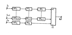
- The Figure shows a number of binary counters CNTi (i = 1, 2, ..., n-1, n ≥ 2) each having an input I for receicing counting pulses. A parity generator PC. is connected to an output of each counter and generates the parity of the counting position of the counter to which it is connected. The counters are operated isochronously which means that repeatedly and simultaneously counting pulses are applied to all counters but that the counting positions of the counters may mutually be unequal. The mutual difference in counting positions is however constant. Since the counting positions of the counters CNTi are unequal the parities generated therefrom will generally also be unequal.
- The parity bits of the (n-1) counters having the highest counting positions are applied to a shift register SRi (i = 1, 2, ..., n-1) which to that end is connected to an output of the relevant parity generator. (In the figure it is assumed that the counters CNT1 to CNTn-1, inclusive have the highest counting positions). The shift register SRi delays (or shifts) the parity bits applied to it over the number of positions corresponding to the difference between the counting position of the relevant counter (CNTi) and the counting position of the counter having the lowest counting position (CNTn). If the instantaneous counting position of counter CNT1 is, for example, 137, the counting position of counter CNTn-1 is 87 and that of counter CNTn is 18, then shift register SR1 must have 119 shift positions and shift register SRn-1 must have 69 shift positions. The output signals of the shift registers SR1 to SRn-1, inclusive are now in synchronism with the output signal of counter CNT . These signals are applied to an co-incidence circuit LC for example an exclusive-OR circuit in the case where only two counters are present. A first signal is supplied from an output OUT of the co-incidence circuit LC when all input signals are equal and a second signal when the input signals are not all equal. In the said first case this means that all the parity bits applied,are equal (all "1" or all "O") and from this it may be concluded, at least be assumed with a high degree of probability, that the counting positions to which the parity bits relate are isochronous. In the case in which a second signal is supplied from output OUT not all the parity bits were equal to each other and the isochronism is obviously disturbed.
- An arrangement for checking the counting function of isochronous counters is more specifically used in cases in which two counters (n=2) are used, such as for example checking individual write and read counters for memory addressing purposes.
Claims (1)
- An arrangement for checking the counting function of a number n(n ≥ 2) of counters which are operated isochronously, characterized in that a parity generator for generating the parity of the instantaneous counting position is connected to each counter, that each of the (n-1) parity generators connected to the counters having the highest counting position is connected to a shift register for shifting the parity of the televant parity generator by a number of positions corresponding to the difference between the counting positions of the relevant counter and the counter having the lowest counting position, that an output of each of the (n-1) shift registers and an output of the parity generator connected to the counter having the lowest counting position are connected to a logic circuit, that a first signal is supplied from the output of the logic circuit if the same parity is presented to all inputs, whilst a second signal is supplied when this is not the case.
Applications Claiming Priority (2)
| Application Number | Priority Date | Filing Date | Title |
|---|---|---|---|
| NL8302722A NL8302722A (en) | 1983-08-01 | 1983-08-01 | DEVICE FOR MONITORING THE COUNTING FUNCTION OF COUNTERS. |
| NL8302722 | 1983-08-01 |
Publications (2)
| Publication Number | Publication Date |
|---|---|
| EP0136735A1 true EP0136735A1 (en) | 1985-04-10 |
| EP0136735B1 EP0136735B1 (en) | 1988-01-07 |
Family
ID=19842219
Family Applications (1)
| Application Number | Title | Priority Date | Filing Date |
|---|---|---|---|
| EP84201110A Expired EP0136735B1 (en) | 1983-08-01 | 1984-07-30 | Arrangement for checking the counting function of counters |
Country Status (5)
| Country | Link |
|---|---|
| US (1) | US4606057A (en) |
| EP (1) | EP0136735B1 (en) |
| JP (1) | JPS6052113A (en) |
| DE (1) | DE3468601D1 (en) |
| NL (1) | NL8302722A (en) |
Families Citing this family (3)
| Publication number | Priority date | Publication date | Assignee | Title |
|---|---|---|---|---|
| US5046076A (en) * | 1988-09-19 | 1991-09-03 | Dynetics Engineering Corporation | Credit card counter with phase error detecting and precount comparing verification system |
| US5440604A (en) * | 1994-04-26 | 1995-08-08 | Unisys Corporation | Counter malfunction detection using prior, current and predicted parity |
| US11374576B1 (en) * | 2020-12-30 | 2022-06-28 | Texas Instruments Incorporated | Self-diagnostic counter |
Citations (4)
| Publication number | Priority date | Publication date | Assignee | Title |
|---|---|---|---|---|
| US3567916A (en) * | 1969-01-22 | 1971-03-02 | Us Army | Apparatus for parity checking a binary register |
| US3898444A (en) * | 1973-12-28 | 1975-08-05 | Ibm | Binary counter with error detection and transient error correction |
| GB2062307A (en) * | 1979-11-09 | 1981-05-20 | Gen Signal Corp | A Vital Timer |
| US4278898A (en) * | 1979-08-13 | 1981-07-14 | The United States Of America As Represented By The Secretary Of The Navy | Frequency comparator for electronic clocks |
Family Cites Families (7)
| Publication number | Priority date | Publication date | Assignee | Title |
|---|---|---|---|---|
| US3113204A (en) * | 1958-03-31 | 1963-12-03 | Bell Telephone Labor Inc | Parity checked shift register counting circuits |
| US3117219A (en) * | 1960-12-21 | 1964-01-07 | Honeywell Regulator Co | Electrical circuit operation monitoring apparatus |
| JPS4832923B1 (en) * | 1967-05-23 | 1973-10-09 | ||
| US3668431A (en) * | 1970-10-23 | 1972-06-06 | Burroughs Corp | Functions comparing circuit |
| US3911261A (en) * | 1974-09-09 | 1975-10-07 | Ibm | Parity prediction and checking network |
| JPS5283046A (en) * | 1975-12-30 | 1977-07-11 | Fujitsu Ltd | Check system of error detection circuit |
| US4130818A (en) * | 1977-04-21 | 1978-12-19 | Communications Satellite Corporation | Analog threshold decoding |
-
1983
- 1983-08-01 NL NL8302722A patent/NL8302722A/en not_active Application Discontinuation
-
1984
- 1984-07-19 US US06/632,497 patent/US4606057A/en not_active Expired - Fee Related
- 1984-07-28 JP JP59156536A patent/JPS6052113A/en active Granted
- 1984-07-30 EP EP84201110A patent/EP0136735B1/en not_active Expired
- 1984-07-30 DE DE8484201110T patent/DE3468601D1/en not_active Expired
Patent Citations (4)
| Publication number | Priority date | Publication date | Assignee | Title |
|---|---|---|---|---|
| US3567916A (en) * | 1969-01-22 | 1971-03-02 | Us Army | Apparatus for parity checking a binary register |
| US3898444A (en) * | 1973-12-28 | 1975-08-05 | Ibm | Binary counter with error detection and transient error correction |
| US4278898A (en) * | 1979-08-13 | 1981-07-14 | The United States Of America As Represented By The Secretary Of The Navy | Frequency comparator for electronic clocks |
| GB2062307A (en) * | 1979-11-09 | 1981-05-20 | Gen Signal Corp | A Vital Timer |
Also Published As
| Publication number | Publication date |
|---|---|
| JPH04417B2 (en) | 1992-01-07 |
| DE3468601D1 (en) | 1988-02-11 |
| NL8302722A (en) | 1985-03-01 |
| US4606057A (en) | 1986-08-12 |
| EP0136735B1 (en) | 1988-01-07 |
| JPS6052113A (en) | 1985-03-25 |
Similar Documents
| Publication | Publication Date | Title |
|---|---|---|
| US4498174A (en) | Parallel cyclic redundancy checking circuit | |
| US3924181A (en) | Test circuitry employing a cyclic code generator | |
| US4454600A (en) | Parallel cyclic redundancy checking circuit | |
| US5297151A (en) | Adjustable weighted random test pattern generator for logic circuits | |
| US4059749A (en) | Digital monitor | |
| US4498178A (en) | Data error correction circuit | |
| US4606057A (en) | Arrangement for checking the counting function of counters | |
| US6765932B1 (en) | Method and apparatus for synchronizing a data stream | |
| US20030229836A1 (en) | Integrated circuit | |
| US4482819A (en) | Data processor system clock checking system | |
| US4982403A (en) | Electrical circuit testing device and circuit comprising the said device | |
| US3701096A (en) | Detection of errors in shift register sequences | |
| US4713813A (en) | Logic analyzer | |
| US6027243A (en) | Parity check circuit | |
| US4608691A (en) | Signature analyzer card | |
| US5694400A (en) | Checking data integrity in buffered data transmission | |
| US5682388A (en) | Data testing | |
| JPH0431211B2 (en) | ||
| US3336468A (en) | Hamming magnitude determinator using binary threshold logic elements | |
| US5067132A (en) | One out of n checking apparatus and method | |
| SU1705876A1 (en) | Device for checking read/write memory units | |
| SU1531174A1 (en) | Memory with correction of single errors | |
| SU696625A1 (en) | Device for receiving discrete information for systems with solving feedback | |
| SU1272358A1 (en) | Versions of storage with self-check | |
| SU1160414A1 (en) | Device for checking logic units |
Legal Events
| Date | Code | Title | Description |
|---|---|---|---|
| PUAI | Public reference made under article 153(3) epc to a published international application that has entered the european phase |
Free format text: ORIGINAL CODE: 0009012 |
|
| AK | Designated contracting states |
Designated state(s): DE FR GB NL SE |
|
| 16A | New documents despatched to applicant after publication of the search report | ||
| 17P | Request for examination filed |
Effective date: 19851007 |
|
| 17Q | First examination report despatched |
Effective date: 19860919 |
|
| GRAA | (expected) grant |
Free format text: ORIGINAL CODE: 0009210 |
|
| AK | Designated contracting states |
Kind code of ref document: B1 Designated state(s): DE FR GB NL SE |
|
| REF | Corresponds to: |
Ref document number: 3468601 Country of ref document: DE Date of ref document: 19880211 |
|
| ET | Fr: translation filed | ||
| PLBE | No opposition filed within time limit |
Free format text: ORIGINAL CODE: 0009261 |
|
| STAA | Information on the status of an ep patent application or granted ep patent |
Free format text: STATUS: NO OPPOSITION FILED WITHIN TIME LIMIT |
|
| 26N | No opposition filed | ||
| PGFP | Annual fee paid to national office [announced via postgrant information from national office to epo] |
Ref country code: FR Payment date: 19900720 Year of fee payment: 7 |
|
| PGFP | Annual fee paid to national office [announced via postgrant information from national office to epo] |
Ref country code: SE Payment date: 19900726 Year of fee payment: 7 |
|
| PGFP | Annual fee paid to national office [announced via postgrant information from national office to epo] |
Ref country code: NL Payment date: 19900731 Year of fee payment: 7 |
|
| PGFP | Annual fee paid to national office [announced via postgrant information from national office to epo] |
Ref country code: DE Payment date: 19900921 Year of fee payment: 7 |
|
| PGFP | Annual fee paid to national office [announced via postgrant information from national office to epo] |
Ref country code: GB Payment date: 19910701 Year of fee payment: 8 |
|
| PG25 | Lapsed in a contracting state [announced via postgrant information from national office to epo] |
Ref country code: SE Effective date: 19910731 |
|
| PG25 | Lapsed in a contracting state [announced via postgrant information from national office to epo] |
Ref country code: NL Effective date: 19920201 |
|
| NLV4 | Nl: lapsed or anulled due to non-payment of the annual fee | ||
| PG25 | Lapsed in a contracting state [announced via postgrant information from national office to epo] |
Ref country code: FR Effective date: 19920331 |
|
| PG25 | Lapsed in a contracting state [announced via postgrant information from national office to epo] |
Ref country code: DE Effective date: 19920401 |
|
| REG | Reference to a national code |
Ref country code: FR Ref legal event code: ST |
|
| PG25 | Lapsed in a contracting state [announced via postgrant information from national office to epo] |
Ref country code: GB Effective date: 19920730 |
|
| GBPC | Gb: european patent ceased through non-payment of renewal fee |
Effective date: 19920730 |
|
| EUG | Se: european patent has lapsed |
Ref document number: 84201110.8 Effective date: 19920210 |