EP0136718B1 - Dual level pattern recognition system - Google Patents
Dual level pattern recognition system Download PDFInfo
- Publication number
- EP0136718B1 EP0136718B1 EP84111901A EP84111901A EP0136718B1 EP 0136718 B1 EP0136718 B1 EP 0136718B1 EP 84111901 A EP84111901 A EP 84111901A EP 84111901 A EP84111901 A EP 84111901A EP 0136718 B1 EP0136718 B1 EP 0136718B1
- Authority
- EP
- European Patent Office
- Prior art keywords
- character
- coarse
- array
- fine
- ambiguous
- Prior art date
- Legal status (The legal status is an assumption and is not a legal conclusion. Google has not performed a legal analysis and makes no representation as to the accuracy of the status listed.)
- Expired - Lifetime
Links
Images


Classifications
-
- G—PHYSICS
- G06—COMPUTING; CALCULATING OR COUNTING
- G06V—IMAGE OR VIDEO RECOGNITION OR UNDERSTANDING
- G06V30/00—Character recognition; Recognising digital ink; Document-oriented image-based pattern recognition
- G06V30/10—Character recognition
- G06V30/24—Character recognition characterised by the processing or recognition method
- G06V30/248—Character recognition characterised by the processing or recognition method involving plural approaches, e.g. verification by template match; Resolving confusion among similar patterns, e.g. "O" versus "Q"
- G06V30/2504—Coarse or fine approaches, e.g. resolution of ambiguities or multiscale approaches
Definitions
- This invention relates to identifying patterns as corresponding to one of a set of reference characters.
- Yamamoto et al discloses a system in which an unknown pattern, e.g. a workpiece pattern, is converted into a signal derived from a coarse array representation of the unknown pattern, and classified into categories by comparing the signal to a set of pattern-classifying signals. The unknown pattern to be recognized is then identified by comparing a signal derived from a fine array representation of the unknown pattern to a set of reference signals derived from fine array representations of reference characters selected in the classification analysis.
- This prior art analysis is time-consuming.
- the invention features a pattern recognition system having both coarse and fine levels of analysis in which a coarse array representation of an unknown pattern is formed and used to identify the pattern to be recognized as either a reference character or as a member of an ambiguous set of reference characters which are represented by identical coarse array representations. At least portions of a fine array representation of a workpiece pattern which has been classified as a member of a set of reference characters are compared to corresponding portions of fine array representations of reference characters in the set identified by the classification. A workpiece pattern which is not identified as a reference character during a first coarse and fine array analyses is re-encoded into coarse and fine array representations and analyzed again.
- the pattern recognition system has a learning system through which reference characters may be introduced into the recognition system and through which a representation of an unknown pattern which is not identified may be incorporated into an existing set of reference characters of the recognition system.
- the coarse array representation of a reference character may, according to the invention, operate as an address to an entry in a first database.
- Each first database entry contains a multiplicity field giving the number of reference characters in the set represented by the coarse array representation.
- Each first database entry contains a second field giving a code for a reference character having an unambiguous coarse array value or an address to an entry in a second database for a pattern having an ambiguous coarse array value.
- Each second database entry contains an identifying code for its reference character and at least portions of the fine array representation of the reference character for use in resolving ambiguities between the reference character and the other reference characters represented by the same coarse array.
- Second database entries for each reference character represented by identical coarse arrays are grouped together sequentially within the second database.
- the pattern learning system may accept a workpiece pattern as a new reference character by comparing the coarse array representation of the workpiece pattern to the coarse array representations of an existing set of reference characters. For new reference characters for which no identical coarse array representation is found, an identifying character code is stored in a first database with the new coarse array representation of the reference character as its address. For a new reference character for which an identical coarse array representation is found, second database entries for a new set of reference characters represented by identical coarse arrays are generated, and a first database entry containing the number of reference characters in the new set and the address of the first of the second database entries for the set is established.
- the pattern learning system may use a measure of distinctiveness for isolating the most distinctive portions of fine array representations of reference characters represented by identical coarse arrays; the most distinctive portions are used by the pattern recognition system to resolve ambiguities between reference characters represented by identical coarse arrays.
- Advantages of the pattern recognition system of the present invention over prior art systems include shorter processing time for each character recognition analysis resulting from the fewer character comparisons necessary to unambiguously identify a workpiece character. Specifically, for reference characters having unambiguous coarse array representations, only coarse analysis need be performed. Further, since reference characters represented by identical coarse arrays are organized into sets of reference characters, called ambiguous sets, and fine analysis is confined to the members of the one ambiguous set which shares the same coarse array representation as the workpiece character, the number of members of the ambiguous set is the maximum number of characters examined during fine analysis.
- the number of picture elements which are analyzed to identify an unkown pattern to be recognized e.g. a workpiece character or to classify it into a set is limited to the number of picture elements in the coarse array.
- Fig. 1 shows a block diagram of an apparatus for operating the pattern recognition system of the present invention.
- Fig. 2 shows a block diagram of the D2 Character Recognizer shown in Fig. 1.
- Fig. 3 shows a block diagram of an apparatus for operating the pattern learning system of the present invention.
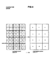
- Fig. 4 shows diagrammatically the coarse and fine arrays into which each character is organized.
- Fig. 5 shows a flow charted representation of the program which is used to compress a fine character array into a coarse character array.
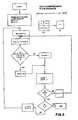
- Fig. 6 shows a flow charted representation of the pattern learning system for generating sets of reference characters represented by identical coarse arrays and entries in a first database for reference characters having unambiguous coarse array representations.
- Fig. 7 shows a flow charted representation of the pattern learning system for generating first database and second database entries for reference characters represented by identical coarse arrays.
- Fig. 8 shows a more detailed flow chart of second database entry generation, as shown in Fig. 7.
- Fig. 9 shows a more detailed flow chart of distinctive cell selection, as shown in Fig. 8.
- Fig. 10 shows diagrammatically one of the twelve learning matrices constructed during the pattern learning system for generating D2RAM entries.
- Fig. 11 shows diagrammatically the maximum discrimination matrix which is constructed from the twelve learning matrices.
- Fig. 12 shows an example of digitizing and compressing a typical character.
- Fig. 13 shows an example of generating second database entries for characters represented by identical coarse arrays.
- Fig. 14 shows the structure by which the entries of the first and second databases are organized.
- FIG. 1 a block diagram of an apparatus for operating the character recognition system 10 of the present invention.
- the system 10 has a digitizer 12 with which a pattern is quantized into a 6x8 array of binary elements (the fine array), a compressor 14 in which a 48 element fine array is compressed into a 3x4 array of binary elements (the coarse array), and a character name inputter 20 with multiplexer 22 for accepting the name of the character once a workpiece character is identified.
- Pattern recognizing system 10 has a first database D1RAM. Each entry thereof being addressed by a 12-bit value of a coarse array. Each entry in D1RAM has a multiplicity field of three bits which contains the number of characters in the reference set which ave the coarse array value of the entry address. Each entry in D1RAM has a second field with contents which depend on the value in the multiplicity field of the entry. When the entry in the multiplicity field of the entry in 1 (meaning there is only one reference character with a coarse array value equal to the entry address) the second field contains the identifying code of the single reference character. When the value in the multiplicity field is greater than 1 (meaning there are a plurality of reference characters with coarse array values equal to the entry address). The second field contains an address to D2RAM.
- D2RAM contains an entry for each reference character set which has a coarse array value equal to that of any other character. (That is all that do not have unshared coarse array values.) All characters with a common value of coarse array value are called an ambiguous set and the entries therefor are contiguous in D2RAM. The first address for the entries of an ambiguous set is that given for the set in D1RAM.
- Each D2 entry is organized into seven fields over two words of D2RAM memory.
- the first and third fields contain information identifying the two subsets of the 48 element fine array of that reference character which are most discriminating with respect to the other members of its ambiguous set; the second and fourth fields contain the values of the identified subsets.
- the fifth and sixth field in the second word of the D2 entry are reserved; the seventh field contains the identifying code for the reference character.
- the apparatus for use in coarse analysis has D1RAM, a first database address register D1AR arranged to be loaded with the coarse array representation of an workpiece character, a first database buffer register D1BR arranged to accept a 16 bit word from D1RAM, and a first database D1 character recognizer 16 arranged to be loaded with the first field of the D1 entry.
- the apparatus for use in fine analysis has D2RAM, a second database address register D2AR arranged to be loaded with the second field of a D1 entry, a second database buffer register D2BR arranged to accept a 16 bit word from D2RAM, and a second database character recognizer 36 arranged to be loaded with the fine array representation of a workpiece pattern and the first word of a D2 entry.
- D2 character recognizer 36 has 12 four bit cell registers 40 in which the 48 element fine array representation of the workpiece pattern is stored temporarily during both coarse and fine analysis, a 16 bit register 44 into which the first word of a D2RAM entry is loaded from D2BR, decoders 42, 52 arranged to select two of the cell registers 40 from address location information stored in sections I and III of register 44, a corresponding bit comparer 46 arranged to do an exclusive-NOR comparison on the contents of the two registers 40 selected by decoders 42, 52 and the element values stored in sections II and IV in register 44, and a disambiguation impossibility recognizer 90 arranged to be enabled by decoders 42, 52 to indicate that workpiece pattern can not be identified unambiguously but may be one of two or more members of an identified ambiguous set.
- a block diagram is shown of an apparatus for operating the character learning system 50 of the present invention.
- Learning system 50 shares, with recognition system 10, controls 30, digitizer 12, compressor 14, D1RAM, D1AR, D1BR, D2RAM, D2AR and D2BR.
- Learning system 50 has an input counter 54 arranged to be loaded with the number of reference characters to be encoded and inputted into pattern recognition system 10, a character name selector 56 for inputting an identifying binary character code CH(0-7) for each inputted reference character, and (normally offline) learning list storage 60 for storing the coarse and fine array representations and CH(0-7) for every reference character.
- List storage 60 has a set counter 62 arranged to be loaded with the number of reference characters in storage 60.
- Character learning system 50 has character learner 70 arranged to accept the first field of a D1BR entry into ambiguity counter 64, the second field into code register 76, and CM(0-7) and the contents of D2AR into D1 entry generator 58, in order to generate a D1 entry in D1 entry generator 58 based on the value of ambiguity counter 64. Character learner 70 also has D1 entry counter 74 arranged to be loaded with the number of entries in D1RAM.
- character learner 70 For generating D2 entries, character learner 70 is arranged to accept CH(0-7) and the contents of code register 76 into ambiguous set storage 66 in order to isolate sets of reference characters represented by identical coarse arrays. Character learner 70 has D2 entry generator 68 arranged to accept the fine array representations of every member of an ambiguous set as stored in ambiguous sets storage 66 in order to determine the most descriminating portions of each reference character with respect to the other members of its ambiguous set and, accordingly, generate entries for D2RAM.
- the character recognition system 10 uses digitizer 12 to encode workpiece character, into a 48 element fine array of binary numbers representative of the positional distribution of optical density within the pattern.
- the character is baseline and left-most justified with respect to a template with a 6x8 array of picture fields, where the descending portion of a character occupies the lower two rows of the array, and an ascending portion occupies the first two rows.
- a value 1 is assigned to an element of the coarse array if any part of a character appears in the corresponding field of the template and otherwise a 0 is assigned.
- the fine array which is temporarily stored in cell registers 40 within D2 character recognizer 48, with vlaues derived from one block of four picture fields in each register, is compressed into a 3x4 coarse array by operation of compressor 14, which converts the 48-bit output value DG (0-47) of digitizer 12 into the compressed 12-bit output value of the compressor 14.
- each element of CP(0-11) represents the same area as a block of four picture elements of DG(0-47).
- Recognition system 10 employs a data compression program 15 which essentially establishes a value of "1" to a compressed picture element, hereinafter called a cell, if any of the corresponding four picture elements in the fine array equals "1".
- a data compression program written in Algol (and flowcharted in Fig. 5) follows. In both the program and the flowchart, "a” is a picture element of the fine array, "C” is a cell of the coarse array, and "d” is a row counter for the coarse array.
- controls 30 load D1AR with CP(0-11), the coarse array representation of the workpiece pattern.
- CP(0-11) operates as an address to a D1RAM entry, which is then read into D1BR.
- Controls 30 cause D1 character recognizer 16 to be loaded with the first three bits of D1BR, hereinafter called N, which contain the multiplicity, of reference characters represented by the coarse array CP(0-11).
- D1 character recognizer 16 If the first three bits D1BR(0-2) equal zero, then no reference character in the current recognition system is represented by the coarse array of the workpiece pattern. D1 character recognizer 16 generates a signal X0, upon receipt of which controls 30 order a second encoding, decompression, and analysis of the workpiece character. If recognition system 10 is unable to identify the workpiece pattern after a second analysis and the signal XO is generated twice in a row, controls 30 cause character name inputter 30 to accept an "unidentified character" code. The operator of recognition system 10 may elect to incorporate the workpiece pattern into the set of reference characters by triggering the pattern learning system 50, described below.
- D1BR(0-2) the coarse array defined by CP(0-11) represents only one reference character.
- D1 character recognizer 16 generates a signal X1 which causes character name inputter 20 to be loaded with D1BR(8-15), the identifying binary character code for the reference character represented by the coarse array CP(0-11). Controls 30 then trigger digitizer 12 to digitize the next workpiece character for input into recognition system 10.
- D1BR(0-2) is greater than one
- the coarse array (CP(0-11) represents a distinct ambiguous set of reference characters.
- D1 character recognizer 16 generates the signal X2 which triggers a fine analysis to resolve the ambiguity.
- Controls 30 cause N, the number of the reference characters in the ambiguous set so identified, to be transferred from D1 character recognizer 16 to ambiguity down counter 48 within recognizer 36.
- Controls 30 also cause D2AR to be loaded with D1BR(3-15), the address the first D2RAM entry of the ambiguous set so identified. The first word of the D2RAM entry addressed by D2AR is read first into D2BR and then into register 44 of the D2 character recognizer 36.
- the first word of a D2RAM entry for a reference character contains the locations and element bit values of the most distinctive portions of the reference character with respect to the other members in its ambiguous set.
- the portions analyzed for distinctiveness by character learner 70 correspond to cells of a coarse array, one of which is shown in Fig. 4.
- each of the first and third fields in a D2 entry contains a binary number from 0 to 11, identifying which two of the twelve cells of a reference character are sufficiently distinctive to resolve ambiguities between the reference character and other reference characters in its ambiguous set.
- the second and fourth fields contain the element bit values of those distinctive cells.
- the first and third fields may also contain the number 15, indicating a reference character of an ambiguous set which can not be unambiguously identified.
- controls 30 cause the first and third field of a D1 entry to be loaded into sections I and III of register 44, and the second and fourth fields to be loaded into sections II and IV of register 44.
- Decoders 42, 52 attached to the outputs of sections I and III, decode the first and third fields of the D2 entry and, if the binary numbers are between 0 and 11, enable the reading of two of the twelve temporary registers 40; if decoders 42, 54 decode the number 15, they enable the disambiguation impossibility recognizer 90.
- cell registers 40 store the 48 element fine array representation of the workpiece pattern, one cell to each four bit register 44. Decoders 42, 52 enable the reading of the two cell registers 40 which correspond to the distinctive cells of the fine array.
- bit comparer 46 the element bit values of Section II and the cell register 40 enabled by decoded Section I and the element bit values of Section IV and the cell register 40 enabled by decoded Section III are compared, bit by bit, for equivalence by exclusive-NOR circuitry.
- Corresponding bit comparer 46 generates the signal Y2 which causes controls 30 to increment D2AR so that the second word of the D2RAM entry, which contains the identifying binary character code for the reference character, is read into D2BR.
- Y2 also enables character name inputter 20 and multiplexer 22 to accept the identifying character code D2BR(8-15) from D2BR, and triggers digitizer 12 to digitize the next workpiece character for identification.
- corresponding bit comparer 46 If corresponding bit comparer 46 does not find identical corresponding cells, it generates the signal Y1 which causes controls 30 to start a fine analysis of the next reference character in the ambiguous set. Controls 30 decrement the ambiguity down counter 48; if it does not equal zero, the ambiguous set contains more reference characters against which the workpiece pattern may be compared, so controls 30 increment D2BR twice so as to access the first word of the D2RAM entry of the next reference character in the ambiguous set. Fine analysis of reference characters continues until the workpiece pattern is identified or until all of the members of the ambiguous set have been analyzed.
- D2 character recognizer 38 When ambiguous down counter 18 is zero and the disambiguation recognizer 90 has been activated during analysis of the ambiguous set, D2 character recognizer 38 generates the signal Y0. Upon receipt of Y0, controls 30 cause D2AR to be incremented and the character code in D2 entry field seven to be inputted into character name inputter 20 along with an ambiguity indicator. In this manner, a similar if not unambiguously identified reference character is included in the system output for use in visual inspection by the operator.
- ambiguity down counter 48 When ambiguity down counter 48 equals zero, and the disambiguation impossible recognizer 90 has not been activated during analysis of the ambiguous set, controls 30 order a second encoding, compressing, and analysis of the workpiece character. If character recognition system 10 is unable to identify the workpiece pattern after the second try, controls 30 cause D2AR to be incremented and the character code character in D2 entry field seven to be loaded into character name inputter 20 along with an ambiguity indicator. The operator of recognition system 10 may choose to incorporate the workpiece character into the reference set by triggering 10 character learning system 50.
- Fig 6 which shows the procedure for generating D1 entries for reference characters having unambiguous coarse arrays
- the operator of character learning system 50 loads into input counter 54 the number of characters to be inputted.
- the number in counter 54 thus is either the number of characters to be incorporated into an existing set reference or the number of members of a new reference set.
- the operator of learning system 50 then places the first character leftmost and baseline justified onto the 6x8 element digitizing grid of digitizer 12. Control is transferred to compressor 14, which compresses the fine array DG(0-47) into the 12 element coarse array CP(0-11) with the same compression program described above and shown in Fig. 5.
- System 50 pauses until the operator inputs, through character name selector 56, the binary coded character name CH(0-7) of the new reference character.
- Controls 30 then cause the new reference character to be added to the reference set by loading the CH(0-7), CP(0-11) and DG(0-47) into offline learning list storage 60 and incrementing set counter 62. Controls 30 then decrements input counter 54. If input counter 54 has not reached zero, there are more characters to add to list storage 60, and control is again transferred to digitizer 12.
- controls 30 cause character learner 70 of learning system 50 to generate D1RAM and D2RAM entries for every reference character stored in learning list storage 60.
- Controls 30 generate signals to clear D1RAM, D2RAM, code register 76, and D1 entry counter 74.
- Controls 30 also load input counter 54 with the contents of set counter 62 so that the number of reference characters that are being entered into character recognition system 50 may be monitored through input counter 54.
- Controls 30 then cause the character code CH(0-7) for the first character in storage 60 to be read and loaded into D1 entry generator 58 within character learner 70.
- the coarse array CP(0-11) of the first character is loaded into D1AR, where it operates as an address to a D1RAM entry, which is read into D1BR.
- Controls 30 cause ambiguity counter 64 within character learner 70 to be loaded with the first three bits of D1BR, so that ambiguity counter 64 contains the number, called hereinafter "N", of reference characters represented by the coarse array CP(0-11). Controls also cause the remainder of D1BR, D1BR (3-15) to be loaded into code register 76 with character learner 70.
- character learner 50 When P does not equal zero (indicating that a D1 entry had been generated for an earlier-introduced reference character also represented by coarse array CP(0-11)), character learner 50 operates to either set up an ambiguous set for the reference characters represented by P and CH(0-7) or to add CH(0-7) to an already established ambiguous set of which the reference character represented by P is a part.
- N the number of reference characters represented by the coarse array CP(0-11), is examined.
- N is greater than 1, then an ambiguous set having P as a member has already been established in ambiguous set storage 66; controls 30 cause CM(0-7) to be added in storage 66 to that ambiguous set. If N equals 1, no such ambiguous set has been established; controls 30 cause an ambiguous set to be formed, with P as its first member and CH(0-7) as its second member. In both cases, ambiguity counter 64 is incremented the include the new reference character, and N is loaded into D1BR[0-2].
- the new D1 entry is written into D1RAM at the location addressed by CP(0-11).
- Input counter 54 is then decremented; if it is not equal to zero, list storage 60 contains more reference characters to be entered into D1RAM. Controls 30 cause the next character in from storage 60 to be read into D1AR and character learner 70. If input counter 54 is zero, the entire reference set has been read from storage 60; controls 30 trigger the portion of the learning system 50, shown in Fig. 8, which generates D2 entries and final D1 entries for ambiguous reference characters.
- controls 30 cause the value of 1 to be loaded into D1AR and D2AR, so that both the first and second database both address registers are set to reference their first available memory spaces.
- Controls 30 cause the D1RAM location so addressed to be read into D1BR.
- Ambiguity counter 64 is then loaded with D1BR[0-2], and its contents N are examined. If N equals 0, no reference character in storage 60 is represented by the coarse array in D1AR; neither D1 nor D2 entries are generated. Character learner 70 accesses the next D1 entry.
- D1 entry counter 74 which holds the number of D1 entries which have not been analyzed, equals 0, there are no more D1 entries from which D2 entries may be generated. The D2 entries for every ambiguous set have been generated, so character learning system 50 ends.
- D1 entry counter 74 If D1 entry counter 74 is non-zero, at least one D1 entry has not yet been analyzed; controls 30 cause D1AR to be incremented, and the next addressable D1 location is read into D1BR. If the first field of the D1 entry, i.e. N, is equal to one, the coarse array courrently in D1AR is representative of the single reference characters identified by D1BR[8-l5]; a D2 entry is not generated. Since the D1 entry is in final form, controls 30 cause the next addressable location in D1RAM to be analyzed.
- the coarse array CP(0-11) currently in D1AR represents more than one reference character.
- Character learner 70 preceeds to generate sequential D2 entries for each of the reference characters represented by CP(0-11) and a D1 entry addressing the first of those D2 entries.
- Character learner 70 loads code register 76 with D1BR(8-15) and loads D1BR(3-15) with D2AR, the address of the first available location in D2RAM. Controls 30 write D1BR into the D1RAM entry addressed by D1AR, and then generates the D2 entries for every member of the ambiguous set of which P is a member.
- each D2 entry for every reference character which is not represented by an unambiguous coarse array.
- Each D2 entry consists of seven fields over two D2RAM words, with the first four fields containing information as to the location and element values of the two most distinctive portions of the reference character in issue with respect the other meters of its ambiguous set.
- the second word of the D2 entry has a reserved fifth and sixth fields and a seventh field which contains the identifying binary character code for the reference character in issue.
- controls 30 cause character learner 70 to read ambiguous set storage 66 for a list of the binary codes CH(0-7) of all of the members of the ambiguous set of which P, as stored in code register 76, is a member. Controls 30 then cause character learner 70 to read, from offline learning list storage 60, the fine array representations DG[0-47] for every member of the isolated ambiguous set.
- Character learner 70 then starts the procedure by which most distinctive cells of each member of the ambiguous set are isolated. It examines each character individually and generates a measure of relative cell distinctiveness for every cell of that character with respect to every member of the ambiguous set. It organizes the cell distinctiveness measures into twelve matrices M0-M11, one matrix for each of the twelve cells in a character.
- a representative matrix M K , K 0,1,...11, is shown in Fig. 10.
- M K (i,j) is a measure of cell distinctiveness for cell K in character i with respect to character j.
- the measure of cell distinctiveness is the number of non-identical elements within corresponding 4-element cells of two characters.
- M K (i,j) is the summation of an exclusive-OR comparison of each of the four bits in corresponding cells K of two characters i, j.
- the value 0 indicates that the corresponding cells are identical in i and j and a value of 4 indicates that corresponding cells K are totally dissimilar, having the greatest amount of relative cell distinctiveness.
- the twelve learning matrices for D, C, and 0 are shown in Fig. 13.f.
- each element of the matrices M9-M11 for character cells below the descender line is zero.
- all of the elements of M1, M2, M3, M4, M7 and M8 are zero because corresponding cells 1, 2, 3, 4, 7, and 8 in D, C, and O are identical.
- character learner 70 isolates the maximum cell distinctiveness value maxM K (i) for every character in matrix M K as seen in Fig. 10, there are N maxims cell distinctiveness values for every cell K. As shown in Fig. 11, character learner 70 organizes all of the maximum cell distinctiveness values into a maximum distinctiveness matrix of size Nx12 for use with the 12 learning matrices in isolating, for each character in the ambiguous set, the two most distinctive cells, hereinafter called K1 and K2, which will be used by character recognition system 10 to resolve ambiguities between that character and the other members of its ambiguous set.
- K1 and K2 are not selected solely on the basis of their maximum cell distinctiveness values.
- the two cells of a pattern having the numerically greatest maximum cell distinctiveness values can not be used to resolve ambiguities within the set, because at those cell locations, the structure of the pattern is identical to the structure of another pattern in its ambiguous set.
- FIG. 13 An example of this is seen in Fig. 13, in which cell 0 and cell 6 of character C have the numerically greatest maximum cell distinctiveness values (i.e., 2) because of the structural differences between the characters C and 0, but can not be used to resolve differences between C and 0 because they are identical to cell 0 and cell 6 of character O.
- the numerically greatest maximum cell distinctiveness values i.e., 2
- K1 and K2 are selected as the most distinctive cells of a reference character P based on a large maximum distinctiveness value and the requirement that both of the cells K1 and K2 of character P can not be identical to the cells K1 and K2 of any other pattern in its ambiguous set.
- character learner 70 first generates the maximum distinctiveness matrix row for the character identified by P. Analyzing that row and the 12 learning matrices, character learner 70 selects K1 and K2, the address and contents of which are loaded into D2 entry generator 88.
- the first step in selecting K1 and K2 is to determine whether there are at least two values of maxM K (P) which are non-zero; if not, K1 and K2 selection for character P is impossible, and ambiguities between P and the other members of the ambiguous set cannot be resolved.
- Controls 30 cause D2 entry register 88 to be filled with all ones so that, when the D2 entry for P is accessed during use of pattern recognition system 10, values of fifteen in Sections I and III of D2 character register 44 cause disambiguation impossiblity recognizer 90 to be activated.
- character learner 70 selects, as an intial K1, the first cell in the maximum distinctiveness matrix row that has the largest value of maxM K (P).
- the cell selected as initial K1 is then excluded from further cell selection for two reasons: to avoid selecting one cell as both K1 and K2 to keep track of which cell combinations have been tested for K1, K2 ambiguity-resolving suitability.
- Character learner 70 causes the cells earlier discarded as K2 selections to be reincluded in the eligible cell set. To prevent retesting of cell combinations, earlier K1 cell selections continue to be excluded from the eligible cell set. Character learner 70 selects a new K1 and tests it with the eligible K2 cells for ambiguity-resolving suitability. It continues this cycle until a suitable K1 and K2 are selected or until it has tested every combination of cells having non-zero maxM K (P) values.
- character learner 70 causes D2 entry register 88 to be filled with all ones so that the first and second fields of the D2 entry indicate that disambiguation involving the character P is impossible.
- character learner 70 causes D2 entry register 88 to be filled with the address and picture element values of K1, K2.
- K1, K2 selection is illustrated in Fig. 13.
- Character learner generate the D row of the maximum distinctiveness matrix of Fig. 13.e, and selects cell 0 and cell 6, having distinctiveness values of 2, as initial K1 and K2 of matrices M0 and M6 shows that M0(D,C),M6(D,C) and M0 (D,O) and M6(D,O) are all non-zero, so that cells 0 and 6 are a suitable combination for use in resolving ambiguities between D and the other characters in the ambiguous set.
- Character learner 70 selects the combination of cells 0 to 5 to resolve ambiguities between O and the other member C and D of its ambiguous set.
- the D2 entries for D, C and O, generated by character learner 70, are shown in Fig. 13.f.
- controls 30 cause D2 entry register to be loaded into D2BR, and D2BR to be read into D2RAM at the location addressed by D2AR.
- D2AR is incremented to provide access to the next memory word in D2RAM, and character learner 70 causes P to be loaded into D2BR[8-15].
- character learner 70 causes P to be loaded into D2BR[8-15].
- D2BR is read into D2RAM, and ambiguity counter 64 is decremented so that N includes one less unanalyzed reference character in the ambiguous set.
- Character learner 70 continues to generate D2 entries for the rest of the members of the ambiguous set. As long as N is non-zero, character learner 70 increments D2AR to access the next memory location in D2RAM and loads code register 76 with P, the next character in the ambiguous set. When N becomes zero, character learner 70, which has generated D2 entries for all of the members of the ambiguous set defined by CP(0-11) in D1AR, accesses the next D1 entry in D1RAM in order to isolate the next ambiguous set.
- character learner 70 increments D2AR to access the next available unfilled memory word of D2RAM and decrements D1 entry counter 74 to include one fewer unanalyzed D1 entry; if D1 entry counter 74 is non-zero, character learner 70 accesses the next addressable location in D1RAM.
- D1 entry counter is zero, character learner 70 has generated D1 and if necessary, D2 entries for every reference character stored in the list storage 60. Controls 30 cause character learner 60 to exit pattern learning system 50.
- the first field of a D1 entry could be increased to accommodate reference sets having ambiguous sets with many members.
- the recognizing and learning systems and apparatus could be modified to accommodate longer identifying character codes for reference characters in a larger reference set.
- the apparatus and systems could also be modified to accommodate larger or smaller fine arrays.
- the apparatus and systems would be modified accordingly.
- the coarse array would also be modified in size.
- reference sets for example, in some type fonts, there are no characters which occupy both ascender and descender space in a character window. In other words, there are no characters which occupy cells 0-2 and cells 9-11 at the same time.
- a reference character may be represented by a 48 picture element fine array and a 9 cell coarse array . Digitizer 12 and compressor 14 would both still generate DG(0-47) and CP(0-11), but reference characters not occupying descender spaces would have coarse arrays corresponding to CP(0-8), while reference characters occupying descender space would have coarse arrays corresponding to CP(3-11).
- the pattern learning system would isolate ambiguous sets of characters represented by initial coarse array, but, in this embodiment, where the coarse array would have 9 elements, ambiguous sets could contain seemingly dissimilar characters which are easily disambiguated during fine analysis of the 48 element fine array representations DG(0-47).
- the fine array representations could also be modified to contain only 36 elements. Reference characters not occupying descender space would have fine arrays corresponding to DG(0-35), and reference characters occupying descender space would have fine arrays corresponding to DG(12-47).
Description
- This invention relates to identifying patterns as corresponding to one of a set of reference characters.
- A number of pattern recognition systems have been devised in which both coarse and fine analyses have been made of an unknown pattern. One patent, Yamamoto et al (US-A 3,829,831), discloses a system in which an unknown pattern, e.g. a workpiece pattern, is converted into a signal derived from a coarse array representation of the unknown pattern, and classified into categories by comparing the signal to a set of pattern-classifying signals. The unknown pattern to be recognized is then identified by comparing a signal derived from a fine array representation of the unknown pattern to a set of reference signals derived from fine array representations of reference characters selected in the classification analysis. This prior art analysis is time-consuming.
- It is an object of the invention to devise a dual level pattern recognition system achieving shorter recognition times as heretofore possible.
- A dual level pattern recognition system solving this problem and its further development are defined in the appendant claims.
- The invention features a pattern recognition system having both coarse and fine levels of analysis in which a coarse array representation of an unknown pattern is formed and used to identify the pattern to be recognized as either a reference character or as a member of an ambiguous set of reference characters which are represented by identical coarse array representations. At least portions of a fine array representation of a workpiece pattern which has been classified as a member of a set of reference characters are compared to corresponding portions of fine array representations of reference characters in the set identified by the classification. A workpiece pattern which is not identified as a reference character during a first coarse and fine array analyses is re-encoded into coarse and fine array representations and analyzed again. The pattern recognition system has a learning system through which reference characters may be introduced into the recognition system and through which a representation of an unknown pattern which is not identified may be incorporated into an existing set of reference characters of the recognition system.
- The coarse array representation of a reference character may, according to the invention, operate as an address to an entry in a first database. Each first database entry contains a multiplicity field giving the number of reference characters in the set represented by the coarse array representation. Each first database entry contains a second field giving a code for a reference character having an unambiguous coarse array value or an address to an entry in a second database for a pattern having an ambiguous coarse array value. There is a second database entry for every reference character which is not unambiguously defined by a coarse array representation. Each second database entry contains an identifying code for its reference character and at least portions of the fine array representation of the reference character for use in resolving ambiguities between the reference character and the other reference characters represented by the same coarse array. Second database entries for each reference character represented by identical coarse arrays are grouped together sequentially within the second database.
- Also according to the invention, the pattern learning system may accept a workpiece pattern as a new reference character by comparing the coarse array representation of the workpiece pattern to the coarse array representations of an existing set of reference characters. For new reference characters for which no identical coarse array representation is found, an identifying character code is stored in a first database with the new coarse array representation of the reference character as its address. For a new reference character for which an identical coarse array representation is found, second database entries for a new set of reference characters represented by identical coarse arrays are generated, and a first database entry containing the number of reference characters in the new set and the address of the first of the second database entries for the set is established.
- The pattern learning system may use a measure of distinctiveness for isolating the most distinctive portions of fine array representations of reference characters represented by identical coarse arrays; the most distinctive portions are used by the pattern recognition system to resolve ambiguities between reference characters represented by identical coarse arrays.
- Advantages of the pattern recognition system of the present invention over prior art systems include shorter processing time for each character recognition analysis resulting from the fewer character comparisons necessary to unambiguously identify a workpiece character. Specifically, for reference characters having unambiguous coarse array representations, only coarse analysis need be performed. Further, since reference characters represented by identical coarse arrays are organized into sets of reference characters, called ambiguous sets, and fine analysis is confined to the members of the one ambiguous set which shares the same coarse array representation as the workpiece character, the number of members of the ambiguous set is the maximum number of characters examined during fine analysis.
- On an even more fundamental level, since the coarse analysis is conducted using a coarse array scheme, the number of picture elements which are analyzed to identify an unkown pattern to be recognized, e.g. a workpiece character or to classify it into a set is limited to the number of picture elements in the coarse array.
- Further, in fine analysis, only the most distinctive portions of a fine array representation of a reference character are examined; therefore, the number of picture elements which identify a workpiece character not having a distinctive coarse array representation is limited to the number of picture elements in the most distinctive portions of the fine array representation of the reference character.
- Fig. 1 shows a block diagram of an apparatus for operating the pattern recognition system of the present invention.
- Fig. 2 shows a block diagram of the D2 Character Recognizer shown in Fig. 1.
- Fig. 3 shows a block diagram of an apparatus for operating the pattern learning system of the present invention.
- Fig. 4 shows diagrammatically the coarse and fine arrays into which each character is organized.
- Fig. 5 shows a flow charted representation of the program which is used to compress a fine character array into a coarse character array.
- Fig. 6 shows a flow charted representation of the pattern learning system for generating sets of reference characters represented by identical coarse arrays and entries in a first database for reference characters having unambiguous coarse array representations.
- Fig. 7 shows a flow charted representation of the pattern learning system for generating first database and second database entries for reference characters represented by identical coarse arrays.
- Fig. 8 shows a more detailed flow chart of second database entry generation, as shown in Fig. 7.
- Fig. 9 shows a more detailed flow chart of distinctive cell selection, as shown in Fig. 8.
- Fig. 10 shows diagrammatically one of the twelve learning matrices constructed during the pattern learning system for generating D2RAM entries.
- Fig. 11 shows diagrammatically the maximum discrimination matrix which is constructed from the twelve learning matrices.
- Fig. 12 shows an example of digitizing and compressing a typical character.
- Fig. 13 shows an example of generating second database entries for characters represented by identical coarse arrays.
- Fig. 14 shows the structure by which the entries of the first and second databases are organized.
- There is shown in Fig. 1 a block diagram of an apparatus for operating the
character recognition system 10 of the present invention. Thesystem 10 has adigitizer 12 with which a pattern is quantized into a 6x8 array of binary elements (the fine array), acompressor 14 in which a 48 element fine array is compressed into a 3x4 array of binary elements (the coarse array), and acharacter name inputter 20 withmultiplexer 22 for accepting the name of the character once a workpiece character is identified. -
Pattern recognizing system 10 has a first database D1RAM. Each entry thereof being addressed by a 12-bit value of a coarse array. Each entry in D1RAM has a multiplicity field of three bits which contains the number of characters in the reference set which ave the coarse array value of the entry address. Each entry in D1RAM has a second field with contents which depend on the value in the multiplicity field of the entry. When the entry in the multiplicity field of the entry in 1 (meaning there is only one reference character with a coarse array value equal to the entry address) the second field contains the identifying code of the single reference character. When the value in the multiplicity field is greater than 1 (meaning there are a plurality of reference characters with coarse array values equal to the entry address). The second field contains an address to D2RAM. - D2RAM contains an entry for each reference character set which has a coarse array value equal to that of any other character. (That is all that do not have unshared coarse array values.) All characters with a common value of coarse array value are called an ambiguous set and the entries therefor are contiguous in D2RAM. The first address for the entries of an ambiguous set is that given for the set in D1RAM.
- Each D2 entry is organized into seven fields over two words of D2RAM memory. In the first word of a D2 entry, the first and third fields contain information identifying the two subsets of the 48 element fine array of that reference character which are most discriminating with respect to the other members of its ambiguous set; the second and fourth fields contain the values of the identified subsets. The fifth and sixth field in the second word of the D2 entry are reserved; the seventh field contains the identifying code for the reference character.
- Returning to Fig. 1, the apparatus for use in coarse analysis has D1RAM, a first database address register D1AR arranged to be loaded with the coarse array representation of an workpiece character, a first database buffer register D1BR arranged to accept a 16 bit word from D1RAM, and a first database
D1 character recognizer 16 arranged to be loaded with the first field of the D1 entry. - The apparatus for use in fine analysis has D2RAM, a second database address register D2AR arranged to be loaded with the second field of a D1 entry, a second database buffer register D2BR arranged to accept a 16 bit word from D2RAM, and a second
database character recognizer 36 arranged to be loaded with the fine array representation of a workpiece pattern and the first word of a D2 entry. - As seen in more detail in Fig. 2,
D2 character recognizer 36 has 12 fourbit cell registers 40 in which the 48 element fine array representation of the workpiece pattern is stored temporarily during both coarse and fine analysis, a 16bit register 44 into which the first word of a D2RAM entry is loaded from D2BR,decoders cell registers 40 from address location information stored in sections I and III ofregister 44, a corresponding bit comparer 46 arranged to do an exclusive-NOR comparison on the contents of the tworegisters 40 selected bydecoders register 44, and adisambiguation impossibility recognizer 90 arranged to be enabled bydecoders - In Fig. 3, a block diagram is shown of an apparatus for operating the
character learning system 50 of the present invention.Learning system 50 shares, withrecognition system 10, controls 30,digitizer 12,compressor 14, D1RAM, D1AR, D1BR, D2RAM, D2AR and D2BR.Learning system 50 has aninput counter 54 arranged to be loaded with the number of reference characters to be encoded and inputted intopattern recognition system 10, a character name selector 56 for inputting an identifying binary character code CH(0-7) for each inputted reference character, and (normally offline)learning list storage 60 for storing the coarse and fine array representations and CH(0-7) for every reference character.List storage 60 has aset counter 62 arranged to be loaded with the number of reference characters instorage 60. -
Character learning system 50 hascharacter learner 70 arranged to accept the first field of a D1BR entry into ambiguity counter 64, the second field into code register 76, and CM(0-7) and the contents of D2AR intoD1 entry generator 58, in order to generate a D1 entry inD1 entry generator 58 based on the value of ambiguity counter 64.Character learner 70 also has D1 entry counter 74 arranged to be loaded with the number of entries in D1RAM. - For generating D2 entries,
character learner 70 is arranged to accept CH(0-7) and the contents of code register 76 intoambiguous set storage 66 in order to isolate sets of reference characters represented by identical coarse arrays.Character learner 70 hasD2 entry generator 68 arranged to accept the fine array representations of every member of an ambiguous set as stored inambiguous sets storage 66 in order to determine the most descriminating portions of each reference character with respect to the other members of its ambiguous set and, accordingly, generate entries for D2RAM. - In operation, the
character recognition system 10 usesdigitizer 12 to encode workpiece character, into a 48 element fine array of binary numbers representative of the positional distribution of optical density within the pattern. - The character is baseline and left-most justified with respect to a template with a 6x8 array of picture fields, where the descending portion of a character occupies the lower two rows of the array, and an ascending portion occupies the first two rows. A
value 1 is assigned to an element of the coarse array if any part of a character appears in the corresponding field of the template and otherwise a 0 is assigned. The fine array, which is temporarily stored in cell registers 40 withinD2 character recognizer 48, with vlaues derived from one block of four picture fields in each register, is compressed into a 3x4 coarse array by operation ofcompressor 14, which converts the 48-bit output value DG (0-47) ofdigitizer 12 into the compressed 12-bit output value of thecompressor 14. The conversion is equivalent to redefining the size of the fields of the template grid. As seen in Fig. 4, each element of CP(0-11) represents the same area as a block of four picture elements of DG(0-47).Recognition system 10 employs adata compression program 15 which essentially establishes a value of "1" to a compressed picture element, hereinafter called a cell, if any of the corresponding four picture elements in the fine array equals "1". A data compression program written in Algol (and flowcharted in Fig. 5) follows. In both the program and the flowchart, "a" is a picture element of the fine array, "C" is a cell of the coarse array, and "d" is a row counter for the coarse array.
- Examples of digitized compression are shown in Figure 11, where the letter "T" of a
Courier 12 font is shown superimposed on a 6 x 8 element digitizing grid and in fine and coarse array representations. - For the coarse analysis, controls 30 load D1AR with CP(0-11), the coarse array representation of the workpiece pattern. CP(0-11) operates as an address to a D1RAM entry, which is then read into D1BR.
Controls 30 causeD1 character recognizer 16 to be loaded with the first three bits of D1BR, hereinafter called N, which contain the multiplicity, of reference characters represented by the coarse array CP(0-11). - If the first three bits D1BR(0-2) equal zero, then no reference character in the current recognition system is represented by the coarse array of the workpiece pattern.
D1 character recognizer 16 generates a signal X0, upon receipt of which controls 30 order a second encoding, decompression, and analysis of the workpiece character. Ifrecognition system 10 is unable to identify the workpiece pattern after a second analysis and the signal XO is generated twice in a row, controls 30 cause character name inputter 30 to accept an "unidentified character" code. The operator ofrecognition system 10 may elect to incorporate the workpiece pattern into the set of reference characters by triggering thepattern learning system 50, described below. - If D1BR(0-2) equals one, the coarse array defined by CP(0-11) represents only one reference character.
D1 character recognizer 16 generates a signal X1 which causes character name inputter 20 to be loaded with D1BR(8-15), the identifying binary character code for the reference character represented by the coarse array CP(0-11).Controls 30 then triggerdigitizer 12 to digitize the next workpiece character for input intorecognition system 10. - If D1BR(0-2) is greater than one, the coarse array (CP(0-11) represents a distinct ambiguous set of reference characters.
D1 character recognizer 16 generates the signal X2 which triggers a fine analysis to resolve the ambiguity.Controls 30 cause N, the number of the reference characters in the ambiguous set so identified, to be transferred fromD1 character recognizer 16 to ambiguity down counter 48 withinrecognizer 36.Controls 30 also cause D2AR to be loaded with D1BR(3-15), the address the first D2RAM entry of the ambiguous set so identified. The first word of the D2RAM entry addressed by D2AR is read first into D2BR and then intoregister 44 of theD2 character recognizer 36. - As described above, the first word of a D2RAM entry for a reference character contains the locations and element bit values of the most distinctive portions of the reference character with respect to the other members in its ambiguous set. In this embodiment, the portions analyzed for distinctiveness by
character learner 70 correspond to cells of a coarse array, one of which is shown in Fig. 4. Specifically, each of the first and third fields in a D2 entry contains a binary number from 0 to 11, identifying which two of the twelve cells of a reference character are sufficiently distinctive to resolve ambiguities between the reference character and other reference characters in its ambiguous set. The second and fourth fields contain the element bit values of those distinctive cells. The first and third fields may also contain thenumber 15, indicating a reference character of an ambiguous set which can not be unambiguously identified. - As seen in Fig. 3, controls 30 cause the first and third field of a D1 entry to be loaded into sections I and III of
register 44, and the second and fourth fields to be loaded into sections II and IV ofregister 44.Decoders temporary registers 40; ifdecoders number 15, they enable thedisambiguation impossibility recognizer 90. - We return to character recognition by
D2 character recognition 36. As described above, cell registers 40 store the 48 element fine array representation of the workpiece pattern, one cell to each fourbit register 44.Decoders cell registers 40 which correspond to the distinctive cells of the fine array. Incorresponding bit comparer 46, the element bit values of Section II and thecell register 40 enabled by decoded Section I and the element bit values of Section IV and thecell register 40 enabled by decoded Section III are compared, bit by bit, for equivalence by exclusive-NOR circuitry. - If both corresponding cells are identical, then the workpiece pattern is identified as the reference character for which the present D2RAM entry has been generated. Corresponding
bit comparer 46 generates the signal Y2 which causes controls 30 to increment D2AR so that the second word of the D2RAM entry, which contains the identifying binary character code for the reference character, is read into D2BR. Y2 also enables character name inputter 20 andmultiplexer 22 to accept the identifying character code D2BR(8-15) from D2BR, and triggersdigitizer 12 to digitize the next workpiece character for identification. - If corresponding
bit comparer 46 does not find identical corresponding cells, it generates the signal Y1 which causes controls 30 to start a fine analysis of the next reference character in the ambiguous set.Controls 30 decrement the ambiguity downcounter 48; if it does not equal zero, the ambiguous set contains more reference characters against which the workpiece pattern may be compared, so controls 30 increment D2BR twice so as to access the first word of the D2RAM entry of the next reference character in the ambiguous set. Fine analysis of reference characters continues until the workpiece pattern is identified or until all of the members of the ambiguous set have been analyzed. - When ambiguous down
counter 18 is zero and thedisambiguation recognizer 90 has been activated during analysis of the ambiguous set,D2 character recognizer 38 generates the signal Y0. Upon receipt of Y0, controls 30 cause D2AR to be incremented and the character code in D2 entry field seven to be inputted into character name inputter 20 along with an ambiguity indicator. In this manner, a similar if not unambiguously identified reference character is included in the system output for use in visual inspection by the operator. - When ambiguity down counter 48 equals zero, and the disambiguation
impossible recognizer 90 has not been activated during analysis of the ambiguous set, controls 30 order a second encoding, compressing, and analysis of the workpiece character. Ifcharacter recognition system 10 is unable to identify the workpiece pattern after the second try, controls 30 cause D2AR to be incremented and the character code character in D2 entry field seven to be loaded into character name inputter 20 along with an ambiguity indicator. The operator ofrecognition system 10 may choose to incorporate the workpiece character into the reference set by triggering
10character learning system 50. - Whether the
character learning system 50 is triggered to add one or more new characters to an existing reference character set or to incorporate a completely new reference set into D1RAM and D2RAM, the procedures whichsystem 50 follows are identical. The only difference between the two is that the operator ofsystem 50 clears offlinelearning list storage 60, which normally holds all data on the reference set, and set counter 62, which normally holds the number of patterns in the reference set, if an entirely new reference set is to be inputted. - Flowcharted procedures for
character learning system 50 are shown in Figs. 6-9. As seen in Fig 6, which shows the procedure for generating D1 entries for reference characters having unambiguous coarse arrays, the operator ofcharacter learning system 50 loads intoinput counter 54 the number of characters to be inputted. The number incounter 54 thus is either the number of characters to be incorporated into an existing set reference or the number of members of a new reference set. The operator of learningsystem 50 then places the first character leftmost and baseline justified onto the 6x8 element digitizing grid ofdigitizer 12. Control is transferred tocompressor 14, which compresses the fine array DG(0-47) into the 12 element coarse array CP(0-11) with the same compression program described above and shown in Fig. 5.System 50 pauses until the operator inputs, through character name selector 56, the binary coded character name CH(0-7) of the new reference character. -
Controls 30 then cause the new reference character to be added to the reference set by loading the CH(0-7), CP(0-11) and DG(0-47) into offlinelearning list storage 60 and incrementing setcounter 62.Controls 30 then decrementsinput counter 54. Ifinput counter 54 has not reached zero, there are more characters to add to liststorage 60, and control is again transferred todigitizer 12. - If
input counter 54 is zero, then all new characters have been added tolist storage 60;controls 30cause character learner 70 of learningsystem 50 to generate D1RAM and D2RAM entries for every reference character stored in learninglist storage 60.Controls 30 generate signals to clear D1RAM, D2RAM, code register 76, andD1 entry counter 74.Controls 30 also load input counter 54 with the contents of set counter 62 so that the number of reference characters that are being entered intocharacter recognition system 50 may be monitored throughinput counter 54. -
Controls 30 then cause the character code CH(0-7) for the first character instorage 60 to be read and loaded intoD1 entry generator 58 withincharacter learner 70. The coarse array CP(0-11) of the first character is loaded into D1AR, where it operates as an address to a D1RAM entry, which is read into D1BR.Controls 30 cause ambiguity counter 64 withincharacter learner 70 to be loaded with the first three bits of D1BR, so that ambiguity counter 64 contains the number, called hereinafter "N", of reference characters represented by the coarse array CP(0-11). Controls also cause the remainder of D1BR, D1BR (3-15) to be loaded into code register 76 withcharacter learner 70. - When the character code, hereinfter called "P", in code register 76 is equal to zero, no previously inputted reference character has been represented by the coarse array CP(0-11) currently stored in D1AR;
D1 entry generator 58 generates a D1 entry for the reference character being inputted.D1 entry counter 74 is incremented to include the new D1 entry, while ambiguity counter 64 is incremented and N written into D1BR[0-2]; the character code CH(0-7) which had been stored inD1 entry generator 58 is written into D1BR[8-15]. - When P does not equal zero (indicating that a D1 entry had been generated for an earlier-introduced reference character also represented by coarse array CP(0-11)),
character learner 50 operates to either set up an ambiguous set for the reference characters represented by P and CH(0-7) or to add CH(0-7) to an already established ambiguous set of which the reference character represented by P is a part. - To determine whether an ambiguous set has already been established, N, the number of reference characters represented by the coarse array CP(0-11), is examined.
- If N is greater than 1, then an ambiguous set having P as a member has already been established in
ambiguous set storage 66;controls 30 cause CM(0-7) to be added instorage 66 to that ambiguous set. If N equals 1, no such ambiguous set has been established; controls 30 cause an ambiguous set to be formed, with P as its first member and CH(0-7) as its second member. In both cases, ambiguity counter 64 is incremented the include the new reference character, and N is loaded into D1BR[0-2]. - At this point, whether or not the coarse array CP(0-11) was found to represent an unambiguous pattern or an ambiguous set, the new D1 entry is written into D1RAM at the location addressed by CP(0-11).
Input counter 54 is then decremented; if it is not equal to zero,list storage 60 contains more reference characters to be entered into D1RAM.Controls 30 cause the next character in fromstorage 60 to be read into D1AR andcharacter learner 70. Ifinput counter 54 is zero, the entire reference set has been read fromstorage 60;controls 30 trigger the portion of thelearning system 50, shown in Fig. 8, which generates D2 entries and final D1 entries for ambiguous reference characters. - As seen in Fig. 7, controls 30 cause the value of 1 to be loaded into D1AR and D2AR, so that both the first and second database both address registers are set to reference their first available memory spaces.
Controls 30 cause the D1RAM location so addressed to be read into D1BR. Ambiguity counter 64 is then loaded with D1BR[0-2], and its contents N are examined. If N equals 0, no reference character instorage 60 is represented by the coarse array in D1AR; neither D1 nor D2 entries are generated.Character learner 70 accesses the next D1 entry. - Specifically, if
D1 entry counter 74, which holds the number of D1 entries which have not been analyzed, equals 0, there are no more D1 entries from which D2 entries may be generated. The D2 entries for every ambiguous set have been generated, socharacter learning system 50 ends. - If
D1 entry counter 74 is non-zero, at least one D1 entry has not yet been analyzed;controls 30 cause D1AR to be incremented, and the next addressable D1 location is read into D1BR. If the first field of the D1 entry, i.e. N, is equal to one, the coarse array courrently in D1AR is representative of the single reference characters identified by D1BR[8-l5]; a D2 entry is not generated. Since the D1 entry is in final form, controls 30 cause the next addressable location in D1RAM to be analyzed. - If, instead, N is greater than one, the coarse array CP(0-11) currently in D1AR represents more than one reference character.
Character learner 70 preceeds to generate sequential D2 entries for each of the reference characters represented by CP(0-11) and a D1 entry addressing the first of those D2 entries.Character learner 70 loads code register 76 with D1BR(8-15) and loads D1BR(3-15) with D2AR, the address of the first available location in D2RAM.Controls 30 write D1BR into the D1RAM entry addressed by D1AR, and then generates the D2 entries for every member of the ambiguous set of which P is a member. - As described above, there is a D2 entry for every reference character which is not represented by an unambiguous coarse array. Each D2 entry consists of seven fields over two D2RAM words, with the first four fields containing information as to the location and element values of the two most distinctive portions of the reference character in issue with respect the other meters of its ambiguous set. The second word of the D2 entry has a reserved fifth and sixth fields and a seventh field which contains the identifying binary character code for the reference character in issue.
- As seen in Fig. 8, which is a more detailed flow chart of the D2 generation portion of Fig. 7, controls 30
cause character learner 70 to readambiguous set storage 66 for a list of the binary codes CH(0-7) of all of the members of the ambiguous set of which P, as stored in code register 76, is a member.Controls 30 then causecharacter learner 70 to read, from offlinelearning list storage 60, the fine array representations DG[0-47] for every member of the isolated ambiguous set. -
Character learner 70 then starts the procedure by which most distinctive cells of each member of the ambiguous set are isolated. It examines each character individually and generates a measure of relative cell distinctiveness for every cell of that character with respect to every member of the ambiguous set. It organizes the cell distinctiveness measures into twelve matrices M₀-M₁₁, one matrix for each of the twelve cells in a character. - A representative matrix MK, K=0,1,...11, is shown in Fig. 10. Each element of MK, called MK(i,j), is a measure of cell distinctiveness for cell K in character i with respect to character j. Each MK is of size NxN, having one column and one row for every member of the ambiguous set. Since cell distinctiveness of character i with respect to character j is the same as that of character j with respect to character i (i.e., MK(i,j) = MK(j,i)) and a character compared to itself has zero distinctiveness, each matrix MK is symmetric with zeros in its diagonals.
- In this embodiment, the measure of cell distinctiveness is the number of non-identical elements within corresponding 4-element cells of two characters. In other words, MK(i,j) is the summation of an exclusive-OR comparison of each of the four bits in corresponding cells K of two characters i, j. Using this measure the
value 0 indicates that the corresponding cells are identical in i and j and a value of 4 indicates that corresponding cells K are totally dissimilar, having the greatest amount of relative cell distinctiveness. - As an illustration, Fig. 13 shows an ambiguous set consisting of D, C, and 0, each of which are represented by the common coarse array CP(0-11) = (111101111000), shown in Fig. 13.e. The twelve learning matrices for D, C, and 0 are shown in Fig. 13.f. As can be easily seen, each element of the matrices M₉-M₁₁ for character cells below the descender line, is zero. Further, all of the elements of M₁, M₂, M₃, M₄, M₇ and M₈ are zero because corresponding
cells - To generate M₀,
character learner 70 examinescell 0 in each of the reference characters D, C, and O. Sincecell 0 in C is identical tocell 0 in O, M₀(C,D) = M₀(O,C) = 0. Further, M₀(D,C) = (1+0)+(1+1)+(0+1)+(0+1)=2 = M₀(C,D), and M₀(D, O)=M₀(O,D) =2. - Returning to Fig. 8, after all twelve learning matrices are generated
character learner 70 isolates the maximum cell distinctiveness value maxMK(i) for every character in matrix MK as seen in Fig. 10, there are N maxims cell distinctiveness values for every cell K. As shown in Fig. 11,character learner 70 organizes all of the maximum cell distinctiveness values into a maximum distinctiveness matrix of size Nx12 for use with the 12 learning matrices in isolating, for each character in the ambiguous set, the two most distinctive cells, hereinafter called K₁ and K₂, which will be used bycharacter recognition system 10 to resolve ambiguities between that character and the other members of its ambiguous set. - It should be noted that K₁ and K₂ are not selected solely on the basis of their maximum cell distinctiveness values. In some ambiguous sets, the two cells of a pattern having the numerically greatest maximum cell distinctiveness values can not be used to resolve ambiguities within the set, because at those cell locations, the structure of the pattern is identical to the structure of another pattern in its ambiguous set.
- An example of this is seen in Fig. 13, in which
cell 0 andcell 6 of character C have the numerically greatest maximum cell distinctiveness values (i.e., 2) because of the structural differences between the characters C and 0, but can not be used to resolve differences between C and 0 because they are identical tocell 0 andcell 6 of character O. - Keeping all of the above in mind, we turn to the manner in which
character learner 70 makes K₁ and K₂ selection. Specifically, K₁ and K₂ are selected as the most distinctive cells of a reference character P based on a large maximum distinctiveness value and the requirement that both of the cells K₁ and K₂ of character P can not be identical to the cells K₁ and K₂ of any other pattern in its ambiguous set. - As seen in Fig. 9,
character learner 70 first generates the maximum distinctiveness matrix row for the character identified by P. Analyzing that row and the 12 learning matrices,character learner 70 selects K₁ and K₂, the address and contents of which are loaded intoD2 entry generator 88. - The first step in selecting K₁ and K₂ is to determine whether there are at least two values of maxMK(P) which are non-zero; if not, K₁ and K₂ selection for character P is impossible, and ambiguities between P and the other members of the ambiguous set cannot be resolved.
Controls 30 cause D2 entry register 88 to be filled with all ones so that, when the D2 entry for P is accessed during use ofpattern recognition system 10, values of fifteen in Sections I and III of D2 character register 44 causedisambiguation impossiblity recognizer 90 to be activated. - If there are at least two non-zero maxMK(P) values,
character learner 70 selects, as an intial K₁, the first cell in the maximum distinctiveness matrix row that has the largest value of maxMK(P). The cell selected as initial K₁ is then excluded from further cell selection for two reasons: to avoid selecting one cell as both K₁ and K₂ to keep track of which cell combinations have been tested for K₁, K₂ ambiguity-resolving suitability. - Character learner then selects, as an initial K₂, the first cell in the matrix row having the largest value of maxMK(P). The K₁, K₂ cell combination is then tested for ambiguity-resolving suitability.
Character learner 70 compares learning matrices MK1, MK2. If any other character i in the ambiguous set is identical to P at cells K₁ and K₂, then MK1(P,i) = MK2(P,i) = 0, andcharacter learner 70 rejects K₂. It excludes the current K₂ from the set of eligible cells, checks to see if maxMK(P) is non-zero for at least one eligible cell, selects a second K₂, and tests the new K₁, K₂ cell combination for suitability in resolving ambiguities between P and the other members of its ambiguous set. - If there had been no eligible cells for which maxMK(P) was non-zero, then no more cells are presently available for selection as K₂. This does not mean that all cell combinations are unsuitable for ambiguity resolving. It only means that no suitable cell combinations include the cell initially selected as K₁ as a member; it is likely that a combination of two other cells, former K₂ selections, is suitable for resolving ambiguities.
-
Character learner 70 causes the cells earlier discarded as K₂ selections to be reincluded in the eligible cell set. To prevent retesting of cell combinations, earlier K₁ cell selections continue to be excluded from the eligible cell set.Character learner 70 selects a new K₁ and tests it with the eligible K₂ cells for ambiguity-resolving suitability. It continues this cycle until a suitable K₁ and K₂ are selected or until it has tested every combination of cells having non-zero maxMK(P) values. - If a suitable set combination of K₁, K₂ cells is not isolated,
character learner 70 causes D2 entry register 88 to be filled with all ones so that the first and second fields of the D2 entry indicate that disambiguation involving the character P is impossible. - If cells K₁ and K₂ are isolated,
character learner 70 causes D2 entry register 88 to be filled with the address and picture element values of K₁, K₂. - An example of K₁, K₂ selection is illustrated in Fig. 13. Character learner generate the D row of the maximum distinctiveness matrix of Fig. 13.e, and selects
cell 0 andcell 6, having distinctiveness values of 2, as initial K₁ and K₂ of matrices M₀ and M₆ shows that M₀(D,C),M₆(D,C) and M₀ (D,O) and M₆(D,O) are all non-zero, so thatcells - Character learner then generates the maximum distinctiveness matrix row for the character C. It also selects
cells 0 to 6 as initial K₁ and K₂, but a review of M₆ and M₀ shows that M₆(C,O) = M₀(C,O) = 0, indicating that the structure of characters C and O atcells Character learner 70 excludescell 6 from cell selection and choosescell 5, having a distinctiveness value of 1, as K₂. Since C is not identical to either D or O atcells cell 0 andcell 5 are a suitable cell combination for resolving ambiguities involving C. - Similarly, for character O, the initial selection of
cells cells Character learner 70 selects the combination ofcells 0 to 5 to resolve ambiguities between O and the other member C and D of its ambiguous set. The D2 entries for D, C and O, generated bycharacter learner 70, are shown in Fig. 13.f. - Returning to Fig. 8, controls 30 cause D2 entry register to be loaded into D2BR, and D2BR to be read into D2RAM at the location addressed by D2AR.
- The second word of the D2 entry is then generated. D2AR is incremented to provide access to the next memory word in D2RAM, and
character learner 70 causes P to be loaded into D2BR[8-15]. (In this way, even if ambiguities beteen P and another member of its ambiguous set, a somewhat similar pattern, one represented by the same coarse array, is available to be loaded intocharacter name inputter 20.) D2BR is read into D2RAM, and ambiguity counter 64 is decremented so that N includes one less unanalyzed reference character in the ambiguous set. -
Character learner 70 continues to generate D2 entries for the rest of the members of the ambiguous set. As long as N is non-zero,character learner 70 increments D2AR to access the next memory location in D2RAM and loads code register 76 with P, the next character in the ambiguous set. When N becomes zero,character learner 70, which has generated D2 entries for all of the members of the ambiguous set defined by CP(0-11) in D1AR, accesses the next D1 entry in D1RAM in order to isolate the next ambiguous set. - Returning to Fig. 7,
character learner 70 increments D2AR to access the next available unfilled memory word of D2RAM and decrements D1 entry counter 74 to include one fewer unanalyzed D1 entry; ifD1 entry counter 74 is non-zero,character learner 70 accesses the next addressable location in D1RAM. - If D1 entry counter is zero,
character learner 70 has generated D1 and if necessary, D2 entries for every reference character stored in thelist storage 60.Controls 30cause character learner 60 to exitpattern learning system 50. - Many variations of the apparatus within the scope of the invention will be apparent to a person skilled in the art.
- For example, the first field of a D1 entry could be increased to accommodate reference sets having ambiguous sets with many members.
- The recognizing and learning systems and apparatus could be modified to accommodate longer identifying character codes for reference characters in a larger reference set.
- The apparatus and systems could also be modified to accommodate larger or smaller fine arrays. Generally, as the number of rows and columns in an array increases, the number of picture elements in the array decreases, and the apparatus and systems would be modified accordingly. Assuming the same data compression scheme is used, the coarse array would also be modified in size.
- In some reference sets, for example, in some type fonts, there are no characters which occupy both ascender and descender space in a character window. In other words, there are no characters which occupy cells 0-2 and cells 9-11 at the same time. For a recognition system designed for these reference sets, a reference character may be represented by a 48 picture element fine array and a 9 cell coarse array .
Digitizer 12 andcompressor 14 would both still generate DG(0-47) and CP(0-11), but reference characters not occupying descender spaces would have coarse arrays corresponding to CP(0-8), while reference characters occupying descender space would have coarse arrays corresponding to CP(3-11). As before, the pattern learning system would isolate ambiguous sets of characters represented by initial coarse array, but, in this embodiment, where the coarse array would have 9 elements, ambiguous sets could contain seemingly dissimilar characters which are easily disambiguated during fine analysis of the 48 element fine array representations DG(0-47). - In reference sets of this sort, the fine array representations could also be modified to contain only 36 elements. Reference characters not occupying descender space would have fine arrays corresponding to DG(0-35), and reference characters occupying descender space would have fine arrays corresponding to DG(12-47).
- The modifications necessary to the apparatus and systems of the preferred embodiment to accommodate the above suggested array modification will be obvious upon a review of the figures and the above description of the described embodiment.
Claims (2)
- Dual level pattern recognition system (10) with an apparatus for generating a machine readable signal indicating which one of a set of reference characters corresponds to an unknown pattern, the apparatus comprising
means (D2RAM) for storing signals indicative of a set of reference fine n-dimensional array values, each reference fine array value corresponding to one of the reference characters,
means (D1RAM) for storing signals indicative of a set of reference coarse m-dimensional array values,
where m is less than n,
each reference coarse array value being derived either from a single one only of said reference fine array values, in which case it will be designated an unambiguous value, or from any one of a plurality of said reference fine array values, in which case it will be designated an ambiguous value,
means (12) for measuring an unknown pattern in each of n fields to provide a signal indicative of the fine n-dimensional array value of the unknown pattern and means (40) for storing said last named signal,
means (14) for forming a signal indicative of an unknown pattern coarse m-dimensional array value from the unknown pattern fine array value signal,
first comparing means (16) for comparing the signal of the unknown pattern coarse array value with the signals of the set of reference coarse array values to produce a signal indicating the identification of the unknown pattern with either an unambiguous reference coarse array value or an ambiguous reference coarse array value,
means (20) responsive to a signal from said first comparing means (16) indicative of identification with an unambiguous coarse array value to generate a signal indicative of the reference character associated with the identified unambiguous coarse array value,
and second comparing means (30, 36) responsive to a signal from said first comparing means (16) indicative of identification with an ambiguous coarse array value to compare signals indicative of values of a preselected subset of elements from the plurality of reference fine array values associated with the identified ambiguous coarse array value with the signals indicative of values of corresponding elements of the unknown pattern fine array, to generate a signal indicative of identification of the unknown pattern with a particular one of the reference characters associated with the identified ambiguous coarse array value. - Pattern recognition system (10) according to claim 1,
characterized by
a learning system (50) through which a representation of an unknown pattern which was not identified may be incorporated into an existing set of reference characters of the recognition system (10).
Applications Claiming Priority (2)
| Application Number | Priority Date | Filing Date | Title |
|---|---|---|---|
| US538858 | 1983-10-04 | ||
| US06/538,858 US4521909A (en) | 1983-10-04 | 1983-10-04 | Dual level pattern recognition system |
Publications (3)
| Publication Number | Publication Date |
|---|---|
| EP0136718A2 EP0136718A2 (en) | 1985-04-10 |
| EP0136718A3 EP0136718A3 (en) | 1988-01-20 |
| EP0136718B1 true EP0136718B1 (en) | 1991-07-24 |
Family
ID=24148719
Family Applications (1)
| Application Number | Title | Priority Date | Filing Date |
|---|---|---|---|
| EP84111901A Expired - Lifetime EP0136718B1 (en) | 1983-10-04 | 1984-10-04 | Dual level pattern recognition system |
Country Status (6)
| Country | Link |
|---|---|
| US (1) | US4521909A (en) |
| EP (1) | EP0136718B1 (en) |
| JP (1) | JP3009894B2 (en) |
| AU (1) | AU578426B2 (en) |
| CA (1) | CA1213983A (en) |
| DE (1) | DE3484835D1 (en) |
Families Citing this family (26)
| Publication number | Priority date | Publication date | Assignee | Title |
|---|---|---|---|---|
| US4878250A (en) * | 1983-10-12 | 1989-10-31 | Canon Kabushiki Kaisha | Image processing system |
| JP2531605B2 (en) * | 1984-02-24 | 1996-09-04 | 株式会社東芝 | Image registration device |
| JP2607457B2 (en) * | 1984-09-17 | 1997-05-07 | 株式会社東芝 | Pattern recognition device |
| US4754488A (en) * | 1984-12-07 | 1988-06-28 | International Business Machines Corporation | Method for ascertaining and filling of bounded areas of a colored raster display |
| NL8500172A (en) * | 1985-01-23 | 1986-08-18 | Philips Nv | IMAGE PROCESSING DEVICE FOR REAL-TIME EDITING AND RECOGNITION OF TWO-DIMENSIONAL IMAGES, AND IMAGE PROCESSING SYSTEM CONTAINING AT LEAST TWO SERIES OF SUCH PROCESSING DEVICES. |
| US4811407A (en) * | 1986-01-22 | 1989-03-07 | Cablesoft, Inc. | Method and apparatus for converting analog video character signals into computer recognizable binary data |
| US4972496A (en) * | 1986-07-25 | 1990-11-20 | Grid Systems Corporation | Handwritten keyboardless entry computer system |
| US5157737A (en) * | 1986-07-25 | 1992-10-20 | Grid Systems Corporation | Handwritten keyboardless entry computer system |
| US6002799A (en) * | 1986-07-25 | 1999-12-14 | Ast Research, Inc. | Handwritten keyboardless entry computer system |
| JPH0789364B2 (en) * | 1986-10-30 | 1995-09-27 | 株式会社日立製作所 | Pattern recognition device |
| US4841473A (en) * | 1986-12-19 | 1989-06-20 | Robert S. Salzman | Computer architecture providing programmable degrees of an almost condition |
| US4843562A (en) * | 1987-06-24 | 1989-06-27 | Broadcast Data Systems Limited Partnership | Broadcast information classification system and method |
| US4955060A (en) * | 1987-07-02 | 1990-09-04 | Nippon Sheet Glass Co., Ltd. | Image recognition apparatus |
| JPH01246678A (en) * | 1988-03-29 | 1989-10-02 | Toshiba Corp | Pattern recognizing device |
| US4975975A (en) * | 1988-05-26 | 1990-12-04 | Gtx Corporation | Hierarchical parametric apparatus and method for recognizing drawn characters |
| JPH0331981A (en) * | 1989-06-29 | 1991-02-12 | Canon Inc | Character recognizing device |
| DE4211904C2 (en) * | 1991-04-09 | 1994-03-17 | Werner Maier | Automatic procedure for creating a list of different types for a liquid sample |
| US5901255A (en) * | 1992-02-07 | 1999-05-04 | Canon Kabushiki Kaisha | Pattern recognition method and apparatus capable of selecting another one of plural pattern recognition modes in response to a number of rejects of recognition-processed pattern segments |
| WO1994027251A1 (en) * | 1993-05-18 | 1994-11-24 | Massachusetts Institute Of Technology | Automated reading system and method |
| EP0649114B1 (en) * | 1993-10-14 | 2002-02-13 | Omron Corporation | Image processing device and method for identifying an input image and copier including same |
| US6185343B1 (en) * | 1997-01-17 | 2001-02-06 | Matsushita Electric Works, Ltd. | Position detection system and method |
| US6285788B1 (en) * | 1997-06-13 | 2001-09-04 | Sharp Laboratories Of America, Inc. | Method for fast return of abstracted images from a digital image database |
| US6259814B1 (en) | 1997-10-17 | 2001-07-10 | Canon Kabushiki Kaisha | Image recognition through localized interpretation |
| WO2003029429A2 (en) * | 2001-10-03 | 2003-04-10 | Selective Genetics, Inc. | Traversal of nucleic acid molecules through a fluid space and expression in repair cells |
| US7298866B2 (en) * | 2001-10-15 | 2007-11-20 | Lockheed Martin Corporation | Two dimensional autonomous isotropic detection technique |
| EP1713013A4 (en) * | 2003-12-10 | 2010-09-01 | Murata Manufacturing Co | Electromagnetic field analyzer, electromagnetic field analysis program, and record medium on which the program is recorded |
Family Cites Families (5)
| Publication number | Priority date | Publication date | Assignee | Title |
|---|---|---|---|---|
| US3182290A (en) * | 1960-10-20 | 1965-05-04 | Control Data Corp | Character reading system with sub matrix |
| JPS5136141B2 (en) * | 1971-11-10 | 1976-10-06 | ||
| JPS4991731A (en) * | 1972-12-31 | 1974-09-02 | ||
| JPS5517988B2 (en) * | 1974-06-05 | 1980-05-15 | ||
| JPS5739478A (en) * | 1980-08-21 | 1982-03-04 | Toshiba Corp | Recognition system |
-
1983
- 1983-10-04 US US06/538,858 patent/US4521909A/en not_active Ceased
-
1984
- 1984-09-13 AU AU33001/84A patent/AU578426B2/en not_active Ceased
- 1984-10-03 CA CA000464571A patent/CA1213983A/en not_active Expired
- 1984-10-03 JP JP59207905A patent/JP3009894B2/en not_active Expired - Lifetime
- 1984-10-04 EP EP84111901A patent/EP0136718B1/en not_active Expired - Lifetime
- 1984-10-04 DE DE8484111901T patent/DE3484835D1/en not_active Expired - Fee Related
Also Published As
| Publication number | Publication date |
|---|---|
| CA1213983A (en) | 1986-11-12 |
| JP3009894B2 (en) | 2000-02-14 |
| US4521909A (en) | 1985-06-04 |
| EP0136718A2 (en) | 1985-04-10 |
| AU578426B2 (en) | 1988-10-27 |
| AU3300184A (en) | 1985-04-18 |
| JPS6097485A (en) | 1985-05-31 |
| EP0136718A3 (en) | 1988-01-20 |
| DE3484835D1 (en) | 1991-08-29 |
Similar Documents
| Publication | Publication Date | Title |
|---|---|---|
| EP0136718B1 (en) | Dual level pattern recognition system | |
| Carter et al. | Exact and approximate membership testers | |
| CA2222590C (en) | System and method for reducing the search scope in a lexicon | |
| US5014327A (en) | Parallel associative memory having improved selection and decision mechanisms for recognizing and sorting relevant patterns | |
| US5613145A (en) | Stored string data with element data units and pointer data units in distinct subranges of values | |
| US5020117A (en) | Handwritten character string recognition system | |
| US5050218A (en) | Apparatus for recognizing address appearing on mail article | |
| US5909510A (en) | Method and apparatus for document classification from degraded images | |
| US3651459A (en) | Character distance coding | |
| JPS6262387B2 (en) | ||
| EP0424665A2 (en) | Method and apparatus for finding the best splits in a decision tree for a language model for a speech recognizer | |
| JPH0380376A (en) | Recognition processing method and apparatus | |
| US4975974A (en) | Character recognition apparatus | |
| JP2774395B2 (en) | High-speed sorting method | |
| US3618027A (en) | Associative memory system with reduced redundancy of stored information | |
| US4385371A (en) | Approximate content addressable file system | |
| USRE33536E (en) | Dual level pattern recognition system | |
| EP0419259B1 (en) | Accurate recognition of input patterns | |
| WO1995033259A1 (en) | Speech recognition system utilizing pre-calculated similarity measurements | |
| US4612639A (en) | Apparatus and method for reading switches | |
| JPS6262388B2 (en) | ||
| US7272590B2 (en) | System and method for determining numerical representations for categorical data fields | |
| KR102511104B1 (en) | Memory test device | |
| EP0178651A2 (en) | Data retrieving apparatus | |
| CN114612903A (en) | Training method and system for data recognition model |
Legal Events
| Date | Code | Title | Description |
|---|---|---|---|
| PUAI | Public reference made under article 153(3) epc to a published international application that has entered the european phase |
Free format text: ORIGINAL CODE: 0009012 |
|
| AK | Designated contracting states |
Designated state(s): BE DE FR GB |
|
| PUAL | Search report despatched |
Free format text: ORIGINAL CODE: 0009013 |
|
| AK | Designated contracting states |
Kind code of ref document: A3 Designated state(s): BE DE FR GB |
|
| 17P | Request for examination filed |
Effective date: 19880719 |
|
| 17Q | First examination report despatched |
Effective date: 19900117 |
|
| GRAA | (expected) grant |
Free format text: ORIGINAL CODE: 0009210 |
|
| AK | Designated contracting states |
Kind code of ref document: B1 Designated state(s): BE DE FR GB |
|
| REF | Corresponds to: |
Ref document number: 3484835 Country of ref document: DE Date of ref document: 19910829 |
|
| ET | Fr: translation filed | ||
| PLBE | No opposition filed within time limit |
Free format text: ORIGINAL CODE: 0009261 |
|
| STAA | Information on the status of an ep patent application or granted ep patent |
Free format text: STATUS: NO OPPOSITION FILED WITHIN TIME LIMIT |
|
| 26N | No opposition filed | ||
| PGFP | Annual fee paid to national office [announced via postgrant information from national office to epo] |
Ref country code: BE Payment date: 19950925 Year of fee payment: 12 |
|
| PG25 | Lapsed in a contracting state [announced via postgrant information from national office to epo] |
Ref country code: BE Effective date: 19961031 |
|
| BERE | Be: lapsed |
Owner name: WANG LABORATORIES INC. Effective date: 19961031 |
|
| PGFP | Annual fee paid to national office [announced via postgrant information from national office to epo] |
Ref country code: GB Payment date: 19990929 Year of fee payment: 16 |
|
| PGFP | Annual fee paid to national office [announced via postgrant information from national office to epo] |
Ref country code: DE Payment date: 19991001 Year of fee payment: 16 |
|
| PGFP | Annual fee paid to national office [announced via postgrant information from national office to epo] |
Ref country code: FR Payment date: 19991011 Year of fee payment: 16 |
|
| PG25 | Lapsed in a contracting state [announced via postgrant information from national office to epo] |
Ref country code: GB Free format text: LAPSE BECAUSE OF NON-PAYMENT OF DUE FEES Effective date: 20001004 |
|
| GBPC | Gb: european patent ceased through non-payment of renewal fee |
Effective date: 20001004 |
|
| PG25 | Lapsed in a contracting state [announced via postgrant information from national office to epo] |
Ref country code: FR Free format text: LAPSE BECAUSE OF NON-PAYMENT OF DUE FEES Effective date: 20010629 |
|
| PG25 | Lapsed in a contracting state [announced via postgrant information from national office to epo] |
Ref country code: DE Free format text: LAPSE BECAUSE OF NON-PAYMENT OF DUE FEES Effective date: 20010703 |
|
| REG | Reference to a national code |
Ref country code: FR Ref legal event code: ST |