EP0127850A2 - Method utilizing combined, interleaved pulse sequences for reducing motion artifacts in computed T1, T2 and M0 NMR imaging - Google Patents
Method utilizing combined, interleaved pulse sequences for reducing motion artifacts in computed T1, T2 and M0 NMR imaging Download PDFInfo
- Publication number
- EP0127850A2 EP0127850A2 EP84105929A EP84105929A EP0127850A2 EP 0127850 A2 EP0127850 A2 EP 0127850A2 EP 84105929 A EP84105929 A EP 84105929A EP 84105929 A EP84105929 A EP 84105929A EP 0127850 A2 EP0127850 A2 EP 0127850A2
- Authority
- EP
- European Patent Office
- Prior art keywords
- sequence
- repetition
- magnetic
- gradient
- spin
- Prior art date
- Legal status (The legal status is an assumption and is not a legal conclusion. Google has not performed a legal analysis and makes no representation as to the accuracy of the status listed.)
- Withdrawn
Links
Images


Classifications
-
- G—PHYSICS
- G01—MEASURING; TESTING
- G01R—MEASURING ELECTRIC VARIABLES; MEASURING MAGNETIC VARIABLES
- G01R33/00—Arrangements or instruments for measuring magnetic variables
- G01R33/20—Arrangements or instruments for measuring magnetic variables involving magnetic resonance
- G01R33/44—Arrangements or instruments for measuring magnetic variables involving magnetic resonance using nuclear magnetic resonance [NMR]
- G01R33/48—NMR imaging systems
- G01R33/4818—MR characterised by data acquisition along a specific k-space trajectory or by the temporal order of k-space coverage, e.g. centric or segmented coverage of k-space
- G01R33/482—MR characterised by data acquisition along a specific k-space trajectory or by the temporal order of k-space coverage, e.g. centric or segmented coverage of k-space using a Cartesian trajectory
-
- G—PHYSICS
- G01—MEASURING; TESTING
- G01R—MEASURING ELECTRIC VARIABLES; MEASURING MAGNETIC VARIABLES
- G01R33/00—Arrangements or instruments for measuring magnetic variables
- G01R33/20—Arrangements or instruments for measuring magnetic variables involving magnetic resonance
- G01R33/44—Arrangements or instruments for measuring magnetic variables involving magnetic resonance using nuclear magnetic resonance [NMR]
- G01R33/48—NMR imaging systems
- G01R33/54—Signal processing systems, e.g. using pulse sequences ; Generation or control of pulse sequences; Operator console
- G01R33/56—Image enhancement or correction, e.g. subtraction or averaging techniques, e.g. improvement of signal-to-noise ratio and resolution
- G01R33/561—Image enhancement or correction, e.g. subtraction or averaging techniques, e.g. improvement of signal-to-noise ratio and resolution by reduction of the scanning time, i.e. fast acquiring systems, e.g. using echo-planar pulse sequences
Definitions
- This invention relates to nuclear magnetic resonance (NMR) imaging methods. More specifically, the invention relates to NMR methods utilizing combined, interleaved pulse sequences for reducing motion artifacts in images displaying one or more of the computed spin-lattice (T 1 ), spin-spin (T 2 ) and spin-density (M o ) parameters.
- NMR nuclear magnetic resonance
- the nuclear magnetic resonance phenomenon occurs in atomic nuclei having an odd number of protons and/or neutrons. Due to the spin of the protons and the neutrons, each such nucleus exhibits a magnetic moment, such that, when a sample composed of such nuclei is placed in a static, homogeneous magnetic field, B o , a greater number of nuclear magnetic moments align with the field to produce a net macroscopic magnetization M in the direction of the field. Under the influence of the magnetic field B o , the magnetic moments precess about the axis of the field at a frequency which is dependent on the strength of the applied magnetic field and on the characteristics of the nuclei.
- the orientation of magnetization M normally directed along the magnetic field B o' may be perturbed by the application of a magnetic field oscillating at the Larmor frequency.
- a magnetic field designated B 1 is applied in a plane orthogonal to the direction of the static magnetic field by means of a radio frequency (RF) pulse through coils connected to a radio-frequency-transmitting apparatus.
- RF radio frequency
- the motion of magnetization M due to the application of RF pulses is considered in a Cartesian coordinate system which rotates at a frequency substantially equal to the resonant frequency ⁇ about the main magnetic field B o in the same direction in which the magnetization M precesses (i.e., the rotating frame).
- the B o field is typically chosen to be directed in the positive direction of the Z-axis, which, in the rotating frame, is designated Z' to distinguish it from the fixed-coordinate system.
- the X- and Y-axes are designated X' and Y'.
- an RF pulse having either sufficient magnitude or duration to rotate magnetization M into the transverse plane (i.e., 90° from the direction of the B o field) is conveniently referred to as a 90° RF pulse.
- a 90° RF pulse is conveniently referred to as a 180° RF pulse.
- magnetization M will change direction from the positive Z' axis to the negative Z' axis.
- This kind of an RF pulse is referred to as a 180 0 RF pulse, or for obvious reasons, as an inverting pulse.
- a 90° or a 180° RF pulse will rotate magnetization M through the corresponding number of degrees from any initial direction of magnetization M. It should be further noted that an NMR signal will only be observed if magnetization M has a net transverse component (perpendicular to B ) in the transverse plane. Assuming an initial orientation of magnetization M in the direction of the B o field, a 90° RF pulse produces maximum net transverse magnetization in the transverse plane since all of magnetization M is in that plane, while a 180° RF pulse does not produce any transverse magnetization. 180° RF pulses are frequently utilized to produce NMR spin-echo signals.
- RF pulses may be selective or nonselective.
- Selective pulses are typically modulated to have a predetermined frequency content so as to excite nuclear spins situated in preselected regions of the sample having magnetic-field strengths as predicted by the Larmor equation.
- the selective pulses are applied in the presence of localizing magnetic-field gradients.
- Nonselective pulses generally affect all of the nuclear spins situated within the field of the RF pulse transmitter coil and are typically applied in the absence of localizing magnetic-field gradients.
- the time constants characterize the rate of return to equilibrium of these magnetization components following the application of perturbing RF pulses.
- the first time constant is referred to as the spin-lattice relaxation time (T 1 ) and is the constant for the longitudinal magnetization to return to its equilibrium value.
- Spin-spin relaxation time (T 2 ) is the constant for the transverse magnetization to return to its equilibrium value in a perfectly homogeneous field B o .
- T 2 * the time constant for transverse magnetization is governed by a constant denoted T 2 *, with T2 being less than T 2 .
- the G x , Gy, and G gradients are constant throughout the imaging slice, but their magnitudes are typically time dependent.
- the magnetic fields associated with the gradients are denoted, respectively, b x , by, and b z , wherein within the volume.
- the intensity of each picture element (pixel) of the image is a complex function of the tissue-related NMR parameters of the NMR pulse sequence utilized to gather the imaging information.
- the tissue-related NMR parameters are the afore-described T 1 and T 2 relaxation times, as well as the spin density (M ) of the particular nuclear species (H I , P 31 , C 13 , etc.) imaged.
- the proton (H 1 ) is a typically selected nuclear species for NMR study, due to its abundance in water associated with tissue.
- the pulse sequence timing parameters of importance for image tissue contrast and intensity are the sequence-repetition time T r and the NMR spin-echo delay time T e , both of which will be described hereinafter in greater detail.
- an NMR method for imaging a predetermined region of a sample positioned in a homogeneous magnetic field.
- the predetermined region is subjected to a plurality of repetitions of a sequence composed of rotating magnetic field and magnetic-field-gradient pulses.
- Each repetition of the sequence includes at least two steps of exciting nuclear spins in the predetermined region so as to produce a corresponding number of NMR signals.
- the steps of exciting are separated by a sequence-repetition time T r .
- the NMR signals are sampled in the presence of at least one magnetic-field gradient for encoding spatial information into the signals.
- Each repetition of the sequence includes at least two different T r times, such that the NMR signals are sampled at approximately the same average time relative to any motion of the sample.
- a positive G z gradient pulse is applied in interval 1, indicated along the horizontal axis.
- the direction of the G z gradient is arbitrarily selected to be in the positive Z-axis direction of the Cartesian coordinate system and coincides with the direction of the B o magnetic field.
- the B o field is not shown in any of the Figures depicting pulses sequences, since it is applied continuously during NMR imaging.
- a selected 90° RF pulse is applied in the presence of the G z gradient so as to excite nuclear spins in a predetermined region of a sample (not shown). Typically, the region is selected to be a narrow slice.
- the RF pulse is modulated by a sinc function (sin x/x) so as to preferentially excite nuclear spins in an imaging slice having a substantially rectangular profile.
- a sinc function sin x/x
- the excited spins precess at the same frequency but are out of phase with one another due to the dephasing effect of the gradient.
- the nuclear spins are rephased by the application in interval 2 of a negative G z gradient pulse.
- the time integral of the waveform of the G gradient over interval 2 required to rephase the spins is approximately equal to the negative one half of the time integral of the positive G z gradient waveform in interval 1.
- a phase-encoding Gy gradient is applied simultaneously with the application of a pulsed G gradient.
- the G y gradient has a single, peak amplitude in the nth repetition of the sequence comprising intervals 1-5. However, in each successive application, such as the (n+1)th repetition of the sequence (e.g., intervals 6-10, FIG. 1), a different amplitude of the phase-encoding gradient is selected.
- the Gy gradient encodes spatial information in the Y-axis direction by introducing a twist in the orientation of the transverse magnetization by a multiple of 2 ⁇ , in the Y-axis direction. Following the application of the first phase-encoding gradient, the transverse magnetization is twisted into a one-turn helix. Each different amplitude of the Gy gradient introduces a different degree of twist (phase encoding).
- the number of Gy gradient amplitudes is chosen to be equal to the number of pixels (typically 128 or 256) the reconstructed image will have in the Y-axis direction.
- the effect of the G x gradient in interval 3 is to dephase the nuclear spins by a predetermined amount such that, when a non-selective 180° RF pulse is applied in interval 4, a spin-echo signal will be produced in interval S.
- the time of occurrence of the spin-echo signal is determined by the intensity of the G x gradient applied in interval 3 and the time the 180° pulse is applied.
- Spatial information is encoded in the X-axis direction by the application of a linear G gradient in interval 5 causing the nuclear spins to resonate at frequencies characteristic of their locations with respect to the X-axis.
- the spin-echo signal is sampled in interval 7 a number of times which is typically equal to the number of pixels (typically 128 or 256) the reconstructed image will have in the X-axis direction.
- the image pixel values are obtained from the sample signals using a two-dimensional Fourier transform as disclosed, for example, by Kumar et al in J. Mag. Res., Vol. 18, p. 69 (1975). It will be recognized that spin-echo signals are utilized in the preferred embodiment; however, free induction decay (FID) signals may also be utilized.
- FID free induction decay
- the pulse sequence described with reference to FIG. 1 may be used to construct an image in which the intensity of each pixel is a complicated function of various tissue-related NMR parameters, such as, spin-lattice (T 1 ) and spin-spin (T 2 ) relaxation times, and the spin-density (M o ) and the pulse sequence timing parameters, such as the sequence-repetition time T r and the spin-echo time T e .
- tissue-related NMR parameters such as, spin-lattice (T 1 ) and spin-spin (T 2 ) relaxation times, and the spin-density (M o ) and the pulse sequence timing parameters, such as the sequence-repetition time T r and the spin-echo time T e .
- T 1 spin-lattice
- T 2 spin-spin
- M o spin-density
- the pulse sequence timing parameters such as the sequence-repetition time T r and the spin-echo time T e .
- the sequence-repetition time
- the spin-echo time is measured between the mean application of the selective 90 0 RF pulse in interval 1, and the mean occurrence of the spin-echo in interval 5 during the nth repetition of the pulse sequence, for example.
- This sequence is typically repeated enough times (n - 128 or 256) to acquire all of the data necessary to construct an image. This repeated sequence is referred to hereinafter as a "scan.”
- an image in which the intensity of each pixel depends only on the tissue-related NMR parameters is desirable, since such an image would be easier to interpret.
- Such images have been produced in the past utilizing, for example, the pulse sequence depicted in FIG. 2 to collect the imaging data.
- This pulse sequence is substantially identical to that depicted in FIG. 1, but with the exception that additional inverting 180° RF pulses are applied in intervals 6 and 13 of FIG. 2 to produce additional NMR spin-echo signals in intervals 7 and 14, respectively.
- Equation (1) can be used to create a computed T 1 image by setting the intensity of the corresponding pixel in the computed T 1 image in proportion to the approximate T 1 value calculated.
- the two intensities I 11 and 1 12 are derived from scans separated in time. That is, as described hereinabove, a first scan is performed with a sequence-repetition time T r1 and then upon the completion of the first scan, a second scan is performed with a sequence repetition time set to 2T r1 .
- T r1 sequence-repetition time
- 2T r1 a sequence repetition time set to 2T r1 .
- a drawback associated with this technique is that the approximation of Equation (1) requires that the intensities I 11 and I 12 represent the same tissue positions. This is a difficult condition to achieve since several minutes are typically required to acquire the NMR image data.
- processes such as cardiac motion, breathing, or peristaltic motion, can cause movement of tissues between the separate scans.
- the problem of tissue motion between scans is solved by the implementation of the pulse sequence depicted in FIG. 3.
- portions of the pulse sequence depicted in FIG. 3 e.g., intervals 1-5, 6-10, 11-15, etc.
- the manner in which the inventive pulse sequence is implemented to collect NMR imaging data is, however, substantially different.
- a spin-echo signal is observed in interval 5 which is the result of a sequence-repetition time T rl .
- a second spin-echo signal is observed in interval 10 for a sequence-repetition time T r2 which is selected to be different from the time T rl .
- the amplitude of the programmable phase-encoding Gy gradient applied in intervals 13 and 18 is sequenced to its next value.
- Two spin-echo signals are again observed for the sequence-repetition times T r1 and T r2 .
- FIQIRE 4 depicts another exemplary embodiment of the invention in which during the nth repetition of a sequencefour different sequence-repetition times T r1 , T r2 , T r3 , and T r4 are used. Of course, fewer or more repetition times may be selected.
- a corresponding spin-echo signal is observed in intervals 5, 10, 15, and 20, at a spin-echo time T e following the mean application of the 90° RF pulse.
- Four images are produced from a single scan (since there are four spin-echo signals) from which a value of T 1 for each pixel can be computed using four intensity values.
- An advantage of acquiring more data points is that the range of accurate calculation, e.g., of T 1 , is extended, and the accuracy of individual T 1 ,s is improved.
- the order of the repetition times within a sequence is not important over a range of sequence-repetition times T r between 100 msec. and 1000 msec.
- the number of repetition times has been selected to equal four for illustration only. The number may be larger or smaller.
- FIQRE 5 depicts still another embodiment of the inventive NMR pulse sequence including multiple spin-echo generation to create a combined pulse sequence that produces data for computed T 1 , computed T 2 , and computed M o images from a single scan.
- two sequence-repetition times T r1 and T r2 are utilized.
- two 180° RF pulses are utilized in intervals 4 and 6 so as to produce corresponding spin-echo signals in intervals 5 and 7 at spin-echo delay times T e1 and T e2' respectively, following the mean application of the 90° RF pulse in interval 1.
- sequence-repetition time T r2 spin-echo signals are observed in intervals 12 and 14 resulting from the application of 180° RF pulses in intervals 11 and 13.
- T r2 sequence-repetition time
- Computed T 1 , T 2 and/or M o images utilizing the data obtained with the inventive NMR pulse sequence can be produced using the approximate equations in which it is assumed that T r2 is equal to 2T r1 .
- These equations are as follows: where, in Equation 5, "A" is a scale factor used to convert signal information to spin density. The factor depends on various system electronic gains. Hence, M o is obtained in relative units but may be determined in terms of density by appropriate calibration.
- the exact equations stated below can be solved numerically using conventional techniques, such as multi-parameter chi-square minimization.
- the pulse sequences can be expanded to include more spin-echo signals and/or more sequence-repetition times to produce increased data for greater accuracy of the computed T 1 , T 2 , and/or M o .
- T r1 and T r2 are utilized during the nth repetition of the pulse sequence. It will be noted, for example, that with respect to the sequence-repetition time T r1 , only a single spin-echo signal is observed in interval 5 at a time T e1 following the application of the 90° RF pulse in interval 1.
- spin-echo signals are observed in intervals 10 and 12 for the portion of the sequence utilizing the T r2 sequence-repetition time. These spin-echo signals are observed at a spin-echo time T e1 and T e2 following the mean application of the 90° RF pulse in interval 6.
- Spin-echo delay time T e1 of the spin-echo signal observed in interval 5 is the same as that of the spin-echo signal observed in interval 10, although the sequence-repetition times are different.
- FIG. 7 One example of such a pulse sequence is the multiple-angle-projection-reconstruction pulse sequence depicted in FIG. 7 which is similar in many respects to that of FIG. 3. As in FIG. 3, a single scan is performed with the sequence of FIG. 7 to acquire data for, in this case, two sequence-repetition times T r1 and T r2 during each repetition of the pulse sequence.
- the spin-echo signals observed in intervals 4 and 8 during the nth repetition of the sequence, for examgle, at echo-delay times T following the mean application of the 90° RF pulses in intevals 1 and 5, respectively, are used to construct two images.
- sequence-repetition time T r since the data is acquired in an interleaved fashion, alternating various values of sequence-repetition time T r , the two images produced from the scan will be acquired at nearly the same average time relative to tissue motion, so that the motion of tissues will be zero or negligible.
- the primary difference between the pulse sequence of FIG. 7 and that of FIG. 3 is in the manner in which spatial information is encoded into the spin-echo signals.
- This difference will be described in an exemplary manner with reference to the spin-echo signal observed in interval 4.
- the description is, however, equally applicable to the spin-echo signals observed in intervals 8 and 12.
- the Gy gradient applied in interval 2 is not a phase-encoding gradient but is, rather, a gradient pulse used in combination with the positive G gradient pulse also in interval 2 to time the occurrence of the spin-echo signal in interval 4.
- linear G and G x gradients are applied during interval 4.
- the G x and Gy gradients are directed, respectively, in the X- and Y-axis directions within the imaging slice.
- the magnitudes of the G x and Gy gradients in interval 4 determine the projection angle 8.
- the magnitude of the G x gradient is made proportional to the sine of the projection angle, while the magnitude of the Gy gradient is made proportional to the cosine of the projection angle.
- the G and G y gradients add vectorially to produce a resultant gradient in the imaging plane at a directon 0.
- Nuclear spins situated along the direction of the resultant gradient experience different magnetic fields and, therefore, resonate at different frequencies which may be ascertained in a well-known manner by Fourier transformation of the spin-echo signal.
- the pulse sequence depicted in FIG. 7 is the simplest embodiment of the invention utilizing the multiple-angle-projection-reconstruction technique.
- This pulse sequence can be modified in the manner previously described with reference to FIG. 4 to collect data for more than two sequence-repetition times T r .
- the pulse sequence of FIG. 7 may additionally be modified in the manner previously described with reference to FIGS. 5 and 6 which utilize single and multiple spin-echo signals within each repetition of the sequence to create a combined sequences that produce sufficient data for computed T l , computed T 2 , and computed M o images from a single scan.
Landscapes
- Physics & Mathematics (AREA)
- High Energy & Nuclear Physics (AREA)
- Condensed Matter Physics & Semiconductors (AREA)
- General Physics & Mathematics (AREA)
- Health & Medical Sciences (AREA)
- General Health & Medical Sciences (AREA)
- Nuclear Medicine, Radiotherapy & Molecular Imaging (AREA)
- Radiology & Medical Imaging (AREA)
- Engineering & Computer Science (AREA)
- Signal Processing (AREA)
- Magnetic Resonance Imaging Apparatus (AREA)
Abstract
A method is provided utilizing combined, interleaved pulse sequences for reducing motion artifacts in computed T,, T<sub>2</sub>, and Mo (spin density) NMR images. The imaging data is acquired using a repetition of a sequence made up of RF and magnetic-field-gradient pulses. Each repetition of the sequence includes at least two steps of exciting nuclear spins so as to produce a corresponding number of NMR signals. The NMR signals are sampled in the presence of a magnetic-field gradient for encoding spatial information into the NMR signals. Each repetition of the sequence includes at least two different sequence repetition times such thatthe NMR signals are sampled at approximately the same average time relative to any sample motion.
Description
- This application is related to concurrently filedpatent application Serial No. 500,665 entitled "Method of Accurate and Rapid NMR Imaging of Computed T1 and Spin-Density Parameters" filed by J. R. MacFall and F. W. Wehrli concurrently with the present application.
- This invention relates to nuclear magnetic resonance (NMR) imaging methods. More specifically, the invention relates to NMR methods utilizing combined, interleaved pulse sequences for reducing motion artifacts in images displaying one or more of the computed spin-lattice (T1), spin-spin (T2) and spin-density (Mo) parameters.
- By way.of background, the nuclear magnetic resonance phenomenon occurs in atomic nuclei having an odd number of protons and/or neutrons. Due to the spin of the protons and the neutrons, each such nucleus exhibits a magnetic moment, such that, when a sample composed of such nuclei is placed in a static, homogeneous magnetic field, Bo, a greater number of nuclear magnetic moments align with the field to produce a net macroscopic magnetization M in the direction of the field. Under the influence of the magnetic field Bo, the magnetic moments precess about the axis of the field at a frequency which is dependent on the strength of the applied magnetic field and on the characteristics of the nuclei. The angular precession frequency, w , also referred to as the Larmor frequency, is given by the equation ω = γ B, in which Y is the gyromagnetic ratio which is constant for each NMR isotope and wherein B is the magnetic field acting upon the nuclear spins. It will be thus apparent that the resonant frequency is dependent on the strength of the magnetic field in which the sample is positioned.
- The orientation of magnetization M, normally directed along the magnetic field Bo' may be perturbed by the application of a magnetic field oscillating at the Larmor frequency. Typically, such a magnetic field designated B1 is applied in a plane orthogonal to the direction of the static magnetic field by means of a radio frequency (RF) pulse through coils connected to a radio-frequency-transmitting apparatus. The effect of field B1 is to rotate magnetization M about the direction of the B1 field. This may be best visualized if the motion of magnetization M due to the application of RF pulses is considered in a Cartesian coordinate system which rotates at a frequency substantially equal to the resonant frequency ω about the main magnetic field Bo in the same direction in which the magnetization M precesses (i.e., the rotating frame). In this case, the Bo field is typically chosen to be directed in the positive direction of the Z-axis, which, in the rotating frame, is designated Z' to distinguish it from the fixed-coordinate system. Similarly, the X- and Y-axes are designated X' and Y'. Bearing this in mind, the effect of an RF pulse, then, is to rotate magnetization M, for example, from its direction along the positive Z' axis toward the transverse plane defined by the X' and Y' axes. An RF pulse having either sufficient magnitude or duration to rotate magnetization M into the transverse plane (i.e., 90° from the direction of the Bo field) is conveniently referred to as a 90° RF pulse. Similarly, if either the magnitude or the duration of an RF pulse is selected to be twice that of a 90° pulse, magnetization M will change direction from the positive Z' axis to the negative Z' axis. This kind of an RF pulse is referred to as a 1800 RF pulse, or for obvious reasons, as an inverting pulse. It should be noted that a 90° or a 180° RF pulse will rotate magnetization M through the corresponding number of degrees from any initial direction of magnetization M. It should be further noted that an NMR signal will only be observed if magnetization M has a net transverse component (perpendicular to B ) in the transverse plane. Assuming an initial orientation of magnetization M in the direction of the Bo field, a 90° RF pulse produces maximum net transverse magnetization in the transverse plane since all of magnetization M is in that plane, while a 180° RF pulse does not produce any transverse magnetization. 180° RF pulses are frequently utilized to produce NMR spin-echo signals.
- RF pulses may be selective or nonselective. Selective pulses are typically modulated to have a predetermined frequency content so as to excite nuclear spins situated in preselected regions of the sample having magnetic-field strengths as predicted by the Larmor equation. The selective pulses are applied in the presence of localizing magnetic-field gradients. Nonselective pulses generally affect all of the nuclear spins situated within the field of the RF pulse transmitter coil and are typically applied in the absence of localizing magnetic-field gradients.
- There are two exponential time constants associated with longitudinal and transverse magnetizations. The time constants characterize the rate of return to equilibrium of these magnetization components following the application of perturbing RF pulses. The first time constant is referred to as the spin-lattice relaxation time (T1) and is the constant for the longitudinal magnetization to return to its equilibrium value. Spin-spin relaxation time (T2) is the constant for the transverse magnetization to return to its equilibrium value in a perfectly homogeneous field Bo. In fields having inhomogeneities, the time constant for transverse magnetization is governed by a constant denoted T2*, with T2 being less than T2.
- There remains to be considered the use of magnetic-field gradients to encode spatial information (used to reconstruct images, for example) into NMR signals. Typically, three such gradients are necessary:


- The Gx, Gy, and G gradients are constant throughout the imaging slice, but their magnitudes are typically time dependent. The magnetic fields associated with the gradients are denoted, respectively, bx, by, and bz, wherein


- In the application of NMR to medical diagnostic imaging of a live human subject, for example, the intensity of each picture element (pixel) of the image is a complex function of the tissue-related NMR parameters of the NMR pulse sequence utilized to gather the imaging information. The tissue-related NMR parameters are the afore-described T1 and T2 relaxation times, as well as the spin density (M ) of the particular nuclear species (HI, P31, C13, etc.) imaged. The proton (H1) is a typically selected nuclear species for NMR study, due to its abundance in water associated with tissue. The pulse sequence timing parameters of importance for image tissue contrast and intensity are the sequence-repetition time Tr and the NMR spin-echo delay time Te, both of which will be described hereinafter in greater detail.
- It is desirable to produce an image in which the intensity of each pixel depends only on T1 or T2 or Mo, since such an image would depend only on tissue-related parameters and magnetic-field strength. Hence, such images should be easier to interpret, medically, since the complicated dependence of pixel intensity on, for example, Tr, Te, and combinations of T1, T2, and Mo is reduced to a single, linear dependence.
- In the past, computed T1 images have been produced utilizing an approximation to calculate the T1 values using signal data derived from scans separated in time. However, it is necessary that the data utilized represent the same tissue position. Since typical times to acquire image data in NMR are on the order of several minutes, physiological processes, such as breathing, cardiac motion, or peristaltic motion can cause motion of tissues between the separate application of the pulse sequences utilized to gather the date, hence, making the calculation inaccurate. It is, therefore, a principal object of the present invention to provide NMR pulse sequences which provide NMR imaging data for reconstructing images with reduced motion artifacts.
- In accordance with the invention, an NMR method is provided for imaging a predetermined region of a sample positioned in a homogeneous magnetic field. In the course of a complete scan to obtain imaging data, the predetermined region is subjected to a plurality of repetitions of a sequence composed of rotating magnetic field and magnetic-field-gradient pulses. Each repetition of the sequence includes at least two steps of exciting nuclear spins in the predetermined region so as to produce a corresponding number of NMR signals. The steps of exciting are separated by a sequence-repetition time Tr. The NMR signals are sampled in the presence of at least one magnetic-field gradient for encoding spatial information into the signals. Each repetition of the sequence includes at least two different Tr times, such that the NMR signals are sampled at approximately the same average time relative to any motion of the sample.
- The features of the invention believed to be novel are set forth with particularity in the appended claims. The invention itself, however, both as to its organization and method of operation, together with further objects and advantages thereof, may best be understood by reference to the following description taken in conjunction with the accompanying drawings in which:
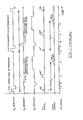
- FIGURE 1 depicts a conventional NMR pulse sequence utilized in the spin-warp method of imaging;
- FIGURE 2 is a pulse sequence similar to that in FIG 1. and which is utilized with the methods of the prior art to gather imaging information for constructing computed T1 images;
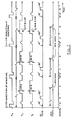
- FIGURE 3 depicts one exemplary embodiment of an interleaved pulse sequence in accordance with the invention for T1 determination;
- FIGURE 4 illustrates another exemplary embodiment of the inventive NMR pulse sequence implemented for four repetition times for determining Tl;
- FIGURE 5 is as yet another exemplary embodiment of the inventive NMR pulse sequence implemented in combination with multiple spin echoes for simultaneous Tl, T2, and Mo determination;
- FIGURE 6 depicts a pulse sequence similar to that in FIG. 5 and which is also used for simultaneous determination of T1, T2 and Mo values; and
- FIGURE 7 depicts still another exemplary embodiment of the invention using the technique of multiple-projection reconstruction to encode spatial information into the NMR signals.
- It will be beneficial to the understanding of the present invention to consider a conventional NMR pulse sequence depicted in FIG. 1. This sequence is the spin-warp version of the two-dimensional Fourier imaging method. The pulse sequence is described, for example, in Kaufman, et al Eds; 'Nuclear Magnetic Resonance Imaging in Medicine," Igaku-Shoin Publishers, 1981.
- Referring now to FIG. 1, it will be seen that in
interval 1, indicated along the horizontal axis, a positive Gz gradient pulse is applied. The direction of the Gz gradient is arbitrarily selected to be in the positive Z-axis direction of the Cartesian coordinate system and coincides with the direction of the Bo magnetic field. The Bo field is not shown in any of the Figures depicting pulses sequences, since it is applied continuously during NMR imaging. Also, ininterval 1, a selected 90° RF pulse is applied in the presence of the Gz gradient so as to excite nuclear spins in a predetermined region of a sample (not shown). Typically, the region is selected to be a narrow slice. In the preferred embodiments, the RF pulse is modulated by a sinc function (sin x/x) so as to preferentially excite nuclear spins in an imaging slice having a substantially rectangular profile. When the G gradient is turned off, the excited spins precess at the same frequency but are out of phase with one another due to the dephasing effect of the gradient. The nuclear spins are rephased by the application ininterval 2 of a negative Gz gradient pulse. Typically, the time integral of the waveform of the G gradient overinterval 2 required to rephase the spins is approximately equal to the negative one half of the time integral of the positive Gz gradient waveform ininterval 1. Duringinterval 3, a phase-encoding Gy gradient is applied simultaneously with the application of a pulsed G gradient. The Gy gradient has a single, peak amplitude in the nth repetition of the sequence comprising intervals 1-5. However, in each successive application, such as the (n+1)th repetition of the sequence (e.g., intervals 6-10, FIG. 1), a different amplitude of the phase-encoding gradient is selected. The Gy gradient encodes spatial information in the Y-axis direction by introducing a twist in the orientation of the transverse magnetization by a multiple of 2π, in the Y-axis direction. Following the application of the first phase-encoding gradient, the transverse magnetization is twisted into a one-turn helix. Each different amplitude of the Gy gradient introduces a different degree of twist (phase encoding). The number of Gy gradient amplitudes is chosen to be equal to the number of pixels (typically 128 or 256) the reconstructed image will have in the Y-axis direction. - The effect of the Gx gradient in
interval 3 is to dephase the nuclear spins by a predetermined amount such that, when a non-selective 180° RF pulse is applied ininterval 4, a spin-echo signal will be produced in interval S. The time of occurrence of the spin-echo signal is determined by the intensity of the Gx gradient applied ininterval 3 and the time the 180° pulse is applied. Spatial information is encoded in the X-axis direction by the application of a linear G gradient ininterval 5 causing the nuclear spins to resonate at frequencies characteristic of their locations with respect to the X-axis. The spin-echo signal is sampled in interval 7 a number of times which is typically equal to the number of pixels (typically 128 or 256) the reconstructed image will have in the X-axis direction. The image pixel values are obtained from the sample signals using a two-dimensional Fourier transform as disclosed, for example, by Kumar et al in J. Mag. Res., Vol. 18, p. 69 (1975). It will be recognized that spin-echo signals are utilized in the preferred embodiment; however, free induction decay (FID) signals may also be utilized. - The pulse sequence described with reference to FIG. 1 may be used to construct an image in which the intensity of each pixel is a complicated function of various tissue-related NMR parameters, such as, spin-lattice (T1) and spin-spin (T2) relaxation times, and the spin-density (Mo) and the pulse sequence timing parameters, such as the sequence-repetition time Tr and the spin-echo time Te. As shown in FIG. 1, the sequence-repetition time is measured between the application of the Gz gradients in
intervals interval 1, and the mean occurrence of the spin-echo ininterval 5 during the nth repetition of the pulse sequence, for example. This sequence is typically repeated enough times (n - 128 or 256) to acquire all of the data necessary to construct an image. This repeated sequence is referred to hereinafter as a "scan." - As described hereinbefore, an image in which the intensity of each pixel depends only on the tissue-related NMR parameters is desirable, since such an image would be easier to interpret. Such images have been produced in the past utilizing, for example, the pulse sequence depicted in FIG. 2 to collect the imaging data. This pulse sequence is substantially identical to that depicted in FIG. 1, but with the exception that additional inverting 180° RF pulses are applied in
intervals intervals interval 5 at Te = Te1, and the second image for the spin-echo signal ininterval 7 at Te = Te2. If I11 is the intensity of a pixel in the first image from the first scan, and 112 is the intensity of the corresponding pixel from the first image of the second scan, then it can be shown that to an approximation:
- It is apparent that Equation (1) can be used to create a computed T1 image by setting the intensity of the corresponding pixel in the computed T1 image in proportion to the approximate T1 value calculated. In this conventional approach for producing computed T1 images, the two intensities I11 and 112 are derived from scans separated in time. That is, as described hereinabove, a first scan is performed with a sequence-repetition time Tr1 and then upon the completion of the first scan, a second scan is performed with a sequence repetition time set to 2Tr1. A drawback associated with this technique is that the approximation of Equation (1) requires that the intensities I11 and I12 represent the same tissue positions. This is a difficult condition to achieve since several minutes are typically required to acquire the NMR image data. During the data-acquisition time, processes, such as cardiac motion, breathing, or peristaltic motion, can cause movement of tissues between the separate scans.
- In accordance with the present invention, the problem of tissue motion between scans is solved by the implementation of the pulse sequence depicted in FIG. 3. Taken individually, portions of the pulse sequence depicted in FIG. 3 (e.g., intervals 1-5, 6-10, 11-15, etc.) are similar to those of the conventional spin-warp sequence described hereinbefore with reference to FIG. I. The manner in which the inventive pulse sequence is implemented to collect NMR imaging data is, however, substantially different. Using the inventive pulse sequence, a single scan is performed using the pulse sequence to acquire data for Tr =Trl and for Tr = Tr2 sequentially, very close in time.
- Referring now to FIG. 3, it will be seen that in the nth repetition of the sequence a spin-echo signal is observed in
interval 5 which is the result of a sequence-repetition time Trl. As part of the nth repetition of the sequence, a second spin-echo signal is observed ininterval 10 for a sequence-repetition time Tr2 which is selected to be different from the time Trl. During the (n+l)th repetition of the sequence, the amplitude of the programmable phase-encoding Gy gradient applied inintervals interval 15 associated with the sequence-repetition time Tr1 is shown. The pulse sequence is repeated n times (to sequence through all amplitudes of gradient Gy), and two spin-echo signals associated with the Tr1 and Tr2 repetition times are observed for each repetition. Two images are to be constructed from the scan, where the signals acquired at Tr = Tr1 (e.g.,intervals 5 and 15) form one image, and the signals from Tr = Tr2 (interval 10) form the second image. Since the data is acquired in an interleaved fashion, alternating the values of Tr between Tr1 and Tr2, the two images produced from the scan will be acquired at nearly the same average time (usually differing only by a few milliseconds) relative to tissue motion. In this manner, tissue motion will be zero or negligible. - A T1 image with reduced motion artifacts can be computed using the data collected with the inventive pulse sequence in the manner described above using the approximate Equation (1) and setting Tr2 = ZTr1· A more accurate relation between T1 and the timing parameters is

- where I1 is the intensity of a pixel in the first image using the spin-echo signal information of
interval 5, FIG. 3, and - I2 is the corresponding pixel in the second image constructed using the spin-echo signal of
interval 10. - The inventive pulse sequence utilizing interleaved sequence-repetition times can be extended to other implementations.
FIQIRE 4 depicts another exemplary embodiment of the invention in which during the nth repetition of a sequencefour different sequence-repetition times Tr1, Tr2, Tr3, and Tr4 are used. Of course, fewer or more repetition times may be selected. For each sequence-repetition time, a corresponding spin-echo signal is observed inintervals -
FIQRE 5 depicts still another embodiment of the inventive NMR pulse sequence including multiple spin-echo generation to create a combined pulse sequence that produces data for computed T1, computed T2, and computed Mo images from a single scan. For instance, during the nth repetition of the sequence, two sequence-repetition times Tr1 and Tr2 are utilized. Additionally, for each sequence-repetition time, two 180° RF pulses are utilized inintervals intervals interval 1. Similarly, sequence-repetition time Tr2, spin-echo signals are observed inintervals intervals -
Image 1 Tr = Tr1' Te Te1' pixel intensity = I11 - Image 2 Tr = Trl, Te = Te2, pixel intensity = I12
- Image 3 Tr = Tr2, Te = Te1, pixel intensity = I21
- Image 4 Tr = Tr2, Te= Te2, pixel intensity = I22
- Computed T1, T2 and/or Mo images utilizing the data obtained with the inventive NMR pulse sequence can be produced using the approximate equations in which it is assumed that Tr2 is equal to 2Tr1. These equations are as follows:


Equation 5, "A" is a scale factor used to convert signal information to spin density. The factor depends on various system electronic gains. Hence, Mo is obtained in relative units but may be determined in terms of density by appropriate calibration. Alternatively, for arbitrary values of Tr1 and Tr2, the exact equations stated below can be solved numerically using conventional techniques, such as multi-parameter chi-square minimization.


- without departing from the spirit of the invention, the pulse sequences can be expanded to include more spin-echo signals and/or more sequence-repetition times to produce increased data for greater accuracy of the computed T1, T2, and/or Mo. For example, it is not necessary for each sequence-repetition time to have multiple spin echoes. Referring to FIG. 6, during the nth repetition of the pulse sequence, two different sequence-repetition times Tr1 and Tr2 are utilized. It will be noted, for example, that with respect to the sequence-repetition time Tr1, only a single spin-echo signal is observed in
interval 5 at a time Te1 following the application of the 90° RF pulse ininterval 1. However, two spin-echo signals are observed inintervals interval 6. Spin-echo delay time Te1 of the spin-echo signal observed ininterval 5 is the same as that of the spin-echo signal observed ininterval 10, although the sequence-repetition times are different. - If, as before, an assumption is made that Tr2 is equal to 2Tr1, then an approximate value for T1 can be calculated using data collected with the sequence of FIG. 6 using the equation:

- Similarly, computed values for T2 and Mo may be obtained using the equations:


- It will be recognized that, with the sequence of FIG. 6, the number of single spin-echo signals with different sequence-repetition times could be greater than two, and the number of echoes in the multi-spin-echo portions of the pulse sequence could also be greater than two. This will give increased accuracy of computed values. As before, in the case of arbitrary values of Tr2 and Trl various numerical techniques known to those skilled in the art can be used to calculate the values of T1, T2, and Mo from more accurate equations similar to Equations (6) - (9).
- The preferred embodiments of the invention have been described hereinabove with reference to the spin-warp-imaging technique. It will be recognized, however, by those of ordinary skill in the art that the invention may be advantageously practiced with other pulse sequences. One example of such a pulse sequence is the multiple-angle-projection-reconstruction pulse sequence depicted in FIG. 7 which is similar in many respects to that of FIG. 3. As in FIG. 3, a single scan is performed with the sequence of FIG. 7 to acquire data for, in this case, two sequence-repetition times Tr1 and Tr2 during each repetition of the pulse sequence. The spin-echo signals observed in
intervals intevals - The primary difference between the pulse sequence of FIG. 7 and that of FIG. 3 is in the manner in which spatial information is encoded into the spin-echo signals. This difference will be described in an exemplary manner with reference to the spin-echo signal observed in
interval 4. The description is, however, equally applicable to the spin-echo signals observed inintervals interval 2 is not a phase-encoding gradient but is, rather, a gradient pulse used in combination with the positive G gradient pulse also ininterval 2 to time the occurrence of the spin-echo signal ininterval 4. To encode spatial information into the spin-echo signal, linear G and Gx gradients are applied duringinterval 4. The Gx and Gy gradients are directed, respectively, in the X- and Y-axis directions within the imaging slice. The magnitudes of the Gx and Gy gradients ininterval 4 determine theprojection angle 8. The magnitude of the Gx gradient is made proportional to the sine of the projection angle, while the magnitude of the Gy gradient is made proportional to the cosine of the projection angle. The G and Gy gradients add vectorially to produce a resultant gradient in the imaging plane at a directon 0. Nuclear spins situated along the direction of the resultant gradient experience different magnetic fields and, therefore, resonate at different frequencies which may be ascertained in a well-known manner by Fourier transformation of the spin-echo signal. Fourier transformation of the signal yields the magnitude of the signal at each frequency and, therefore, at each location with respect to the directon of the gradient. The nuclei situated along each line perpendicular to the direction of the gradient have the same resonant frequency. In successive applications (such as the [n+llth repetition of the sequence), as is necessary in order to obtain sufficient information to image an entire slice, multiple projections are obtained by changingprojection angle 8 by an amount Δ θ, typically of the order of 1°, to collect spatial information from 180 projections in at least a 180° arc. - It will be recognized that the pulse sequence depicted in FIG. 7 is the simplest embodiment of the invention utilizing the multiple-angle-projection-reconstruction technique. This pulse sequence can be modified in the manner previously described with reference to FIG. 4 to collect data for more than two sequence-repetition times Tr. Without limiting the number or types of modifications which may be made, the pulse sequence of FIG. 7 may additionally be modified in the manner previously described with reference to FIGS. 5 and 6 which utilize single and multiple spin-echo signals within each repetition of the sequence to create a combined sequences that produce sufficient data for computed Tl, computed T2, and computed Mo images from a single scan.
- While this invention has been described with reference to particular embodiments and examples, other modifications and variations will occur to those skilled in the art in view of the above teachings. Accordingly, it should be understood that within the scope of the appended claims the invention may be practiced otherwise than is specifically described.
Equation (2) may be solved for other values of Tr1 and TrZ (i.e., when Tr2 does not equal ZTrl) using conventional numerical techniques, such as chi-square minimization.
Claims (9)
1. An NMR method of imaging a predetermined region of a sample positioned in a homogeneous magnetic field, which method comprises:
subjecting said predetermined region, in the course of a complete scan to obtain imaging data to image said region, to a plurality of repetitions of a sequence composed of rotating magnetic field and magnetic-field-gradient pulses, each repetition of said sequence including at least two steps of exciting nuclear spins in said region so as to produce a corresponding number of NMR signals, said steps of exciting being separated by a sequence repetition time Tr; and
sampling each of said NMR signals in the presence of at least one magnetic-field gradient for encoding spatial information into said NMR signals to obtain said imaging data, wherein each repetition of said sequence includes at least two different Tr times, such that said NMR signals are sampled at approximately the same average time relative to any motion of said sample.
2. The method of Claim 1 wherein said steps of exciting each comprise subjecting said predetermined region in the presence of a magnetic-field gradient to a magnetic field rotating at substantially the Larmor frequency so as to preferentially excite nuclear spins in said region, said NMR signals occurring at a time Te measured between the mean application of said rotating magnetic field and the mean occurrence of said NMR signal.
3. The method of Claim 2 wherein said rotating magnetic field comprises a selective 90° RF pulse.
4. The method of Claim 2 wherein said step of exciting further comprises the step of producing at least one spin-echo signal within each sequence-repetition time Tr, each spin-echo signal occurring at a different time Te.
5. The method of Claim 4 wherein said step of producing a spin-echo signal comprises irradiating said region with a 1800 RF pulse.
6. The method of Claim 5 wherein said magnetic-field gradient for encoding spatial information is selected to have one of a plurality of directions within said predetermined region for each repetition of said sequence.
7. The method of Claim 6 wherein said gradient for encoding spatial information comprises a resultant magnetic-field gradient of the vectorial addition of at least two magnetic-field gradients, which gradients are perpendicular to one another within said predetermined region.
8. The method of Claim 5 further comprising the step of applying a variable amplitude magnetic-field gradient having one of a plurality of programmable amplitudes for each repetition of said sequence to encode spatial information into said NMR signals.
9. The method of Claim 8 wherein said NMR signals are sampled in the presence of a substantially linear magnetic-field gradient, which gradient is perpendicular to the direction of said variable amplitude gradient within said predetermined region.
Applications Claiming Priority (2)
| Application Number | Priority Date | Filing Date | Title |
|---|---|---|---|
| US06/500,666 US4549140A (en) | 1983-06-03 | 1983-06-03 | Method utilizing combined, interleaved pulse sequences for reducing motion artifacts in computed T1,T2 and M0 NMR imaging |
| US500666 | 1983-06-03 |
Publications (2)
| Publication Number | Publication Date |
|---|---|
| EP0127850A2 true EP0127850A2 (en) | 1984-12-12 |
| EP0127850A3 EP0127850A3 (en) | 1987-05-27 |
Family
ID=23990419
Family Applications (1)
| Application Number | Title | Priority Date | Filing Date |
|---|---|---|---|
| EP84105929A Withdrawn EP0127850A3 (en) | 1983-06-03 | 1984-05-24 | Method utilizing combined, interleaved pulse sequences for reducing motion artifacts in computed t1, t2 and m0 nmr imaging |
Country Status (5)
| Country | Link |
|---|---|
| US (1) | US4549140A (en) |
| EP (1) | EP0127850A3 (en) |
| JP (1) | JPS6047945A (en) |
| FI (1) | FI841447A (en) |
| IL (1) | IL71472A0 (en) |
Cited By (12)
| Publication number | Priority date | Publication date | Assignee | Title |
|---|---|---|---|---|
| EP0130479A2 (en) * | 1983-06-30 | 1985-01-09 | General Electric Company | Method of projection reconstruction imaging with reduced sensitivity to motion-related artifacts |
| EP0132336A2 (en) * | 1983-07-21 | 1985-01-30 | The Regents Of The University Of California | Method and apparatus for enhanced T1 NMR measurements using repetition intervals TR related to one another by integer multiples |
| EP0188006A2 (en) * | 1985-01-07 | 1986-07-23 | General Electric Company | Method for reversing residual transverse magnetization due to phase-encoding magnetic field gradients,and apparatus |
| EP0205199A1 (en) * | 1985-05-22 | 1986-12-17 | Koninklijke Philips Electronics N.V. | Method of reducing artefacts into images formed by means of nuclear-spin tomography |
| EP0217196A2 (en) * | 1985-09-30 | 1987-04-08 | The Regents Of The University Of California | Apparatus and method for initially capturing most significant low spatial frequency NMR imaging data |
| EP0218838A2 (en) * | 1985-08-16 | 1987-04-22 | General Electric Company | Method and apparatus for reducing image artifacts due to periodic signal variations in NMR imaging |
| FR2590025A1 (en) * | 1985-11-12 | 1987-05-15 | Thomson Cgr | NUCLEAR MAGNETIC RESONANCE IMAGING APPARATUS |
| EP0228129A1 (en) * | 1985-12-20 | 1987-07-08 | Koninklijke Philips Electronics N.V. | Magnetic resonance imaging (MRI) method and device for reducing movement artefacts |
| US4684892A (en) * | 1985-04-22 | 1987-08-04 | Siemens Aktiengesellschaft | Nuclear magnetic resonance apparatus |
| EP0264442A1 (en) * | 1986-05-05 | 1988-04-27 | Univ Duke | Interleaved pulse sequence for nmr image acquisition. |
| EP0414318A2 (en) * | 1989-08-24 | 1991-02-27 | Philips Electronics North America Corporation | Multimode magnetic resonance fast imaging method |
| AU757485B2 (en) * | 2000-03-03 | 2003-02-20 | Schlumberger Technology B.V. | Technique to achieve high resolution estimates of petrophysical properties |
Families Citing this family (17)
| Publication number | Priority date | Publication date | Assignee | Title |
|---|---|---|---|---|
| JPS6024463A (en) * | 1983-07-20 | 1985-02-07 | Toshiba Corp | Nuclear magnetic resonance imaging method |
| DE3570135D1 (en) * | 1984-08-01 | 1989-06-15 | Siemens Ag | Apparatus for producing images of an object under examination |
| US4612504A (en) * | 1984-11-21 | 1986-09-16 | General Electric Company | Method for removing the effects of baseline error components in NMR imaging applications |
| US4695800A (en) * | 1985-06-06 | 1987-09-22 | Technicare Corporation | Non harmonic NMR spin echo imaging |
| US4667159A (en) * | 1985-06-10 | 1987-05-19 | General Electric Company | Method of, and apparatus for, minimizing magnetic resonance imaging artifacts due to power line interference |
| US4728890A (en) * | 1985-08-16 | 1988-03-01 | Picker International, Inc. | Motion artifact suppression technique of magnetic resonance imaging |
| US4706026A (en) * | 1985-08-16 | 1987-11-10 | General Electric Company | Method for reducing image artifacts due to periodic signal variations in NMR imaging |
| US4697149A (en) * | 1985-11-04 | 1987-09-29 | Wisconsin Alumni Research Foundation | NMR flow imaging using a composite excitation field and magnetic field gradient sequence |
| US4746863A (en) * | 1985-11-07 | 1988-05-24 | The Regents Of The University Of California | Contiguous slices in multi-slice MRI |
| JPS62139641A (en) * | 1985-12-16 | 1987-06-23 | 横河メディカルシステム株式会社 | Nmr imaging apparatus |
| US4734646A (en) * | 1986-09-16 | 1988-03-29 | Fonar Corporation | Method for obtaining T1-weighted and T2-weighted NMR images for a plurality of selected planes in the course of a single scan |
| US5227725A (en) * | 1990-11-29 | 1993-07-13 | The United States Of America As Represented By The Secretary Of The Navy | Nuclear magnetic resonance imaging with short gradient pulses |
| US5387866A (en) * | 1993-08-12 | 1995-02-07 | General Electric Company | Methods for high-speed measurement of spin-lattice relaxation times |
| CA2341812A1 (en) * | 2000-03-24 | 2001-09-24 | National Research Council Of Canada | Magnetic resonance spectroscopic imaging with a variable repetition time in conjunction with a variable data acquistion time |
| US6650114B2 (en) * | 2001-06-28 | 2003-11-18 | Baker Hughes Incorporated | NMR data acquisition with multiple interecho spacing |
| JP4494937B2 (en) * | 2004-11-08 | 2010-06-30 | ジーイー・メディカル・システムズ・グローバル・テクノロジー・カンパニー・エルエルシー | MRI equipment |
| WO2013154834A1 (en) * | 2012-04-11 | 2013-10-17 | Dignity Health | System and method for magnetic resonance imaging using three-dimensional, distributed, non-cartesian sampling trajectories |
Citations (1)
| Publication number | Priority date | Publication date | Assignee | Title |
|---|---|---|---|---|
| EP0074022A1 (en) * | 1981-09-07 | 1983-03-16 | Siemens Aktiengesellschaft | Apparatus for nuclear spin tomography |
Family Cites Families (7)
| Publication number | Priority date | Publication date | Assignee | Title |
|---|---|---|---|---|
| GB1584950A (en) * | 1978-05-25 | 1981-02-18 | Emi Ltd | Imaging systems |
| DE3162208D1 (en) * | 1980-03-14 | 1984-03-22 | Nat Res Dev | Methods of producing image information from objects |
| US4475084A (en) * | 1981-01-15 | 1984-10-02 | Picker International Limited | Nuclear magnetic resonance detector |
| US4471306A (en) * | 1982-02-03 | 1984-09-11 | General Electric Company | Method of NMR imaging which overcomes T2 * effects in an inhomogeneous static magnetic field |
| US4484138A (en) * | 1982-07-01 | 1984-11-20 | General Electric Company | Method of eliminating effects of spurious free induction decay NMR signal caused by imperfect 180 degrees RF pulses |
| US4443760A (en) * | 1982-07-01 | 1984-04-17 | General Electric Company | Use of phase alternated RF pulses to eliminate effects of spurious free induction decay caused by imperfect 180 degree RF pulses in NMR imaging |
| US4516075A (en) * | 1983-01-04 | 1985-05-07 | Wisconsin Alumni Research Foundation | NMR scanner with motion zeugmatography |
-
1983
- 1983-06-03 US US06/500,666 patent/US4549140A/en not_active Expired - Fee Related
-
1984
- 1984-04-09 IL IL71472A patent/IL71472A0/en unknown
- 1984-04-11 FI FI841447A patent/FI841447A/en not_active Application Discontinuation
- 1984-05-24 EP EP84105929A patent/EP0127850A3/en not_active Withdrawn
- 1984-05-30 JP JP59108735A patent/JPS6047945A/en active Pending
Patent Citations (1)
| Publication number | Priority date | Publication date | Assignee | Title |
|---|---|---|---|---|
| EP0074022A1 (en) * | 1981-09-07 | 1983-03-16 | Siemens Aktiengesellschaft | Apparatus for nuclear spin tomography |
Non-Patent Citations (1)
| Title |
|---|
| RADIOLOGY, vol. 146, January 1983, pages 123-128, Easton, US; L.E. CROOKS et al.: "Clinical efficiency of nuclear magnetic resonance imaging" * |
Cited By (20)
| Publication number | Priority date | Publication date | Assignee | Title |
|---|---|---|---|---|
| EP0130479A3 (en) * | 1983-06-30 | 1986-04-23 | General Electric Company | Method of projection reconstruction imaging with reduced sensitivity to motion-related artifacts |
| EP0130479A2 (en) * | 1983-06-30 | 1985-01-09 | General Electric Company | Method of projection reconstruction imaging with reduced sensitivity to motion-related artifacts |
| EP0132336A2 (en) * | 1983-07-21 | 1985-01-30 | The Regents Of The University Of California | Method and apparatus for enhanced T1 NMR measurements using repetition intervals TR related to one another by integer multiples |
| EP0132336A3 (en) * | 1983-07-21 | 1986-12-30 | The Regents Of The University Of California | Method and apparatus for enhanced t1 nmr measurements using repetition intervals tr related to one another by integer multiples |
| EP0188006A2 (en) * | 1985-01-07 | 1986-07-23 | General Electric Company | Method for reversing residual transverse magnetization due to phase-encoding magnetic field gradients,and apparatus |
| EP0188006A3 (en) * | 1985-01-07 | 1987-05-27 | General Electric Company | Method for reversing residual transverse magnetization due to phase-encoding magnetic field gradients |
| US4684892A (en) * | 1985-04-22 | 1987-08-04 | Siemens Aktiengesellschaft | Nuclear magnetic resonance apparatus |
| EP0205199A1 (en) * | 1985-05-22 | 1986-12-17 | Koninklijke Philips Electronics N.V. | Method of reducing artefacts into images formed by means of nuclear-spin tomography |
| EP0218838A2 (en) * | 1985-08-16 | 1987-04-22 | General Electric Company | Method and apparatus for reducing image artifacts due to periodic signal variations in NMR imaging |
| EP0218838A3 (en) * | 1985-08-16 | 1987-09-02 | General Electric Company | Method for reducing image artifacts due to periodic signal variations in nmr imaging |
| EP0217196A3 (en) * | 1985-09-30 | 1989-01-18 | The Regents Of The University Of California | Apparatus and method for initially capturing most significant low spatial frequency nmr imaging data |
| EP0217196A2 (en) * | 1985-09-30 | 1987-04-08 | The Regents Of The University Of California | Apparatus and method for initially capturing most significant low spatial frequency NMR imaging data |
| EP0227512A1 (en) * | 1985-11-12 | 1987-07-01 | General Electric Cgr S.A. | Nuclear magnetic resonance imaging apparatus |
| FR2590025A1 (en) * | 1985-11-12 | 1987-05-15 | Thomson Cgr | NUCLEAR MAGNETIC RESONANCE IMAGING APPARATUS |
| EP0228129A1 (en) * | 1985-12-20 | 1987-07-08 | Koninklijke Philips Electronics N.V. | Magnetic resonance imaging (MRI) method and device for reducing movement artefacts |
| EP0264442A1 (en) * | 1986-05-05 | 1988-04-27 | Univ Duke | Interleaved pulse sequence for nmr image acquisition. |
| EP0264442A4 (en) * | 1986-05-05 | 1990-06-27 | Univ Duke | Interleaved pulse sequence for nmr image acquisition. |
| EP0414318A2 (en) * | 1989-08-24 | 1991-02-27 | Philips Electronics North America Corporation | Multimode magnetic resonance fast imaging method |
| EP0414318A3 (en) * | 1989-08-24 | 1992-06-03 | North American Philips Corporation | Multimode magnetic resonance fast imaging method |
| AU757485B2 (en) * | 2000-03-03 | 2003-02-20 | Schlumberger Technology B.V. | Technique to achieve high resolution estimates of petrophysical properties |
Also Published As
| Publication number | Publication date |
|---|---|
| FI841447A (en) | 1984-12-04 |
| IL71472A0 (en) | 1984-07-31 |
| FI841447A0 (en) | 1984-04-11 |
| US4549140A (en) | 1985-10-22 |
| JPS6047945A (en) | 1985-03-15 |
| EP0127850A3 (en) | 1987-05-27 |
Similar Documents
| Publication | Publication Date | Title |
|---|---|---|
| US4549140A (en) | Method utilizing combined, interleaved pulse sequences for reducing motion artifacts in computed T1,T2 and M0 NMR imaging | |
| US4549139A (en) | Method of accurate and rapid NMR imaging of computed T1 and spin density | |
| US4532473A (en) | NMR method for measuring and imaging fluid flow | |
| US4734646A (en) | Method for obtaining T1-weighted and T2-weighted NMR images for a plurality of selected planes in the course of a single scan | |
| EP0098426B1 (en) | Method of eliminating effects of spurious free induction decay nmr signal caused by imperfect 180 degrees rf pulses | |
| US4570119A (en) | Method for visualization of in-plane fluid flow by proton NMR imaging | |
| US4665365A (en) | Method for reversing residual transverse magnetization due to phase-encoding magnetic field gradients | |
| US4318043A (en) | Method and apparatus for rapid NMR imaging of nuclear densities within an object | |
| US4715383A (en) | Method for reducing artifacts in NMR images | |
| EP0115642A2 (en) | NMR scanner with motion zeugmatography | |
| EP0144871A2 (en) | Method and apparatus for selective NMR imaging of chemically-shifted nuclei | |
| US4731583A (en) | Method for reduction of MR image artifacts due to flowing nuclei by gradient moment nulling | |
| US4654595A (en) | Method of analyzing properties of a matter or a magnetic field | |
| US4587489A (en) | Method for rapid acquisition of NMR data | |
| GB2320576A (en) | A multi-echo Dixon water and fat separation sequence | |
| US5051699A (en) | Magnetic resonance imaging system | |
| US5300886A (en) | Method to enhance the sensitivity of MRI for magnetic susceptibility effects | |
| US4654591A (en) | NMR flow imaging using bi-phasic excitation field gradients | |
| US5499629A (en) | Slice profile stabilization for segmented k-space magnetic resonance imaging | |
| US4697149A (en) | NMR flow imaging using a composite excitation field and magnetic field gradient sequence | |
| US4855679A (en) | Magnetic resonance studies of restricted volumes | |
| EP0527462B1 (en) | Magnetic resonance imaging method and system capable of measuring short "T2" signal components | |
| US4982160A (en) | Method and system for controlling magnetic resonance signal acquisition sequence | |
| USRE33279E (en) | Method for rapid acquisition of NMR data | |
| de Lange et al. | Basic MR Physics |
Legal Events
| Date | Code | Title | Description |
|---|---|---|---|
| PUAI | Public reference made under article 153(3) epc to a published international application that has entered the european phase |
Free format text: ORIGINAL CODE: 0009012 |
|
| AK | Designated contracting states |
Designated state(s): CH DE FR GB LI NL SE |
|
| 17P | Request for examination filed |
Effective date: 19850411 |
|
| PUAL | Search report despatched |
Free format text: ORIGINAL CODE: 0009013 |
|
| AK | Designated contracting states |
Kind code of ref document: A3 Designated state(s): CH DE FR GB LI NL SE |
|
| STAA | Information on the status of an ep patent application or granted ep patent |
Free format text: STATUS: THE APPLICATION HAS BEEN WITHDRAWN |
|
| 18W | Application withdrawn |
Withdrawal date: 19880302 |
|
| RIN1 | Information on inventor provided before grant (corrected) |
Inventor name: MACFALL, JAMES RUSSELL |