EP0122578B1 - Fatigue monitoring method of components, for example in a nuclear power station - Google Patents
Fatigue monitoring method of components, for example in a nuclear power station Download PDFInfo
- Publication number
- EP0122578B1 EP0122578B1 EP84103962A EP84103962A EP0122578B1 EP 0122578 B1 EP0122578 B1 EP 0122578B1 EP 84103962 A EP84103962 A EP 84103962A EP 84103962 A EP84103962 A EP 84103962A EP 0122578 B1 EP0122578 B1 EP 0122578B1
- Authority
- EP
- European Patent Office
- Prior art keywords
- memory
- stress
- computing unit
- component
- stored
- Prior art date
- Legal status (The legal status is an assumption and is not a legal conclusion. Google has not performed a legal analysis and makes no representation as to the accuracy of the status listed.)
- Expired
Links
Images


Classifications
-
- G—PHYSICS
- G07—CHECKING-DEVICES
- G07C—TIME OR ATTENDANCE REGISTERS; REGISTERING OR INDICATING THE WORKING OF MACHINES; GENERATING RANDOM NUMBERS; VOTING OR LOTTERY APPARATUS; ARRANGEMENTS, SYSTEMS OR APPARATUS FOR CHECKING NOT PROVIDED FOR ELSEWHERE
- G07C3/00—Registering or indicating the condition or the working of machines or other apparatus, other than vehicles
Definitions
- the invention relates to a method for monitoring the fatigue of preferably thermally and / or mechanically loaded components, such as. B. in nuclear power plants or aircraft, with sensors attached to the outside of the monitored components.
- the object of the invention is to provide a method for monitoring the fatigue of components, for. B. in a nuclear power plant to create a continuous, based on actual measurement data operational monitoring.
- this object is achieved by a method according to claim 1, which is characterized on the one hand in that the measured values measured by sensors on the components to be monitored arrive in a certain time cycle at a process computer which contains a first computing unit which records the measured course of the measured values dissolves into uniform elementary courses charged with different weighting factors and stores them in a first memory such that a superposition of these preferably triangular elementary courses weighted with the weighting factors approximates the actually measured course of the respective measured values, so that the values stored in a second memory for the elementary voltage profiles generated from these elementary profiles of the measured values are called up from these elementary profiles of the measured values and weights in a second arithmetic unit by superimposing them with the above-mentioned weighting factors
- the elementary voltage curves approximate the actual voltage curve and are stored in a third memory, and that a third arithmetic unit calculates the partial utilization factor of the component resulting from an evaluation cycle from this stored, approximate voltage curve using voltage-dependent fatigue curves and outputs it to a fourth memory in which
- a component for example a feed water nozzle in a nuclear power plant.
- the corresponding temperature profiles inside this component are now calculated (temperature backward analysis).
- the tensile stress profiles in the wall material of the component can be calculated.
- mechanical measurement values measured on the component can also be converted into partial utilization rates.
- Advertisements during ultrasound tests can be tracked continuously.
- This monitoring also makes it possible to carry out repair measures that are necessary in a targeted and thus economical manner.
- the operational monitoring system enables e.g. B. for all areas in power plants a more precise and, above all, more economical implementation of stress and fatigue analyzes.
- the invention is applicable not only in the power plant area described by way of example, but also in other areas. Another example is the fatigue check of aircraft components etc.
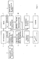
- Figure 1 shows a flow diagram for the method for monitoring the fatigue of components in a nuclear power plant.
- the basis for the fatigue analysis is the material-specific, empirically determined fatigue curve, e.g. B.
- Fig. 2 shows.
- the individual reference stress ranges ⁇ v are assigned the maximum permissible number N of load changes.
- the material fatigue caused by n equal load change fluctuations is determined by the "utilization factor" expressed.
- the total utilization factor Ug of formula gives it j as the sum of the individual partial utilization factors U according to
- n in each case, based on the associated reference stress change ⁇ i , the number of load changes actually occurring, and N ; the maximum number of load changes resulting from the curve according to FIG. 2.
- the temperatures are measured using suitable sensors (13), which in the example are arranged on a pipe section (14).
- the monitoring device according to the invention makes use of a particularly simple calculation of the voltage distribution, which is therefore described in detail below:
- the invention makes use of this superposition principle in that it approximates complex temperature profiles from elementary triangular temperature profiles, so-called “elementary transients”, according to a modular principle.
- An attempt is made to present the externally measured temperature curve R (boundary condition) as a superposition of appropriately weighted elementary transients T l l ... T n '(FIG. 6) of the inner surface surface temperatures R of the inner surface, ie The temperature field T belonging to the surface temperature R is then approximately through given.
- the elementary transients T i which are used here are due to the temperature profile occurring on the inside of the corresponding component (for example a pipe section (14) according to FIG. 3) defined as shown in Figs. 4 and 5.
- i denotes the point on the inside opposite the measuring point i
- E (I) the temperature profile on the inside
- (x, t) the dependence on the coordinates of place and time.
- FIG. 6 shows how a uniform, piece-wise linear internal temperature curve T (I) (represented by a continuous line), by means of superposition, elementary transients shifted in time and differently weighted
- T j (1) , T 2 (I) , T3 (I) , T 4 (I) can be obtained, the courses of which have the shape of simple triangles on the inside, as shown in FIG. 4.
- the “response” to an elementary transient T E (I) at point x on the inside of a component is the temperature curve E (A) according to FIG. 8 in the opposite Point y on the outside, and by superposition of the “answers” T 1 (A) -T 4 (A) according to FIG. 9, an “answer” to the temperature profile according to FIG.
- the temperature-backward analysis mentioned uses a measured outside temperature curve to determine the corresponding inside temperature curve according to the following scheme:
- the outside temperature T (A) is approximately represented as a superposition of answers E i (A), i.e. of elementary curves or elementary transients for the outer surface at location i :
- the measured curve of the outside temperature would be replaced by a large number of overlapping, time-shifted and differently weighted triangular element temperature curves.
- the individual weightings r j are determined in such a way that the best possible approximation to the actually measured profile of the outside temperature is achieved.
- Equation (8) can be described as follows:
- D is a linear differential operator. As is known, this system can be uniquely solved with given displacements or given forces in the peripheral area, taking into account the body balance conditions.
- weightings of the individual elementary transients determined in the temperature backward analysis explained with reference to FIGS. 4 to 9 can also be used directly when the individual voltage profiles are superimposed.
- the relevant weighting factors for the individual temperature transients determined in the temperature backward analysis are determined in block 2 in accordance with the flow diagram shown in FIG. 1.
- the elementary reference stress curves corresponding to the elementary transients T of the temperature of the inner surface are stored in the block-specific stress file for unit load cases, block 3 in FIG. 1. From this voltage file for unit load cases, the reference voltage curves stored for the respective temperature transient, specific to the module, are called up and multiplied in block 2 by the associated weighting factors. In block 4, the elementary voltage curves called up in the voltage file 3 and weighted in block 2 are followed by Superposition of the actual voltage curve determined.
- the degree of utilization is calculated in block 5 with the aid of a specific algorithm.
- This algorithm is known as the "rainflow" or reservoir algorithm. It is essentially based on the fact that the determined voltage curve is broken down into a finite number of simple-period processes. (See K. Roik, lectures on steel construction, Wilhelm Ernst and Son Verlag, 1978, p. 69). A material-dependent partial utilization factor is stored in a memory FAT for each of these processes.
- the partial utilization factor U to be applied for the individual periodic elementary cycle is then obtained in block 5 using the rainflow algorithm ; , which is included in the determination of the total utilization factor according to equation (2).
- the result is the cumulative time profile of the overall degree of utilization, which is transferred to peripheral devices.
- the part of the fatigue monitoring of a certain component described up to now by continuously updating the degree of utilization can be summarized as follows: On the basis of the measurement data that record the outside temperatures, the internal temperatures are first calculated back; the internal temperature curve is broken down into weighted "elementary transients". The individual elementary transients obtained when the temperature profile is divided are individually assigned voltage transients previously calculated from a file and superimposed on a voltage profile. From the superposed stress curve, partial degrees of utilization and the degree of utilization are calculated from the rainflow method using predefined fatigue curves. The replacement of the monitored component can be planned in good time before the overall degree of utilization reaches its highest permissible limit, namely the value 1.
- the corresponding load cases are identified in block 8 on the basis of various system-specific operating signals, which can essentially be seen in the control room 7 in the exemplary embodiment of a nuclear power plant 1.
- Such typical load cases are e.g. For example: slow start-up, rapid shutdown, etc.
- the voltage file shown in block 9 contains the corresponding reference voltage curves. This means: For each load case identified on the basis of certain operating signals or operating signal combinations, the associated voltages are taken from block 9 from the voltage file and compiled in block 10 to form a voltage curve.
- the data that are stored in the voltage file in block 9 have been determined on the basis of theoretical considerations and / or calculations, or have been measured in the past for special load cases. It is a matter of previously known - calculated or measured - voltage profiles for special load cases, from which the voltage profile is composed in block 10.
- the flow of information leads again from block 10 to block 5, where the associated partial utilization rate is calculated from this comparison voltage curve with the aid of the rainflow or reservoir algorithm.
- the calculation of the degree of partial utilization in block 5 by way of blocks 7 to 10, i.e. based on the load case identification and the voltage data determined for identified load cases based on previous processes and / or calculations, thus runs in parallel with the determination of the degree of utilization via the component to be monitored directly measured temperature and other mechanical data and their processing in blocks 2 to 5.
- the operating data are recorded in a block 11 and stored in a data memory, a so-called log book, indicated by block 12 in FIG. 1.
- a data memory a so-called log book, indicated by block 12 in FIG. 1.
- the results of the calculation of the stress distribution in block 4 and the formation of the stress curve in block 10 are continuously compared on the basis of the load case identification in block 8 and that the most unfavorable value is used to determine the degree of utilization to ensure maximum security. This makes it possible to determine the superimposition of voltages for the monitored modules that occurs during certain load cases that can be identified in the load case.
- the data determined in this way can be used to obtain data for module-related, life-extending operating modes of the system.
- the measured values relevant to the subject of the application come from three different sources in a nuclear power plant, namely the temperature sensors 13, 20, the mechanical sensors 15, 21 and the sensors 22, the control room 7, from which the nuclear power plant 1 is controlled.
- the temperature sensors 13, 20 provide the measured values which are required for the temperature backward analysis described above.
- the mechanical sensors 15, 21 stand for such signal transmitters or sensors, which allow information about mechanical stresses, such as. B. measuring instruments for internal pressure, flow rate, level indicators etc.
- the operating signals emanating from the sensors 22 of the control room 7 can be used to determine the current operating state (load case) of the operating system 1 or power plant.
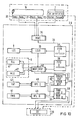
- a first memory FIFO I 37 First In / First Out
- a second memory FIFO II 38 are connected to the unit for measured value acquisition MWE 34 via a data bus 36.
- the data that is first read in time is also read out first in time.
- the memories 37, 38 are buffer memories.
- the first memory 37 is in alternating connection with the computing unit LCID 39 (load case identification), which is used to identify the individual load cases.
- the basis for the identification of the individual load cases are the operating signals coming from the sensors 22 of the control room 7.
- the computing unit LCID 39 determines, based on the load cases identified in this way, from the voltage file for specified load cases LCL 9, comparison voltage values for identified load cases, and component-dependent as well as various weighting factors for these comparison voltage values, which are determined by various sensors, and places them in one of the computing units HSP / VSP 40 for later superposition not represented RAM.
- the temperature and voltage measurement values prepared by the measurement value acquisition MWE 34 go directly to the second memory FIFO II 38 and from there to the voltage file for unit load cases 3, which contains the memory TLL (Thermal Load Library) 41 for thermal load cases and the memory MLL 42 (Mechanical Load Library) for mechanical load cases.
- TLL Thermal Load Library
- MLL 42 Mechanism Load Library
- the computing unit VSP 40 determines the resulting voltage curve by superimposing it and stores it in the STACK HSP VSP 43 memory. This is divided into two storage units 44 and 45 for the main voltages (HSP) and the determined reference voltages (VSP).
- the resulting reference stress curve stored in the memory unit 44 of the working memory STACK HSP VSP 43 is calculated in the third arithmetic unit RFL (rainflow) 46 with the aid of the material-related fatigue curves (cf. FIG. 2) stored in the memory FAT (fatigue) 47 with the rainflow mentioned above. or reservoir algorithm processed.
- the resulting partial utilization levels are added to the utilization level already stored in the RAM USE I 48 memory.
- the crack growth can be calculated.
- these main stresses occurring in the arithmetic unit HSP / VSP are stored in the memory unit STACK HSP 44 of the memory STACK HSP / VSP 43 and retrieved from there by a second arithmetic unit RFL 11 and processed on the basis of the stress-dependent crack growth curves stored in the memory RWK 50.
- the calculation result, the crack growth per load unit is added to the crack lengths previously stored in RAM USE II 51.
- the process computer 30 is connected to the console CO 35, which has the usual peripheral devices (printer, writer, etc.) and can be read in the degree of utilization and the accumulated crack lengths.
- the console 35 which is usually in the control room 7, allows the replacement of components that have been used in foreseeable periods to be planned in good time. It also enables the operating system to be operated in the way that is most gentle on the most vulnerable or most worn components.
Landscapes
- Physics & Mathematics (AREA)
- General Physics & Mathematics (AREA)
- Monitoring And Testing Of Nuclear Reactors (AREA)
- Testing Of Devices, Machine Parts, Or Other Structures Thereof (AREA)
- Investigating Or Analyzing Materials Using Thermal Means (AREA)
- Testing Or Calibration Of Command Recording Devices (AREA)
Description
Die Erfindung betrifft ein Verfahren zur Überwachung der Ermüdung von vorzugsweise thermisch und/oder mechanisch belasteten Bauteilen, wie z. B. solchen in Kernkraftwerken oder Flugzeugen, mit außen an den überwachten Bauteilen angebrachten Sensoren.The invention relates to a method for monitoring the fatigue of preferably thermally and / or mechanically loaded components, such as. B. in nuclear power plants or aircraft, with sensors attached to the outside of the monitored components.
Die seitherige Ermüdungsanalyse für einzelne Bauteile, wie z. B. für einen Speisewasserstutzen in einem Kernkraftwerk, erfolgt aufgrund von Lastfallspezifikationen, die neben thermischen und mechanischen Belastungsdaten Annahmen über die jeweils zu erwartenden Häufigkeiten mechanischer Belastungsfälle enthalten. Der Nachteil einer solchen Spezifikation liegt in den theoretischen Annahmen, die oft nicht mit den im Betrieb durch Messung tatsächlich festgestellten Beanspruchungen übereinstimmen.The since then fatigue analysis for individual components, such as B. for a feed water nozzle in a nuclear power plant, takes place on the basis of load case specifications, which in addition to thermal and mechanical load data contain assumptions about the frequency of mechanical load cases to be expected in each case. The disadvantage of such a specification lies in the theoretical assumptions, which often do not correspond to the stresses actually determined during operation by measurement.
Auf der anderen Seite ist eine genaue Ermüdungsanalyse erwünscht, um möglichst präzise vorhersagen zu können, wann ein bestimmtes Bauteil seinen maximalen Ausnutzungsgrad erreicht hat und demgemäß ausgetauscht werden muß.On the other hand, an exact fatigue analysis is desired in order to be able to predict as precisely as possible when a certain component has reached its maximum degree of utilization and must therefore be replaced.
Aufgabe der Erfindung ist es, ein Verfahren zur Überwachung der Ermüdung von Bauteilen, z. B. in einem Kernkraftwerk, zu schaffen, das eine kontinuierliche, auf tatsächlich anfallende Meßdaten gestützte Betriebsüberwachung ermöglicht.The object of the invention is to provide a method for monitoring the fatigue of components, for. B. in a nuclear power plant to create a continuous, based on actual measurement data operational monitoring.
Erfindungsgemäß wird diese Aufgabe gelöst durch ein Verfahren gemäß Anspruch 1, das einerseits dadurch gekennzeichnet ist, daß die von Sensoren an den zu überwachenden Bauteilen in einem bestimmten Zeittakt gemessenen Meßwerte an einen Prozeßrechner gelangen, der eine erste Recheneinheit enthält, die den gemessenen Verlauf der Meßwerte in einheitliche mit unterschiedlichen Gewichtungsfaktoren beaufschlagte Elementarverläufe auflöst und in einem ersten Speicher abspeichert, derart, daß eine Überlagerung dieser mit den Gewichtungsfaktoren gewichteten vorzugsweise dreieckigen Elementarverläufe eine Annäherung an den tatsächlich gemessenen Verlauf der jeweiligen Meßwerte ergibt, daß die in einem zweiten Speicher gespeicherten Werte für die von diesen Elementarverläufen der Meßwerte erzeugten elementaren Spannungsverläufe von diesen Elementarverläufen der Meßwerte abgerufen werden und in einer zweiten Recheneinheit durch Überlagerung dieser mit den obengenannten Gewichtungsfaktoren gewichteten elementaren Spannungsverläufe der tatsächliche Spannungsverlauf angenähert und in einen dritten Speicher abgespeichert wird, daß ferner eine dritte Recheneinheit aus diesem abgespeicherten, angenäherten Spannungsverlauf unter Verwendung von spannungsabhängigen Ermüdungskurven den sich während eines Auswertungszyklus ergebenden Teilausnutzungsgrad des Bauteils errechnet und an einen vierten Speicher abgibt, in dem der Teilausnutzungsgrad zu dem darin gespeicherten Gesamtausnutzungsgrad hinzuaddiert wird und einen neuen Wert für den Gesamtausnutzungsgrad bildet.According to the invention, this object is achieved by a method according to
Im konkreten Fall bedeutet dies z. B., daß entlang des Umfangs eines Bauteils, beispielsweise eines Speisewasserstutzens in einem Kemkraftwerk, Temperatursensoren angeordnet sind. Aufgrund der örtlichen Temperaturverteilung und/oder des zeitlichen Temperaturverlaufs werden nun die entsprechenden Temperaturverläufe im Inneren dieses Bauteils berechnet (Temperatur-Rückwärts-Analyse). Auf der Grundlage dieser für das Innere des Bauteils errechneten Temperaturen lassen sich rechnerisch die Zugspannungsverläufe im Wandmaterial des Bauteils ermitteln. Dieses an sich sehr komplizierte Verfahren wird dadurch vereinfacht, daß die Berechnungen nicht für den tatsächlich gemessenen Verlauf der Meßwerte erfolgen, sondern für « Elementarverläufe ", sogenannten Elementartransienten, als . deren Überlagerung - bei Verwendung bestimmter Gewichtungsfaktoren - der tatsächlich gemessene Temperaturverlauf näherungseise dargestellt werden kann. Infolge der Linearität des für die Berechnung der Spannungsverläufe aus den Temperaturverläufen geltenden Gleichungssystems läßt sich auch der tatsächlich auftretende Zugspannungsverlauf als entsprechende, d. h. mit denselben Gewichtungsfaktoren versehene Überlagerung elementarer Zugspannungsverläufe darstellen, die den elementaren Temperaturverläufen entsprechen. Der durch diese Überlagerung ermittelte - angenäherte - Vergleichsspannungsverlauf wird dann mit Hilfe des bekannten Rainflow- oder Reservoir-Algorithmus abgearbeitet, d. h. in Teilnutzungsgrade umgerechnet. Auf diese Art lassen sich die während der Auswertungszyklen ergebenden Teilausnutzungsgrade zum jeweiligen neuesten Gesamtausnutzungsgrad, einem für die Ermüdung eines Bauteils charakteristischen Wert, aufaddieren.In the specific case, this means e.g. B. that temperature sensors are arranged along the circumference of a component, for example a feed water nozzle in a nuclear power plant. On the basis of the local temperature distribution and / or the temperature profile over time, the corresponding temperature profiles inside this component are now calculated (temperature backward analysis). On the basis of these temperatures calculated for the interior of the component, the tensile stress profiles in the wall material of the component can be calculated. This method, which is very complicated per se, is simplified in that the calculations are not carried out for the actually measured course of the measured values, but for "elementary courses " , so-called elementary transients, as a superimposition of which - when using certain weighting factors - the actually measured temperature course can be approximated As a result of the linearity of the system of equations used to calculate the stress curves from the temperature curves, the actually occurring tensile stress curve can also be represented as a corresponding, ie provided with the same weighting factors, superimposition of elementary tensile stress curves which correspond to the elementary temperature curves is then processed with the help of the well-known rainflow or reservoir algorithm, ie converted into partial utilization rates Add up the partial utilization levels resulting from the evaluation cycles to the respective latest total utilization level, a characteristic value for the fatigue of a component.
In ähnlicher Weise, wie im vorstehenden Absatz anhand von Temperaturmeßwerten erläutert, lassen sich auch am Bauteil gemessene mechanische Meßwerte in Teilausnutzungsgrade umwandeln.In a similar way, as explained in the preceding paragraph on the basis of temperature measurement values, mechanical measurement values measured on the component can also be converted into partial utilization rates.
Parallel dazu kann andererseits vorgesehen sein, daß neben den unmittelbar an dem zu überwachenden Bauteil abgegriffenen Meßwerten auch Betriebsdaten, die - beispielsweise von einer Warte oder einem Stellpult aus - das Betriebssystem steuern zu dem das zu überwachende Bauteil gehört, zur Lastfallidentifizierung herangezogen werden. Derartige Lastfälle in einem Kernkraftwerk sind beispielsweise « Anfahren », « Schnellabschaltung » usw. Diesen einzelnen Lastfällen kann man nun bestimmteIn parallel, on the other hand, it can be provided that, in addition to the measured values tapped directly on the component to be monitored, operating data which control the operating system to which the component to be monitored belongs, for example from a control room or control panel, are used for load case identification. Such load cases in a nuclear power plant are, for example, «starting», «rapid shutdown» etc. These individual load cases can now be determined
- empirisch festgestellte oder auf der Grundlage von Annahmen berechnete oder geschätzte - Vergleichsspannungsverläufe zuordnen, so daß bei Identifizierung derartiger Lastfälle durch evtl. zusätzliche Überlagerung mit geeignet gewichteten mechanischen Einheitslastfällen ein Vergleichsspannungsverlauf entsteht, der mit Hilfe des Rainflow-Algorithmus ebenfalls wieder in einen Teilausnutzungsgrad umgerechnet werden kann.- Assign empirically determined or calculated or estimated on the basis of assumptions - reference stress curves, so that when identifying such load cases by possible additional superimposition with suitably weighted mechanical standard load cases, a reference stress curve arises, which is also converted back to a partial utilization rate with the help of the rainflow algorithm can.
Die Vorteile des Verfahrens lassen sich wie folgt zusammenfassen :The advantages of the process can be summarized as follows:
Die einheitliche Vorgehensweise führt bei allen Bauteilen zu vergleichbaren Ergebnissen und gibt Hinweise auf kritische Bauteile.The uniform procedure leads to comparable results for all components and provides information on critical components.
Die zeitliche Erfassung der einzelnen Betriebsvorgänge und die kontinuierlichen Temperaturmessungen führen zur genauen Bestimmung der Ausnutzungsgrade.The chronological recording of the individual operating processes and the continuous temperature measurements lead to the exact determination of the degrees of utilization.
Sollte bei der Überwachung eine kritische Tendenz erkannt werden, ist es möglich, rechtzeitig durch eine neu festzulegende Schonfahrweise die Lebensdauer einzelner, gefährdeter Komponenten zu erhöhen.If a critical tendency is identified during the monitoring, it is possible to increase the service life of individual, endangered components in good time through a newly defined gentle driving style.
Anzeigen bei Ultraschall-Prüfungen können gezielt kontinuierlich verfolgt werden.Advertisements during ultrasound tests can be tracked continuously.
Durch die Überwachung des Rißwachstums ist man in der Lage, auch bei der Erreichung der rechnerischen Ausnutzung von 1,0 die Anlage weiter zu betreiben.By monitoring the crack growth, one is able to continue operating the system even when the calculated utilization of 1.0 is reached.
Durch diese Überwachung ist auch ein gezielter und damit wirtschaftlicher Ablauf eventuell erforderlicher Reparaturmaßnahmen möglich.This monitoring also makes it possible to carry out repair measures that are necessary in a targeted and thus economical manner.
Die kontinuierliche Betriebsüberwachung führt zur lückenlosen Betriebsdatenerfassung (Logbuch).Continuous operational monitoring leads to complete operational data acquisition (log book).
Das Betriebsüberwachungssystem ermöglicht z. B. für alle Bereiche in Kraftwerken eine genauere und vor allem auch wirtschaftlichere Durchführung von Spannungs- und Ermüdungsanalysen.The operational monitoring system enables e.g. B. for all areas in power plants a more precise and, above all, more economical implementation of stress and fatigue analyzes.
Die Erfindung ist nicht nur im beispielhaft beschriebenen Kraftwerksbereich, sondern auch in anderen Bereichen anwendbar. Genannt sei als weiteres Beispiel die Überprüfung der Ermüdung von Bauteilen von Flugzeugen etc.The invention is applicable not only in the power plant area described by way of example, but also in other areas. Another example is the fatigue check of aircraft components etc.
Ein Ausführungsbeispiel der Erfindung und ihrer vorteilhaften Weiterbildung wird im folgenden anhand der beigefügten Zeichungen beschrieben.An embodiment of the invention and its advantageous development is described below with reference to the accompanying drawings.
Es stellen dar:
- Fig. 1 ein Ablaufschema des Verfahrens,
- Fig. 2 eine Ermüdungskurve für den Bauteil (materialspezifische Ermüdungskurve),
- Fig. 3 die schematische Anordnung mehrerer Temperatursensoren entlang des äußeren Umfangs eines rohrförmigen Bauteils,
- Fig. 4 den zeitlichen Verlauf einer Elementartransiente,
- Fig. 5 den örtlichen Verlauf einer Elementartransiente,
- Fig. 6 die zeitliche Überlagerung mehrerer gewichteter Elementartransienten,
- Fig. 7 eine weitere Darstellung einer Elementartransiente an einem Punkt x der Innenseite eines Bauteils,
- Fig. 8 der sich daraus als « Antwort ergebende Verlauf der Temperatur in dem dem genannten Punkt x auf der Innenseite gegenüberliegenden Punkt y an der Außenseite,
- Fig. 9 die durch Überlagerung von Antworten gemäß Fig. 8 entstehende Antwort auf überlagerte Elementartransienten nach Fig. 6,
- Fig. 10 ein Blockschaltbild eines Ausführungsbeispiels.
- 1 is a flow chart of the method,
- 2 shows a fatigue curve for the component (material-specific fatigue curve),
- 3 shows the schematic arrangement of a plurality of temperature sensors along the outer circumference of a tubular component,
- 4 shows the time course of an elementary transient,
- 5 shows the local course of an elementary transient,
- 6 shows the temporal superimposition of several weighted elementary transients,
- 7 shows a further illustration of an elementary transient at a point x on the inside of a component,
- 8 the resultant temperature curve in the point y on the outside opposite the point x mentioned on the inside,
- 9 shows the response to superimposed elementary transients according to FIG. 6 resulting from the superimposition of responses according to FIG. 8, FIG.
- Fig. 10 is a block diagram of an embodiment.
Figur 1 zeigt ein Ablaufschema für das Verfahren zur Überwachung der Ermüdung von Bauteilen in einem Kernkraftwerk. Grundlage für die Ermüdungsanalyse ist die materialspezifische, empirisch ermittelte Ermüdungskurve, wie z. B. Fig. 2 zeigt. In ihr ist den einzelnen Vergleichsspannungsschwingbreiten Δσv die jeweils maximal zulässige Anzahl N der Lastwechsel zugeordnet. Die durch n gleiche Lastwechselschwankungen bewirkte Materialermüdung wird durch den «Ausnutzungsgrad " (Usage Factor)![]()
![]()
Für verschiedene Lastwechselschwankungen Δσi ergibt sich der gesamte Ausnutzungsfaktor Uges als Summe der einzelnen Teilausnutzungsfaktoren Uj gemäß der Formel![]()
![]()
Dabei ist n; jeweils, bezogen auf die zugehörige Vergleichsspannungsänderung Δσi, die Anzahl der tatsächlich aufgetretenen Lastwechsel, und N; die sich aus der Kurve nach Figur 2 ergebenden maximale Anzahl von Lastwechseln.Where n ; in each case, based on the associated reference stress change Δσ i , the number of load changes actually occurring, and N ; the maximum number of load changes resulting from the curve according to FIG. 2.
Im einzelnen ergeben sich die Erfordernisse dieser Feststellungen beim Betrieb von Reaktorsystemen aus dem ASME-Code, Sec. III (Stress Categories). Durch das erfindungsgemäße Überwachungsverfahren kann jeweils der Gesamtausnutzungsgrad zu einem bestimmten Zeitpunkt festgestellt werden.In detail, the requirements of these findings when operating reactor systems result from the ASME code, Sec. III (Stress Categories). The overall degree of utilization can be determined at a particular point in time by the monitoring method according to the invention.
Das in Figur 1 symbolisch mit 1 gekennzeichnete Betriebssystem, z. B. ein Kernkraftwerk, gibt bestimmte Meßwerte ab. Es folgt dann im Kästchen 2 die Meßwerterfassung und die Gewichtung der Einheitslastfälle :The operating system symbolically marked with 1 in FIG. 1, e.g. B. a nuclear power plant, gives certain measurements.
Die wichtigsten Meßwerte, aufgrund derer die Spannungsverteilung und daraus dann der Ausnutzungsgrad berechnet wird, sind die Temperaturen, es ist nämlich im allgemeinen - z. B. mangels geeigneter langzeitstabiler Dehnmeßstreifen - nicht möglich, die Spannungsverläufe im Material unmittelbar zu messen und der Bestimmung des Ausnutzungsgrades zugrunde zu legen. Die Berechnung erfolgt deshalb aufgrund einer Temperatur-Rückwärts-Analyse (thermal backward-analysis), die davon ausgeht, daß sich aus den Außentemperaturen, deren zeitlicher und räumlicher Verlauf durch geeignete Sensoren gemessen werden kann, die Temperaturverteilung in der gesamten Struktur und daraus wiederum die Spannungsverteilung berechenbar ist.The most important measured values, on the basis of which the stress distribution and then the degree of utilization are calculated, are the temperatures. B. lack of suitable long-term stable strain gauges - not possible to measure the stress curves in the material directly and to determine the degree of utilization. The calculation is therefore carried out on the basis of a temperature backward analysis, which assumes that the temperature distribution in the entire structure and, in turn, the stress distribution can be calculated from the outside temperatures, the temporal and spatial course of which can be measured by suitable sensors is.
Die Messung der Temperaturen erfolgt dabei, wie schematisch in Fig. 3 dargestellt, mit geeigneten Sensoren (13), die im Beispiel an einem Rohrstück (14) angeordnet sind. Die erfindungsgemäße Überwachungseinrichtung macht sich eine besonders einfache Errechnung der Spannungsverteilung zunutze, die im folgenden daher aus führlich dargestellt wird :As is shown schematically in FIG. 3, the temperatures are measured using suitable sensors (13), which in the example are arranged on a pipe section (14). The monitoring device according to the invention makes use of a particularly simple calculation of the voltage distribution, which is therefore described in detail below:
Allgemein gilt die Wärmeleitungsgleichung![]()
![]()
Wird a als konstant vorausgesetzt und sind T1 und T2 Temperaturfelder, also Lösungen der Gleichung (3), die den Randbedingungen R1 und R2 genügen, so sind sowohl T = T1 + T2 als (für konstantes r) auch T = r · T1 Lösungen von (3), die den Randbedingungen R = R1 + R2 bzw. R = r · R1 genügen.If a is assumed to be constant and T 1 and T 2 are temperature fields, i.e. solutions of equation (3) that satisfy the boundary conditions R 1 and R 2 , then both T = T 1 + T 2 and (for constant r) also T = r · T 1 Solutions of (3) that satisfy the boundary conditions R = R 1 + R 2 or R = r · R 1 .
Die Erfindung macht sich dieses Superpositionsprinzip zunutze, indem sie nach einem Baukastenprinzip komplexe Temperaturverläufe approximativ aus elementaren dreieckigen Temperaturverläufen, sog. « Elementartransienten », zusammensetzt. Dabei wird versucht, den außen gemessenen Temperaturverlauf R (Randbedingung) als Superposition von sich aus geeignet gewichteten Elementartransienten Tl l... Tn' (Fig. 6) der Innenoberfläche ergebenden Oberflächentemperaturen R der Innenoberfläche darzustellen, d. h.![]()
![]()
![]()
![]()
Die Elementartransienten Ti, die hier verwendet werden, sind durch den auf der Innenseite des entsprechenden Bauteils (z. B. eines Rohrabschnittes (14) nach Fig. 3) auftretenden Temperaturverlauf![]()
![]()
In diesen Abbildungen 4 bis 6 bezeichnet i den der Meßstelle i gegenüberliegenden Punkt an der Innenseite, E(I) den Temperaturverlauf an der Innenseite und (x, t) die Abhängigkeit von den Koordinaten Ort und Zeit.In these figures 4 to 6, i denotes the point on the inside opposite the measuring point i, E (I) the temperature profile on the inside and (x, t) the dependence on the coordinates of place and time.
Fig. 6 zeigt wie ein gleichmäßig stückweiser linearer Innentemperaturverlauf T(I) (dargestellt durch eine durchgehende linie), durch Superposition zeitlich gegeneinander verschobener und unterschiedlich gewichteter ElementartransientenFIG. 6 shows how a uniform, piece-wise linear internal temperature curve T (I) (represented by a continuous line), by means of superposition, elementary transients shifted in time and differently weighted
Tj (1), T2 (I), T3(I), T4 (I) gewonnen werden kann, deren Verläufe an der Innenseite die Form einfacher Dreiecke, wie in Fig. 4 dargestellt, haben.T j (1) , T 2 (I) , T3 (I) , T 4 (I) can be obtained, the courses of which have the shape of simple triangles on the inside, as shown in FIG. 4.
Wie aus den Fig. 7 bis 9 ersichtlich, ergibt sich als «Antwort" auf eine Elementartransiente TE (I) in einem Punkt x auf der Innenseite eines Bauteils (Fig.7) der Temperaturverlauf E(A) gemäß Fig. 8 im gegenüberliegenden Punkt y an der Außenseite. Entsprechend läßt sich durch Superposition der « Antworten » T1 (A)-T4 (A) gemäß Fig. 9 eine « Antwort » auf den Temperaturverlauf nach Fig. 6 ermitteln.As can be seen from FIGS. 7 to 9, the “response” to an elementary transient T E (I) at point x on the inside of a component (FIG. 7) is the temperature curve E (A) according to FIG. 8 in the opposite Point y on the outside, and by superposition of the “answers” T 1 (A) -T 4 (A) according to FIG. 9, an “answer” to the temperature profile according to FIG.
Die erwähnte Temperatur-Rückwärts-Analyse ermittelt aus einem gemessenen Außentemperaturverlauf den entsprechenden Innentemperaturverlauf nach folgendem Schema : Zunächst wird die Außentemperatur T(A) näherungsweise als Superposition von Antworten Ei (A) d. h. von Elementarverläufen bzw. Elementartransienten für die Außenoberfläche am Ort i dargestellt :![]()
![]()
Bildlich dargestellt würde der gemessene Verlauf der Außentemperatur durch eine Vielzahl sich überlagernder zeitlich gegeneinander verschobener und unterschiedlich gewichteter dreieckiger Elementartemperaturverläufe ersetzt. Dabei werden die einzelnen Gewichtungen rj so bestimmt, daß eine möglichst gute Annäherung an den tatsächlich gemessenen Verlauf der Außentemperatur erreicht wird.Pictured, the measured curve of the outside temperature would be replaced by a large number of overlapping, time-shifted and differently weighted triangular element temperature curves. The individual weightings r j are determined in such a way that the best possible approximation to the actually measured profile of the outside temperature is achieved.
Bei dieser Approximation wird der Fehler im quadratischen Mittel minimiert. Mathematisch ausgedrückt bedeutet dies, daß das Integral
Aufgrund der Linearität der Wärmeleitungsgleichung (3) kann jetzt auf den Temperaturverlauf an der Innenseite geschlossen werden :![]()
![]()
Man vergleiche hierzu auch die Figuren 8 mit 7. Aus diesen geht deutlich hevor, wie sich ein angenommener Elementarverlauf der Temperatur an der Rohrinnenwand im Punkte x (Fig. 7) zeitlich verschoben in einen Temperaturverlauf an der Außenwand auswirkt.Also compare FIGS. 8 and 7. From these, it is clear how an assumed elementary profile of the temperature on the inner tube wall at point x (FIG. 7) has a temporally shifted effect on a temperature profile on the outer wall.
Aus der durch den Innentemperaturverlauf eindeutig bestimmten Temperaturverteilung läßt sich nun der zugehörige Spannungszustand nach dem verallgemeinerten Hooke'schen Gesetz wie folgt bestimmen :
Die Materialwerte E, a und µ werden als konstant vorausgesetzt. Löst man die ersten drei Gleichungen nach T auf, faßt die Größen u, v, w sowie die σ's und die τ's zu einem Vektor s zusammen und bezeichnet ferner mit T den Vektor (T, T, T, O, O, O), so läßt sich Gleichung (8) wie folgt umschreiben :![]()
![]()
Dabei ist D ein linearer Differentialoperator. Dieses System ist bekanntlich bei vorgegebenen Verschiebungen oder vorgegebenen Kräften auf dem Randgebiet unter Berücksichtigung der Körpergleichgewichtsbedingungen eindeutig lösbar.D is a linear differential operator. As is known, this system can be uniquely solved with given displacements or given forces in the peripheral area, taking into account the body balance conditions.
Daraus ergibt sich : Läßt sich das Temperaturfeld T gemäß Gleichung (5) als Superposition von Elementartransienten T darstellen und ist für jedes T der daraus resultierende Spannungszustand si bekannt, so läßt sich auch die Gleichung (9) durch Superposition lösen, nämlich in der Form![]()
![]()
Das bedeutet, daß die bei der an Hand der Fig. 4 bis 9 erläuterten Temperatur-Rückwärts-Analyse ermittelten Gewichtungen der einzelnen Elementartransienten sich auch direkt bei der Überlagerung der einzelnen Spannungsverläufe einsetzen lassen. Die maßgeblichen Gewichtungsfaktoren für die bei der Temperatur-Rückwärts-Analyse ermittelten einzelnen Temperaturtransienten werden gemäß dem in Fig. 1 dargestellten Ablaufschema im Block 2 ermittelt.This means that the weightings of the individual elementary transients determined in the temperature backward analysis explained with reference to FIGS. 4 to 9 can also be used directly when the individual voltage profiles are superimposed. The relevant weighting factors for the individual temperature transients determined in the temperature backward analysis are determined in
Die den Elementartransienten T der Temperatur der Innenoberfläche entsprechenden elementaren Vergleichsspannungsverläufe sind in der bausteinspezifischen Spannungsdatei für Einheitslastfälle, in Fig. 1, Block 3 gespeichert. Aus dieser Spannungsdatei für Einheitslastfälle werden die für die jeweilige Temperaturtransiente bausteinspezifisch gespeicherten Vergleichsspannungsverläufe abgerufen und im Block 2 mit den zugehörigen Gewichtungsfaktoren multipliziert. Aus den in der Spannungsdatei 3 abgerufenen, und in Block 2 gewichteten elementaren Spannungsverläufen wird in Block 4 durch Überlagerung der tatsächliche Spannungsverlauf ermittelt.The elementary reference stress curves corresponding to the elementary transients T of the temperature of the inner surface are stored in the block-specific stress file for unit load cases,
Aus diesem so in Block 4 ermittelten Spannungsverlauf wird im Block 5 mit Hilfe eines bestimmten Algorithmus der Ausnutzungsgrad berechnet. Dieser Algorithmus ist als « Rainflow » - oder Reservoir-Algorithmus bekannt. Im wesentlichen basiert er darauf, daß der ermittelte Spannungsverlauf in eine endliche Anzahl einfachperiodischer Vorgänge zerlegt wird. (Vgl. K. Roik, Vorlesungen über Stahlbau, Verlag Wilhelm Ernst und Sohn, 1978, S. 69). Für jedes dieser Vorgänge ist in einem Speicher FAT ein materialabhängiger Teilausnutzungsfaktor abgespeichert.From this voltage curve thus determined in
Aus der für das Bauteil bzw. für das Material geltenden Ermüdungskurve nach Figur 2 ergibt sich dann im Block 5 unter Anwendung des Rainflow-Algorithmus der für den einzelnen periodischen Elementarzyklus anzusetzende Teilausnutzungsfaktor U;, der in die Bestimmung des gesamten Ausnutzungsfaktors nach Gleichung (2) eingeht. In Block 6 fällt das Ergebnis, der aufsummierte zeitliche Verlauf des Gesamtausnutzungsgrades an, der an Periphergeräte transferiert wird.From the fatigue curve according to FIG. 2, which applies to the component or the material, the partial utilization factor U to be applied for the individual periodic elementary cycle is then obtained in
Den bis jetzt beschriebenen Teil der Ermüdungsüberwachung eines bestimmten Bauteils durch laufende Fortschreibung des Ausnutzungsgrades kann man zusammenfassend wie folgt kennzeichnen : Aufgrund der Meßdaten, die die Außentemperaturen erfassen, wird zunächst auf die inneren Temperaturen zurückgerechnet; der innere Temperaturverlauf wird in gewichtete « Elementartransienten » zerlegt. Den bei der Aufteilung des Temperaturverlaufs gewonnenen einzelnen Elementartrasienten werden aus einer Datei vorab gerechnete Spannungstransienten einzeln zugeordnet und zu einem Spannungsverlauf superponiert. Aus dem superponierten Spannungsverlauf werden nach der Rainflow-Methode anhand vorgegebener Ermüdungskurven Teilausnutzungsgrade und daraus der Ausnutzungsgrad errechnet. Rechtzeitig bevor der Gesamtausnutzungsgrad seine oberste zulässige Grenze, nämlich den Wert 1 erreicht, kann der Austausch des überwachten Bauteils geplant werden.The part of the fatigue monitoring of a certain component described up to now by continuously updating the degree of utilization can be summarized as follows: On the basis of the measurement data that record the outside temperatures, the internal temperatures are first calculated back; the internal temperature curve is broken down into weighted "elementary transients". The individual elementary transients obtained when the temperature profile is divided are individually assigned voltage transients previously calculated from a file and superimposed on a voltage profile. From the superposed stress curve, partial degrees of utilization and the degree of utilization are calculated from the rainflow method using predefined fatigue curves. The replacement of the monitored component can be planned in good time before the overall degree of utilization reaches its highest permissible limit, namely the
Parallel zu der bis jetzt beschriebenen Ermittlung des Ausnutzungsgrades läuft noch eine zweite Ermüdungsüberwachung für Bauteile ab, deren Beanspruchung nicht oder nur unzureichend durch Außentemperaturmessungen festgestellt werden kann. Anhand verschiedener systemspezifischer Betriebssignale, die im Ausführungsbeispiel eines Kernkraftwerkes 1 im wesentlichen der Warte 7 entnehmbar sind, werden im Block 8 die entsprechenden Lastfälle identifiziert. Solche typischen Lastfälle sind z. B.: Langsames Anfahren, Schnellabschaltung usw. Für derartig indentifizierte Lastfälle enthält die im Block 9 dargestellte Spannungsdatei die entsprechenden Vergleichsspannungsverläufe. Das bedeutet : Aus dem Block 9 werden zu jedem aufgrund bestimmter Betriebssignale oder Betriebssignalkombinationen identifizierten Lastfall die zugehörigen Spannungen aus der Spannungsdatei entnommen und im Block 10 zu einem Spannungsverlauf zusammengestellt. Die Daten, die in der Spannungsdatei im Block 9 gespeichert sind, sind aufgrund theoretischer Überlegungen und/oder Berechnungen ermittelt oder aber in der Vergangenheit bei speziellen Lastfällen gemessen worden. Es handelt sich also um von früher - berechnet oder gemessen - her bekannte Spannungsverläufe für spezielle Lastfälle, aus denen im Block 10 der Spannungsverlauf zusammengesetzt wird. Vom Block 10 führt der Informationsfluß wieder in den Block 5, wo aus diesem Vergleichsspannungsverlauf mit Hilfe der Rainflow- bzw. Reservoir-Algorithmus der zugehörige Teilausnutzungsgrad berechnet wird. Die Berechnung des Teilausnutzungsgrades im Block 5 auf dem Wege über die Blöcke 7 bis 10, also aufgrund der Lastfallidentifikation und der für identifizierte Lastfälle aufgrund früherer Abläufe und/oder Berechnungen ermittelten Spannungsdaten läuft also parallel zu der Ermittlung des Ausnutzungsgrades über die direkt am zu überwachenden Bauteil gemessenen Temperatur- und sonstigen mechanischen Daten und ihre Verarbeitung in den Blöcken 2 bis 5.Parallel to the determination of the degree of utilization described so far, a second fatigue monitoring for components is running, the stress of which cannot be determined or can only be inadequately determined by outside temperature measurements. The corresponding load cases are identified in
Sowohl von der Meßwerterfassung im Block 2 als auch von der Lastfallidentifikation im Block 8 her werden die Betriebsdaten in einem Block 11 erfaßt und in einem Datenspeicher, einem sogenannten Logbuch, angedeutet durch Block 12 in Fig. 1, abgespeichert. Ergänzend kann man vorsehen (nicht gezeigt), daß die Ergebnisse der Berechnung der Spannungsverteilung in Block 4 und der Bildung des Spannungsverlaufs in Block 10 auf der Grundlage der Lastfallidentifikation in Block 8 laufend abgeglichen werden und der Ermittlung des Ausnutzungsgrades der jeweils ungünstigste Wert zugrunde gelegt wird, um maximale Sicherheit zu gewährleisten. Hierdurch wird es möglich, die während bestimmter, der Lastfallidentifikation entnehmbarer Lastfälle auftretende Überlagerungen von Spannungen für die überwachten Bausteine zu ermitteln.Both from the measured value acquisition in
Aus den so ermittelten Daten lassen sich Daten für bausteinbezogene, lebensdauerverlängernde Betriebsweisen der Anlage gewinnen.The data determined in this way can be used to obtain data for module-related, life-extending operating modes of the system.
Fig. 10 zeigt die schaltungsmäßige Realisierung der Erfindung.10 shows the circuit implementation of the invention.
Die für den Anmeldungsgegenstand relevanten Meßwerte stammen bei einem Kernkraftwerk aus drei verschiedenen Quellen, nämlich den Temperaturfühlern 13, 20, den mechanischen Sensoren 15, 21 sowie den Sensoren 22, der Warte 7, von der aus das Kernkraftwerk 1 gesteuert wird.The measured values relevant to the subject of the application come from three different sources in a nuclear power plant, namely the
Die Temperaturfühler 13, 20 liefern die Meßwerte, die für die oben beschriebene Temperatur-Rückwärts-Analyse benötigt werden. Die mechanischen Sensoren 15, 21 stehen für solche Signalgeber oder Meßfühler, die Aufschlüsse über mechanische Beanspruchungen gestatten, wie z. B. Meßinstumente für Innendruck, Strömungsgeschwindigkeit, Füllstandsanzeigen etc. Die von den Sensoren 22 der Warte 7 ausgehenden Bedienungssignale können zur Feststellung des augenblicklichen Betriebszustandes (Lastfall) des Betriebssystems 1 bzw. Kraftwerkes herangezogen werden.The
Von diesen in Fig. 10 mit 20, 21, 22 bezeichneten drei Einheiten gehen jeweils Leitungen an den Prozeßrechner 33, und zwar nach evtl. erforderlicher A/D-Wandlung an die Einheit zur Meßwerterfassung MWE 34. In der Einheit zur Meßwerterfassung MWE 34 werden die von den Temperatursensoren 13, 20 und den mechanischen Sensoren 15, 21 übermittelten Meßwerte bzw. die von den Sensoren 22 der Warte 7 abgegebenen Betriebssignale aufbereitet, geglättet, klassiert, auf Plausibilität untersucht. In beispielsweise bei der Plausibilitätskontrolle erfaßten unklaren oder kritischen Fällen werden von dort direkt Meldungen an eine sogenannte Konsole CO 35, die in der Warte 7 stehen kann, ausgegeben.From these three units, designated 20, 21, 22 in FIG. 10, lines each go to the
Innerhalb der in Fig. 10 dargestellten Prozeßrechnereinheit sind auf der linken Seite ROM (Read Only . Memory) 'Daten- und Programmspeicher und auf der rechten Seite RAM (Random Access Memory) Arbeitsspeicher eingezeichnet. Mit der Einheit zur Meßwerterfassung MWE 34 sind über einen Datenbus 36 ein erster Speicher FIFO I 37 (First In/First Out) und ein, zweiter Speicher FIFO II 38 verbunden. Die jeweils zeitlich zuerst eingelesenen Daten werden auch zeitlich zuerst ausgelesen. Die Speicher 37, 38 sind Pufferspeicher. Der erste Speicher 37 steht in Wechselverbindung mit der Recheneinheit LCID 39 (Load-Case-Identifikation), die zur Identifizierung der einzelnen Lastfälle dient.Within the process computer unit shown in FIG. 10, data and program memories are drawn on the left side ROM (Read Only. Memory) and RAM (random access memory) main memory on the right side. A first memory FIFO I 37 (First In / First Out) and a second memory FIFO II 38 are connected to the unit for measured
Grundlage für die Identifizierung der einzelnen Lastfälle sind die von den Sensoren 22 der Warte 7 eingehenden Betriebssignale. Die Recheneinheit LCID 39 ermittelt aufgrund der so identifizierten Lastfälle aus der Spannungsdatei für spezifizierte Lastfälle LCL 9 Vergleichsspannungswerte zu identifizierten Lastfällen, und bauteilabhängige sowie durch diverse Sensoren bestimmte Gewichtungsfaktoren für diese Vergleichsspannungswerte und legt diese für die spätere Superposition in einen der Recheneinheit HSP/VSP 40 zugeordneten nicht dargestellen Arbeitsspeicher ab.The basis for the identification of the individual load cases are the operating signals coming from the
Die von der Meßwerterfassung MWE 34 aufbereiteten Temperatur- und Spannungsmeßwerte gelangen direkt in den zweiten Speicher FIFO II 38 und von dort an die Spannungsdatei für Einheitslastfälle 3, die die Speicher TLL (Thermal Load Library) 41 für thermische Lastfälle und den Speicher MLL 42 (Mechanical Load Library) für mechanische Lastfälle beinhaltet. Im Speicher TLL 41 sind diejenigen Vergleichsspannungsverläufe gespeichert, die den einzelnen thermischen Elementartransienten zugeordnet sind. In dem Speicher MLL 42 sind diejenigen Vergleichsspannungsverläufe gespeichert, die den mechanischen Elementartrasienten zugeordnet sind. Unter Benutzung der von der Recheneinheit LCID 39 abgelegten Daten und der für mechanische und thermische Einheitslastfälle in den Speichern MLL bzw. TLL stehenden Spannungswerte ermittelt dann die Recheneinheit VSP 40 (für die Haupt- und Vergleichsspannungen) den resultierenden Spannungsverlauf durch Überlagerung und speichert ihn in dem Speicher STACK HSP VSP 43 ab. Dieser ist in zwei Speichereinheiten 44 und 45 für die Hauptspannungen (HSP) und die ermittelten Vergleichsspannungen (VSP) unterteilt.The temperature and voltage measurement values prepared by the measurement
Der in der Speichereinheit 44 des Arbeitsspeichers STACK HSP VSP 43 gespeicherte resultierende Vergleichsspannungsverlauf wird in der dritten Recheneinheit RFL (Rainflow) 46 mit Hilfe der im Speicher FAT (Fatigue) 47 abgespeicherten materialbahängigen Ermüdungskurven (vgl. Fig. 2) mit dem oben erwähnten Rainflow- oder Reservoir-Algorithmus abgearbeitet. Die dabei anfallenden Teilausnutzungsgrade werden zu dem im Speicher RAM USE I 48 bereits gespeicherten Ausnutzungsgrad aufaddiert.The resulting reference stress curve stored in the
Darüber hinaus kann, ausgehend von einer anderweitig, etwa durch Ultraschallprüfung, gemessenen Rißtiefe an der Innenwand, oder ausgehend von einer etwa aus Erfahrungswerten angenommenen oder postulierten Rißtiefe unter Zugrundelegung der in der Recheneinheit HSP/VSP 40 während des Betriebes des Betriebssystems anfallenden Hauptspannungen, d. h. der in den drei Koordinatenachsen anfallenden Spannungen, das Rißwachstum ausgerechnet werden. Hierzu werden diese in der Recheneinheit HSP/VSP anfallenden Hauptspannungen in der Speichereinheit STACK HSP 44 des Speichers STACK HSP/VSP 43 abgespeichert und von dort von einer zweiten Recheneinheit RFL 11 abgerufen und unter Zugrundelegung der im Speicher RWK 50 abgespeicherten, spannungsabhängigen Rißwachstumskurven abgearbeitet. Das Rechenergebnis, der Rißzuwachs je Belastungseinheit wird den bisher im Speicher RAM USE II 51 gespeicherten Rißlängen hinzuaddiert.In addition, starting from a crack depth on the inner wall measured otherwise, for example by ultrasound testing, or on the basis of a crack depth assumed or postulated based on empirical values, on the basis of the main stresses occurring in the computing unit HSP /
Der Prozeßrechner 30 steht mit der Konsole CO 35 in Verbindung, die die üblichen Peripheriegeräte (Drucker, Schreiber etc.) aufweist und in der Ausnutzungsgrad sowie die aufgelaufenen Rißlängen ablesbar sind. Die meist in der Warte 7 stehende Konsole 35 erlaubt es, rechtzeitig den Ersatz in vohersehbaren Zeiträumen ausgenutzter Bauteile zu planen. Sie ermöglicht es auch, das Betriebssystem so zu fahren, wie das für die am gefährdesten, bzw. am meisten abgenützten Bauteile am schonensten ist.The process computer 30 is connected to the console CO 35, which has the usual peripheral devices (printer, writer, etc.) and can be read in the degree of utilization and the accumulated crack lengths. The console 35, which is usually in the
Claims (8)
Applications Claiming Priority (2)
| Application Number | Priority Date | Filing Date | Title |
|---|---|---|---|
| DE3314181 | 1983-04-19 | ||
| DE19833314181 DE3314181A1 (en) | 1983-04-19 | 1983-04-19 | METHOD FOR MONITORING THE FATIGUE OF COMPONENTS, e.g. IN NUCLEAR POWER PLANTS |
Publications (3)
| Publication Number | Publication Date |
|---|---|
| EP0122578A2 EP0122578A2 (en) | 1984-10-24 |
| EP0122578A3 EP0122578A3 (en) | 1987-04-01 |
| EP0122578B1 true EP0122578B1 (en) | 1989-07-19 |
Family
ID=6196794
Family Applications (1)
| Application Number | Title | Priority Date | Filing Date |
|---|---|---|---|
| EP84103962A Expired EP0122578B1 (en) | 1983-04-19 | 1984-04-09 | Fatigue monitoring method of components, for example in a nuclear power station |
Country Status (6)
| Country | Link |
|---|---|
| US (1) | US4764882A (en) |
| EP (1) | EP0122578B1 (en) |
| JP (1) | JPS59206751A (en) |
| BR (1) | BR8401842A (en) |
| DE (2) | DE3314181A1 (en) |
| ES (1) | ES8703028A1 (en) |
Families Citing this family (47)
| Publication number | Priority date | Publication date | Assignee | Title |
|---|---|---|---|---|
| DE3505818A1 (en) * | 1985-02-20 | 1986-08-21 | Licentia Patent-Verwaltungs-Gmbh, 6000 Frankfurt | MONITORING AND CONTROL DEVICE FOR SWITCHGEAR |
| US4801421A (en) * | 1985-06-04 | 1989-01-31 | Westinghouse Electric Corp. | On-line monitoring and analysis of reactor vessel integrity |
| US4876058A (en) * | 1987-10-05 | 1989-10-24 | Westinghouse Electric Corp. | Nuclear power generating station equipment qualification method and apparatus |
| US4926342A (en) | 1987-12-31 | 1990-05-15 | Westinghouse Electric Corp. | High pressure rotor stress damage accumulating method |
| US4852397A (en) * | 1988-01-15 | 1989-08-01 | Haggag Fahmy M | Field indentation microprobe for structural integrity evaluation |
| US4864867A (en) * | 1988-01-19 | 1989-09-12 | Battelle Development Corporation | Determining fracture mode transition behavior of solid materials using miniature specimens |
| US4894787A (en) * | 1988-04-28 | 1990-01-16 | Kaman Aerospace Corporation | Automatic load monitoring system with remote sensing |
| US5140528A (en) * | 1988-06-13 | 1992-08-18 | Westinghouse Electric Corp. | Method for evaluating relationship between the size of discontinuity indications from non-destructive examination of a turbine rotor, stress applied to the rotor and remaining life of the rotor |
| GB2220280B (en) * | 1988-07-04 | 1992-10-21 | Rolls Royce & Ass | A control system for industrial plant |
| US4935195A (en) * | 1988-08-29 | 1990-06-19 | Westinghouse Electric Corp. | Corrosion-erosion trend monitoring and diagnostic system |
| US5157619A (en) * | 1988-10-31 | 1992-10-20 | Westinghouse Electric Corp. | Abnormal thermal loading effects monitoring system |
| DE4008560C2 (en) * | 1989-03-17 | 1995-11-02 | Hitachi Ltd | Method and device for determining the remaining service life of an aggregate |
| US5163011A (en) * | 1990-09-27 | 1992-11-10 | Kaman Aerospace Corporation | Real time load monitoring system with remote sensing |
| SE468024B (en) * | 1991-02-19 | 1992-10-19 | Asea Atom Ab | DEVICE FOR MATERIAL TESTING IN NUCLEAR REACTOR |
| KR100318330B1 (en) | 1991-04-08 | 2002-04-22 | 가나이 쓰도무 | Monitoring device |
| CH686378A5 (en) * | 1992-10-12 | 1996-03-15 | Rieter Ag Maschf | Machine Management System. |
| US5359516A (en) * | 1993-09-16 | 1994-10-25 | Schwing America, Inc. | Load monitoring system for booms |
| CN1103946C (en) * | 1994-10-26 | 2003-03-26 | 西门子公司 | Process for analysing a measurement and measurement analyser for implementing it |
| US5616866A (en) * | 1995-09-19 | 1997-04-01 | Jeol Ltd. | Method of finding stress distribution from temperature variation pattern on surface of elastic body |
| US5761086A (en) * | 1996-02-13 | 1998-06-02 | Westinghouse Electric Corporation | Apparatus and method for monitoring pressure-temperature margins |
| DE19711107C2 (en) * | 1997-03-06 | 2003-12-18 | Vattenfall Europe Generation | Procedure for determining material damage to a rotating thermally and dynamically highly stressed machine part |
| US6449565B1 (en) * | 1999-04-05 | 2002-09-10 | United Technologies Corporation | Method and apparatus for determining in real-time the fatigue life of a structure |
| FI107193B (en) * | 1999-06-03 | 2001-06-15 | Rouvari Oy R | Measuring probe |
| DE19944435B4 (en) * | 1999-09-16 | 2009-12-24 | Volkswagen Ag | Evaluation method for determining the degree of damage of a machine or machine component |
| FI20000325A0 (en) * | 2000-02-15 | 2000-02-15 | Koivisto Marja Liisa | Method for determination of structural stress |
| DE10060706A1 (en) | 2000-12-07 | 2002-06-13 | Flowtec Ag | Method and device for system and / or process monitoring |
| TWI225836B (en) * | 2002-02-20 | 2005-01-01 | Sanyo Electric Co | Medicine supply apparatus |
| US20030171879A1 (en) * | 2002-03-08 | 2003-09-11 | Pittalwala Shabbir H. | System and method to accomplish pipeline reliability |
| US20050102668A1 (en) * | 2002-03-18 | 2005-05-12 | Siemens Aktiengesellschaft | Method and device for representing the dependencies of components of a technical installation |
| US6694742B2 (en) * | 2002-06-26 | 2004-02-24 | General Electric Company | Gas turbine system operation based on estimated stress |
| JP3778886B2 (en) * | 2002-10-24 | 2006-05-24 | 本田技研工業株式会社 | Fatigue safety factor inspection device and fatigue safety factor inspection method |
| WO2005038613A2 (en) * | 2003-10-17 | 2005-04-28 | Hydralift Amclyde, Inc. | Equipment component monitoring and replacement management system |
| US20050273277A1 (en) * | 2004-01-14 | 2005-12-08 | University Of Tennessee Research Foundation, Inc. | Vehicle fatigue life and durability monitoring system and methodology |
| US7171314B2 (en) * | 2004-09-30 | 2007-01-30 | The Boeing Company | Methods and systems for analyzing structural test data |
| US7467070B2 (en) * | 2004-10-26 | 2008-12-16 | Meyer Eric S | Methods and systems for modeling stress intensity solutions for integrally stiffened panels |
| EP1653050A1 (en) * | 2004-10-29 | 2006-05-03 | Siemens Aktiengesellschaft | Method of determining a characteristic value reflecting the state of fatigue of a component |
| CN1329689C (en) * | 2004-10-31 | 2007-08-01 | 浙江大学 | Fatigue life safety predicting method for pressure container |
| EP1906273A1 (en) * | 2006-09-29 | 2008-04-02 | Siemens Aktiengesellschaft | Method for operating a large scale plant and control system for a large scale plant |
| WO2008115320A1 (en) * | 2007-03-20 | 2008-09-25 | Exxonmobil Upstream Research Company | Method to measure tearing resistance |
| JP4202400B1 (en) * | 2007-07-27 | 2008-12-24 | 三菱重工業株式会社 | Crack growth prediction method and program |
| CN101373495B (en) * | 2007-08-24 | 2010-09-29 | 西门子公司 | Method and system for judging service life termination and estimating present historical service life |
| US9645041B2 (en) | 2012-02-06 | 2017-05-09 | Endurica Llc | Interpolation engine for analysis of time-varying load data signals |
| CN104464851B (en) * | 2014-12-19 | 2016-08-17 | 大连理工大学 | A kind of monitoring method for one loop of nuclear power station high-temperature pipe heat exhaustion prototype |
| CN109979622B (en) * | 2017-12-27 | 2021-02-09 | 核动力运行研究所 | Nuclear power plant voltage stabilizer fatigue life online monitoring and evaluating system and method |
| JP7272785B2 (en) * | 2018-12-05 | 2023-05-12 | ナブテスコ株式会社 | FATIGUE CALCULATION DEVICE, FATIGUE CALCULATION METHOD, ACTUATOR, ACTUATOR CONTROL DEVICE, AND AIRCRAFT |
| CN111578984B (en) * | 2020-04-17 | 2022-07-29 | 中铁建工集团有限公司 | System for monitoring stress state of steel structure in full life cycle of station house in severe cold region |
| WO2022087769A1 (en) * | 2020-10-26 | 2022-05-05 | 西门子燃气与电力股份有限公司 | Method and apparatus for determining low-cycle fatigue of mechanical component, and storage medium |
Family Cites Families (29)
| Publication number | Priority date | Publication date | Assignee | Title |
|---|---|---|---|---|
| US31750A (en) * | 1861-03-19 | Fastening fob | ||
| DE1404453U (en) * | ||||
| DE1025898B (en) * | 1956-03-03 | 1958-03-13 | Bbc Brown Boveri & Cie | Device for monitoring the housing wall temperature when starting up steam or gas turbines |
| DE1698476B1 (en) * | 1961-02-16 | 1969-12-11 | Bbc Brown Boveri & Cie | Method and device for monitoring changes in the state of thermal power machines |
| DE1901226A1 (en) * | 1968-01-15 | 1969-09-04 | Smiths Industries Ltd | Device to display the service life of an engine |
| US3588265A (en) * | 1968-04-19 | 1971-06-28 | Westinghouse Electric Corp | System and method for providing steam turbine operation with improved dynamics |
| DE1958257C3 (en) * | 1969-11-20 | 1974-08-15 | Pietzsch, Ludwig, Dr.-Ing., 7500 Karlsruhe | Process for monitoring the service life of machines or components subject to constant alternation and the device for carrying out the process |
| DE2151661B2 (en) * | 1971-10-16 | 1975-10-09 | Kraftwerk Union Ag, 4330 Muelheim | Device for determining the thermal stress on a turbine shaft |
| DE2314954C3 (en) * | 1973-03-26 | 1982-08-26 | Brown, Boveri & Cie Ag, 6800 Mannheim | Arrangement for the ongoing determination and monitoring of the service life of thermally loaded thick-walled components |
| US4330367A (en) * | 1973-05-22 | 1982-05-18 | Combustion Engineering, Inc. | System and process for the control of a nuclear power system |
| GB1513428A (en) * | 1975-06-18 | 1978-06-07 | Rolls Royce | Device for indicating the expended life of a rotating machine |
| FR2363095A1 (en) * | 1976-08-24 | 1978-03-24 | Sfim | Aircraft structure fatigue states monitoring network - uses array of strain gauges connected to on=line data processor |
| US4046002A (en) * | 1976-11-02 | 1977-09-06 | General Electric Company | Method and apparatus for determining rotor life expended |
| US4184205A (en) * | 1977-11-25 | 1980-01-15 | Ird Mechanalysis, Inc. | Data acquisition system |
| SE413438B (en) * | 1978-08-30 | 1980-05-27 | Stangakonsult | SET AND APPARATUS FOR EXECUTING THE SET TO DETERMINE THE MINIMUM LOAD SCOPE OF A MATERIAL FOR CRACK GROWTH, IT WILL SAY IT THROUGH TIRE |
| US4179940A (en) * | 1978-10-02 | 1979-12-25 | Conoco, Inc. | Structural failure detection method |
| US4213183A (en) * | 1979-03-22 | 1980-07-15 | Adaptronics, Inc. | System for nondestructive evaluation of material flaw characteristics |
| DE2936882C2 (en) * | 1979-09-12 | 1985-03-21 | Kraftwerk Union AG, 4330 Mülheim | Test facility for the detection and analysis of material defects |
| JPS5764141A (en) * | 1980-10-07 | 1982-04-19 | Hitachi Ltd | Method and device for foreseening life of apparatus consisting of metallic structure |
| JPS5794627A (en) * | 1980-12-05 | 1982-06-12 | Komatsu Ltd | Stress distribution measuring instrument |
| US4421716A (en) * | 1980-12-29 | 1983-12-20 | S. Levy, Inc. | Safety monitoring and reactor transient interpreter |
| US4411858A (en) * | 1981-01-30 | 1983-10-25 | Scandpower, Inc. | Power performance monitoring system for nuclear reactor fuel core |
| JPS57166541A (en) * | 1981-04-08 | 1982-10-14 | Hitachi Ltd | Method and device estimating life of fluid receptacle at high temperature |
| GB2103801B (en) * | 1981-08-04 | 1985-05-22 | British Gas Corp | Assessing lifetime of duct by measuring fluid pressure and temperature within the duct |
| DE3133222A1 (en) * | 1981-08-21 | 1983-03-03 | Kraftwerk Union AG, 4330 Mülheim | Method for determining the instantaneous state and the future state of a technical process with the aid of nonlinear process models |
| EP0074457B2 (en) * | 1981-09-10 | 1991-03-27 | Hoesch Aktiengesellschaft | Method for determining defects in welds |
| FR2519464A1 (en) * | 1981-12-31 | 1983-07-08 | Framatome Sa | METHOD FOR MONITORING AN ELECTRICITY GENERATION PLANT EQUIPPED WITH A NUCLEAR REACTOR |
| US4459259A (en) * | 1982-06-29 | 1984-07-10 | The United States Of America As Represented By The United States Department Of Energy | Digital computer operation of a nuclear reactor |
| US4524622A (en) * | 1982-07-20 | 1985-06-25 | Kabushiki Kaisha Kobe Seiko Sho | Method and apparatus of ultrasonic flaw detection |
-
1983
- 1983-04-19 DE DE19833314181 patent/DE3314181A1/en not_active Withdrawn
-
1984
- 1984-04-09 DE DE8484103962T patent/DE3479064D1/en not_active Expired
- 1984-04-09 EP EP84103962A patent/EP0122578B1/en not_active Expired
- 1984-04-18 ES ES531767A patent/ES8703028A1/en not_active Expired
- 1984-04-18 JP JP59078295A patent/JPS59206751A/en active Pending
- 1984-04-18 US US06/601,643 patent/US4764882A/en not_active Expired - Fee Related
- 1984-04-18 BR BR8401842A patent/BR8401842A/en unknown
Also Published As
| Publication number | Publication date |
|---|---|
| EP0122578A2 (en) | 1984-10-24 |
| EP0122578A3 (en) | 1987-04-01 |
| DE3314181A1 (en) | 1984-10-25 |
| DE3479064D1 (en) | 1989-08-24 |
| US4764882A (en) | 1988-08-16 |
| ES8703028A1 (en) | 1987-01-16 |
| BR8401842A (en) | 1984-11-27 |
| JPS59206751A (en) | 1984-11-22 |
| ES531767A0 (en) | 1987-01-16 |
Similar Documents
| Publication | Publication Date | Title |
|---|---|---|
| EP0122578B1 (en) | Fatigue monitoring method of components, for example in a nuclear power station | |
| DE10297609B4 (en) | Method and system for sending location and identity-dependent information to mobile terminals | |
| DE69910800T2 (en) | Method and device for monitoring the operating state of a single machine | |
| DE2500086A1 (en) | DIAGNOSTIC CONNECTION SYSTEM FOR COMPUTER-CONTROLLED MACHINE TOOLS | |
| DE2045114B2 (en) | DEVICE FOR CREATING A DATA MEDIA DESCRIBING THE CONTOUR OF A MODEL | |
| DE112016006264T5 (en) | Anomaly Detection Device and Anomaly Detection System | |
| DE102011054006A1 (en) | Monitoring and diagnosing the operation of a generator | |
| EP2901538B1 (en) | Method and system for operating an electrical energy supply network | |
| DE2715246C3 (en) | Device for the simultaneous display of several operational parameters | |
| EP2067080B1 (en) | Method for operating an industrial scale installation and guidance system for same | |
| CH643674A5 (en) | SECURITY DEVICE FOR A CORE REACTOR. | |
| EP2162810B1 (en) | Method for determining the life cycle of a power station component | |
| DE4217007A1 (en) | Controlling product quality of production installation - determining product quality by comparing attributes derived from frequency distribution with target vector | |
| DE102018213705A1 (en) | Method for calculating electrical power transfers for a local energy market as well as a local energy market | |
| DE102020125218A1 (en) | Diagnostic device | |
| DE102019134113A1 (en) | DATA SORTING DEVICE AND DATA SORTING METHOD AND MONITORING AND DIAGNOSTIC DEVICE | |
| DE102020000670A1 (en) | DEVICE FOR EVALUATING AN ENERGY GENERATING SYSTEM, SYSTEM FOR EVALUATING AN ENERGY GENERATING SYSTEM, METHOD FOR EVALUATING ENERGY GENERATING SYSTEM AND COMPUTER PROGRAM | |
| EP1598717A2 (en) | Method for monitoring of a plurality of gas plants | |
| DE102019207059A1 (en) | Method for validating system parameters of an energy system, method for operating an energy system and energy management system for an energy system | |
| DE102018110044B4 (en) | Method and device for the coordinated operation of electrical devices | |
| DE102021203001B4 (en) | Method for operating a heat cost allocator and heat cost allocator | |
| DE102019215262A1 (en) | Method for the parameter identification of a black box model for one or more energy systems of an energy system | |
| DE102022101000A1 (en) | Method of creating a CAM-oriented time spline curve and surface | |
| EP4345466A1 (en) | Control device and method for monitoring a consumer | |
| DE10209328A1 (en) | System for monitoring or/and optimizing function of technical systems has transmission device before device that pre-processes sensor measurement data with reduction in data quantity |
Legal Events
| Date | Code | Title | Description |
|---|---|---|---|
| PUAI | Public reference made under article 153(3) epc to a published international application that has entered the european phase |
Free format text: ORIGINAL CODE: 0009012 |
|
| AK | Designated contracting states |
Designated state(s): BE DE FR IT SE |
|
| PUAL | Search report despatched |
Free format text: ORIGINAL CODE: 0009013 |
|
| AK | Designated contracting states |
Kind code of ref document: A3 Designated state(s): BE DE FR IT SE |
|
| 17P | Request for examination filed |
Effective date: 19870216 |
|
| RAP1 | Party data changed (applicant data changed or rights of an application transferred) |
Owner name: SIEMENS AKTIENGESELLSCHAFT BERLIN UND MUENCHEN |
|
| 17Q | First examination report despatched |
Effective date: 19880926 |
|
| GRAA | (expected) grant |
Free format text: ORIGINAL CODE: 0009210 |
|
| AK | Designated contracting states |
Kind code of ref document: B1 Designated state(s): BE DE FR IT SE |
|
| REF | Corresponds to: |
Ref document number: 3479064 Country of ref document: DE Date of ref document: 19890824 |
|
| ET | Fr: translation filed | ||
| ITF | It: translation for a ep patent filed |
Owner name: STUDIO JAUMANN |
|
| PLBE | No opposition filed within time limit |
Free format text: ORIGINAL CODE: 0009261 |
|
| STAA | Information on the status of an ep patent application or granted ep patent |
Free format text: STATUS: NO OPPOSITION FILED WITHIN TIME LIMIT |
|
| 26N | No opposition filed | ||
| ITTA | It: last paid annual fee | ||
| PGFP | Annual fee paid to national office [announced via postgrant information from national office to epo] |
Ref country code: FR Payment date: 19920428 Year of fee payment: 9 |
|
| PG25 | Lapsed in a contracting state [announced via postgrant information from national office to epo] |
Ref country code: FR Effective date: 19931229 |
|
| REG | Reference to a national code |
Ref country code: FR Ref legal event code: ST |
|
| EAL | Se: european patent in force in sweden |
Ref document number: 84103962.1 |
|
| PGFP | Annual fee paid to national office [announced via postgrant information from national office to epo] |
Ref country code: BE Payment date: 19970410 Year of fee payment: 14 |
|
| PGFP | Annual fee paid to national office [announced via postgrant information from national office to epo] |
Ref country code: SE Payment date: 19970421 Year of fee payment: 14 |
|
| PGFP | Annual fee paid to national office [announced via postgrant information from national office to epo] |
Ref country code: DE Payment date: 19970617 Year of fee payment: 14 |
|
| PG25 | Lapsed in a contracting state [announced via postgrant information from national office to epo] |
Ref country code: SE Free format text: LAPSE BECAUSE OF NON-PAYMENT OF DUE FEES Effective date: 19980410 |
|
| PG25 | Lapsed in a contracting state [announced via postgrant information from national office to epo] |
Ref country code: BE Free format text: LAPSE BECAUSE OF NON-PAYMENT OF DUE FEES Effective date: 19980430 |
|
| BERE | Be: lapsed |
Owner name: SIEMENS A.G. BERLIN UND MUNCHEN Effective date: 19980430 |
|
| EUG | Se: european patent has lapsed |
Ref document number: 84103962.1 |
|
| PG25 | Lapsed in a contracting state [announced via postgrant information from national office to epo] |
Ref country code: DE Free format text: LAPSE BECAUSE OF NON-PAYMENT OF DUE FEES Effective date: 19990202 |