EP0120657A1 - Dual function ultrasonic transducer assembly - Google Patents
Dual function ultrasonic transducer assembly Download PDFInfo
- Publication number
- EP0120657A1 EP0120657A1 EP84301796A EP84301796A EP0120657A1 EP 0120657 A1 EP0120657 A1 EP 0120657A1 EP 84301796 A EP84301796 A EP 84301796A EP 84301796 A EP84301796 A EP 84301796A EP 0120657 A1 EP0120657 A1 EP 0120657A1
- Authority
- EP
- European Patent Office
- Prior art keywords
- transducer
- assembly
- transducer elements
- elements
- backing material
- Prior art date
- Legal status (The legal status is an assumption and is not a legal conclusion. Google has not performed a legal analysis and makes no representation as to the accuracy of the status listed.)
- Granted
Links
- 230000009977 dual effect Effects 0.000 title claims description 4
- 238000003384 imaging method Methods 0.000 claims abstract description 37
- 239000000463 material Substances 0.000 claims abstract description 26
- 238000005259 measurement Methods 0.000 claims abstract description 12
- 238000013016 damping Methods 0.000 claims abstract 4
- 239000004593 Epoxy Substances 0.000 claims description 6
- 230000005540 biological transmission Effects 0.000 claims description 4
- 230000010355 oscillation Effects 0.000 claims description 3
- 239000000203 mixture Substances 0.000 claims description 2
- 229910010293 ceramic material Inorganic materials 0.000 description 3
- 238000002592 echocardiography Methods 0.000 description 3
- 238000000429 assembly Methods 0.000 description 2
- 239000012530 fluid Substances 0.000 description 2
- VOXZDWNPVJITMN-ZBRFXRBCSA-N 17β-estradiol Chemical compound OC1=CC=C2[C@H]3CC[C@](C)([C@H](CC4)O)[C@@H]4[C@@H]3CCC2=C1 VOXZDWNPVJITMN-ZBRFXRBCSA-N 0.000 description 1
- RYGMFSIKBFXOCR-UHFFFAOYSA-N Copper Chemical compound [Cu] RYGMFSIKBFXOCR-UHFFFAOYSA-N 0.000 description 1
- 230000002745 absorbent Effects 0.000 description 1
- 239000002250 absorbent Substances 0.000 description 1
- 230000000712 assembly Effects 0.000 description 1
- 230000004888 barrier function Effects 0.000 description 1
- 239000008280 blood Substances 0.000 description 1
- 210000004369 blood Anatomy 0.000 description 1
- 210000000746 body region Anatomy 0.000 description 1
- 230000000747 cardiac effect Effects 0.000 description 1
- 239000002131 composite material Substances 0.000 description 1
- 229910052802 copper Inorganic materials 0.000 description 1
- 239000010949 copper Substances 0.000 description 1
- 238000003745 diagnosis Methods 0.000 description 1
- HFGPZNIAWCZYJU-UHFFFAOYSA-N lead zirconate titanate Chemical compound [O-2].[O-2].[O-2].[O-2].[O-2].[Ti+4].[Zr+4].[Pb+2] HFGPZNIAWCZYJU-UHFFFAOYSA-N 0.000 description 1
- 239000011527 polyurethane coating Substances 0.000 description 1
Images

Classifications
-
- B—PERFORMING OPERATIONS; TRANSPORTING
- B06—GENERATING OR TRANSMITTING MECHANICAL VIBRATIONS IN GENERAL
- B06B—METHODS OR APPARATUS FOR GENERATING OR TRANSMITTING MECHANICAL VIBRATIONS OF INFRASONIC, SONIC, OR ULTRASONIC FREQUENCY, e.g. FOR PERFORMING MECHANICAL WORK IN GENERAL
- B06B1/00—Methods or apparatus for generating mechanical vibrations of infrasonic, sonic, or ultrasonic frequency
- B06B1/02—Methods or apparatus for generating mechanical vibrations of infrasonic, sonic, or ultrasonic frequency making use of electrical energy
- B06B1/06—Methods or apparatus for generating mechanical vibrations of infrasonic, sonic, or ultrasonic frequency making use of electrical energy operating with piezoelectric effect or with electrostriction
- B06B1/0607—Methods or apparatus for generating mechanical vibrations of infrasonic, sonic, or ultrasonic frequency making use of electrical energy operating with piezoelectric effect or with electrostriction using multiple elements
- B06B1/0622—Methods or apparatus for generating mechanical vibrations of infrasonic, sonic, or ultrasonic frequency making use of electrical energy operating with piezoelectric effect or with electrostriction using multiple elements on one surface
-
- G—PHYSICS
- G10—MUSICAL INSTRUMENTS; ACOUSTICS
- G10K—SOUND-PRODUCING DEVICES; METHODS OR DEVICES FOR PROTECTING AGAINST, OR FOR DAMPING, NOISE OR OTHER ACOUSTIC WAVES IN GENERAL; ACOUSTICS NOT OTHERWISE PROVIDED FOR
- G10K11/00—Methods or devices for transmitting, conducting or directing sound in general; Methods or devices for protecting against, or for damping, noise or other acoustic waves in general
- G10K11/004—Mounting transducers, e.g. provided with mechanical moving or orienting device
Abstract
Description
- This invention relates to ultrasonic transducers for medical diagnostic systems and, in particular, to transducer assemblies which are optimized to perform both ultrasonic imaging and Doppler flow measurement.
- Ultrasonic medical diagnostic systems, and particularly those systems which are used for cardiac diagnosis, are useful for performing the functions of imaging and fluid flow measurement. In prior art systems the operation of a transducer is time multiplexed to perform the two functions. The transducer is first pulsed to transmit ultrasonic waves into the body, and returning echoes from the body tissue are detected to produce inage information.
- The transducer is then switched to connect it to a Doppler system to cause the transducer to emit a pulsed or continuous wave Doppler signal. Echoes from the Doppler signal are gathered and measured to determine the flow rate of fluids such as blood in the body. By switching the transducer alternately between the imaging and Doppler electronic systems in a processor, the diagnostician can advantageously produce an image of the vessel in which he or she is making flow measurements.
- There are drawbacks to such a multiplexed system, however. The transducer may be a multi-element transducer such as a linear array, which requires a separate signal lead for each element. A large number of switches is then required to switch all of the elements between the Doppler and imaging electronics. The large number of switches increases the cost of the system and presents a potential source of hardward failure. In addition, the switches can be electronically noisy, which will degrade the signal-to- noise performance of the systen. It is desirable, then, to provide a Doppler and imaging system which overcomes the drawbacks of the multiplexed system.
- In accordance with the principles of the present invention, a transducer assembly is provided for an ultrasonic diagnostic system which performs simultaneous imaging and flow measurement in a highly efficient manner. The assembly includes dedicated imaging and Doppler transducers on a common face of the assembly. Performance of the system is enhanced by providing backing matching and piezoelectric materials for the imaging and Doppler transducers which are optimized for the functional characteristics of the two types of transducers. The two types of transducers may be canted toward each other so that the Doppler signals are mechanically focused toward the center of the body region being imaged.
- In the Drawings:
- FIGURE 1 illustrates a dual function transducer assembly for simultaneous imaging and Doppler flow measurement constructed in accordance with the principles of the present invention;
- FIGURE 2 illustrates an alternate embodiment of the present invention which is formed of linear array transducer elements;
- FIGURE 3 illustrates a further embodiment of the present invention in which the Doppler elements are separated by the imaging elements;
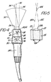
- FIGURE 4 illustrates a modified version of the transducer assembly of FIGURE 1 which is installed in a scan head; and
- FIGURE 5 is a detailed side view of the transducer assembly of FIGURE 4.
- Referring to FIGURE 1, an ultrasonic transducer assembly constructed in accordance with the principles of the present invention is shown. On the
upper face 18 of thetransducer assembly 10 is alinear array 12 of transducer elements. The number of elements inarray 12 may typically nunber 32 or 43. Each element of thearray 12 has a wire connected to the back of it. The wires extend throughbacking material 14, and are connected to a number ofpins 16 at the bottom of the assembly. Thelinear array elements 12 send and received ultrasonic energy for imaging. - Also on the
upper face 10 of thetransducer assembly 10 are twoultrasonic transducers transducers backing material 24 topins 26 at the bottom of the transducer assembly. For continuous wave Doppler operation, one of thetransducers - The
transducers transducers - The
backing materials epoxy backing material 14 is chosen to heavily damp oscillations of thetransducer array 12 so that a quick ring-down time of one or two cycles -is- afforded. The Dopplertransducers epoxy backing material 24 for the Doppler transducers is thus chosen to be less absorbent of ultrasonic energy and thereby provide a longer ring-down time for the Doppler transducers. Thebacking material 24 in the constructed embodiment comprised a softer, more gummy epoxy composition than theheavier backing material 14 for theimaging transducer array 12. - The constructed embodiment of the
transducer assembly 10 of FIGURE 1 was formed by fixing the two transducer types to their respective backing materials in separate operations. The transducer and backing, material sub-assemblies were then glued together along theinterface 30 to form thetransducer assembly 10. - FIGURE 4 shows a transducer assembly of the present invention mounted in a
scan head 84. The transducer assembly is surrounded by a copper shield and is then potted in place in theend piece 82 of the scan head. Theupper face 86 of the scanhead end piece 82 is covered with a polyurethane coating which is acoustically transparent and exhibits a high electrical impedance. Theupper face 86 is lapped smooth and provides a waterproof barrier between the patient and the transducer assembly. - A
cable 80 extends through the scan head.Wires connectors Connectors pins - The center-to-center dimension of the imaging transducer array and Doppler transducer array is of importanc to the user. The
imaging transducer array 12 will produce asector image 90 of the patient's tissue, as shown in FIGURE 4. The center of thesector 90 is aligned with thecenter line 92 of thetransducer array 12. The center line of the Dopplerelements imaging center line 92 as shown by thedashed line 94. It is desirable, however, for the Doppler center line to be substantially coextensive with that of the imaging array so that Doppler measurements can be made in a vessel which is approximately in the center of the image. This is accomplished is the embodiment of FIGURE 4 by canting the Doppler portion of the transducer assembly face so that thecenter line 96 which is normal to the face of the Doppler transducers is substantially coextensive with thecenter line 92 of the imaging array in the center of the image. The faces of the Dopplertransducers imaging transducer array 12, but are tilted at a angle of approximately 3 degrees so that thecenter line 96 from the Doppler transducers will intersect thecenter line 92 of the imaging array at approximately the center of theimage sector 90. - For similar reasons it is desirable to cant the two
Doppler transducers transducer elements center lines 100, 102 from the transducer intersect at apoint 104 which is approximately in the plane of the image sector. The canting of the two Doppler transducer elements provides a measure of mechanical focusing so that the continuous transmission of ultrasonic energy along one of the center line paths 100 or 10: will result in the continuous return of echoes along the other path from apoint 104 which is in the plane of the image. - The desire to tilt the two Doppler transducers toward eac other as shown in FIGURE 5 is obviated in the embodiment of FIGURE 2, in which the Doppler function is performed by a linear array of transducer elements 40. Alternate ones of the transducer elements 40 in FIGURE 2 may be energized for the transmission of Doppler waves, and the remaining interdigitated transducer elements used to con- tinously received returning Doppler waves. Unlike the embodiment of FIGURE 1, the interdigitation of Doppler transmit and receive elements of the embodiment of FIGURE 2 permits the transmit and return paths of Doppler waves to be located in the image plane. The individual elements of the transducer array 40 of FIGURE 2 are connected to a number of
pins 46 at the bottom of the assembly in a similar manner as the connection of the imaging array elements to their respective pins. - A further embodiment of the present invention is shown in FIGURE 3, in which the imaging array of
transducers 12 is interposed between twoDoppler transducers imaging array 12, withedges 54 and 56 being higher than the plane of theimaging array 12. This canting of theDoppler elements center line 60 and 62 of the two Doppler elements is aligned exactly over the center line of the plane of the image ofimaging array 12. The rounded outer edges of theDoppler transducer elements front surface 18. The transducer assembly of FIGURE 3 may then be mounted in a rounded scan head which does not have corners that could cause discomfort when the scan head is pressed against the body of the patient.
Claims (13)
wherein said first and second backing materials are joined at a common interface.
Applications Claiming Priority (2)
| Application Number | Priority Date | Filing Date | Title |
|---|---|---|---|
| US06/476,671 US4492120A (en) | 1983-03-18 | 1983-03-18 | Dual function ultrasonic transducer assembly |
| US476671 | 1983-03-18 |
Publications (2)
| Publication Number | Publication Date |
|---|---|
| EP0120657A1 true EP0120657A1 (en) | 1984-10-03 |
| EP0120657B1 EP0120657B1 (en) | 1990-05-23 |
Family
ID=23892785
Family Applications (1)
| Application Number | Title | Priority Date | Filing Date |
|---|---|---|---|
| EP84301796A Expired - Lifetime EP0120657B1 (en) | 1983-03-18 | 1984-03-16 | Dual function ultrasonic transducer assembly |
Country Status (4)
| Country | Link |
|---|---|
| US (1) | US4492120A (en) |
| EP (1) | EP0120657B1 (en) |
| JP (1) | JPS59230543A (en) |
| DE (1) | DE3482346D1 (en) |
Cited By (1)
| Publication number | Priority date | Publication date | Assignee | Title |
|---|---|---|---|---|
| EP0295302A1 (en) * | 1986-02-28 | 1988-12-21 | Yokogawa Medical Systems, Ltd | Ultrasonic diagnostic device |
Families Citing this family (15)
| Publication number | Priority date | Publication date | Assignee | Title |
|---|---|---|---|---|
| JPS59163957U (en) * | 1983-04-18 | 1984-11-02 | 横河メディカルシステム株式会社 | Ultrasonic dual array probe |
| JPS60122548A (en) * | 1983-12-05 | 1985-07-01 | 株式会社東芝 | Ultrasonic diagnostic apparatus |
| US4802458A (en) * | 1984-03-09 | 1989-02-07 | Ethicon, Inc. | Dual function ultrasonic transducer probes |
| US4598589A (en) * | 1984-07-17 | 1986-07-08 | General Electric Company | Method of CW doppler imaging using variably focused ultrasonic transducer array |
| US4601292A (en) * | 1984-11-08 | 1986-07-22 | Johnson & Johnson Ultrasound, Inc. | Steerable Doppler transducer probes |
| US5070734A (en) * | 1988-06-15 | 1991-12-10 | Matsushita Electric Industrial Co., Ltd. | Ultrasonic diagnostic apparatus |
| US5119821A (en) * | 1990-02-01 | 1992-06-09 | Tuchler Robert E | Diverging signal tandem doppler probe |
| US5217858A (en) * | 1991-09-20 | 1993-06-08 | Eastman Kodak Company | Ultrathin high chloride tabular grain emulsions |
| US5559388A (en) * | 1995-03-03 | 1996-09-24 | General Electric Company | High density interconnect for an ultrasonic phased array and method for making |
| US5558092A (en) * | 1995-06-06 | 1996-09-24 | Imarx Pharmaceutical Corp. | Methods and apparatus for performing diagnostic and therapeutic ultrasound simultaneously |
| US5749831A (en) * | 1997-06-23 | 1998-05-12 | Baker; Donald A. | Fetal cardiac monitoring utilizing umbilical blood flow parameters and heartbeat information |
| US6537224B2 (en) | 2001-06-08 | 2003-03-25 | Vermon | Multi-purpose ultrasonic slotted array transducer |
| US20060009948A1 (en) * | 2003-10-04 | 2006-01-12 | Dannis Wulf | Method and apparatus for inspecting parts with high frequency linear array |
| US10610659B2 (en) | 2017-03-23 | 2020-04-07 | General Electric Company | Gas mixer incorporating sensors for measuring flow and concentration |
| US10946160B2 (en) * | 2017-03-23 | 2021-03-16 | General Electric Company | Medical vaporizer with carrier gas characterization, measurement, and/or compensation |
Citations (3)
| Publication number | Priority date | Publication date | Assignee | Title |
|---|---|---|---|---|
| US3881164A (en) * | 1973-09-13 | 1975-04-29 | Commw Of Australia | Cross array ultrasonic transducer |
| DE3014878A1 (en) * | 1980-04-17 | 1981-10-22 | Siemens AG, 1000 Berlin und 8000 München | Ultra sound test instrument - has several transducers switched for selected frequencies |
| WO1983003000A1 (en) * | 1982-02-18 | 1983-09-01 | Univ Leland Stanford Junior | Ultrasonic transducers and applications thereof |
Family Cites Families (5)
| Publication number | Priority date | Publication date | Assignee | Title |
|---|---|---|---|---|
| US3898840A (en) * | 1974-01-30 | 1975-08-12 | Automation Ind Inc | Multi-frequency ultrasonic search unit |
| US4097835A (en) * | 1976-09-20 | 1978-06-27 | Sri International | Dual transducer arrangement for ultrasonic imaging system |
| US4141347A (en) * | 1976-09-21 | 1979-02-27 | Sri International | Real-time ultrasonic B-scan imaging and Doppler profile display system and method |
| JPS5618770A (en) * | 1979-07-25 | 1981-02-21 | Toshiba Corp | Ultrasonic probe |
| US4257278A (en) * | 1979-08-24 | 1981-03-24 | General Electric Company | Quantitative volume blood flow measurement by an ultrasound imaging system featuring a Doppler modality |
-
1983
- 1983-03-18 US US06/476,671 patent/US4492120A/en not_active Expired - Lifetime
-
1984
- 1984-03-16 DE DE8484301796T patent/DE3482346D1/en not_active Expired - Lifetime
- 1984-03-16 JP JP59050796A patent/JPS59230543A/en active Granted
- 1984-03-16 EP EP84301796A patent/EP0120657B1/en not_active Expired - Lifetime
Patent Citations (3)
| Publication number | Priority date | Publication date | Assignee | Title |
|---|---|---|---|---|
| US3881164A (en) * | 1973-09-13 | 1975-04-29 | Commw Of Australia | Cross array ultrasonic transducer |
| DE3014878A1 (en) * | 1980-04-17 | 1981-10-22 | Siemens AG, 1000 Berlin und 8000 München | Ultra sound test instrument - has several transducers switched for selected frequencies |
| WO1983003000A1 (en) * | 1982-02-18 | 1983-09-01 | Univ Leland Stanford Junior | Ultrasonic transducers and applications thereof |
Cited By (2)
| Publication number | Priority date | Publication date | Assignee | Title |
|---|---|---|---|---|
| EP0295302A1 (en) * | 1986-02-28 | 1988-12-21 | Yokogawa Medical Systems, Ltd | Ultrasonic diagnostic device |
| EP0295302A4 (en) * | 1986-02-28 | 1989-02-16 | Yokogawa Medical Syst | Ultrasonic diagnostic device. |
Also Published As
| Publication number | Publication date |
|---|---|
| US4492120A (en) | 1985-01-08 |
| DE3482346D1 (en) | 1990-06-28 |
| EP0120657B1 (en) | 1990-05-23 |
| JPS59230543A (en) | 1984-12-25 |
| JPH0467456B2 (en) | 1992-10-28 |
Similar Documents
| Publication | Publication Date | Title |
|---|---|---|
| US4492120A (en) | Dual function ultrasonic transducer assembly | |
| EP0458146B1 (en) | Ultrasonic transducer with reduced acoustic cross coupling | |
| US5957851A (en) | Extended bandwidth ultrasonic transducer | |
| US6457365B1 (en) | Method and apparatus for ultrasonic imaging | |
| US5957850A (en) | Multi-array pencil-sized ultrasound transducer and method of imaging and manufacture | |
| US4992692A (en) | Annular array sensors | |
| KR102241694B1 (en) | Ultrasound transducer and ultrasound imaging system with a variable thickness dematching layer | |
| US20030055337A1 (en) | Dual-frequency ultrasonic array transducer and method of harmonic imaging | |
| KR101031010B1 (en) | Pcb and probe therewith | |
| EP0206432A1 (en) | Phased array for ultrasonic medical imaging | |
| US9808830B2 (en) | Ultrasound transducer and ultrasound imaging system with a variable thickness dematching layer | |
| WO2017089376A1 (en) | Ultrasound systems with microbeamformers for different transducer arrays | |
| CN109700479A (en) | A kind of two-dimensional array ultrasound imaging probe | |
| JP5038808B2 (en) | Ultrasonic transducer and ultrasonic probe with ultrasonic transducer | |
| CN105640590B (en) | Ultrasonic probe and method of manufacturing ultrasonic probe | |
| US9833219B2 (en) | Angle oriented array for medical ultrasound | |
| EP0637470A2 (en) | Backing layer for acoustic transducer array | |
| EP3028772B1 (en) | Ultrasonic probe and method of manufacturing the same | |
| JP3358907B2 (en) | Array type ultrasonic probe | |
| JPH11347032A (en) | Ultrasonic probe | |
| EP0709059A2 (en) | Apparatus for coupling acoustic waves with an acoustic waveguide | |
| JP2964147B2 (en) | Ultrasound diagnostic equipment | |
| US20160317125A1 (en) | Ultrasonic device unit, probe, electronic apparatus, and ultrasonic diagnostic apparatus | |
| CN111558514B (en) | Ultrasonic transducer | |
| JPS60137200A (en) | Ultrasonic probe |
Legal Events
| Date | Code | Title | Description |
|---|---|---|---|
| PUAI | Public reference made under article 153(3) epc to a published international application that has entered the european phase |
Free format text: ORIGINAL CODE: 0009012 |
|
| AK | Designated contracting states |
Designated state(s): DE FR GB |
|
| 17P | Request for examination filed |
Effective date: 19850307 |
|
| 17Q | First examination report despatched |
Effective date: 19860516 |
|
| D17Q | First examination report despatched (deleted) | ||
| RAP1 | Party data changed (applicant data changed or rights of an application transferred) |
Owner name: JOHNSON & JOHNSON ULTRASOUND INC. |
|
| GRAA | (expected) grant |
Free format text: ORIGINAL CODE: 0009210 |
|
| AK | Designated contracting states |
Kind code of ref document: B1 Designated state(s): DE FR GB |
|
| REF | Corresponds to: |
Ref document number: 3482346 Country of ref document: DE Date of ref document: 19900628 |
|
| ET | Fr: translation filed | ||
| PLBE | No opposition filed within time limit |
Free format text: ORIGINAL CODE: 0009261 |
|
| STAA | Information on the status of an ep patent application or granted ep patent |
Free format text: STATUS: NO OPPOSITION FILED WITHIN TIME LIMIT |
|
| 26N | No opposition filed | ||
| PGFP | Annual fee paid to national office [announced via postgrant information from national office to epo] |
Ref country code: DE Payment date: 19970321 Year of fee payment: 14 |
|
| PGFP | Annual fee paid to national office [announced via postgrant information from national office to epo] |
Ref country code: GB Payment date: 19980309 Year of fee payment: 15 |
|
| PGFP | Annual fee paid to national office [announced via postgrant information from national office to epo] |
Ref country code: FR Payment date: 19980310 Year of fee payment: 15 |
|
| PG25 | Lapsed in a contracting state [announced via postgrant information from national office to epo] |
Ref country code: DE Free format text: LAPSE BECAUSE OF NON-PAYMENT OF DUE FEES Effective date: 19981201 |
|
| PG25 | Lapsed in a contracting state [announced via postgrant information from national office to epo] |
Ref country code: GB Free format text: LAPSE BECAUSE OF NON-PAYMENT OF DUE FEES Effective date: 19990316 |
|
| GBPC | Gb: european patent ceased through non-payment of renewal fee |
Effective date: 19990316 |
|
| PG25 | Lapsed in a contracting state [announced via postgrant information from national office to epo] |
Ref country code: FR Free format text: LAPSE BECAUSE OF NON-PAYMENT OF DUE FEES Effective date: 19991130 |
|
| REG | Reference to a national code |
Ref country code: FR Ref legal event code: ST |