EP0120344A2 - System for transmitting, recording and/or reproducing a television signal - Google Patents
System for transmitting, recording and/or reproducing a television signal Download PDFInfo
- Publication number
- EP0120344A2 EP0120344A2 EP84102274A EP84102274A EP0120344A2 EP 0120344 A2 EP0120344 A2 EP 0120344A2 EP 84102274 A EP84102274 A EP 84102274A EP 84102274 A EP84102274 A EP 84102274A EP 0120344 A2 EP0120344 A2 EP 0120344A2
- Authority
- EP
- European Patent Office
- Prior art keywords
- signal
- pulses
- time
- transmitted
- pulse
- Prior art date
- Legal status (The legal status is an assumption and is not a legal conclusion. Google has not performed a legal analysis and makes no representation as to the accuracy of the status listed.)
- Granted
Links
Images
Classifications
-
- H—ELECTRICITY
- H04—ELECTRIC COMMUNICATION TECHNIQUE
- H04N—PICTORIAL COMMUNICATION, e.g. TELEVISION
- H04N5/00—Details of television systems
- H04N5/76—Television signal recording
- H04N5/91—Television signal processing therefor
- H04N5/92—Transformation of the television signal for recording, e.g. modulation, frequency changing; Inverse transformation for playback
-
- H—ELECTRICITY
- H04—ELECTRIC COMMUNICATION TECHNIQUE
- H04N—PICTORIAL COMMUNICATION, e.g. TELEVISION
- H04N9/00—Details of colour television systems
- H04N9/79—Processing of colour television signals in connection with recording
- H04N9/80—Transformation of the television signal for recording, e.g. modulation, frequency changing; Inverse transformation for playback
- H04N9/82—Transformation of the television signal for recording, e.g. modulation, frequency changing; Inverse transformation for playback the individual colour picture signal components being recorded simultaneously only
- H04N9/8205—Transformation of the television signal for recording, e.g. modulation, frequency changing; Inverse transformation for playback the individual colour picture signal components being recorded simultaneously only involving the multiplexing of an additional signal and the colour video signal
- H04N9/8211—Transformation of the television signal for recording, e.g. modulation, frequency changing; Inverse transformation for playback the individual colour picture signal components being recorded simultaneously only involving the multiplexing of an additional signal and the colour video signal the additional signal being a sound signal
- H04N9/8222—Transformation of the television signal for recording, e.g. modulation, frequency changing; Inverse transformation for playback the individual colour picture signal components being recorded simultaneously only involving the multiplexing of an additional signal and the colour video signal the additional signal being a sound signal using frequency division multiplex
-
- H—ELECTRICITY
- H04—ELECTRIC COMMUNICATION TECHNIQUE
- H04N—PICTORIAL COMMUNICATION, e.g. TELEVISION
- H04N5/00—Details of television systems
- H04N5/76—Television signal recording
- H04N5/91—Television signal processing therefor
- H04N5/92—Transformation of the television signal for recording, e.g. modulation, frequency changing; Inverse transformation for playback
- H04N5/928—Transformation of the television signal for recording, e.g. modulation, frequency changing; Inverse transformation for playback the sound signal being pulse code modulated and recorded in time division multiplex with the modulated video signal
-
- H—ELECTRICITY
- H04—ELECTRIC COMMUNICATION TECHNIQUE
- H04N—PICTORIAL COMMUNICATION, e.g. TELEVISION
- H04N5/00—Details of television systems
- H04N5/76—Television signal recording
- H04N5/91—Television signal processing therefor
- H04N5/93—Regeneration of the television signal or of selected parts thereof
- H04N5/932—Regeneration of analogue synchronisation signals
-
- H—ELECTRICITY
- H04—ELECTRIC COMMUNICATION TECHNIQUE
- H04N—PICTORIAL COMMUNICATION, e.g. TELEVISION
- H04N9/00—Details of colour television systems
- H04N9/79—Processing of colour television signals in connection with recording
- H04N9/80—Transformation of the television signal for recording, e.g. modulation, frequency changing; Inverse transformation for playback
- H04N9/81—Transformation of the television signal for recording, e.g. modulation, frequency changing; Inverse transformation for playback the individual colour picture signal components being recorded sequentially only
-
- H—ELECTRICITY
- H04—ELECTRIC COMMUNICATION TECHNIQUE
- H04N—PICTORIAL COMMUNICATION, e.g. TELEVISION
- H04N9/00—Details of colour television systems
- H04N9/79—Processing of colour television signals in connection with recording
- H04N9/80—Transformation of the television signal for recording, e.g. modulation, frequency changing; Inverse transformation for playback
- H04N9/82—Transformation of the television signal for recording, e.g. modulation, frequency changing; Inverse transformation for playback the individual colour picture signal components being recorded simultaneously only
- H04N9/8205—Transformation of the television signal for recording, e.g. modulation, frequency changing; Inverse transformation for playback the individual colour picture signal components being recorded simultaneously only involving the multiplexing of an additional signal and the colour video signal
Definitions
- the luminance signal is recorded on the oblique tracks of a magnetic tape by frequency modulation of an image carrier.
- the color carrier which is reduced in frequency to approximately 0.63 MHz, is recorded.
- the invention has for its object to provide better utilization of the available transmission bandwidth, in particular in the sense that the quality of the signal transmission is improved and / or additional signals can be transmitted.
- the inventions are based on the following consideration.
- the color channel of today's video recorders has various deficiencies in terms of signal-to-noise ratio and color fidelity due to the low color carrier frequency of around 630 kHz, the low bandwidth and the necessary reduction in amplitude.
- the PAL or NTSC color carrier In contrast to a frequency or pulse modulated signal, the PAL or NTSC color carrier must be transmitted with the correct amplitude. It is therefore much more advantageous if the color information is also transmitted via the FM channel of the image carrier.
- the frequency carrier which is reduced in frequency, can eg for recording in front of the FM modulator can be added to the luminance signal.
- comb filters are required to separate the luminance signal and the color carrier during playback, which can only be carried out cheaply with half-line offset, that is to say with NTSC.
- Another disadvantage of the comb filter is that the vertical resolution of the luminance signal is reduced.
- Removing the S-pulses not only increases the frequency swing for the BA signal, but also creates the times for the transmission of the time-compressed color signal.
- a value of 1: 5 is appropriate for the compression of the color signal.
- the luminance signal then does not need to be compressed (favorable for luminance bandwidth and effort; see also FKTG lecture No. 9, 1980 about Timeplex).
- the standard blanking times are just sufficient for the 1: 5 compressed signal including a time reserve for the level over passages between the signal areas. In the vertical blanking time, the S-pulses transferred to the BA area can be transmitted.
- the sampling frequency for the compressed signal range can e.g. are around 9 MHz.
- the duration of a raster period is approximately 110 ns.
- the rise time of a pulse edge is approx. 160 ns. This already shows that the pulses transmitted in the V-blanking interval alone are not sufficient to achieve a perfect and reliable timeplex reproduction.
- These devices can also be used for the safe generation of the clock frequencies and the S-pulses required for the expansion of the color signal.
- V blanking time shows the signal in the range of the V blanking time, which is supplied to the FM modulator during recording or is supplied from the FM demodulator during playback.
- VTR video tape recorder
- the time of the head switch is just before the start of the V-blanking time.
- the pulses in the V blanking time provide information about the temporal position of the signals of the following track.
- the clock generated from the PCM signal ensures that this time assignment is maintained until the next head change.
- the H pulses outside the V blanking time can therefore be dispensed with.
- the time-compressed color difference signals are transmitted within the H blanking times.
- the lower amplitude value of the pulses in the V time indicates the black level, the upper amplitude value the zero level for the color difference signals.
- Fig. 2 shows the block diagram of a recording circuit.
- a receiver circuit supplies the CVBS and the audio signal.
- the video recording circuit generates the video signal shown in Fig. 1 and supplies it to the FM modulator.
- the temporal compression of the color difference signals is carried out with the aid of clocked memories.
- the PCM coder delivers, for example, a DM or biphase signal that contains the sound information.
- the spectrum of the PCM signal is limited with a pulse filter so that the video information is not disturbed.
- the FM signal and PCM signal are then fed together to the recording heads.
- the PCM signal occupies approximately the frequency range in which the color carrier signal is transmitted in today's VTR devices. In contrast to the color carrier signal, the PCM signal does not need to be transmitted with exact amplitude. It only depends on the position of the level transitions.
- Fig. 3 shows the block diagram of a playback circuit.
- the FM signal and PCM signal are separated using a crossover.
- the FM demodulator supplies a signal as shown in FIG. 1 to the video playback circuit.
- a PLL circuit generates n times the bit frequency from the PCM transmission signal. This oscillation follows the time fluctuations of the sampled signal. It is used for PCM decoding as well as for signal processing in video advertising and to restore the S-pulses that are not transmitted.
- the basic phase is set by the pulses transmitted in the V-blanking time. These impulses serve Phase setting of counter circuits, which then supply the S-pulses and the clock frequencies for the color signal expansion until the next head change.
- the individual reproducing device can then be supplied with the individual signal components separately or as a composite signal.
- the time compression of the color signals takes place by sampling the color signals and reading in the analog or digitally coded samples in a memory. During the H blanking time, the samples are read out of the memory again at 5 times the frequency. In the case of time expansion, this process is reversed by sampling at five times the frequency, buffering and reading out at the original sampling frequency.
- the PCM bit rate here is 73.75 times the line frequency.
- the Timeplex sampling frequency is 8 times or 8/5 the bit rate.
- the PCM sampling frequency deviates 0.3% 0 from 32 kHz. This deviation is so small that, for example, the video frequency or the PCM frequency can be set to the standard value during playback.
- V-Auszetzeit 25 H periods is thus available in order to classify the timeplex clock and S-pulse generation period-precisely in the time grid given by the 8-fold bit rate (9.22 MHz).
- positive pulses R are transmitted in some blank lines. Such an impulse says e.g. that the leading edge of the subsequent S pulse coincides with the beginning of a bit period of the PCM signal. Because of the factor 73.75 between bit clock and line frequency, this is only the case for every 4th H pulse.
- the R pulse should be present at least once in each V blanking interval. However, it can also be transmitted up to 4 times in the 17 available blank lines.
- Point 1 of this list is superfluous if the factor between the bit clock and the line frequency is an integer.
- the R pulse is only transmitted in even or odd-numbered blank lines, provided that it is supposed to fulfill the task according to point 2 at the same time. Otherwise, the R pulse can be transmitted in any blank lines.
- Fig. 5 shows an example of the counting rule in the Timeplex coding.
- a different counting rule can also be cheaper. If e.g. If a cheap playback circuit is important, the compressed signal will be transmitted as early as possible in order to save the delay compensation for the luminance signal.
- the compression or expansion is carried out with 97 samples 0 ... 96. If clocked analog memories (bucket chain, CCD) are used, they should have 97 levels. 4 or 10 clock periods are available for the transitions between the signal areas.
- the signal shown in FIG. 5 consists of an S pulse and the R pulse formed therefrom by expansion and inversion. Both pulses can also be generated with the aid of counter circuits, especially if the S pulses are regenerated with counter circuits in the case of the Timeplex coding anyway.
- a horizontal frequency time mark (H i , H 2 ) can be generated from the bit clock f B obtained in the PCM decoder and the pulses S and R transmitted in the vertical blanking interval.
- This time stamp is required both for the restoration of the S-pulses during the frame run-up time and for the setting of the counting circuits for timeplex decoding.
- the PCM decoder 49 corresponds e.g. the version described in P 32 48 168, Fig. 9.
- the PCM decoder alternately receives the PCM signal from the two video heads K1 and K2, the bit clock according to which
- Fig. 5 specified numerical example is coupled to the video signal.
- f T1 and f T2 are the bit clocks assigned to the signals of the two heads.
- the respectively current bit clock f B is fed to the video signal processing circuit via a switch 50.
- the output voltage of the VCO (8.f B ) is required for video signal processing. Since the bit clock f B in the example given here shifts from line period to line period by 1/4 f B period compared to the H period, a signal f B 'must first be generated which always has the same phase with respect to the H period of the video signal.
- the signal f B is fed to an 8-bit shift register 51 clocked with 8.f B. At the outputs 2, 4, 6, 8 of this shift register there is then f B with four phases evenly distributed over an f B period. With the help of the selection circuit 52 one of the signals (f B ') is tapped. The selection circuit is switched on with the aid of a 2-bit counter 53, which is clocked at f H. The switching phase of the 2-bit counter can be checked with the help of pulse R.
- the counter can also be set to the value 434 by an external pulse S 'and thus synchronized.
- the pulse S ' is generated with the aid of the two D flip-flops 54, 55 and the gate 56. It also has the duration of a counting period.
- the S-edge of the video signal therefore only causes a rough adjustment by selecting the correct f B 'period.
- the "phase fine adjustment" of the pulse S ' is carried out by f B ', ie by the clock phase of the PCM signal.
- a negative pulse is emitted by gate 59 as soon as a pulse S 'generated from S coincides with the output pulse H 1 of the counter 57. As soon as this negative impulse occurs, the S pulse is expediently no longer fed to the D input of flip-flop 54. The feed takes place again after the next head change.
- H 1 can be used as a time stamp for the video signal processing in the reproduction circuit.
- exact compliance with the signal propagation times will be particularly difficult. It is therefore advisable to use the circuit parts 60 ... 63 to generate a time stamp H 2 , the position of which is monitored and, if necessary, automatically corrected.
- This is made possible by the pulse R transmitted in the vertical blanking interval.
- This pulse R represents a luminance signal for the timeplex decoder, since it is transmitted in the time domain of the luminance signal.
- the associated synchronous pulse transmitted in the time domain of the chrominance signal represents the associated chrominance signal.
- the signal components R L and those resulting from S can be generated
- Signal components R C are tapped from the luminance or chroma signal and compared for the purpose of correcting the time mark H 2 .
- R L and R C are fed to a comparator 63 which is gated in the time domain of R L and R C.
- a count pulse is sent to a up / down counter 62 given.
- the counting direction of the counter is set so that the deviation between R L and R C is counteracted.
- This correction is carried out by a corresponding shift in the time mark H 2 , which is decisive for the start of the counting circuits in the timeplex playback circuit.
- the time stamp can be tapped from the outputs of an 8-bit shift register 60 with 8 phases evenly distributed over an f B period. The tap takes place via the selection circuit 62, which is set by the up / down counter 62.
- the counter 53 need not be brought into a defined switching phase by the R pulse. Since the sequence of the f H pulses which are supplied to the counter 53 is complete, a phase of f B 1 with respect to the H period which has been set once is retained. The time stamp H 1 is then no longer precisely defined, but the position of the time stamp H 2 used is automatically optimally set by the circuit parts 60 ... 63.
- the transmission and evaluation of the pulses R and S is of course also advantageous if no clock signal coupled to the time plex signal is available.
- the timeplex signal must contain a horizontal frequency signal which, after separation, produces the timeplex sampling frequencies 8.f B and 8/5.
- f B and the time stamp H 1 or H 2 is used.
- the time stamp H 2 can be set automatically by comparing the signals R L and R C.
Abstract
Description
Bei Videorecordern nach den Systemen VHS, Betamax und V 2000 wird das Leuchtdichtesignal durch Frequenzmodulation eines Bildträgers auf Schrägspuren eines Magnetbandes aufgezeichnet. Unterhalb des Frequenzbereiches des modulierten Bildträgers wird der in der Frequenz auf etwa 0,63 MHz herabgesetzte Farbträger aufgezeichnet. Zur Verbesserung der Tonqualität ist es auch bekannt (DE-OS 31 16 130), mit den Videoköpfen ein oder mehrere mit Tonsignalen frequenzmodulierte Tonträger aufzuzeichnen. Da die gesamte verfügbare Aufzeichnungsbandbreite von 6 MHz durch den Farbträger und den Bildträger voll eingenommen ist, muß für derartige Tonträger ein zusätzlicher Frequenzbereich geschaffen werden. Dazu ist es bekannt, im Frequenzbereich des modulierten Bildträgers Frequenzbereiche für den Tonträger zu unterdrücken oder das obere Seitenband des Farbträgers oder das untere Seitenband des Bildträgers einzuengen.In the case of video recorders based on the VHS, Betamax and V 2000 systems, the luminance signal is recorded on the oblique tracks of a magnetic tape by frequency modulation of an image carrier. Below the frequency range of the modulated image carrier, the color carrier, which is reduced in frequency to approximately 0.63 MHz, is recorded. To improve the sound quality, it is also known (DE-OS 31 16 130) to use the video heads to record one or more sound carriers frequency-modulated with sound signals. Since the entire available recording bandwidth of 6 MHz is fully occupied by the color carrier and the image carrier, an additional frequency range must be created for such sound carriers. For this purpose, it is known to suppress frequency ranges for the sound carrier in the frequency range of the modulated image carrier or to narrow the upper side band of the color carrier or the lower side band of the image carrier.
Die gleichen Überlegungen gelten, wenn es sich nicht um einen Videorecorder, sondern um eine Übertragungsstrecke für ein Fernsehsignal handelt, z.B. bei einer Kabelübertragung, einem Fernsehtelefon oder einer Satellitenübertragung.The same considerations apply if it is not a video recorder but a transmission link for a television signal, e.g. with a cable transmission, a television telephone or a satellite transmission.
Ein Verfahren für die Übertragung kontinuierlicher PCM-Signale bei VTR-Geräten, das sind Video-Tape-Recorder, ist in der älteren Patentanmeldung P 32 48 168 beschrieben.A method for the transmission of continuous PCM signals in VTR devices, that is video tape recorders, is described in the earlier patent application P 32 48 168.
Versuche haben gezeigt, daß bei Videorecordern nach der VHS-Norm anstelle des modulierten Farbträgers ein PCM-Stereosignal mit 14 Bit Quantisierung und 32 kHz-Abtastrate je Kanal übertragen werden kann, ohne daß eine unzulässige Störung des Videosignals erfolgt. Die Fehlerrate des PCM-Signales ist dabei außerordentlich gering. Diese Möglichkeit einer hochwertigen Tonübertragung kann nur ausgenutzt werden, wenn auf die Übertragung der Farbinformation verzichtet wird oder wenn es gelingt, durch bessere Ausnutzung der verfügbaren Übertragungskapazität einen neuen Farbkanal zu schaffen.Experiments have shown that in the case of video recorders according to the VHS standard, instead of the modulated color carrier, a PCM stereo signal with 14-bit quantization and 32 kHz sampling rate per channel can be transmitted without causing an impermissible disturbance in the video signal. The error rate of the PCM signal is extremely low. This possibility of high-quality sound transmission can only be used if the transmission of the color information is dispensed with or if it is possible to create a new color channel by making better use of the available transmission capacity.
Der Erfindung liegt die Aufgabe zugrunde, eine bessere Ausnutzung der verfügbaren Übertragungsbandbreite zu schaffen, insbesondere in dem Sinne, daß die Qualität der Signalübertragung verbessert wird und/oder zusätzliche Signale übertragen werden können.The invention has for its object to provide better utilization of the available transmission bandwidth, in particular in the sense that the quality of the signal transmission is improved and / or additional signals can be transmitted.
Diese Aufgabe wird durch die im Anspruch 1 und 10 beschriebenen Erfindungen gelöst. Vorteilhafte Weiterbildungen der Erfindungen sind in den jeweiligen Unteransprüchen beschrieben.This object is achieved by the inventions described in
Die Erfindungen beruhen auf folgender Überlegung. Der Farbkanal der heutigen Videorecorder hat wegen der geringen Farbträgerfrequenz von etwa 630 kHz,der geringen Bandbreite und der notwendigen Amplitudenabsenkung verschiedene Mängel hinsichtlich Störabstand und Farbtreue. Der PAL- oder NTSC-Farbträger muß im Gegensatz zu einem frequenz- oder pulsmodulierten Signal amplitudenrichtig übertragen werden. Es ist daher wesentlich vorteilhafter, wenn die Farbinformation auch über den FM-Kanal des Bildträgers übertragen wird. Der in der Frequenz herabgesetzte Farbträger kann z.B. für die Aufzeichnung vor dem FM-Modulator zum Leuchtdichtesignal addiert werden. Dann sind jedoch zur Trennung von Leuchtdichtesignal und Farbträger bei der Wiedergabe Kammfilter erforderlich, die nur beim Halbzeilenoffset, also bei NTSC, günstig ausführbar sind. Ein weiterer Nachteilderartiger Kammfilter besteht darin, daß die Vertikalauflösung des Leuchtdichtesignals verringert wird.The inventions are based on the following consideration. The color channel of today's video recorders has various deficiencies in terms of signal-to-noise ratio and color fidelity due to the low color carrier frequency of around 630 kHz, the low bandwidth and the necessary reduction in amplitude. In contrast to a frequency or pulse modulated signal, the PAL or NTSC color carrier must be transmitted with the correct amplitude. It is therefore much more advantageous if the color information is also transmitted via the FM channel of the image carrier. The frequency carrier, which is reduced in frequency, can eg for recording in front of the FM modulator can be added to the luminance signal. Then, however, comb filters are required to separate the luminance signal and the color carrier during playback, which can only be carried out cheaply with half-line offset, that is to say with NTSC. Another disadvantage of the comb filter is that the vertical resolution of the luminance signal is reduced.
Eine weitere Möglichkeit, die Farbinformation mit über den FM-Kanal zu übertragen, ist durch das bekannte Timeplex-oder Lineplexverfahren gegeben, wie es im Vortrag Nr. 9 der Fernseh- und Kinotechnischen Gesellschaft in Berlin am 07.10.1980 der Öffentlichkeit vorgestellt wurde. Bei diesem Verfahren werden in den Horizontalaustastzeiten außer den zeitkomprimierten Farbsignalen noch schmale S-Impulse und Bezugspegelbereiche übertragen. Auf diese Impulse kann verzichtet werden, wenn eine Taktfrequenz zur Verfügung steht, die den gleichen Zeitschwankungen unterworfen ist wie das Videosignal. Der aus dem PCM-Signal regenerierte Bit-Takt ist dafür geeignet. Die Bezugspegel für Schwarz und Unbunt können in der Vertikalaustastzeit übertragen werden.Another way of transmitting the color information via the FM channel is through the well-known timeplex or lineplex method, as was presented to the public on October 7, 1980 in lecture No. 9 of the Television and Kinotechnical Society in Berlin. With this method, narrow S-pulses and reference level ranges are transmitted in the horizontal blanking times in addition to the time-compressed color signals. These pulses can be dispensed with if a clock frequency is available which is subject to the same time fluctuations as the video signal. The bit clock regenerated from the PCM signal is suitable for this. The reference levels for black and achromatic can be transmitted in the vertical blanking time.
Durch das Entfernen der S-Impulse wird nicht nur der Frequenzhub für das BA-Signal vergrößert, sondern es werden auch die Zeiten für die Übertragung des zeitlich komprimierten Farbsignals geschaffen. Für die Kompression des Farbsignals ist ein Wert von 1:5 zweckmäßig. Das Luminanzsignal braucht dann nicht komprimiert zu werden (günstig für Luminanzbandbreite und Aufwand; vgl. hierzu auch FKTG-Vortrag Nr. 9, 1980 über Timeplex). Die normgemäßen Austastzeiten sind gerade ausreichend für das 1:5 komprimierte Signal einschließlich einer Zeitreserve für die Pegelübergänge zwischen den Signalbereichen. In der Vertikalaustastzeit können die in den BA-Bereich verlegten S-Impulse übertragen werden.Removing the S-pulses not only increases the frequency swing for the BA signal, but also creates the times for the transmission of the time-compressed color signal. A value of 1: 5 is appropriate for the compression of the color signal. The luminance signal then does not need to be compressed (favorable for luminance bandwidth and effort; see also FKTG lecture No. 9, 1980 about Timeplex). The standard blanking times are just sufficient for the 1: 5 compressed signal including a time reserve for the level over passages between the signal areas. In the vertical blanking time, the S-pulses transferred to the BA area can be transmitted.
Die Abtastfrequenz für den komprimierten Signalbereich kann z.B. bei ca. 9 MHz liegen. Damit die zeitliche Expansion exakt durchgeführt werden kann, ist es wichtig, daß sich die Wiedergabeschaltung nach jedem Kopfwechsel in dieses 9 MHz-Zeitraster wieder periodengenau hineinschaltet. Die Dauer einer Rasterperiode beträgt ca. 110 ns. Bei einer Signalbandbreite von 3 MHz beträgt aber die Anstiegszeit einer Impulsflanke ca. 160 ns. Das zeigt schon, daß die in der V-Austastlücke übertragenen Impulse allein nicht ausreichend sind, um eine einwandfreie und sichere Timeplex-Wiedergabe zu realisieren.The sampling frequency for the compressed signal range can e.g. are around 9 MHz. In order that the temporal expansion can be carried out exactly, it is important that the playback circuit switches back into the 9 MHz time grid after every head change. The duration of a raster period is approximately 110 ns. With a signal bandwidth of 3 MHz, the rise time of a pulse edge is approx. 160 ns. This already shows that the pulses transmitted in the V-blanking interval alone are not sufficient to achieve a perfect and reliable timeplex reproduction.
Auch für die Wiederherstellung der S-Impulse wäre es nicht tragbar, wenn die Impulslage von Teilbild zu Teilbild um 110 ns springen könnte.It would also be unsustainable for the restoration of the S-pulses if the pulse position could jump by 110 ns from field to field.
In P 32 48 168 wurde erklärt, weshalb jeder Kopfwechsel einen unbestimmten Phasensprung für das Signal bedeutet.In P 32 48 168 it was explained why every head change means an indefinite phase change for the signal.
Es wurde dort auch gezeigt, wie innerhalb der Überlappungszeit mit Sicherheit die richtige Phasenzuordnung zwischen dem Signal der neuen Spur und einer noch von der alten Spur geregelten PLL-Schwingung hergestellt werden kann.It was also shown there how the correct phase assignment between the signal of the new track and a PLL oscillation still controlled by the old track can be established with certainty within the overlap time.
Diese Einrichtungen können auch für die sichere Erzeugung der für die Expansion des Farbsignals erforderlichen Taktfrequenzen und der S-Impulse ausgenutzt werden.These devices can also be used for the safe generation of the clock frequencies and the S-pulses required for the expansion of the color signal.
Die Erfindung wird im folgenden anhand der Zeichnung er- __ läutert. Darin zeigen
- Fig. 1 das Signal während der Vertikalaustastzeit,
- Fig. 2 das Blockschaltbild einer Aufnahmeschaltung,
- Fig. 3 das Blockschaltbild einer entsprechenden Wiedergabeschaltung,
- Fig. 4 Ausschnitte aus der Vertikalaustastzeit,
- Fig. 5 ein Zahlenbeispiel für Fig. 4,
- Fig. 6 eine Schaltung für die Erzeugung von Zeilensynchronimpulsen (H., H2),
- Fig. 7 ein Impulsdiagramm zur Erläuterung der Wirkungsweise von Fig. 6.
- 1 shows the signal during the vertical blanking time,
- 2 shows the block diagram of a recording circuit,
- 3 shows the block diagram of a corresponding playback circuit,
- 4 excerpts from the vertical blanking time,
- 5 shows a numerical example for FIG. 4,
- F i g. 6 shows a circuit for generating line synchronizing pulses (H., H 2),
- FIG. 7 shows a pulse diagram to explain the mode of operation of FIG. 6.
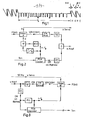
Fig. 1 zeigt das Signal im Bereich der V-Austastzeit, das bei der Aufzeichnung dem FM-Modulator zugeführt wird bzw. bei der Wiedergabe vom FM-Demodulator geliefert wird. Bei der Wiedergabe vom VTR (VTR = Video-Tape-Recorder) liegt der Zeitpunkt der Kopfumschaltung kurz vor Beginn der V-Austastzeit. Die Impulse in der V-Austastzeit geben Auskunft über die zeitliche Lage der Signale der folgenden Spur. Daß diese zeitliche Zuordnung bis zum nächsten Kopfwechsel beibehalten wird, dafür sorgt der aus dem PCM-Signal erzeugte Takt.1 shows the signal in the range of the V blanking time, which is supplied to the FM modulator during recording or is supplied from the FM demodulator during playback. When playing back from the VTR (VTR = video tape recorder), the time of the head switch is just before the start of the V-blanking time. The pulses in the V blanking time provide information about the temporal position of the signals of the following track. The clock generated from the PCM signal ensures that this time assignment is maintained until the next head change.
Auf die H-Impulse außerhalb der V-Austastzeit kann also verzichtet werden. Innerhalb der H-Austastzeiten werden dafür die zeitlich komprimierten Farbdifferenzsignale übertragen. Der untere Amplitudenwert der Impulse in der V-Zeit gibt den Schwarzpegel an, der obere Amplitudenwert den Nullpegel für die Farbdifferenzsignale.The H pulses outside the V blanking time can therefore be dispensed with. The time-compressed color difference signals are transmitted within the H blanking times. The lower amplitude value of the pulses in the V time indicates the black level, the upper amplitude value the zero level for the color difference signals.
Fig. 2 zeigt das Blockschaltbild einer Aufnahmeschaltung. Eine Empfängerschaltung liefert das FBAS- und das Tonsignal. Die Video-Aufnahmeschaltung erzeugt das in Fig. 1 dargestellte Videosignal und liefert es an den FM-Modulator. Die zeitliche Kompression der Farbdifferenzsignale wird mit Hilfe getakteter Speicher durchgeführt. Die Impulsabtrennung erzeugt das V-Signal für die Servoschaltung der Aufzeichnungsmaschine und das H-Signal für eine PLL, die die N-fache H-Frequenz erzeugt. Dies ist gleichzeitig der n-fache Bittakt. Wenn z.B. N ungerade und n = 4 ist, dann liegen die Pegelübergänge des PCM-Signals in einem Viertelzeilen-Offset. Der PCM-Coder liefert z.B. ein DM- oder Biphase-Signal, das die Toninformation enthält. Das Spektrum des PCM-Signals wird mit einem Impulsfilter so begrenzt, daß die Video-Information nicht gestört wird. FM-Sigual und PCM-Signal werden dann zusammen den Aufzeichnungsköpfen zugeführt. Das PCM-Signal nimmt etwa den Frequenzbereich ein, in dem bei den heutigen VTR-Geräten das Farbträgersignal übertragen wird. Im Gegensatz zum Farbträgersignal braucht das PCM-Signal nicht amplitudengenau übertragen zu werden. Es kommt hier nur auf die Lage der Pegelübergänge an.Fig. 2 shows the block diagram of a recording circuit. A receiver circuit supplies the CVBS and the audio signal. The video recording circuit generates the video signal shown in Fig. 1 and supplies it to the FM modulator. The temporal compression of the color difference signals is carried out with the aid of clocked memories. The pulse separation generates the V signal for the servo circuit of the recording machine and the H signal for a PLL which generates the N times the H frequency. This is also the n-fold bit clock. For example, if N is odd and n = 4, the level transitions of the PCM signal are in a quarter line offset. The PCM coder delivers, for example, a DM or biphase signal that contains the sound information. The spectrum of the PCM signal is limited with a pulse filter so that the video information is not disturbed. The FM signal and PCM signal are then fed together to the recording heads. The PCM signal occupies approximately the frequency range in which the color carrier signal is transmitted in today's VTR devices. In contrast to the color carrier signal, the PCM signal does not need to be transmitted with exact amplitude. It only depends on the position of the level transitions.
Fig. 3 zeigt das Blockschaltbild einer Wiedergabeschaltung. Mit Hilfe einer Frequenzweiche werden FM-Signal und PCM-Signal getrennt. Der FM-Demodulator liefert ein Signal gemäß Fig. 1 an die Video-Wiedergabeschaltung.Fig. 3 shows the block diagram of a playback circuit. The FM signal and PCM signal are separated using a crossover. The FM demodulator supplies a signal as shown in FIG. 1 to the video playback circuit.
Eine PLL-Schaltung erzeugt aus dem PCM-Übertragungssignal die n-fache Bitfrequenz. Diese Schwingung folgt den Zeitschwankungen des abgetasteten Signals. Sie dient sowohl zur PCM-Decodierung als auch zur Signalverarbeitung in der Video-Wiergabescheltung und zur Wiederherstellung der nicht mitübertragenen S-Impulse. Dabei erfolgt die Einstellung der Grundphase jeweils durch die in der V-Austastzeit übertragenen Impulse. Diese Impulse dienen zur Phaseneinstellung von Zählschaltungen, die dann bis zum nächsten Kopfwechsel die S-Impulse und die Taktfrequenzen für die Farbsignal-Expansion liefern. Der e%pntlichen Wiedergabeeinrichtung können dann die einzelnen Signalkomponenten getrennt oder als FBAS-Signal zugeführt werden.A PLL circuit generates n times the bit frequency from the PCM transmission signal. This oscillation follows the time fluctuations of the sampled signal. It is used for PCM decoding as well as for signal processing in video advertising and to restore the S-pulses that are not transmitted. The basic phase is set by the pulses transmitted in the V-blanking time. These impulses serve Phase setting of counter circuits, which then supply the S-pulses and the clock frequencies for the color signal expansion until the next head change. The individual reproducing device can then be supplied with the individual signal components separately or as a composite signal.
Ein geeignetes Verfahren für PCM-Übertragung bei VTR-Geräten ist in der älteren Patentanmeldung P 32 48 168 beschrieben.A suitable method for PCM transmission in VTR devices is described in the earlier patent application P 32 48 168.
Die Zeitkompression der Farbsignale erfolgt durch Abtasten der Farbsignale und Einlesen der analogen oder digital codierten Abtastwerte in einem Speicher. Während der H-Austastzeit werden die Abtastwerte mit 5-facher Frequenz wieder aus dem Speicher ausgelesen. Bei der Zeitexpansion wird dieser Vorgang durch Abtasten mit fünffacher Frequenz, Zwischenspeichern und Auslesen mit der ursprünglichen Abtastfrequenz wieder rückgängig gemacht.The time compression of the color signals takes place by sampling the color signals and reading in the analog or digitally coded samples in a memory. During the H blanking time, the samples are read out of the memory again at 5 times the frequency. In the case of time expansion, this process is reversed by sampling at five times the frequency, buffering and reading out at the original sampling frequency.
Für Fig. 5 gilt das folgende Zahlenbeispiel:

Es soll nun das Ausführungsbeispiel erläutert werden: Die PCM-Bitrate ist hier das 73,75-fache der Zeilenfrequenz. Die Timeplex-Abtastfrequenz ist das 8-fache bzw. 8/5 der Bitrate.The exemplary embodiment will now be explained: The PCM bit rate here is 73.75 times the line frequency. The Timeplex sampling frequency is 8 times or 8/5 the bit rate.
Die PCM-Abtastfrequenz weicht um 0,3%0 von 32 kHz ab. Diese Abweichung ist so gering, daß z.B. bei der Wiedergabe wahlweise die Videofrequenz oder die PCM-Frequenz auf den Normwert gelegt werden kann.The PCM sampling frequency deviates 0.3% 0 from 32 kHz. This deviation is so small that, for example, the video frequency or the PCM frequency can be set to the standard value during playback.
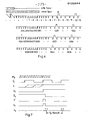
In Fig. 4 sind Ausschnitte der V-Austastzeit von 4 aufeinanderfolgenden Teilbildern dargestellt. Die Überlappungszeit der abgetasteten Signale endet etwa zu Beginn der V-Austastzeit (s. Fig. 4 oben). Zu diesem Zeitpunkt ist also auf jeden Fall die Phasenanpassung des PCM-Signals der neuen Spur an die PLL-Schwingung vollzogen (vgl. ältere Patentanmeldung P 32 48 168). Die gesamte V-Austzetzeit (25 H-Perioden) steht also zur Verfügung, um die Timeplextakt- und die S-Impuls-Erzeugung periodengenau in das durch die 8-fache Bitrate (9,22 MHz) gegebene Zeitraster einzuordnen.4 shows sections of the V-blanking time of 4 successive fields. The overlap time of the sampled signals ends approximately at the beginning of the V blanking time (see FIG. 4 above). At this point in time, the phase adjustment of the PCM signal of the new track to the PLL oscillation has been completed in any case (cf. older patent application P 32 48 168). The entire V-Auszetzeit (25 H periods) is thus available in order to classify the timeplex clock and S-pulse generation period-precisely in the time grid given by the 8-fold bit rate (9.22 MHz).
Wie aus Fig. 4 ersichtlich, werden in einigen Leerzeilen positive Impulse R übertragen. Ein derartiger Impuls sagt z.B. aus, daß die Vorderflanke des nadfolgenden S-Impulses mit dem Beginn einer Bitperiode des PCM-Signals übereinstimmt. Wegen des Faktors 73,75 zwischen Bittakt und Zeilenfrequenz ist dies nur bei jedem 4. H-Impuls der Fall. Der R-Impuls soll in jeder V-Austastlücke mindestens einmal vorhanden -sein. Er kann aber auch in den 17 verfügbaren Leerzeilen bis zu 4 mal übertragen werden.As can be seen from FIG. 4, positive pulses R are transmitted in some blank lines. Such an impulse says e.g. that the leading edge of the subsequent S pulse coincides with the beginning of a bit period of the PCM signal. Because of the factor 73.75 between bit clock and line frequency, this is only the case for every 4th H pulse. The R pulse should be present at least once in each V blanking interval. However, it can also be transmitted up to 4 times in the 17 available blank lines.
Dieser R-Impuls übt hier mehrere Funktionen aus:
- 1. Er überwacht in der Takterzeugungsschaltung die Zählphase eines bis-4-Zählers für die Zeilenfrequenz. Falls die Zählphase nicht korrekt ist, erfolgt Rückstellung durch den R-Impuls und damit Richtigstellung der Zählphase.
- 2. Der Impuls kennzeichnet die Phase der R-Y, B-Y-Sequenz.
- 3. Der Impuls stellt den vorschriftsmäßig expandierten invertierten S-Impuls dar (s. Fig. 5). Der Impuls bietet dann die Möglichkeit, die richtige Einstellung der Timeplex-Wiedergabeschaltung zu kontrollieren. Bei einer Normung der Zählvorschriften für die Aufnahme muß die einmal richtig eingestellte Timeplex-Wiedergabeschaltung für alle denkbaren Abspielungen von vornherein korrekt arbeiten. Es wäre aber auch denkbar, daß unterschiedliche Aufnahmeschaltungen mit unterschiedlichen Zählphasen arbeiten. In der Wiedergabeschaltung müßte dann die Zählphase der jeweiligen Aufnahme automatisch angepaßt werden. Das könnte dadurch geschehen, daß der für die Timeplex-Takterzeugung maßgebliche Impuls in der Wiedergabeschaltung von den Abgriffen eines Schieberegisters abgenommen wird, das mit der Frequenz 8.fB getaktet ist. Aufgrund eines Vergleichs des expandierten S-Impulses mit dem R-Impuls kann z.B. die Wahl des Schieberegisterabgriffes automatisch erfolgen. Damit ist in jedem Fall die korrekte Einstellung des Timeplex-Decoders sichergestellt.
- 1. It monitors the counting phase of a to-4 counter for the line frequency in the clock generation circuit. If the counting phase is not correct, it is reset by the R pulse and thus the counting phase is corrected.
- 2nd The pulse identifies the phase of the RY, BY sequence.
- 3. The pulse represents the correctly expanded inverted S pulse (see FIG. 5). The pulse then offers the possibility of checking the correct setting of the timeplex playback circuit. When standardizing the counting rules for recording, the correctly set timeplex playback circuit must work correctly from the outset for all conceivable plays. But it would also be conceivable that different recording circuits work with different counting phases. The counting phase of the respective recording would then have to be automatically adjusted in the playback circuit. This could be done in that the pulse in the playback circuit which is decisive for the timeplex clock generation is taken from the taps of a shift register which is clocked at the frequency 8.f B. Based on a comparison of the expanded S pulse with the R pulse, the selection of the shift register tap can be made automatically. This ensures that the Timeplex decoder is set correctly.
Punkt 1 dieser Aufzählung erübrigt sich, wenncer Faktor zwischen Bittakt und Zeilenfrequenz ganzzahlig ist. In diesem Fall wird dann der R-Impuls nur in geradzahligen bzw. ungeradzahligen Leerzeilen übertragen, sofern er gleichzeitig die Aufgabe gemäß Punkt 2 erfüllen soll. Anderenfalls kann der R-Impuls in beliebigen Leerzeilen übertragen werden.
Fig. 5 zeigt ein Beispiel für die Zählvorschrift bei der Timeplex-Codierung. Je nach Schaltungskonzept kann auch eine andere Zählvorschrift günstiger sein. Wenn es z.B. auf eine billige Wiedergabeschaltung ankommt, wird man das komprimierte Signal möglichst früh übertragen, um damit den Laufzeitausgleich für das Luminanzsignal einzusparen. Im Beispiel 'Fig. 5 wird die Kompression bzw. Expansion mit 97 Abtastwerten 0 ... 96 durchgeführt. Bei Verwendung getakteter Analogspeicher (Eimerkette, CCD) müßten diese 97 Stufen besitzen. Für die Übergänge zwischen den Signalbereichen stehen 4 bzw. 10 Taktperioden zur Verfügung.Fig. 5 shows an example of the counting rule in the Timeplex coding. Depending on the circuit concept, a different counting rule can also be cheaper. If e.g. If a cheap playback circuit is important, the compressed signal will be transmitted as early as possible in order to save the delay compensation for the luminance signal. In the example 'Fig. 5, the compression or expansion is carried out with 97
Das in Fig. 5 dargestellte Signal besteht aus einem S-Impuls und dem daraus durch Expansion und Invertierung gebildeten R-Impuls. Beide Impulse können auch mit Hilfe von Zählschaltungen erzeugt werden, besonders dann, wenn die S-Impulse sowieso mit Zählschaltungen bei der Timeplex-Codierung regeneriert werden.The signal shown in FIG. 5 consists of an S pulse and the R pulse formed therefrom by expansion and inversion. Both pulses can also be generated with the aid of counter circuits, especially if the S pulses are regenerated with counter circuits in the case of the Timeplex coding anyway.
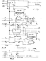
Anhand von Fig. 6 und 7 wird nun erläutert, wie aus dem im PCM-Decoder gewonnenen Bittakt fB und den in der VertikalAustastlücke übertragenen Impulsen S und R eine horizontalfrequente Zeitmarke (Hi,H2) erzeugt werden kann. Diese Zeitmarke ist sowohl für die Wiederherstellung der S-Impulse während der Bildhinlaufzeit als auch für die Einstellung der Zählschaltungen zur Timeplex-Decodierung erforderlich.6 and 7, it will now be explained how a horizontal frequency time mark (H i , H 2 ) can be generated from the bit clock f B obtained in the PCM decoder and the pulses S and R transmitted in the vertical blanking interval. This time stamp is required both for the restoration of the S-pulses during the frame run-up time and for the setting of the counting circuits for timeplex decoding.
Der PCM-Decoder 49 entspricht z.B. der in P 32 48 168, Fig. 9 beschriebenen Ausführung.The
Der PCM-Decoder erhält von den beiden Videoköpfen K1 und K2 abwechselnd das PCM-Signal, dessen Bittakt gemäß dem zuThe PCM decoder alternately receives the PCM signal from the two video heads K1 and K2, the bit clock according to which
Fig. 5 angegebenen Zahlenbeispiel mit dem Videosignal verkoppelt ist. Der VCO in der PLL-Schaltung für die Regenerierung des Bittaktes schwingt hier mit der 8-fachen Bitrate. fT1 und fT2 sind die den Signalen der beiden Köpfe zugeordneten Bittakte. Über einen Umschalter 50 wird der jeweils aktuelle Bittakt fB der Videosignalverarbeitungsschaltung zugeführt. Außerdem wird die Ausgangsspannung des VCO (8.fB) für die Videosignalverarbeitung benötigt. Da der Bittakt fB in dem hier angegebenen Beispiel sich von Zeilenperiode zu Zeilenperiode um jeweils 1/4 fB-Periode gegenüber der H-Periode verschiebt, muß zuerst ein Signal fB' erzeugt werden, das stets die gleiche Phase in Bezug auf die H-Periode des Videosignals hat. Zu diesem Zweck wird hier das Signal fB einem mit 8.fB getakteten 8-Bit-Schieberegister 51 zugeführt. An den Ausgängen 2,4,6,8 dieses Schieberegisters steht dann fB mit vier gleichmäßig über eine fB-Periode verteilten Phasen zur Verfügung. Mit Hilfe der Auswahlschaltung 52 wird jeweils eins der Signale (fB') abgegriffen. Die Auswahlschaltung wird mit Hilfe eines 2-bit-Zählers 53, der mit fH getaktet ist, weitergeschaltet. Mit Hilfe des Impulses R kann die Schaltphase des 2-bit-Zählers kontrolliert werden.Fig. 5 specified numerical example is coupled to the video signal. The VCO in the PLL circuit for the regeneration of the bit clock oscillates here at 8 times the bit rate. f T1 and f T2 are the bit clocks assigned to the signals of the two heads. The respectively current bit clock f B is fed to the video signal processing circuit via a
Die mit Hilfe der Schaltungsteile 51 bis 53 durchgeführten Maßnahmen erübrigen sich, wenn fB ein ganzzahliges Vielfaches der Zeilenfrequenz ist. Dann ist fB 9 = fB. fB' hat also eine definierte Phase in Bezug auf die H-Periode des Videosignals. Nach jeder Kopfumschaltung, die jeweils kurz vor der Vertikalaustastzeit erfolgt, muß durch die in der Vertikalaustastzeit übertragenen Impulse des Videosignals ein Zähler 57, der zwecks Erzeugung der horizontalfrequenten Zeitmarke H1,H2 die Perioden von 8.fB zählt, periodengenau synchronisiert werden. Die Problematik dieser Aufgabe wird durch Zeile 1 und 3 der Fig. 7 veranschaulicht: Da die Impulse des Videosignals eine Anstiegszeit besitzen, die der Dauer von ein bis zwei Perioden der Frequenz 8.fB entspricht, kann kaum entschieden werden, welche 8.fB-Periode einer Synchronimpulsflanke zuzuordnen ist. Benutzt man dagegen fB' für die nach jeder Kopfumschaltung erforderliche Phaseneinstellung des Zählers 57, dann kann die S-Impulsflanke durch Flankenrauschen oder andere Störungen in dem durch gestrichelte Linien in Fig. 7, Zeile 3 angegebenen Bereich schwanken, ohne daß eine falsche Phaseneinstellung hervorgerufen wird.The measures carried out with the aid of the
Der Zähler 57 ist so aufgebaut, daß er nach jeweils 1023 Zählperioden einen Impuls H1 mit der Dauer einer Zählperiode abgibt. Dieser Impuls bewirkt, daß die 1024. Zählperiode den Zähler auf den Wert 434 voreinstellt. Dadurch zählt der Zähler zwischen zwei H1-Impulsen jeweils 1024 - 434 = 590 Perioden der Frequenz 8.fB (vgl. Zahlenbeispiel Fig. 5).The counter 57 is constructed in such a way that it emits a pulse H 1 with the duration of one counting period after every 1023 counting periods. This pulse causes the 1024th counting period to preset the counter to the value 434. As a result, the counter counts between 1024 and 434 = 590 periods of frequency 8.f B between two H 1 pulses (see numerical example in FIG. 5).
Über das Gatter 58 kann der Zähler auch durch einen externen Impuls S' auf den Wert 434 eingestellt und damit synchronisiert werden. Der Impuls S' wird mit Hilfe der beiden D - Flip-Flops 54,55 und des Gatters 56 erzeugt. Er hat ebenfalls die Dauer einer Zählperiode. Die S-Flanke des Videosignals bewirkt also lediglich eine Grobeinstellung, indem sie die richtige fB'-Periode auswählt. Die "Phasenfeineinstellung" des Impulses S' erfolgt dagegen durch fB', d.h. durch die Taktphase des PCM-Signals.Via the
Von Gatter 59 wird ein negativer Impuls abgegeben, sobald ein aus S erzeugter Impuls S' mit dem Ausgangsimpuls H1 des Zählers 57 zusammenfällt. Sobald dieser negative Impuls auftritt, wird zweckmäßigerweise der S-Impuls dem D-Eingang des Flip-Flops 54 nicht mehr zugeführt. Die Zuführung erfolgt erst wieder nach dem nächsten Kopfwechsel.A negative pulse is emitted by
Sofern alle Zählvorschriften und Signallaufzeiten für die PCM- und Timeplex-Signalverarbeitung sowohl auf der Aufzeichnungs- als auch auf der Wiedergabeseite genau festgelegt sind und eingehalten werden, kann H1 als Zeitmarke für die Videosignalverarbeitung in der Wiedergabeschaltung verwendet werden. Besonders die genaue Einhaltung der Signallaufzeiten wird in der Praxis Schwierigkeiten bereiten. Deshalb empfiehlt es sich, mit Hilfe der Schaltungsteile 60 ... 63 eine Zeitmarke H2 zu erzeugen, deren Lage überwacht und ggf. automatisch korrigiert wird. Dieses wird ermöglicht durch den in der Vertikalaustastlücke übertragenen Impuls R. Dieser Impuls R stellt für den Timeplex-Decoder ein Luminanzsignal dar, da er im Zeitbereich des Luminanzsignals übertragen wird. Der im Zeitbereich des Chrominanzsignals übertragene zuge hörige Synchronimpuls stellt das zugehörige Chrominanzsignal dar. Nach der Timeplexsignalverarbeitung, und zwar genau an der Stelle, wo das Luminanzsignal und das Chrominanzsignal zwecks Bildwiedergabe zusammengesetzt werden, können die aus R entstandenen Signalanteile RL und die aus S entstandenen Signalanteile RC aus dem Luminanz- bzw. Chroma-Signal abgegriffen und zwecks Korrektur der Zeitmarke H2 verglichen werden.Provided that all counting rules and signal propagation times for the PCM and Timeplex signal processing on both the recording and the reproduction side are precisely defined and adhered to, H 1 can be used as a time stamp for the video signal processing in the reproduction circuit. In practice, exact compliance with the signal propagation times will be particularly difficult. It is therefore advisable to use the
In Fig. 6 werden RL und RC einem Vergleicher 63 zugeführt, der im Zeitbereich von RL und RC aufgetastet wird. Sobald die zeitliche Abweichung zwischen beiden Signalen einen vorgegebenen Wert (z.B. Dauer einer 8.fB-Periode) überschreitet, wird ein Zählimpuls auf einen Vor/Rück-Zähler 62 gegeben. Gleichzeitig wird die Zählrichtung des Zählers so eingestellt, daß der Abweichung zwischen RL und RC entgegengewirkt wird. Diese Korrektur erfolgt durch eine entsprechende Verschiebung der Zeitmarke H2, die für den Start der Zählschaltungen in der Timeplexwiedergabeschaltung maßgeblich ist. Die Zeitmarke ist hierzu von den Ausgängen eines 8-bit-Schieberegisters 60 mit 8 gleichmäßig über eine fB-Periode verteilten Phasen abgreifbar. Der Abgriff erfolgt über die Auswahlschaltung 62, die durch den Vor/ Rück-Zähler 62 eingestellt wird.In Fig. 6, R L and R C are fed to a
Bei Verwendung der soeben beschriebenen Schaltungsvariante braucht der Zähler 53 nicht durch den R-Impuls in eine definierte Schaltphase gebracht zu werden. Da die Folge der fH-Impulse, die dem Zähler 53 zugeführt werden, vollständig ist, bleibt eine einmal eingestellte Phase von fB 1 in Bezug auf die H-Periode erhalten. Die Zeitmarke H1 ist dann zwar nicht mehr genau definiert, jedoch wird die Lage der verwendeten Zeitmarke H2 automatisch durch die Schaltungsteile 60 ... 63 optimal eingestellt.When using the circuit variant just described, the
Die Übertragung und aie Auswertung der Impulse R und S ist natürlich auch dann vorteilhaft, wenn kein mit dem Timeplexsignal verkoppeltes Taktsignal zur Verfügung steht. In diesem Fall muß das Timeplexsignal ein horizontalfrequentes Signal enthalten, das nach Abtrennung zur Erzeugung der Timeplex-Abtastfrequenzen 8.fB und 8/5 . fB und der Zeitmarke H1 bzw. H2 verwendet wird. Auch hier kann durch Vergleich der Signale RL und RC die automatische Einstellung der Zeitmarke H2 erfolgen.The transmission and evaluation of the pulses R and S is of course also advantageous if no clock signal coupled to the time plex signal is available. In this case, the timeplex signal must contain a horizontal frequency signal which, after separation, produces the timeplex sampling frequencies 8.f B and 8/5. f B and the time stamp H 1 or H 2 is used. Here, too, the time stamp H 2 can be set automatically by comparing the signals R L and R C.
Claims (12)
Priority Applications (1)
| Application Number | Priority Date | Filing Date | Title |
|---|---|---|---|
| AT84102274T ATE37645T1 (en) | 1983-03-25 | 1984-03-02 | SYSTEM FOR TRANSMISSION, RECORDING AND/OR REPRODUCTION OF A TELEVISION SIGNAL. |
Applications Claiming Priority (2)
| Application Number | Priority Date | Filing Date | Title |
|---|---|---|---|
| DE3310890 | 1983-03-25 | ||
| DE3310890A DE3310890C2 (en) | 1983-03-25 | 1983-03-25 | System for the transmission of a television signal, in particular for recording and reproduction |
Publications (3)
| Publication Number | Publication Date |
|---|---|
| EP0120344A2 true EP0120344A2 (en) | 1984-10-03 |
| EP0120344A3 EP0120344A3 (en) | 1985-12-04 |
| EP0120344B1 EP0120344B1 (en) | 1988-09-28 |
Family
ID=6194630
Family Applications (1)
| Application Number | Title | Priority Date | Filing Date |
|---|---|---|---|
| EP84102274A Expired EP0120344B1 (en) | 1983-03-25 | 1984-03-02 | System for transmitting, recording and/or reproducing a television signal |
Country Status (6)
| Country | Link |
|---|---|
| EP (1) | EP0120344B1 (en) |
| JP (1) | JPS59181883A (en) |
| KR (1) | KR920007918B1 (en) |
| AT (1) | ATE37645T1 (en) |
| DE (2) | DE3310890C2 (en) |
| ES (1) | ES530882A0 (en) |
Cited By (3)
| Publication number | Priority date | Publication date | Assignee | Title |
|---|---|---|---|---|
| EP0215604A2 (en) * | 1985-09-11 | 1987-03-25 | Royal Children's Hospital | Video and analogue data recording system |
| EP0232940A1 (en) * | 1986-02-03 | 1987-08-19 | Koninklijke Philips Electronics N.V. | Method of recording and/or reading a video signal, for example an MAC signal, apparatus for carrying out the method, and magnetic record carrier obtained by means of the method |
| FR2635623A1 (en) * | 1988-08-19 | 1990-02-23 | Philips Nv | SYNCHRONIZATION DEVICE ON DIGITAL DATA PACKETS AND READER COMPRISING SAME |
Families Citing this family (3)
| Publication number | Priority date | Publication date | Assignee | Title |
|---|---|---|---|---|
| DE3323750A1 (en) * | 1983-07-01 | 1985-01-17 | Telefunken Fernseh Und Rundfunk Gmbh, 3000 Hannover | Clamping circuit for a signal without adequate blanking intervals, particularly for a video signal |
| DE3345143A1 (en) * | 1983-12-14 | 1985-06-27 | Telefunken Fernseh Und Rundfunk Gmbh, 3000 Hannover | Device and method for recording and/or transmitting colour television signals |
| DE4114605A1 (en) * | 1991-05-04 | 1992-12-03 | Telefunken Fernseh & Rundfunk | Compatible transmission of television signal mode additional information |
Citations (5)
| Publication number | Priority date | Publication date | Assignee | Title |
|---|---|---|---|---|
| US4015286A (en) * | 1975-01-23 | 1977-03-29 | Eli S. Jacobs | Digital color television system |
| FR2345872A1 (en) * | 1976-03-26 | 1977-10-21 | Fuchs Helga | Video phonic equipment for conference - has camera and microphones with digital converter and switching unit |
| EP0011016A1 (en) * | 1978-10-31 | 1980-05-14 | Thomson-Brandt | Transmitting system for audio-visual television signals synchronised by a pilot frequency, and method for putting it into operation |
| US4233627A (en) * | 1977-08-09 | 1980-11-11 | The General Corporation | Signal multiplexing system |
| WO1981003098A1 (en) * | 1980-04-15 | 1981-10-29 | Harris Video Systems Inc | Sampling and re-formatting method and system for processing color video type signals to improve picture quality |
Family Cites Families (5)
| Publication number | Priority date | Publication date | Assignee | Title |
|---|---|---|---|---|
| DE872218C (en) * | 1944-06-28 | 1953-03-30 | Cfcmug | Device for synchronizing the image scanning movements in television systems |
| US3755624A (en) * | 1968-06-26 | 1973-08-28 | Communications Satellite Corp | Pcm-tv system using a unique word for horizontal time synchronization |
| DE2939230C2 (en) * | 1979-09-27 | 1982-08-12 | Siemens AG, 1000 Berlin und 8000 München | Method of transferring data |
| DE3116130A1 (en) * | 1981-04-23 | 1982-11-11 | Licentia Patent-Verwaltungs-Gmbh, 6000 Frankfurt | Video recorder with improved sound reproduction |
| DE3362122D1 (en) * | 1982-07-30 | 1986-03-27 | Indep Broadcasting Authority | Transmission and/or reception of television pictures |
-
1983
- 1983-03-25 DE DE3310890A patent/DE3310890C2/en not_active Expired
-
1984
- 1984-03-02 AT AT84102274T patent/ATE37645T1/en not_active IP Right Cessation
- 1984-03-02 EP EP84102274A patent/EP0120344B1/en not_active Expired
- 1984-03-02 DE DE8484102274T patent/DE3474395D1/en not_active Expired
- 1984-03-14 JP JP59047313A patent/JPS59181883A/en active Pending
- 1984-03-22 ES ES530882A patent/ES530882A0/en active Granted
- 1984-03-26 KR KR1019840001552A patent/KR920007918B1/en not_active IP Right Cessation
Patent Citations (5)
| Publication number | Priority date | Publication date | Assignee | Title |
|---|---|---|---|---|
| US4015286A (en) * | 1975-01-23 | 1977-03-29 | Eli S. Jacobs | Digital color television system |
| FR2345872A1 (en) * | 1976-03-26 | 1977-10-21 | Fuchs Helga | Video phonic equipment for conference - has camera and microphones with digital converter and switching unit |
| US4233627A (en) * | 1977-08-09 | 1980-11-11 | The General Corporation | Signal multiplexing system |
| EP0011016A1 (en) * | 1978-10-31 | 1980-05-14 | Thomson-Brandt | Transmitting system for audio-visual television signals synchronised by a pilot frequency, and method for putting it into operation |
| WO1981003098A1 (en) * | 1980-04-15 | 1981-10-29 | Harris Video Systems Inc | Sampling and re-formatting method and system for processing color video type signals to improve picture quality |
Non-Patent Citations (4)
| Title |
|---|
| EBU REVIEW - TECHNICAL, no. 200, August 1983, Seiten 172-185, Br}ssel, BE; H. MERTENS u.a.: "The C-MAC/packet system for direct satellite television" * |
| IBA EXPERIMENTAL & DEVELOPMENT REPORT, Nr. 118, August 1982, Seiten 1-39, Independent Broadcasting Authority, Winchester, Hants., GB; M.D. WINDRAM u.a.: "MAC - a television system for high-quality stallite broadcasting" * |
| IEE PROCEEDINGS, Sektion A A I, Band 129, Teil A, Nr. 7, September 1982, Seiten 485-492, Old Woking, Surrey, GB; T.S. ROBSON: "Extended-definition television service" * |
| IEE PROCEEDINGS, Sektion A A I, Band 129, Teil A, Nr. 7, September 1982, Seiten 528-531, Old Woking, Surrey, GB; M.D. WINDRAM: "Multiple sound channels in satellite broadcasting" * |
Cited By (6)
| Publication number | Priority date | Publication date | Assignee | Title |
|---|---|---|---|---|
| EP0215604A2 (en) * | 1985-09-11 | 1987-03-25 | Royal Children's Hospital | Video and analogue data recording system |
| EP0215604A3 (en) * | 1985-09-11 | 1988-10-12 | Royal Children's Hospital | Video and analogue data recording system |
| EP0232940A1 (en) * | 1986-02-03 | 1987-08-19 | Koninklijke Philips Electronics N.V. | Method of recording and/or reading a video signal, for example an MAC signal, apparatus for carrying out the method, and magnetic record carrier obtained by means of the method |
| FR2635623A1 (en) * | 1988-08-19 | 1990-02-23 | Philips Nv | SYNCHRONIZATION DEVICE ON DIGITAL DATA PACKETS AND READER COMPRISING SAME |
| EP0355919A1 (en) * | 1988-08-19 | 1990-02-28 | Koninklijke Philips Electronics N.V. | Device for synchronizing on digital data packets, and playback device comprising the same |
| US5465277A (en) * | 1988-08-19 | 1995-11-07 | U.S. Philips Corporation | Device for the synchronization of digital data bursts and read apparatus comprising the device |
Also Published As
| Publication number | Publication date |
|---|---|
| EP0120344B1 (en) | 1988-09-28 |
| DE3310890A1 (en) | 1984-10-04 |
| EP0120344A3 (en) | 1985-12-04 |
| KR840008256A (en) | 1984-12-13 |
| ES8503192A1 (en) | 1985-02-16 |
| KR920007918B1 (en) | 1992-09-19 |
| DE3474395D1 (en) | 1988-11-03 |
| JPS59181883A (en) | 1984-10-16 |
| DE3310890C2 (en) | 1986-01-30 |
| ES530882A0 (en) | 1985-02-16 |
| ATE37645T1 (en) | 1988-10-15 |
Similar Documents
| Publication | Publication Date | Title |
|---|---|---|
| DE2317490C2 (en) | Process for converting continuous audio signals into audio signals compressed in time and arrangement for carrying out the process | |
| DE2945378C2 (en) | ||
| DE2914022C2 (en) | ||
| DE2906770C2 (en) | ||
| DE3107032A1 (en) | ARRANGEMENT FOR TRANSMITTING A COLOR TV SIGNAL | |
| DE2629706B2 (en) | Method for the transmission and / or recording of color television signals | |
| DE2258028C2 (en) | Circuit arrangement for recording and reproducing a composite color television signal on or from a magnetic recording medium | |
| EP0123959B1 (en) | Videorecorder with videotext signal recording | |
| DE2637642A1 (en) | DEVICE FOR COMPENSATING SIGNAL ERRORS IN A RECORDING / PLAYBACK DEVICE FOR VIDEO SIGNALS | |
| DE3345142C1 (en) | Circuit for time compression or time expansion of a video signal | |
| EP0120344B1 (en) | System for transmitting, recording and/or reproducing a television signal | |
| DE2627465C2 (en) | Circuit arrangement for recording or reproducing television signals comprising video signals and audio signals on / from a recording medium | |
| DE2759867C2 (en) | Arrangement for digitizing an analog information signal in a predetermined phase relationship with a reference signal | |
| DE2058001C3 (en) | Circuit arrangement for converting facsimile, in particular color facsimile, signals into signals suitable for transmission in a television system | |
| DE3409418A1 (en) | COMPENSATION CIRCUIT FOR A VIDEO SIGNAL FAILURE | |
| DE2711922B2 (en) | Device for recoding a composite signal and use in a video record player RCA Corp, New York, N.Y. (VStA.) | |
| DE1437851B2 (en) | DEVICE FOR RECORDING AND REPLAYING BROADBAND SIGNALS IN PARTICULAR VIDIO SIGNALS | |
| DE3314782C2 (en) | ||
| DE3135373C2 (en) | Device for reproducing a color television signal | |
| EP0111157B1 (en) | Transmission method, especially for recording and reproducing television signals | |
| EP0582583A1 (en) | Video recorder for the recording of video signals transmitted by the letterbox process. | |
| EP0141130A1 (en) | Time-sequential television transmission system, especially for a video tape recorder | |
| DE3345143C2 (en) | ||
| EP0193648B1 (en) | Apparatus for recording and reproduction of secam colour video signals | |
| DE4112203C1 (en) |
Legal Events
| Date | Code | Title | Description |
|---|---|---|---|
| PUAI | Public reference made under article 153(3) epc to a published international application that has entered the european phase |
Free format text: ORIGINAL CODE: 0009012 |
|
| AK | Designated contracting states |
Designated state(s): AT BE CH DE FR GB IT LI LU NL SE |
|
| PUAL | Search report despatched |
Free format text: ORIGINAL CODE: 0009013 |
|
| AK | Designated contracting states |
Designated state(s): AT BE CH DE FR GB IT LI LU NL SE |
|
| 17P | Request for examination filed |
Effective date: 19860228 |
|
| 17Q | First examination report despatched |
Effective date: 19870820 |
|
| ITF | It: translation for a ep patent filed |
Owner name: BARZANO' E ZANARDO MILANO S.P.A. |
|
| GRAA | (expected) grant |
Free format text: ORIGINAL CODE: 0009210 |
|
| AK | Designated contracting states |
Kind code of ref document: B1 Designated state(s): AT BE CH DE FR GB IT LI LU NL SE |
|
| REF | Corresponds to: |
Ref document number: 37645 Country of ref document: AT Date of ref document: 19881015 Kind code of ref document: T |
|
| REF | Corresponds to: |
Ref document number: 3474395 Country of ref document: DE Date of ref document: 19881103 |
|
| ET | Fr: translation filed | ||
| GBT | Gb: translation of ep patent filed (gb section 77(6)(a)/1977) | ||
| PLBI | Opposition filed |
Free format text: ORIGINAL CODE: 0009260 |
|
| 26 | Opposition filed |
Opponent name: GRUNDIG E.M.V. ELEKTRO-MECHANISCHE VERSUCHSANSTALT Effective date: 19890627 |
|
| NLR1 | Nl: opposition has been filed with the epo |
Opponent name: GRUNDIG E.M.V. ELEKTRO-MECHANISCHE VERSUCHSANSTALT |
|
| PLBN | Opposition rejected |
Free format text: ORIGINAL CODE: 0009273 |
|
| STAA | Information on the status of an ep patent application or granted ep patent |
Free format text: STATUS: OPPOSITION REJECTED |
|
| 27O | Opposition rejected |
Effective date: 19900831 |
|
| NLR2 | Nl: decision of opposition | ||
| ITTA | It: last paid annual fee | ||
| PGFP | Annual fee paid to national office [announced via postgrant information from national office to epo] |
Ref country code: SE Payment date: 19920302 Year of fee payment: 9 |
|
| PGFP | Annual fee paid to national office [announced via postgrant information from national office to epo] |
Ref country code: AT Payment date: 19920310 Year of fee payment: 9 |
|
| PGFP | Annual fee paid to national office [announced via postgrant information from national office to epo] |
Ref country code: BE Payment date: 19920325 Year of fee payment: 9 |
|
| PGFP | Annual fee paid to national office [announced via postgrant information from national office to epo] |
Ref country code: CH Payment date: 19920331 Year of fee payment: 9 |
|
| PG25 | Lapsed in a contracting state [announced via postgrant information from national office to epo] |
Ref country code: AT Effective date: 19930302 |
|
| PG25 | Lapsed in a contracting state [announced via postgrant information from national office to epo] |
Ref country code: SE Effective date: 19930303 |
|
| PG25 | Lapsed in a contracting state [announced via postgrant information from national office to epo] |
Ref country code: LI Effective date: 19930331 Ref country code: CH Effective date: 19930331 Ref country code: BE Effective date: 19930331 |
|
| PGFP | Annual fee paid to national office [announced via postgrant information from national office to epo] |
Ref country code: NL Payment date: 19930331 Year of fee payment: 10 |
|
| EPTA | Lu: last paid annual fee | ||
| BERE | Be: lapsed |
Owner name: TELEFUNKEN FERNSEH UND RUNDFUNK G.M.B.H. Effective date: 19930331 |
|
| REG | Reference to a national code |
Ref country code: CH Ref legal event code: PL |
|
| PGFP | Annual fee paid to national office [announced via postgrant information from national office to epo] |
Ref country code: LU Payment date: 19940331 Year of fee payment: 11 |
|
| PG25 | Lapsed in a contracting state [announced via postgrant information from national office to epo] |
Ref country code: NL Effective date: 19941001 |
|
| NLV4 | Nl: lapsed or anulled due to non-payment of the annual fee | ||
| EUG | Se: european patent has lapsed |
Ref document number: 84102274.2 Effective date: 19931008 |
|
| PG25 | Lapsed in a contracting state [announced via postgrant information from national office to epo] |
Ref country code: LU Free format text: LAPSE BECAUSE OF NON-PAYMENT OF DUE FEES Effective date: 19950302 |
|
| REG | Reference to a national code |
Ref country code: GB Ref legal event code: 746 Effective date: 19970904 |
|
| PGFP | Annual fee paid to national office [announced via postgrant information from national office to epo] |
Ref country code: GB Payment date: 19980205 Year of fee payment: 15 |
|
| PGFP | Annual fee paid to national office [announced via postgrant information from national office to epo] |
Ref country code: FR Payment date: 19980311 Year of fee payment: 15 |
|
| PGFP | Annual fee paid to national office [announced via postgrant information from national office to epo] |
Ref country code: DE Payment date: 19980320 Year of fee payment: 15 |
|
| PG25 | Lapsed in a contracting state [announced via postgrant information from national office to epo] |
Ref country code: GB Free format text: LAPSE BECAUSE OF NON-PAYMENT OF DUE FEES Effective date: 19990302 |
|
| GBPC | Gb: european patent ceased through non-payment of renewal fee |
Effective date: 19990302 |
|
| PG25 | Lapsed in a contracting state [announced via postgrant information from national office to epo] |
Ref country code: FR Free format text: LAPSE BECAUSE OF NON-PAYMENT OF DUE FEES Effective date: 19991130 |
|
| REG | Reference to a national code |
Ref country code: FR Ref legal event code: ST |
|
| PG25 | Lapsed in a contracting state [announced via postgrant information from national office to epo] |
Ref country code: DE Free format text: LAPSE BECAUSE OF NON-PAYMENT OF DUE FEES Effective date: 20000101 |