EP0116968A1 - Adaptive echo canceller - Google Patents
Adaptive echo canceller Download PDFInfo
- Publication number
- EP0116968A1 EP0116968A1 EP84101659A EP84101659A EP0116968A1 EP 0116968 A1 EP0116968 A1 EP 0116968A1 EP 84101659 A EP84101659 A EP 84101659A EP 84101659 A EP84101659 A EP 84101659A EP 0116968 A1 EP0116968 A1 EP 0116968A1
- Authority
- EP
- European Patent Office
- Prior art keywords
- tap coefficient
- output
- correction signal
- echo
- signals
- Prior art date
- Legal status (The legal status is an assumption and is not a legal conclusion. Google has not performed a legal analysis and makes no representation as to the accuracy of the status listed.)
- Granted
Links
- 230000003044 adaptive effect Effects 0.000 title claims abstract description 20
- 238000012937 correction Methods 0.000 claims abstract description 34
- 238000004891 communication Methods 0.000 claims description 5
- 230000004044 response Effects 0.000 claims 1
- 238000010586 diagram Methods 0.000 description 6
- 238000001228 spectrum Methods 0.000 description 5
- 230000005540 biological transmission Effects 0.000 description 4
- 238000009825 accumulation Methods 0.000 description 1
- 230000002411 adverse Effects 0.000 description 1
- 238000013459 approach Methods 0.000 description 1
- 230000000903 blocking effect Effects 0.000 description 1
- 230000000694 effects Effects 0.000 description 1
- 230000006870 function Effects 0.000 description 1
- 230000006872 improvement Effects 0.000 description 1
- 238000000034 method Methods 0.000 description 1
- 238000012986 modification Methods 0.000 description 1
- 230000004048 modification Effects 0.000 description 1
- 230000008569 process Effects 0.000 description 1
- 238000012360 testing method Methods 0.000 description 1
- 238000012546 transfer Methods 0.000 description 1
Images


Classifications
-
- H—ELECTRICITY
- H04—ELECTRIC COMMUNICATION TECHNIQUE
- H04B—TRANSMISSION
- H04B3/00—Line transmission systems
- H04B3/02—Details
- H04B3/20—Reducing echo effects or singing; Opening or closing transmitting path; Conditioning for transmission in one direction or the other
- H04B3/23—Reducing echo effects or singing; Opening or closing transmitting path; Conditioning for transmission in one direction or the other using a replica of transmitted signal in the time domain, e.g. echo cancellers
- H04B3/238—Reducing echo effects or singing; Opening or closing transmitting path; Conditioning for transmission in one direction or the other using a replica of transmitted signal in the time domain, e.g. echo cancellers using initial training sequence
Definitions
- This invention relates to an adaptive echo canceller for cancelling echo signals which inherently occur in long distance 2-wire communications networks, and more specifically to such a canceller which prevents tap coefficients of a transversal filter from drifting toward excessively large values or from divergence.
- An adaptive echo canceller actually estimates the echo and then subtracts it out, and hence is capable of much better performance due to the absence of the opening and closing of the transmission line.
- An adaptive echo canceller includes an echo estimator in the form of a transversal filter.
- the characteristics of the echo estimator are determined using incoming signals.
- the stable operations of the adaptive echo canceller requires that the incoming signals have a frequency bandwidth or spectrum equal to or wider than that of the actual echo path. More specifically, the echo cancellation is limited to the frequency bandwidth of the incoming signals. No problem therefore exists where the incoming signals are signals having a wide frequency band such as voice signals or white noises in that the incoming signal is capable of covering the actual echo path in terms of frequency bandwidth.
- the object of this invention is therefore to provide an adaptive echo canceller which is simple in a circuit arrangement and is capable of effectively cancelling echo signals irrespective of the frequency bandwidth of the incoming signals.
- an adaptive echo canceller in order to prevent tap coefficient values from divergence, viz., drifting toward excessively large values, is provided with a correction signal controller which (a) reduces the tap coefficient values upon the polarities of the tap coefficient signal and the tap coefficient correction signal coinciding and (b) increases the tap coefficient values upon the polarities differing.
- the present invention takes a form of an adaptive echo canceller for cancelling echo signals in communication paths, comprising: an echo estimator for adaptively producing estimated echo signals using incoming signals, the estimated echo path being a type of transversal filter including a tap coefficient memory; a subtracter adapted to subtract the estimated echo signals from echo signals; a tap coefficient correction signal generator for producing tap coefficient correction signals according to the output of the subtracer and the incoming signals; a tap coefficient updating adder for receiving the output of the tap coefficient correction signal generator and a corresponding_tap coefficient signal stored in the tap coefficient memory for updating the tap coefficient signal; and a tap coefficient signal controller for controlling the output of the tap coefficient correction signal generator according to the outputs of the tap coefficient correction signal generator and the tap coefficent memory.
- the adaptive echo canceller 100 generally comprises an input terminal 102 to which incoming signals are applied over a first transmission line 103, an output terminal 104 coupled to one terminal of a 4-wire to 2-wire hybrid circuit 90, an input terminal 106 coupled to the other terminal of the hybrid circuit 90, an output terminal 108 coupled to a second transmission line 109, a digital transversal filter 110, a subtracter 112, a correction signal generator (or arithmetic circuit) 114, a correction signal controller 116, and an adder 118, all of which are connected as shown.
- the digital transversal filter 110 includes a register 200 for storing the incoming signals, a convolution integrator 202 and a tap coefficient memory 204. While, the correction signal generator 114 includes two multipliers 206 and 208, a divider 210 and a square-and-add circuit 212.
- the incoming signals are applied, via the input terminal 102, on the one hand to the register 200, and on the other hand to the hybrid circuit 90 through the output terminal 104.
- the convolution integrator 202 receives the output of the register 200 and also updated tap coefficient signals over a line 203, and thence produces an estimated echo signal on a line 205.
- the subtracter 112 is supplied with communication signals along with echo from the hybrid circuit 90, and also receives the estimated echo signals from the transversal filter 110, and thence subtracts out the echo.
- the output signal ej of the subtracter 112 is fed to the output terminal 108 and also to the multiplier 206 of the correction signal generator 114.
- the correction signal generator 114 receives the signal e and performs an arithmetic operation according to the following equation (1), and thence produces a tap coefficient correction signal dh. (j): wherein:
- the correction signal controller 116 receives the output dh i (j) of the generator 114 and an i-th tap coefficient signal h i (j) from the memory 204, and thence applies a controlled correction signal dh i (j) ' to the adder 118.
- the adder 118 is supplied with the signal dh i (j)' as well as the i-th tap coefficient signal h i (j), sums same and applies a corrected or updated tap coefficient signal hi(j+1) to the convolution integrator 110.
- the operation of the adder 118 is represented by the following equation (2):
- the present invention features the provision of the correction signal controller 116 which prevents the tap coefficient values from drifing towards excessively large values due to accumulation of error signals.
- the correction signal controller 116 will be discussed in more detail with reference to Figs. 2 and 3.
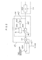
- Fig. 2 is a block diagram showing a first embodiment of the correction signal controller 116 according to the present invention together with some blocks relevant thereto.
- the controller 116 comprises an exclusive OR gate 300, a constant value selector 302 and a multiplier 304.
- the exclusive OR gate 300 is supplied with the i-th tap coefficient correction signal dh i (j) and the i-th tap coefficient signal h i (j), and produces a.logic 0 (for example) if the polarities of the two received signals are identical and otherwise produces a logic 1.
- the selector 302 is responsive to the output of the exclusive OR gate 300 selecting one constant value Kl'when receiving logic 0 and the other constant value K 2 when receiving logic 1 (Kl ⁇ K2).
- the selected constant value Kl or K2 is applied to the multiplier 304, which is arranged to multiply the received value (Kl or K2) with the tap coefficient correction signal dh i (j) from the generator 114 and thence applies the resultant tap coefficient signal dh.(J)' to the adder 118.
- the signal dh i (j) is applied to the adder 18 in the form of the controlled signal dh i (j)' after being reduced in value at the multiplier 304.
- the signal dh i (j) is supplied as the controlled signal dh i (j) after being increased in its value.
- the controller 116 comprises an exclusive OR gate 400, two multipliers 402 and 404, and a selector 406.
- the exclusive OR gate 400 is supplied with the i-th tap coefficient correction signal dh i (j) and the i-th tap coefficient signal h i (j), and produces a logic 0 (for example) if the polarities of the two received signals are identical and otherwise produces a logic 1. While, the correction signal dh i (j) is applied to both multipliers 402 and 404, which respectively multiply the signal dh i (j) with the constant values Kl and K2 (Kl ⁇ K2) and apply the resultant outputs to the selector 406.
- the selector 406 responds to the output of the exclusive OR gate 400 selecting the output of the multiplier 402 upon reception of the logic 0 and the other constant value K2 upon reception of the logic 1.
- one of the outputs of the multipliers 402 and 404 is selectively applied to the adder 118. In this way, the arrangement of Fig. 3 features the same desired effects as discussed with reference to Fig. 2.
Landscapes
- Engineering & Computer Science (AREA)
- Computer Networks & Wireless Communication (AREA)
- Signal Processing (AREA)
- Cable Transmission Systems, Equalization Of Radio And Reduction Of Echo (AREA)
- Filters That Use Time-Delay Elements (AREA)
Abstract
Description
- This invention relates to an adaptive echo canceller for cancelling echo signals which inherently occur in long distance 2-wire communications networks, and more specifically to such a canceller which prevents tap coefficients of a transversal filter from drifting toward excessively large values or from divergence.
- 2-wire communications networks have been constantly plagued by "echo". A known approach to solving this problem is the use of echo suppressors. An echo suppressor opens a send-path to block echo when it detects signal on a receive-path. However, the decision to open is overruled if the return signal from a 4-wire to 2-wire hybrid circuit is deduced to contain near-end party's signal irrespective of the presence of echo to permit the near-end party's signal to be transmitted to the far end. The echo suppressor is thus inherently incapable of blocking echo when both parties are trying to talk simultaneously, i.e., during so-called double talk. Another problem encountered with this type of arrangement is that it imparts a chopping to speech by the opening and closing of the transmission path. Both of these shortcomings have been found more annoying particularly with the echo encountered with satellite circuits (for example).
- In order to overcome these problems, adaptive echo cancellers have been proposed. An adaptive echo canceller actually estimates the echo and then subtracts it out, and hence is capable of much better performance due to the absence of the opening and closing of the transmission line.
- An adaptive echo canceller includes an echo estimator in the form of a transversal filter. The characteristics of the echo estimator are determined using incoming signals. The stable operations of the adaptive echo canceller requires that the incoming signals have a frequency bandwidth or spectrum equal to or wider than that of the actual echo path. More specifically, the echo cancellation is limited to the frequency bandwidth of the incoming signals. No problem therefore exists where the incoming signals are signals having a wide frequency band such as voice signals or white noises in that the incoming signal is capable of covering the actual echo path in terms of frequency bandwidth.
- However, there are some cases where signals having relatively a narrow frequency band, such as test tone signals or MODEM (Modulator-Demodulator) signals, are successively applied to an adaptive echo canceller. In such a case, the adaptive echo canceller fails to estimate echo with respect to the frequency spectrum not involved in the incoming signals. When the estimation is disturbed by external noises entering the echo signals, arithmetic errors are generated. These errors do not adversely affect the estimtion process of the echo signals if the frequency spectrum of the incoming signals is equal to or extends over the frequency spectrum of the actual echo path.
- However, in the case where the incoming signals have a narrow frequency bandwidth, it is no longer expected to exactly estimate a transfer function for identifying the characteristics of the echo estimator. If such identification continues for a long period, arithmetic errors are accumulated to result in the possibility of the dynamic range of a tap coefficient memory being exceeded. Under these divergence conditions, it is impossible to cancel the echo signal.
- In order to overcome these problems, Donald L. Duttweiler disclosed in U.S. patent No. 4,243,959 an echo canceller entiled "Adaptive Filter With Tap Coefficient Leakage". However, the adaptive filter of this prior art is complex in a circuit arrangement.
- The object of this invention is therefore to provide an adaptive echo canceller which is simple in a circuit arrangement and is capable of effectively cancelling echo signals irrespective of the frequency bandwidth of the incoming signals.
- Briefly, this object is fulfilled by an arrangement wherein, in order to prevent tap coefficient values from divergence, viz., drifting toward excessively large values, an adaptive echo canceller is provided with a correction signal controller which (a) reduces the tap coefficient values upon the polarities of the tap coefficient signal and the tap coefficient correction signal coinciding and (b) increases the tap coefficient values upon the polarities differing.
- More specifically, the present invention takes a form of an adaptive echo canceller for cancelling echo signals in communication paths, comprising: an echo estimator for adaptively producing estimated echo signals using incoming signals, the estimated echo path being a type of transversal filter including a tap coefficient memory; a subtracter adapted to subtract the estimated echo signals from echo signals; a tap coefficient correction signal generator for producing tap coefficient correction signals according to the output of the subtracer and the incoming signals; a tap coefficient updating adder for receiving the output of the tap coefficient correction signal generator and a corresponding_tap coefficient signal stored in the tap coefficient memory for updating the tap coefficient signal; and a tap coefficient signal controller for controlling the output of the tap coefficient correction signal generator according to the outputs of the tap coefficient correction signal generator and the tap coefficent memory.
- The features and advantages of the present invention will become more clearly appreciated from the following description taken in conjunction with the accompanying drawings in which like blocks or circuits are denoted by like reference numerals and in which:
- Fig. 1 is a block diagram showing an adaptive echo canceller to which the present invention is applied;
- Fig. 2 is a block diagram showing a first embodiment of the present invention; and
- Fig. 3 is a block diagram showing a second embodiment of the present invention.
- Referring now to Fig. 1, there is shown in block diagram form an
adaptive echo canceller 100 to which an improvement has been made in accordance with the present invention. Theadaptive echo canceller 100 generally comprises aninput terminal 102 to which incoming signals are applied over afirst transmission line 103, anoutput terminal 104 coupled to one terminal of a 4-wire to 2-wire hybrid circuit 90, aninput terminal 106 coupled to the other terminal of thehybrid circuit 90, anoutput terminal 108 coupled to asecond transmission line 109, a digitaltransversal filter 110, asubtracter 112, a correction signal generator (or arithmetic circuit) 114, acorrection signal controller 116, and anadder 118, all of which are connected as shown. - The digital
transversal filter 110 includes aregister 200 for storing the incoming signals, aconvolution integrator 202 and atap coefficient memory 204. While, thecorrection signal generator 114 includes twomultipliers divider 210 and a square-and-addcircuit 212. - The incoming signals are applied, via the
input terminal 102, on the one hand to theregister 200, and on the other hand to thehybrid circuit 90 through theoutput terminal 104. Theconvolution integrator 202 receives the output of theregister 200 and also updated tap coefficient signals over aline 203, and thence produces an estimated echo signal on aline 205. Thesubtracter 112 is supplied with communication signals along with echo from thehybrid circuit 90, and also receives the estimated echo signals from thetransversal filter 110, and thence subtracts out the echo. The output signal ej of thesubtracter 112 is fed to theoutput terminal 108 and also to themultiplier 206 of thecorrection signal generator 114. Thecorrection signal generator 114 receives the signal e and performs an arithmetic operation according to the following equation (1), and thence produces a tap coefficient correction signal dh. (j):
- "a" denotes a predetermined constant value applied to the
multiplier 206; - "i" i-th tap of the
transversal filter 110; - "j" a given time point;
- "N" the number of taps of the transversal filter; and
- Xj-i a stored incoming signal from the
register 200. It is easy to understand when referring to Fig. 1 how the arithmetic operation of-the equation (1) is implemented by thegenerator 114 arrangement, so that further detailed description thereof will be omitted for simplicity. - The
correction signal controller 116 receives the output dhi (j) of thegenerator 114 and an i-th tap coefficient signal hi (j) from thememory 204, and thence applies a controlled correction signal dhi (j)' to theadder 118. Theadder 118 is supplied with the signal dhi(j)' as well as the i-th tap coefficient signal hi(j), sums same and applies a corrected or updated tap coefficient signal hi(j+1) to theconvolution integrator 110. The operation of theadder 118 is represented by the following equation (2):
correction signal controller 116 which prevents the tap coefficient values from drifing towards excessively large values due to accumulation of error signals. Thecorrection signal controller 116 will be discussed in more detail with reference to Figs. 2 and 3. - Fig. 2 is a block diagram showing a first embodiment of the
correction signal controller 116 according to the present invention together with some blocks relevant thereto. Thecontroller 116 comprises anexclusive OR gate 300, aconstant value selector 302 and amultiplier 304. - In operation, the
exclusive OR gate 300 is supplied with the i-th tap coefficient correction signal dhi(j) and the i-th tap coefficient signal hi(j), and produces a.logic 0 (for example) if the polarities of the two received signals are identical and otherwise produces alogic 1.. Theselector 302 is responsive to the output of the exclusive ORgate 300 selecting one constant value Kl'when receiving logic 0 and the other constant value K2 when receiving logic 1 (Kl < K2). The selected constant value Kl or K2 is applied to themultiplier 304, which is arranged to multiply the received value (Kl or K2) with the tap coefficient correction signal dhi(j) from thegenerator 114 and thence applies the resultant tap coefficient signal dh.(J)' to theadder 118. - It is understood from the above that if the two signals dhi(j) and hi(j) are of identical poralities, then the signal dhi(j) is applied to the adder 18 in the form of the controlled signal dhi(j)' after being reduced in value at the
multiplier 304. On the contrary, in the case where the two signals dhi(j) and hi(j) are of opposite poralities, the signal dhi(j) is supplied as the controlled signal dhi (j) after being increased in its value. Thus, even if incoming signals with relatively narrow frequency band spectra are successively applied to the echo canceller according to the present invention, the transversal filter does not encounter the problem that the tap coefficients are undesirably driven to excessively large values. - Turning now to Fig. 3, there is shown in block diagram form a second embodiment of the
correction signal controller 116 together with some blocks relevant thereto. Thecontroller 116 comprises anexclusive OR gate 400, twomultipliers selector 406. - The
exclusive OR gate 400 is supplied with the i-th tap coefficient correction signal dhi(j) and the i-th tap coefficient signal hi(j), and produces a logic 0 (for example) if the polarities of the two received signals are identical and otherwise produces alogic 1. While, the correction signal dhi(j) is applied to bothmultipliers selector 406. Theselector 406 responds to the output of the exclusive ORgate 400 selecting the output of themultiplier 402 upon reception of the logic 0 and the other constant value K2 upon reception of thelogic 1. Thus, one of the outputs of themultipliers adder 118. In this way, the arrangement of Fig. 3 features the same desired effects as discussed with reference to Fig. 2. - The foregoing description shows only preferred embodiments of the present invention. Various modifications are apparent to those skilled in the art without departing from the scope of the present invention which is only limited by the appended claims.
Claims (3)
Priority Applications (1)
| Application Number | Priority Date | Filing Date | Title |
|---|---|---|---|
| AT84101659T ATE30821T1 (en) | 1983-02-18 | 1984-02-17 | ADAPTIVE ECHO CANCELLATOR. |
Applications Claiming Priority (2)
| Application Number | Priority Date | Filing Date | Title |
|---|---|---|---|
| JP24709/83 | 1983-02-18 | ||
| JP58024709A JPS59151546A (en) | 1983-02-18 | 1983-02-18 | Adaptive type echo cancellor |
Publications (2)
| Publication Number | Publication Date |
|---|---|
| EP0116968A1 true EP0116968A1 (en) | 1984-08-29 |
| EP0116968B1 EP0116968B1 (en) | 1987-11-11 |
Family
ID=12145698
Family Applications (1)
| Application Number | Title | Priority Date | Filing Date |
|---|---|---|---|
| EP84101659A Expired EP0116968B1 (en) | 1983-02-18 | 1984-02-17 | Adaptive echo canceller |
Country Status (7)
| Country | Link |
|---|---|
| US (1) | US4633046A (en) |
| EP (1) | EP0116968B1 (en) |
| JP (1) | JPS59151546A (en) |
| AT (1) | ATE30821T1 (en) |
| AU (1) | AU569977B2 (en) |
| CA (1) | CA1219648A (en) |
| DE (1) | DE3467483D1 (en) |
Cited By (1)
| Publication number | Priority date | Publication date | Assignee | Title |
|---|---|---|---|---|
| DE4317043A1 (en) * | 1993-05-21 | 1994-11-24 | Deutsche Bundespost Telekom | Method and device for echo cancellation in transmission systems |
Families Citing this family (20)
| Publication number | Priority date | Publication date | Assignee | Title |
|---|---|---|---|---|
| GB2164827B (en) * | 1984-09-19 | 1988-04-20 | Nec Corp | Method of cancelling echoes in full-duplex data transmission system |
| US4697261A (en) * | 1986-09-05 | 1987-09-29 | M/A-Com Government Systems, Inc. | Linear predictive echo canceller integrated with RELP vocoder |
| US5305309A (en) * | 1989-12-06 | 1994-04-19 | Fujitsu Limited | Echo canceller |
| JP2518433B2 (en) * | 1990-01-24 | 1996-07-24 | 日本電気株式会社 | Double talk detection circuit |
| JPH03262939A (en) * | 1990-03-14 | 1991-11-22 | Fujitsu Ltd | Method and device for detecting echo path variation |
| US5263019A (en) * | 1991-01-04 | 1993-11-16 | Picturetel Corporation | Method and apparatus for estimating the level of acoustic feedback between a loudspeaker and microphone |
| US5305307A (en) * | 1991-01-04 | 1994-04-19 | Picturetel Corporation | Adaptive acoustic echo canceller having means for reducing or eliminating echo in a plurality of signal bandwidths |
| KR950006697B1 (en) * | 1992-06-09 | 1995-06-21 | 대우전자주식회사 | The adaptive hauling cancelling device |
| US5365583A (en) * | 1992-07-02 | 1994-11-15 | Polycom, Inc. | Method for fail-safe operation in a speaker phone system |
| US5598420A (en) * | 1993-10-08 | 1997-01-28 | Abb Power T&D Company, Inc. | Apparatus and method for generating a power signal for a power system from signals genenrated by a communication device |
| US5526426A (en) * | 1994-11-08 | 1996-06-11 | Signalworks | System and method for an efficiently constrained frequency-domain adaptive filter |
| US5592548A (en) * | 1995-05-31 | 1997-01-07 | Qualcomm Incorporated | System and method for avoiding false convergence in the presence of tones in a time-domain echo cancellation process |
| US6240180B1 (en) * | 1997-11-14 | 2001-05-29 | Tellabs Operations, Inc. | Echo canceller employing dual-H architecture having split adaptive gain settings |
| US6028929A (en) * | 1997-11-14 | 2000-02-22 | Tellabs Operations, Inc. | Echo canceller employing dual-H architecture having improved non-linear echo path detection |
| US6181793B1 (en) | 1997-11-14 | 2001-01-30 | Tellabs Operations, Inc. | Echo canceller employing dual-H architecture having improved coefficient transfer |
| US6031908A (en) * | 1997-11-14 | 2000-02-29 | Tellabs Operations, Inc. | Echo canceller employing dual-H architecture having variable adaptive gain settings |
| US7123651B2 (en) * | 2002-07-31 | 2006-10-17 | Lsi Logic Corporation | Adaptable hybrid and selection method for ADSL modem data rate improvement |
| US20040151241A1 (en) * | 2003-02-03 | 2004-08-05 | Tsutomu Shimotoyodome | Signal generator using IIR type digital filter and its output stopping method |
| US7483931B2 (en) * | 2004-01-30 | 2009-01-27 | Oki Electric Industry Co., Ltd. | Signal generator using IIR type digital filter; and method of generating, supplying, and stopping its output signal |
| US9613634B2 (en) * | 2014-06-19 | 2017-04-04 | Yang Gao | Control of acoustic echo canceller adaptive filter for speech enhancement |
Citations (4)
| Publication number | Priority date | Publication date | Assignee | Title |
|---|---|---|---|---|
| US3821493A (en) * | 1971-05-15 | 1974-06-28 | Nippon Electric Co | Adaptive echo canceller using the gradient method and having correlator means |
| US3836734A (en) * | 1971-12-03 | 1974-09-17 | Communications Satellite Corp | Adaptive echo canceller with multi-increment gain coefficient corrections |
| US4126770A (en) * | 1975-11-07 | 1978-11-21 | Kokusai Denshin Denwa Kabushiki Kaisha | Echo canceller |
| EP0021317A2 (en) * | 1979-06-21 | 1981-01-07 | Western Electric Company, Incorporated | Adaptive filter with TAP coefficient leakage |
Family Cites Families (9)
| Publication number | Priority date | Publication date | Assignee | Title |
|---|---|---|---|---|
| US3787645A (en) * | 1971-05-19 | 1974-01-22 | Nippon Electric Co | Echo canceller having two echo path models |
| FR2272544B1 (en) * | 1974-05-24 | 1977-03-11 | Cit Alcatel | |
| US4064379A (en) * | 1976-06-11 | 1977-12-20 | Communications Satellite Corporation | Logarithmic echo canceller |
| NL7905577A (en) * | 1979-07-18 | 1981-01-20 | Philips Nv | DEVICE WITH A NON-RECURRENCE FILTER. |
| JPS56153850A (en) * | 1980-04-28 | 1981-11-28 | Kokusai Denshin Denwa Co Ltd <Kdd> | Echo control system |
| FR2496364A1 (en) * | 1980-12-17 | 1982-06-18 | Trt Telecom Radio Electr | ECHO CANCELLATOR FOR DIGITAL TELEPHONE TRANSMISSION IMPLEMENTING A PSEUDO-LOGARITHMIC ENCODING LAW |
| DE3120434A1 (en) * | 1981-05-22 | 1982-12-16 | Standard Elektrik Lorenz Ag, 7000 Stuttgart | ADAPTIVE ECHOCOMPENSATION DEVICE FOR DIGITAL DUPLEX TRANSFER ON TWO-WIRE CABLES |
| SE426764B (en) * | 1981-11-02 | 1983-02-07 | Ellemtel Utvecklings Ab | PROCEDURE TO ACCEPT ADAPTIVE ECO-ELIMINATION BY TRANSFER OF DIGITAL INFORMATION IN DUPLEX EQUIPMENT FOR CARRYING OUT THE PROCEDURE |
| IT1208769B (en) * | 1983-10-12 | 1989-07-10 | Cselt Centro Studi Lab Telecom | THERISTICS VARIATIONS OVER TIME PROCEDURE AND DEVICE FOR THE NUMERICAL CANCELLATION OF THE ECO GENERATED IN CONNECTIONS WITH CARAT |
-
1983
- 1983-02-18 JP JP58024709A patent/JPS59151546A/en active Granted
-
1984
- 1984-02-16 US US06/580,922 patent/US4633046A/en not_active Expired - Lifetime
- 1984-02-16 AU AU24664/84A patent/AU569977B2/en not_active Expired
- 1984-02-17 DE DE8484101659T patent/DE3467483D1/en not_active Expired
- 1984-02-17 CA CA000447767A patent/CA1219648A/en not_active Expired
- 1984-02-17 EP EP84101659A patent/EP0116968B1/en not_active Expired
- 1984-02-17 AT AT84101659T patent/ATE30821T1/en not_active IP Right Cessation
Patent Citations (4)
| Publication number | Priority date | Publication date | Assignee | Title |
|---|---|---|---|---|
| US3821493A (en) * | 1971-05-15 | 1974-06-28 | Nippon Electric Co | Adaptive echo canceller using the gradient method and having correlator means |
| US3836734A (en) * | 1971-12-03 | 1974-09-17 | Communications Satellite Corp | Adaptive echo canceller with multi-increment gain coefficient corrections |
| US4126770A (en) * | 1975-11-07 | 1978-11-21 | Kokusai Denshin Denwa Kabushiki Kaisha | Echo canceller |
| EP0021317A2 (en) * | 1979-06-21 | 1981-01-07 | Western Electric Company, Incorporated | Adaptive filter with TAP coefficient leakage |
Cited By (2)
| Publication number | Priority date | Publication date | Assignee | Title |
|---|---|---|---|---|
| DE4317043A1 (en) * | 1993-05-21 | 1994-11-24 | Deutsche Bundespost Telekom | Method and device for echo cancellation in transmission systems |
| DE4317043B4 (en) * | 1993-05-21 | 2004-03-25 | Deutsche Telekom Ag | Method and device for echo cancellation in transmission systems |
Also Published As
| Publication number | Publication date |
|---|---|
| EP0116968B1 (en) | 1987-11-11 |
| JPS59151546A (en) | 1984-08-30 |
| AU2466484A (en) | 1984-08-23 |
| US4633046A (en) | 1986-12-30 |
| JPH0527287B2 (en) | 1993-04-20 |
| DE3467483D1 (en) | 1987-12-17 |
| AU569977B2 (en) | 1988-02-25 |
| ATE30821T1 (en) | 1987-11-15 |
| CA1219648A (en) | 1987-03-24 |
Similar Documents
| Publication | Publication Date | Title |
|---|---|---|
| EP0116968B1 (en) | Adaptive echo canceller | |
| US4757527A (en) | Echo canceller | |
| AU680981B2 (en) | Method for determining the location of echo in an echo cancellar | |
| US4845746A (en) | Echo canceller with relative feedback control | |
| US5664011A (en) | Echo canceller with adaptive and non-adaptive filters | |
| US5812537A (en) | Echo canceling method and apparatus for data over cellular | |
| US4998241A (en) | Echo canceller | |
| EP0508847B1 (en) | An echo canceller | |
| CA2162570C (en) | Echo canceler and echo path estimating method | |
| US5920548A (en) | Echo path delay estimation | |
| US4587382A (en) | Echo canceller using end delay measurement | |
| US4751730A (en) | Process and system for improving echo cancellation within a transmission network | |
| EP0518383A2 (en) | Method and arrangement of echo elimination in digital telecommunications system | |
| EP0106640B1 (en) | Noise control circuit | |
| EP0862281B1 (en) | Echo canceller for use in a communications system | |
| EP0804011B1 (en) | Hands-free communication apparatus | |
| US4615025A (en) | Data transmission system | |
| US5327495A (en) | Apparatus and method for controlling an echo canceler | |
| US6185299B1 (en) | Adaptive echo cancellation device in a voice communication system | |
| GB2075313A (en) | Echo cancellers | |
| US5446787A (en) | Method for avoiding self-oscillation in conjunction with echo cancellation | |
| JP3244416B2 (en) | Echo canceller | |
| JP3865050B2 (en) | Echo canceller | |
| JP2002232329A (en) | Echo canceller | |
| JPS6342892B2 (en) |
Legal Events
| Date | Code | Title | Description |
|---|---|---|---|
| PUAI | Public reference made under article 153(3) epc to a published international application that has entered the european phase |
Free format text: ORIGINAL CODE: 0009012 |
|
| 17P | Request for examination filed |
Effective date: 19840217 |
|
| AK | Designated contracting states |
Designated state(s): AT DE FR GB |
|
| GRAA | (expected) grant |
Free format text: ORIGINAL CODE: 0009210 |
|
| AK | Designated contracting states |
Kind code of ref document: B1 Designated state(s): AT DE FR GB |
|
| REF | Corresponds to: |
Ref document number: 30821 Country of ref document: AT Date of ref document: 19871115 Kind code of ref document: T |
|
| REF | Corresponds to: |
Ref document number: 3467483 Country of ref document: DE Date of ref document: 19871217 |
|
| ET | Fr: translation filed | ||
| PLBE | No opposition filed within time limit |
Free format text: ORIGINAL CODE: 0009261 |
|
| STAA | Information on the status of an ep patent application or granted ep patent |
Free format text: STATUS: NO OPPOSITION FILED WITHIN TIME LIMIT |
|
| 26N | No opposition filed | ||
| REG | Reference to a national code |
Ref country code: GB Ref legal event code: IF02 |
|
| PGFP | Annual fee paid to national office [announced via postgrant information from national office to epo] |
Ref country code: FR Payment date: 20030210 Year of fee payment: 20 |
|
| PGFP | Annual fee paid to national office [announced via postgrant information from national office to epo] |
Ref country code: AT Payment date: 20030211 Year of fee payment: 20 |
|
| PGFP | Annual fee paid to national office [announced via postgrant information from national office to epo] |
Ref country code: GB Payment date: 20030212 Year of fee payment: 20 |
|
| PGFP | Annual fee paid to national office [announced via postgrant information from national office to epo] |
Ref country code: DE Payment date: 20030227 Year of fee payment: 20 |
|
| PG25 | Lapsed in a contracting state [announced via postgrant information from national office to epo] |
Ref country code: GB Free format text: LAPSE BECAUSE OF EXPIRATION OF PROTECTION Effective date: 20040216 |
|
| PG25 | Lapsed in a contracting state [announced via postgrant information from national office to epo] |
Ref country code: AT Free format text: LAPSE BECAUSE OF EXPIRATION OF PROTECTION Effective date: 20040217 |
|
| REG | Reference to a national code |
Ref country code: GB Ref legal event code: PE20 |