EP0113267A1 - Electromechanical converter with several degrees of freedom - Google Patents
Electromechanical converter with several degrees of freedom Download PDFInfo
- Publication number
- EP0113267A1 EP0113267A1 EP83402345A EP83402345A EP0113267A1 EP 0113267 A1 EP0113267 A1 EP 0113267A1 EP 83402345 A EP83402345 A EP 83402345A EP 83402345 A EP83402345 A EP 83402345A EP 0113267 A1 EP0113267 A1 EP 0113267A1
- Authority
- EP
- European Patent Office
- Prior art keywords
- electromechanical converter
- converter according
- electromagnetic
- freedom
- axis
- Prior art date
- Legal status (The legal status is an assumption and is not a legal conclusion. Google has not performed a legal analysis and makes no representation as to the accuracy of the status listed.)
- Granted
Links
- 238000006073 displacement reaction Methods 0.000 claims abstract description 15
- 230000002441 reversible effect Effects 0.000 claims abstract description 8
- 239000003302 ferromagnetic material Substances 0.000 claims description 8
- 230000001360 synchronised effect Effects 0.000 claims description 7
- 239000004020 conductor Substances 0.000 claims description 6
- 230000008878 coupling Effects 0.000 claims description 5
- 238000010168 coupling process Methods 0.000 claims description 5
- 238000005859 coupling reaction Methods 0.000 claims description 5
- 230000004907 flux Effects 0.000 claims description 5
- 230000005291 magnetic effect Effects 0.000 claims description 5
- 239000003990 capacitor Substances 0.000 claims description 2
- 230000010287 polarization Effects 0.000 claims description 2
- 230000000149 penetrating effect Effects 0.000 claims 1
- 208000031968 Cadaver Diseases 0.000 description 5
- 240000008042 Zea mays Species 0.000 description 3
- 230000000694 effects Effects 0.000 description 3
- RYGMFSIKBFXOCR-UHFFFAOYSA-N Copper Chemical compound [Cu] RYGMFSIKBFXOCR-UHFFFAOYSA-N 0.000 description 2
- XAGFODPZIPBFFR-UHFFFAOYSA-N aluminium Chemical compound [Al] XAGFODPZIPBFFR-UHFFFAOYSA-N 0.000 description 2
- 229910052782 aluminium Inorganic materials 0.000 description 2
- 239000000470 constituent Substances 0.000 description 2
- 238000010276 construction Methods 0.000 description 2
- 229910052802 copper Inorganic materials 0.000 description 2
- 239000010949 copper Substances 0.000 description 2
- 230000000630 rising effect Effects 0.000 description 2
- 239000007787 solid Substances 0.000 description 2
- 238000004804 winding Methods 0.000 description 2
- 230000006978 adaptation Effects 0.000 description 1
- 239000000956 alloy Substances 0.000 description 1
- 229910045601 alloy Inorganic materials 0.000 description 1
- 239000011248 coating agent Substances 0.000 description 1
- 238000000576 coating method Methods 0.000 description 1
- 239000012141 concentrate Substances 0.000 description 1
- 238000010586 diagram Methods 0.000 description 1
- 230000008030 elimination Effects 0.000 description 1
- 238000003379 elimination reaction Methods 0.000 description 1
- 230000005294 ferromagnetic effect Effects 0.000 description 1
- 230000001939 inductive effect Effects 0.000 description 1
- 239000012212 insulator Substances 0.000 description 1
- 239000000696 magnetic material Substances 0.000 description 1
- 238000004519 manufacturing process Methods 0.000 description 1
- 239000000463 material Substances 0.000 description 1
- 238000000034 method Methods 0.000 description 1
- 230000007935 neutral effect Effects 0.000 description 1
- 230000003287 optical effect Effects 0.000 description 1
- 230000000135 prohibitive effect Effects 0.000 description 1
Images


Classifications
-
- H—ELECTRICITY
- H02—GENERATION; CONVERSION OR DISTRIBUTION OF ELECTRIC POWER
- H02K—DYNAMO-ELECTRIC MACHINES
- H02K41/00—Propulsion systems in which a rigid body is moved along a path due to dynamo-electric interaction between the body and a magnetic field travelling along the path
- H02K41/02—Linear motors; Sectional motors
-
- B—PERFORMING OPERATIONS; TRANSPORTING
- B25—HAND TOOLS; PORTABLE POWER-DRIVEN TOOLS; MANIPULATORS
- B25J—MANIPULATORS; CHAMBERS PROVIDED WITH MANIPULATION DEVICES
- B25J17/00—Joints
- B25J17/02—Wrist joints
- B25J17/0258—Two-dimensional joints
- B25J17/0275—Universal joints, e.g. Hooke, Cardan, ball joints
-
- B—PERFORMING OPERATIONS; TRANSPORTING
- B25—HAND TOOLS; PORTABLE POWER-DRIVEN TOOLS; MANIPULATORS
- B25J—MANIPULATORS; CHAMBERS PROVIDED WITH MANIPULATION DEVICES
- B25J9/00—Programme-controlled manipulators
- B25J9/10—Programme-controlled manipulators characterised by positioning means for manipulator elements
- B25J9/12—Programme-controlled manipulators characterised by positioning means for manipulator elements electric
-
- H—ELECTRICITY
- H01—ELECTRIC ELEMENTS
- H01Q—ANTENNAS, i.e. RADIO AERIALS
- H01Q1/00—Details of, or arrangements associated with, antennas
- H01Q1/12—Supports; Mounting means
- H01Q1/18—Means for stabilising antennas on an unstable platform
-
- H—ELECTRICITY
- H02—GENERATION; CONVERSION OR DISTRIBUTION OF ELECTRIC POWER
- H02K—DYNAMO-ELECTRIC MACHINES
- H02K2201/00—Specific aspects not provided for in the other groups of this subclass relating to the magnetic circuits
- H02K2201/18—Machines moving with multiple degrees of freedom
Definitions
- the present invention relates to the technical problem of orientation, displacement or adjustment, over three degrees of freedom, of a body movable relative to a fixed part or structure.
- the object of the invention relates, more particularly, to the problem of positioning any body relative to a stationary frame of reference and it aims, more especially still, to the problem of adjusting the orientation of a body in front, in furthermore, being able to be mobile in rotation on an axis capable of adopting any orientation within a predetermined solid angle.
- the object of the invention is to replace the various actuators of the prior art by a single means capable of responding to the problem posed, that is to say of authorizing a possible movement of a movable body relative to a fixed reference on three degrees of freedom, one of these degrees of freedom representing an axis of complete rotation of the mobile body, the movement on each degree of freedom can be achieved independently of the movements on the other two axes.
- Another object of the invention is to provide means making it possible to carry out a simultaneous or independent control on each or more of the degrees of freedom, so as to cause a resulting movement which is directly related to the individual components relating to the degrees of freedom which is not the simple superposition of three distinct movements obtained by separate motors movable with respect to each other.
- An additional object of the invention is to provide, in addition, means for assessing the displacement, the adjustment or the orientation of the movable body with respect to a fixed reference, so as to be able to immediately determine the spatial position adopted at following the movement command executed.
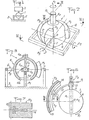
- the device 1 is constituted by an electromechanical converter with several degrees of freedom shown, in its embodiment according to FIG. 2, as capable of authorizing a displacement, an orientation or an adjustment according to three degrees of freedom corresponding to three axes of rotation. These axes or degrees of freedom are references A 1 , A 2 and A 3 , intersecting at a common point 0.
- the electro-mechanical converter 1 comprises a body 4 capable of being physically connected to the device 2 by any suitable means such as a radial extension 4a materializing, preferably, the axis A1.
- the body 4 is mounted on the support 3 by means 5 providing it with freedom of relative movement in rotation, at least partially, on three axes.
- the means 5 are constituted in the form of a universal joint centered on the center O while being disposed inside the body 4 constituted by a hollow body.
- the universal joint comprises a ball joint constituted by a spherical piece 5a secured to the body 4 by a radial rod 5b.
- the part 5a cooperates with a housing 5c, in two assemblable parts, provided at the end of an upright 5d rising from the support 3 and passing through the hollow body 4 through an opening 4b.
- the rod 5b and the upright 5d coincide with the axis A and thus confer a possibility of total and reversible rotation of the body 4 on this axis.
- the means 5 could be produced differently and, for example, the universal joint could be formed directly by an internal housing or body 4 made in two assemblable parts to allow the mounting and dismounting of a spherical part carried by the upright.
- the electromechanical converter also comprises electromagnetic means M or inductors intended to cooperate with the body 4. These means M are carried by a structure 6 rising from the support 2.
- the structure 6 can take any particular form corresponding to the selected application and is shown, in Figure 2, only by way of nonlimiting example in the form of a planar frame.
- the means M are each assigned a degree of freedom or an axis of rotation and for this reason bear the indices 1, 2 and 3 corresponding thereto.
- the electromagnetic means M to M 3 are preferably carried by the structure 6, so that their plane of symmetry corresponds with the diametrical plane P of the body 4, perpendicular to the axis A and passing through the point or center O.
- the connection can be established by suitable members 7 taking into account the possibilities of mounting and dismounting of the means M 1 to M 3 , as well as the specific obligations inherent in their electromagnetic operation.
- the means M are arranged outside of the body 4 which necessarily has a spherical outer surface centered on the center O.
- the electromagnetic means M is arranged so that its plane of influence corresponds to the diametral plane P while the means M 2 and M 3 are arranged in two perpendicular planes so that the plane of influence of each of them is perpendicular on plane P.
- the inductors M 1 to M 3 are each arranged so that their longitudinal plane of symmetry is the plane formed by the two axes other than that on which they act.
- the means M 1 to M 3 can be arranged in three distinct planes having in common only the center of the sphere.
- the electromagnetic means M to M 3 are intended to create radial magnetic fields with tangential displacement, so as to cause, each in its plane of influence, a rotation of the body 4 on the axis perpendicular to such a plane.
- the means M consist of laminated masses 8 (FIGS. 4 and 5) machined so as to delimit, on their surface opposite that of the spherical body 4, teeth 10 between which the windings are placed.
Landscapes
- Engineering & Computer Science (AREA)
- Robotics (AREA)
- Mechanical Engineering (AREA)
- Physics & Mathematics (AREA)
- Chemical & Material Sciences (AREA)
- Combustion & Propulsion (AREA)
- Electromagnetism (AREA)
- Power Engineering (AREA)
- Linear Motors (AREA)
- Manipulator (AREA)
Abstract
Convertisseur électromagnétique, Le convertisseur comprend: - un corps (4) présentant une surface sphérique, - une structure (6) indépendante du corps mais associée à ce dernier par des moyens (5) autorisant un déplacement relatif en rotation sur trois axes, - des moyens électromagnétiques (M) interposés entre le corps et la structure assumant une fonction de coupleurs électromagnétiques provoquant, sur au moins deux axes (1) indépendants une rotation relative, totale et réversible sur un axe et partielle et réversible sur l'autre, entre le corps sphérique et la structure. Application aux commandes de structure orientables.Electromagnetic converter, The converter comprises: - a body (4) having a spherical surface, - a structure (6) independent of the body but associated with the latter by means (5) allowing a relative displacement in rotation on three axes, - electromagnetic means (M) interposed between the body and the structure assuming a function of electromagnetic couplers causing, on at least two independent axes (1) a relative, total and reversible rotation on one axis and partial and reversible on the other, between the spherical body and structure. Application to adjustable structure controls.
Description
La présente invention concerne le problème technique de l'orientation, du déplacement ou du réglage, sur trois degrés de liberté, d'un corps mobile par rapport à une partie ou structure fixe.The present invention relates to the technical problem of orientation, displacement or adjustment, over three degrees of freedom, of a body movable relative to a fixed part or structure.
L'objet de l'invention vise, plus particulièrement, le problème du positionnement d'un corps quelconque par rapport à un référentiel immobile et elle vise, plus spécialement encore, le problème du réglage de l'orientation d'un corps devant, en outre, pouvoir être mobile en rotation sur un axe susceptible d'adopter une orientation quelconque à l'intérieur d'un angle solide prédéterminé.The object of the invention relates, more particularly, to the problem of positioning any body relative to a stationary frame of reference and it aims, more especially still, to the problem of adjusting the orientation of a body in front, in furthermore, being able to be mobile in rotation on an axis capable of adopting any orientation within a predetermined solid angle.
L'invention peut faire l'objet de plusieurs applications différentes et être mise en oeuvre, notamment, pour les robots, les commandes de structures orientables, telles que les radars, les manipulateurs de l'industrie, les commandes de plateforme de guidage, etc...The invention can be the subject of several different applications and can be implemented, in particular, for robots, controls of orientable structures, such as radars, manipulators in industry, controls of guidance platform, etc. ...
Dans les différents domaines ci-dessus, le problème du réglage, de l'orientation ou du déplacement d'un corps mobile, par rapport à une structure fixe sur plusieurs degrés de liberté, s'effectue en mettant en oeuvre un actionneur propre à chaque axe ou degré de liberté concerné. Ceci a pour effet de créer un ensemble lourd, encombrant, onéreux par suite de la multiplication des actionneurs et de leurs moyens de liaison et de commande.In the various fields above, the problem of adjusting, orienting or moving a movable body, relative to a fixed structure over several degrees of freedom, is carried out by implementing an actuator specific to each axis or degree of freedom concerned. This has the effect of creating a heavy, bulky, expensive assembly as a result of the multiplication of actuators and their connection and control means.
En outre, une telle conception conduit à multiplier les inconvénients dûs aux différents actionneurs mis en oeuvre et, notamment, aux problèmes de fiabilité qui leur sont attachés.In addition, such a design leads to multiplying the drawbacks due to the different actuators used and, in particular, to the reliability problems which are attached to them.
Ainsi le brevet FR 2 325 974 montre un dispositif qui, bien que disposant de trois degrés de liberté au plan mécanique ne possède que deux degrés de motorisation électrique au moyen de deux paires de pôles diamétralement opposées dans un même plan horizontal.Thus the
En effet les trois degrés de libertés mécaniques ne peuvent être contrôlés de manière indépendantes.Indeed, the three degrees of mechanical freedom cannot be controlled independently.
Le brevet DE 977 623 montre un dispositif analogue au précédent mais incorporant un moteur électrique supplémentaire pour fournir un troisième degré de liberté. Le troisième moteur est mobile par rapport au support puisque son inducteur et son induit sont montés sur un équipage mobile,ceci réalisant un dispositif lourd dont les parties mobiles ont une forte inertie. Il s'agit donc seulement d'un moteur à un degré de liberté dont le support est stabilisé.Patent DE 977 623 shows a device similar to the previous one but incorporating an additional electric motor to provide a third degree of freedom. The third motor is movable relative to the support since its inductor and its armature are mounted on a mobile assembly, this producing a heavy device whose mobile parts have a high inertia. It is therefore only a motor with a degree of freedom whose support is stabilized.
L'objet de l'invention vise à remplacer les différents actionneurs de la technique antérieure par un moyen unique capable de répondre au problème posé, c'est-à-dire d'autoriser un mouvement possible d'un corps mobile par rapport à une référence fixe sur trois degrés de liberté, l'un de ces degrés de liberté représentant un axe de rotation complète du corps mobile, le mouvement sur chaque degré de liberté pouvant être réalisé indépendamment des mouvements sur les deux autres axes.The object of the invention is to replace the various actuators of the prior art by a single means capable of responding to the problem posed, that is to say of authorizing a possible movement of a movable body relative to a fixed reference on three degrees of freedom, one of these degrees of freedom representing an axis of complete rotation of the mobile body, the movement on each degree of freedom can be achieved independently of the movements on the other two axes.
Un autre objet de l'invention est de prévoir des moyens permettant de réaliser une commande simultanée ou indépendante sur chacun ou plusieurs des degrés de liberté, de façon à provoquer un mouvement résultant qui est directement en rapport avec les composantes individuelles relatives aux degrés de liberté concernés, et qui ne soit pas la simple superposition de trois mouvements distincts obtenus par des moteurs distincts mobiles les uns par rapport aux autres.Another object of the invention is to provide means making it possible to carry out a simultaneous or independent control on each or more of the degrees of freedom, so as to cause a resulting movement which is directly related to the individual components relating to the degrees of freedom which is not the simple superposition of three distinct movements obtained by separate motors movable with respect to each other.
Un objet supplémentaire de l'invention est de fournir, en outre, des moyens pour apprécier le déplacement, le réglage ou l'orientation du corps mobile par rapport à une référence fixe, de façon à pouvoir déterminer, immédiatement, la position spatiale adoptée à la suite de la commande de déplacement exécutée.An additional object of the invention is to provide, in addition, means for assessing the displacement, the adjustment or the orientation of the movable body with respect to a fixed reference, so as to be able to immediately determine the spatial position adopted at following the movement command executed.
Pour atteindre les buts ci-dessus, l'invention a pour objet un convertisseur électromécanique à trois degrés de liberté comprenant :
- .un corps (4) présentant une surface sphérique,
- - une structure (6) indépendante du corps mais associée à ce dernier par des moyens (5) autorisant un déplacement relatif en rotation sur trois axes, caractérisé en ce qu'il comprend : des moyens électromagnétiques (M) interposés entre le corps et la structure, comprenant trois inducteurs indépendants mais solidaires entre eux correspondant à chacun des degrés de liberté, et agissant sur un induit unique par application sur cet induit d'un ensemble de flux croisés pour provoquer, sur trois axes (A) indépendants une rotation relative, totale et réversible sur un axe et partielle et réversible sur les deux autres axes, entre le corps sphérique et la structure.
- .a body (4) having a spherical surface,
- - a structure (6) independent of the body but associated with the latter by means (5) allowing a relative displacement in rotation on three axes, characterized in that it comprises: electromagnetic means (M) interposed between the body and the structure, comprising three independent inductors but integral with each other corresponding to each of the degrees of freedom, and acting on a single armature by application to this armature of a set of crossed fluxes to cause, on three independent axes (A), a relative rotation, total and reversible on one axis and partial and reversible on the other two axes, between the spherical body and the structure.
Diverses autres caractéristiques ressortent de la description faite ci-dessous en référence aux dessins annexés qui montrent, à titre d'exemples non limitatifs, des formes de réalisation de l'objet de l'invention.
- La figure 1 est un schéma montrant l'application de l'invention.
- La figure 2 est une perspective schématique illustrant, à plus grande échelle, l'objet de l'invention.
- La figure 3 est une coupe prise, à plus grande chelle, selon le plan III-III de la figure 2.
- La figure 4 est une vue en plan schématique prise sensiblement selon le plan IV-IV de la figure 2.
- La figure 5 est une vue schématique prise sensiblement selon la ligne V-V de la figure 4.
- La figure 6 montre, plus en détail, un élément constitutif de l'objet de l'invention.
- La figure 7 est une coupe prise selon la ligne VII-VII de la figure 5.
- La figure 8 est une vue schématique analogue à la figure 1 mais montrant un autre exemple d'application.
- Les figures 9 et 10 sont des vues schématiques correspondant à ces coupes diamétrales illustrant deux variantes de réalisation de l'objet de l'invention.
- La figure 1 montre, schématiquement, que l'objet de l'invention, désigné dans son ensemble par la
référence 1, est destiné à être mis en oeuvre pour assurer le déplacement, le réglage ou l'orientation d'un corps mobile 2 quelconque par rapport à un support fixe 3.
- Figure 1 is a diagram showing the application of the invention.
- Figure 2 is a schematic perspective illustrating, on a larger scale, the object of the invention.
- FIG. 3 is a section taken, on a larger scale, along the plane III-III of FIG. 2.
- FIG. 4 is a schematic plan view taken substantially along the plane IV-IV of FIG. 2.
- FIG. 5 is a schematic view taken substantially along the line VV of FIG. 4.
- Figure 6 shows, in more detail, a component of the object of the invention.
- Figure 7 is a section taken on the line VII-VII in Figure 5.
- Figure 8 is a schematic view similar to Figure 1 but showing another example of application.
- Figures 9 and 10 are schematic views corresponding to these diametral sections illustrating two alternative embodiments of the object of the invention.
- Figure 1 shows, schematically, that the object of the invention, designated as a whole by the
reference 1, is intended to be implemented to ensure the displacement, the adjustment or the orientation of anymovable body 2 compared to afixed support 3.
Le dispositif 1 est constitué par un convertisseur électromécanique à plusieurs degrés de liberté représenté, dans sa réalisation selon la figure 2, comme susceptible d'autoriser un déplacement, une orientation ou un réglage selon trois degrés de liberté correspondant à trois axes de rotation. Ces axes ou degrés de liberté sont références A1, A2 et A3, s'in- tersectant en un point commun 0.The
Le convertisseur électro-mécanique 1 comprend un corps 4 susceptible d'être relié physiquement à l'appareil 2 par tout moyen convenable tel qu'un prolongement radial 4a matérialisant, de préférence, l'axe A1.The electro-
Le corps 4 est monté sur le support 3 par des moyens 5 lui procurant une liberté de déplacement relatif en rotation, au moins partielle, sur trois axes. Dans l'exemple illustré par la figure 3, les moyens 5 sont constitués sous la forme d'un joint universel centré sur le centre O en étant disposé à l'intérieur du corps 4 constitué par un corps creux. Le joint universel comprend une rotule constituée par une pièce sphérique 5a solidaire du corps 4 par une tige radiale 5b. La pièce 5a coopère avec un logement 5c, en deux parties assemblables, prévu à l'extrémité d'un montant 5d s'élevant depuis le support 3 est traversant le corps creux 4 par une ouverture 4b.The
La tige 5b et le montant 5d coïncident avec l'axe A et confèrent ainsi une possibilité de rotation totale et réversible du corps 4 sur cet axe.The
Les moyens 5 pourraient être réalisés différemment et, par exemple, le joint universel pourrait être formé directement par un logement interne aucorps 4 réalisé en deux parties assemblables pour permettre le montage et le démontage d'une pièce sphérique portée par le montant.The means 5 could be produced differently and, for example, the universal joint could be formed directly by an internal housing or
Une autre façon de réaliser les moyens5serait de les constituer par quatre galets portés par une cage solidaire du support 3 et coopérant avec une surface extérieure sphérique du corps 4.Another way of making the means 5 would be to constitute them by four rollers carried by a cage secured to the
Le convertisseur électromécanique comprend, par ailleurs des moyens électromagnétiques M ou inducteurs destinés à coopérer avec le corps 4. Ces moyens M sont portés par une structure 6 s'élevant à partir du support 2.The electromechanical converter also comprises electromagnetic means M or inductors intended to cooperate with the
La structure 6 peut prendre toute forme particulière correspondant à l'application retenue et n'est représentée, à la figure 2, qu'à titre d'exemple non limitatif sous la forme d'un cadre plan.The
Les moyens M sont affectés chacun à un degré de liberté ou à un axe de rotation et portent, pour cette raison les indices 1, 2 et 3 leur correspondant. Les moyens électromagnétiques M à M3 sont, de préférence, portés par la structure 6, de manière que leur plan de symétrie corresponde avec le plan diamétral P du corps 4, perpendiculaire à l'axe A et passant par le point ou centre O. A titre d'exemple, la liaison peut être établie par des membrures convenables 7 tenant compte des possibilités de montage et démontage des moyens M1 à M3, ainsi que des obligations spécifiques inhérentes à leur fonctionnement électromagnétique.The means M are each assigned a degree of freedom or an axis of rotation and for this reason bear the
Dans l'exemple de réalisation selon les figures 1 à 3, les moyens M sont disposés à l'extérieur du corps 4 qui présente, obligatoirement, une surface extérieure sphérique centrée sur le centre O.In the exemplary embodiment according to FIGS. 1 to 3, the means M are arranged outside of the
Le moyen électromagnétique M est disposé de manière que son plan d'influence corresponde au plan diamétral P alors que les moyens M2 et M3 sont disposés dans deux plans perpendiculaires de telle sorte que le plan d'influence de chacun d'eux soit perpendiculaire au plan P.The electromagnetic means M is arranged so that its plane of influence corresponds to the diametral plane P while the means M 2 and M 3 are arranged in two perpendicular planes so that the plane of influence of each of them is perpendicular on plane P.
De façon plus générale, les inducteurs Mlà M3sont disposés chacun de telle sorte que leur plan de symétrie longitudinale soit le plan formé par les deux axes autres que celui sur lequel ils agissent.More generally, the inductors M 1 to M 3 are each arranged so that their longitudinal plane of symmetry is the plane formed by the two axes other than that on which they act.
Plus généralement encore, les moyens M1 à M3 peuvent être disposés dans trois plans distincts n'ayant en commun que le centre de la sphère.More generally still, the means M 1 to M 3 can be arranged in three distinct planes having in common only the center of the sphere.
Les moyens électromagnétiques M à M3, sont destinés à créer des champs magnétiques radiaux à déplacement tangentiel, de façon à provoquer, chacun dans son plan d'influence, une rotation du corps 4 sur l'axe perpendiculaire à un tel plan. Les moyens M sont constitués de masses feuilletées 8 (fig. 4 et 5) usinées de manière à délimiter, sur leur surface en regard de celle sphérique du corps 4, des dents 10 entre lesquelles sont placés des bobinages.The electromagnetic means M to M 3 are intended to create radial magnetic fields with tangential displacement, so as to cause, each in its plane of influence, a rotation of the
La construction de ces moyens M1à M3 doit être considérée comme du domaine de l'homme de métier pour ce qui concerne le choix des épaisseurs et de l'alliage des différentes plaques entrant dans la constitution des masses feuilletées, le choix des isolants les séparant et le choix des caractéristiques des bobinages qui leur sont associés. La seule exigence devant être maintenue est la réalisation de moyens M à M3 présentant une surface en portion de surface sphérique qui est, dans le cas présent, concave, de manière à pouvoir délimiter,;avec la surface sphérique convexe du corps 4, un entrefer de valeur constante.The construction of these means M 1 to M 3 must be considered to be the domain of a person skilled in the art with regard to the choice of thicknesses and of the alloy of the various plates used in the constitution of the laminated masses, the choice of insulators separating them and the choice of characteristics as the coils associated with them. The only requirement to be maintained is the production of means M to M 3 having a spherical surface portion portion which is, in this case, concave, so as to be able to delimit ; with the convex spherical surface of the
Les inducteurs M1à Mgpeuvent être formés d'une entité matérielle unique ainsi que le montre les modes de réalisation des figures 1 à 9 ou de plusieurs entités séparées comme par exemple le mode de réalisation de la figure 10.The inductors M1 to Mg can be formed of a single material entity as shown in the embodiments of FIGS. 1 to 9 or of several separate entities such as for example the embodiment of FIG. 10.
Les trois inducteurs M1, M2, M3 agissent donc indépendamment sur l'induit unique formé par le corps sphérique et par combinaison de trois flux croisés qu'ils appliquent sur l'induit permettent un déplacement du corps 4 par rapport à eux-même ou inversement d'eux-même par rapport au corps 4, selon trois degrés de liberté.The three inductors M 1 , M 2 , M 3 therefore act independently on the single armature formed by the spherical body and by combination of three crossed fluxes which they apply to the armature allow the
En effet les flux produits par les trois inducteurs, bien que se combinant en agissant sur le même induit, conservent chacun la spécificité de leur action et donc l'indépendance de leurs effets électromécaniques.Indeed, the fluxes produced by the three inductors, although combining by acting on the same armature, each retain the specificity of their action and therefore the independence of their electromechanical effects.
De manière à pouvoir établir un couplage électromagnétique entre les moyens M1à M3 et le corps sphérique 4, il peut être prévu de réaliser ce dernier de plusieurs façons différentes.So as to be able to establish an electromagnetic coupling between the means M 1 to M3 and the
Le corps 4 peut présenter une surface extérieure lisse et être réalisé en une matière ferromagnétique massive, en partie au moins en matière ferromagnétique recouverte d'une couche de matière conductrice telle que cuivre ou aluminium ou encore, en une matière amagnétique associée à un revêtement de matière conductrice comme par exemple le cuivre ou l'aluminium.The
Le convertisseur électromagnétique représente alors un dispositif moteur asynchrone à réluctance constante.The electromagnetic converter then represents an asynchronous constant reluctance motor device.
En associant au dispositif un apport de puissance réactive réalisé par exemple au moyen de condensateurs électriques, reliés électriquement aux sorties des inducteurs M1 à M3 le dispositif peut fonctionner en génératrice asynchrone lors des phases de ralentissement du mouvement du corps sphérique.By associating with the device a reactive power supply produced for example by means of electric capacitors, electrically connected to the outputs of the inductors M 1 to M 3 the device can operate as an asynchronous generator during the phases of slowing down of the movement of the spherical body.
Le corps 4 peut aussi présenter des encoches délimitant des plots prévus de manière à réaliser dans chacune des directions, avec les dents magnétiques 10 des moyens inducteurs M, un effet de Vernier électromagnétique. Le corps 4 peut alors être en un matériau ferromagnétique non conducteur, en un matériau ferromagnétique conducteur ou, encore, en un matériau ferromagnétique non conducteur revêtu d'une couche de matière conductrice. Les intervalles entre les plots peuvent être occupés par des aimants et/ou par des bobines de polarisation.The
Ces bobines peuvent être alimentées au moyen d'un système bagues- balais.These coils can be fed by means of a brush-ring system.
Le convertisseur électromécanique. représente alors un dispositif à couplage synchrone et à réluctance variable, en fonctionnement moteur ou générateur.The electromechanical converter. then represents a device with synchronous coupling and variable reluctance, in motor or generator operation.
Une combinaison de ces deux techniques permet de disposer d'un convertisseur asynchrone synchronisé.A combination of these two techniques provides a synchronized asynchronous converter.
Ceci peut être réalisé notammertten prévoyant soit un corps (4) réalisé en matériau ferromagnétique conducteur encoché revêtu ou non d'une couche conductrice, soit de façon équivalente un corps (4) réalisé en un matériau ferromagnétique non conducteur revêtu d'une couche conductrice, soit le corps (4) réalisé en un matériau ferromagnétique non conducteur mais comportant des enroulements encourt-circuit.This can be achieved in particular by providing either a body (4) made of a ferromagnetic notched conductive material coated or not with a conductive layer, or equivalently a body (4) made of a non-conductive ferromagnetic material coated with a conductive layer, or the body (4) made of a non-conductive ferromagnetic material but comprising over-circuit windings.
L'alimentation des inducteurs M est associée avec des courants d'intensité variable en fonction du déplacement à obtenir. Une commande pas à pas peut ainsi être obtenue dans le cas de construction en dispositif moteur synchrone.The supply of the inductors M is associated with currents of variable intensity depending on the displacement to be obtained. A step-by-step command can thus be obtained in the case of construction in synchronous motor device.
Ainsi, en référence de la figure 2, on conçoit que l'alimentation du moyen électromagnétique M permet de faire tourner le corps sphérique 4 par les moyens 5 sur l'axe ou le degré de liberté A1, dans un sens ou dans l'autre, et sur une rotation inférieure, égale ou supérieure à 360°.Thus, with reference to FIG. 2, it can be understood that the supply of the electromagnetic means M makes it possible to rotate the
L'alimentation du moyen M2 permet de commander la rotation du corps sphérique par les moyens 5 sur l'axe A2 avec une amplitude angulaire correspondant à la liberté de déplacement autorisée, soit par les moyens 5, soit par l'encombrement général que présentent, les moyens M à M3. Il est certain que l'alimentation du moyen M2 peut être établie indépendamment ou successivement à celle du moyen M lorsqu'il est souhaité entraîner le corps 4 en déplacement indépendant sur chacun des axes ou degrés de liberté ou, encore, en un mouvement résultant correspondant aux actions combinées d'au moins deux déplacements sur deux degrés de liberté.The supply of the means M 2 makes it possible to control the rotation of the spherical body by the means 5 on the axis A 2 with an angular amplitude corresponding to the freedom of movement authorized, either by the means 5, or by the general bulk that present, the means M to M 3 . It is certain that the supply of the means M 2 can be established independently or successively to that of the means M when it is desired to drive the
L'alimentation du moyen M3 permet de faire tourner le corps sphérique 4 par les moyens 5 sur l'axe ou le degré de liberté A3 avec les mêmes conditions que celles correspondant au moteur M2 .The supply of the means M 3 makes it possible to rotate the
Ainsi, le convertisseur électromécanique objet de l'invention, constitué comme décrit ci-dessus, permet, en étant interposé entre un support 3 et un produit, objet du dispositif 2 mobile, de commander le déplacement, l'orientation ou le réglage de position de ce produit en ne faisant intervenir qu'une structure motrice unique dont l'encombrement est limité par rapport aux solutions traditionnelles comportant autant d'actionneurs qu'il existe de degrés de liberté.Thus, the electromechanical converter object of the invention, constituted as described above, allows, by being interposed between a
Par le moyen de l'invention, il devient ainsi possible de faire tourner le produit ou objet 2 sur l'axe A1, en rotation continue ou non, dans un sens ou dans l'âutre, et de régler la position de cet axe à l'intérieur d'un cône défini par un angle solide déterminé par l'amplitude de déplacement susceptible d'être conférée en rotation sur les axes A2 et A3 .By means of the invention, it thus becomes possible to rotate the product or
Selon un développement de l'invention, il est prévu de faire comporter au convertisseur électromécanique un détecteur 11 de de position propre à chacun des degrés de liberté. 1 According to a development of the invention, provision is made for the electromechanical converter to comprise a
Les détecteurs de position 112 - 113 correspondant aux axes A2 et A3 peuvent être, par exemple, de type de celui représenté schématiquement aux figures 6 et 7. Selon ces dernières, chaque détecteur 11 comprend un bras 12 qui est monté sur le prolongement 4a par l'intermédiaire d'une bague de rotation 13. Le bras 12 comporte, à son extrémité opposée, une réglette 14 qui est susceptible de coulisser dans une glissière 15 occupant sur la struc- tur 6 une position fixe correspondant au plan d'influence du moyen M auquel le détecteur correspond. La réglette 14 est associée au bras 12 par un pivot 16 dont l'axe est dirigé vers le centre O. La réglette 14 comporte, sur l'une de ses parties constitutives, des fentes de longueur déterminée qui sont destinées à coopérer avec des moyens de lecture, tels que des phototransistors adaptés sur la glissière 15. Les fentes sont échelonnées de manière à pouvoir déterminer, à la fois, l'amplitude et le sens du déplacement à partir d'une position neutre correspondant, par exemple, à un alignement du prolongement 4 avec la verticale.The position detectors 11 2 - 11 3 corresponding to the axes A 2 and A 3 may, for example, be of the type shown diagrammatically in FIGS. 6 and 7. According to the latter, each
En référence à la figure 6, on constate que le corps sphérique 4 est libre de rotation sur l'axe A mais que tout déplacement angulaire de cet axe peut ainsi être détecté au moyen des capteurs 112 - 113. En effet, si par exemple l'alimentation du moyen électromécanique M2 est assurée pour entraîner la rotation du corps sphérique 4 sur l'axe A2 dans l'un ou l'autre yens de la flèche F, la réglette 14 se déplace à l'intérieur de la glissière 15 et fournit, par la coopération des fentes et des moyens de lecture, l'information correspondante à distance permettant de détecter l'amplitude ou la nouvelle position atteinte par le corps sphérique 4.With reference to FIG. 6, it can be seen that the
Les informations délivrées par les détecteurs correspondant aux axes A2 et A3 permettent donc de posséder une connaissance exacte de la position spatiale du prolongement 4a et, par conséquent, du produit ou objet 3.The information delivered by the detectors corresponding to the axes A 2 and A 3 therefore makes it possible to have an exact knowledge of the spatial position of the
La connaissance de l'orientation sur l'axe A est fournie par un détecteur de position M3 correspondant à l'axe A1 , constitué par un détecteur de conception classique, tel qu'une roue codée, fixée sur le prolongement 4a et associée à un lecteur optique ou magnétique par exemple fixé sur l'une des bagues 13.The knowledge of the orientation on the axis A is provided by a position detector M 3 corresponding to the axis A 1 , constituted by a detector of conventional design, such as a coded wheel, fixed on the
Dans ce qui précède, il est indiqué que, selon la figure 1, le convertisseur électromécanique 1 est interposé entre un support 3 fixe et un produit ou objet 2 mobile. Il doit être considéré que l'objet de l'invention peut également être mis en oeuvre pour une disposition inversée consistant à rendre le corps 4 fixe et la structure 6 mobile lorsqu'elle est conçue en tant que plateforme de montage ou d'adaptation d'ensembles ou de produits divers, comme cela apparaît à la figure 8.In the foregoing, it is indicated that, according to FIG. 1, the
Le fonctionnement décrit ci-dessus intervient, alors de même façon pour produire une rotation relative entre le corps sphérique 4 et la structure 6, dès que l'un quelconque des moyens M est alimenté.The operation described above occurs, then in the same way to produce a relative rotation between the
Dans certaines applications, il peut être envisagé de mettre en oeuvre le convertisseur électromécanique de l'invention pour des dispositifs pour lesquels l'encombrement, représenté par la structure 6 décrite à la figure 2, peut être rédhibitoire.In certain applications, it can be envisaged to use the electromechanical converter of the invention for devices for which the space requirement, represented by the
Dans un tel cas, comme illustré par la figure 9, les moyens électromagnétiques M1 à M peuvent être conçus pour que la surface sphérique qu'ils délimitent soit extérieure et non plus intérieure, de manière à pouvoir coopérer avec une surface sphérique interne du corps creux 4. La structure porteuse des moyens électromagnétiques se présente alors comme une armature, par exemple, à bras 17 rayonnants s'étendant à partir du montant 5d. Les bras rayonnants 17 et le montant 5d sont, de préférence, tubulaires pour assurer l'acheminement et la protection des conducteurs dlalimentation des moyens électromagnétiques M.In such a case, as illustrated in FIG. 9, the electromagnetic means M1 to M can be designed so that the spherical surface which they delimit is external and no longer internal, so as to be able to cooperate with an internal spherical surface of the
Dans cet exemple de réalisation, le corps 4 peut être mobile par rapport à l'armature 6 fixe ou inversement.In this exemplary embodiment, the
La figure 10 montre qu'une disposition mixte peut également être retenue en faisant comporter certains des moyens M à l'intérieur du corps 4 et d'autres moyens à l'extérieur de ce dernier, tout en demeurant tous solidaires sur les plans mécanique et électromagnétique. Ceci peut être le cas, notamment, lorsque chacun des moyens M1 à M3 est formé de deux éléments constitutifs travaillant en couple pour produire le déplacement du corps 4 ou de la structure 6 sur un axe ou un degré de liberté.FIG. 10 shows that a mixed arrangement can also be adopted by having some of the means M inside the
Dans ce type de configuration lorsque la surface extérieure du corps mobile (4) est lisse et sa surface intérieure encochée (ou inversement), le convertisseur peut réaliser un mouvement synchrone sur un axe et asynchrone sur les deux autres axes ou réciproquement suivant la répartition interne et externe des moyens électromagnétiques M à M3.In this type of configuration when the external surface of the mobile body (4) is smooth and its internal surface notched (or vice versa), the converter can perform a synchronous movement on one axis and asynchronous on the other two axes or vice versa according to the internal distribution and external of the electromagnetic means M to M 3 .
Un des avantages, de l'invention est de concentrer les actions électromagnétiques de trois inducteurs sur une structure mobile unique, ce qui permet la suppression, en comparaison des dispositifs existants, d'un certain nombre de liaisons mécaniques, diminuant de ce fait les frottements et les jeux mécaniques.One of the advantages of the invention is to concentrate the electromagnetic actions of three inductors on a single mobile structure, which allows the elimination, in comparison with existing devices, of a certain number of mechanical connections, thereby reducing friction and the mechanical games.
Un autre avantage de l'invention réside dans le fait que les inducteurs tous solidaires entre eux sont montés sur un seul et même support ce qui permet d'accroître notablement la compacité du dispositif.Another advantage of the invention lies in the fact that the inductors, all integral with one another, are mounted on one and the same support, which makes it possible to significantly increase the compactness of the device.
Claims (11)
caractérisé en ce qu'il comprend :
characterized in that it comprises:
Applications Claiming Priority (2)
| Application Number | Priority Date | Filing Date | Title |
|---|---|---|---|
| FR8220450A FR2537301B1 (en) | 1982-12-07 | 1982-12-07 | ELECTRO-MECHANICAL CONVERTER WITH MULTIPLE DEGREES OF FREEDOM |
| FR8220450 | 1982-12-07 |
Publications (2)
| Publication Number | Publication Date |
|---|---|
| EP0113267A1 true EP0113267A1 (en) | 1984-07-11 |
| EP0113267B1 EP0113267B1 (en) | 1986-04-16 |
Family
ID=9279847
Family Applications (1)
| Application Number | Title | Priority Date | Filing Date |
|---|---|---|---|
| EP83402345A Expired EP0113267B1 (en) | 1982-12-07 | 1983-12-06 | Electromechanical converter with several degrees of freedom |
Country Status (4)
| Country | Link |
|---|---|
| US (1) | US4634889A (en) |
| EP (1) | EP0113267B1 (en) |
| DE (1) | DE3363098D1 (en) |
| FR (1) | FR2537301B1 (en) |
Cited By (10)
| Publication number | Priority date | Publication date | Assignee | Title |
|---|---|---|---|---|
| EP0231109A2 (en) * | 1986-01-24 | 1987-08-05 | Kabushiki Kaisha Toshiba | Non-contact positioning device |
| FR2606225A1 (en) * | 1986-10-30 | 1988-05-06 | France Etat Armement | ELECTROMAGNETIC ACTUATOR WITH TWO ENTREPRERS |
| WO1988005996A2 (en) * | 1987-02-17 | 1988-08-25 | Martin Marietta Corporation | Triaxis stabilized platform |
| FR2658673A1 (en) * | 1990-02-22 | 1991-08-23 | Sagem | DIRECT CURRENT ELECTRIC MOTOR WITH TWO AXIS OF ROTATION, IN PARTICULAR FOR VIEWFINDER. |
| EP0526774A2 (en) * | 1991-07-31 | 1993-02-10 | Mitsubishi Jukogyo Kabushiki Kaisha | Electric motor having a spherical rotor and its application apparatus |
| WO1995007793A2 (en) * | 1993-09-13 | 1995-03-23 | United Technologies Corporation | Force and position controlled manipulator |
| EP1529256B1 (en) * | 2002-08-06 | 2010-10-06 | Rockwell Collins, Inc. | Direct drive controller with haptic feedback |
| CN104882250A (en) * | 2015-06-02 | 2015-09-02 | 梁少文 | Transformer provided with alarm convenient to detach and maintain |
| US20180264574A1 (en) * | 2017-03-17 | 2018-09-20 | Faurecia Emissions Control Technologies, Germany Gmbh | Joining device and method for producing an exhaust gas system |
| WO2021243515A1 (en) * | 2020-06-01 | 2021-12-09 | 大连理工大学 | Electromagnetic driving two-degrees of freedom spherical robot wrist and control method thereof |
Families Citing this family (18)
| Publication number | Priority date | Publication date | Assignee | Title |
|---|---|---|---|---|
| US4908558A (en) * | 1988-04-22 | 1990-03-13 | Contraves Goerz Corporation | Spherical motion simulator |
| US5447409A (en) * | 1989-10-20 | 1995-09-05 | Applied Materials, Inc. | Robot assembly |
| ES2130295T3 (en) * | 1989-10-20 | 1999-07-01 | Applied Materials Inc | ROBOT TYPE DEVICE. |
| US5280225A (en) * | 1992-04-20 | 1994-01-18 | Motorola, Inc. | Method and apparatus for multi-axis rotational motion |
| US5402049A (en) * | 1992-12-18 | 1995-03-28 | Georgia Tech Research Corporation | System and method for controlling a variable reluctance spherical motor |
| US5410232A (en) * | 1992-12-18 | 1995-04-25 | Georgia Tech Research Corporation | Spherical motor and method |
| US5376862A (en) * | 1993-01-28 | 1994-12-27 | Applied Materials, Inc. | Dual coaxial magnetic couplers for vacuum chamber robot assembly |
| US6664666B2 (en) * | 1998-12-23 | 2003-12-16 | Engineering Matters, Inc. | Motor assembly allowing output in multiple degrees of freedom |
| US6683581B2 (en) * | 2000-12-29 | 2004-01-27 | Bellsouth Intellectual Property Corporation | Antenna alignment devices |
| GB2388064B (en) * | 2002-05-01 | 2005-06-08 | Kfh Design Ltd | Precise positioning of an object |
| EP2271256B1 (en) * | 2008-03-27 | 2012-08-01 | Koninklijke Philips Electronics N.V. | Method and system for measuring an object of interest |
| CN101732870A (en) * | 2008-11-07 | 2010-06-16 | 鸿富锦精密工业(深圳)有限公司 | Simulated eye |
| US8498741B2 (en) * | 2009-09-22 | 2013-07-30 | Gm Global Technology Operations | Dexterous humanoid robotic wrist |
| NL2005011C2 (en) * | 2010-07-01 | 2012-01-03 | Be-Kking Man B V | ROTATING MACHINE FOR COMPRESSION AND DECOMPRESSION. |
| US9287760B2 (en) | 2012-08-20 | 2016-03-15 | Remec Broadband Wireless Holdings, Inc. | Highly reliable actuator with multiple degrees of freedom and method for moving a payload using the actuator |
| TWI497876B (en) * | 2013-01-31 | 2015-08-21 | Univ Chung Hua | Electromagnetic drive spheres and their vehicles |
| US10406696B2 (en) * | 2014-07-29 | 2019-09-10 | Hewlett Packard Enterprise Development Lp | Lockable connector device |
| CN112025760B (en) * | 2020-09-01 | 2023-01-31 | 重庆邮电大学 | Electromagnetic driving mechanical joint |
Citations (10)
| Publication number | Priority date | Publication date | Assignee | Title |
|---|---|---|---|---|
| FR674513A (en) * | 1928-05-12 | 1930-01-29 | Acec | Improvements to the start-up and synchronization processes of cascaded switches |
| CH312381A (en) * | 1952-06-05 | 1955-12-31 | Philips Nv | Reversible AC motor. |
| DE977623C (en) * | 1962-09-09 | 1967-11-30 | Telefunken Patent | Torque transmitter |
| FR2040907A5 (en) * | 1969-04-16 | 1971-01-22 | Vierne Andre | |
| FR2180551A1 (en) * | 1972-04-20 | 1973-11-30 | Calka Maurice | |
| FR2198299A1 (en) * | 1972-09-06 | 1974-03-29 | Denis Michel | |
| FR2325974A1 (en) * | 1975-09-24 | 1977-04-22 | Marconi Co Ltd | STABILIZED BASE FOR CARRYING A DEVICE ON A LOCOMOTION DEVICE |
| FR2419341A1 (en) * | 1978-03-11 | 1979-10-05 | Vyzk Vyvojovy Ustav Zavodu | DEVICE FOR THE TRANSPORT OF THE WEFT INTRODUCTION ELEMENTS, IN PARTICULAR IN STEP Looms |
| FR2452193A1 (en) * | 1979-03-23 | 1980-10-17 | Gradient | Spherical motor for servo-mechanism - has at least two degrees of freedom and rotor enclosed within four sectioned inductor shell |
| DE3122695A1 (en) * | 1981-06-06 | 1983-01-05 | Herbert Prof. Dr.-Ing. 3300 Braunschweig Weh | Asynchronous motors having large repulsive normal forces |
Family Cites Families (6)
| Publication number | Priority date | Publication date | Assignee | Title |
|---|---|---|---|---|
| US3398341A (en) * | 1965-02-16 | 1968-08-20 | Army Usa | Active compensation network to stabilize an inertial platform |
| US3441936A (en) * | 1965-03-29 | 1969-04-29 | Lear Siegler Inc | Spherically mounted floating radiation reflector |
| CA1034393A (en) * | 1976-10-13 | 1978-07-11 | Henry J. Taylor | Powered wrist joint |
| US4143212A (en) * | 1976-10-18 | 1979-03-06 | Tokyo Shibaura Electric Co., Ltd. | Sealed storage battery |
| SU657539A1 (en) * | 1977-01-17 | 1979-04-15 | Московский Ордена Ленина Энергетический Институт | Two-coordinate stepping motor |
| US4437047A (en) * | 1981-07-13 | 1984-03-13 | Hughes Aircraft Company | System for autonomous earth-pointing acquisition of a dual-spin satellite |
-
1982
- 1982-12-07 FR FR8220450A patent/FR2537301B1/en not_active Expired
-
1983
- 1983-12-06 DE DE8383402345T patent/DE3363098D1/en not_active Expired
- 1983-12-06 EP EP83402345A patent/EP0113267B1/en not_active Expired
- 1983-12-07 US US06/558,980 patent/US4634889A/en not_active Expired - Fee Related
Patent Citations (10)
| Publication number | Priority date | Publication date | Assignee | Title |
|---|---|---|---|---|
| FR674513A (en) * | 1928-05-12 | 1930-01-29 | Acec | Improvements to the start-up and synchronization processes of cascaded switches |
| CH312381A (en) * | 1952-06-05 | 1955-12-31 | Philips Nv | Reversible AC motor. |
| DE977623C (en) * | 1962-09-09 | 1967-11-30 | Telefunken Patent | Torque transmitter |
| FR2040907A5 (en) * | 1969-04-16 | 1971-01-22 | Vierne Andre | |
| FR2180551A1 (en) * | 1972-04-20 | 1973-11-30 | Calka Maurice | |
| FR2198299A1 (en) * | 1972-09-06 | 1974-03-29 | Denis Michel | |
| FR2325974A1 (en) * | 1975-09-24 | 1977-04-22 | Marconi Co Ltd | STABILIZED BASE FOR CARRYING A DEVICE ON A LOCOMOTION DEVICE |
| FR2419341A1 (en) * | 1978-03-11 | 1979-10-05 | Vyzk Vyvojovy Ustav Zavodu | DEVICE FOR THE TRANSPORT OF THE WEFT INTRODUCTION ELEMENTS, IN PARTICULAR IN STEP Looms |
| FR2452193A1 (en) * | 1979-03-23 | 1980-10-17 | Gradient | Spherical motor for servo-mechanism - has at least two degrees of freedom and rotor enclosed within four sectioned inductor shell |
| DE3122695A1 (en) * | 1981-06-06 | 1983-01-05 | Herbert Prof. Dr.-Ing. 3300 Braunschweig Weh | Asynchronous motors having large repulsive normal forces |
Non-Patent Citations (1)
| Title |
|---|
| SOVIET INVENTIONS ILLUSTRATED, Derwent, semaine C01, 13.02.1980 * |
Cited By (18)
| Publication number | Priority date | Publication date | Assignee | Title |
|---|---|---|---|---|
| EP0231109A2 (en) * | 1986-01-24 | 1987-08-05 | Kabushiki Kaisha Toshiba | Non-contact positioning device |
| EP0231109A3 (en) * | 1986-01-24 | 1989-03-08 | Kabushiki Kaisha Toshiba | Non-contact positioning device |
| FR2606225A1 (en) * | 1986-10-30 | 1988-05-06 | France Etat Armement | ELECTROMAGNETIC ACTUATOR WITH TWO ENTREPRERS |
| WO1988005996A2 (en) * | 1987-02-17 | 1988-08-25 | Martin Marietta Corporation | Triaxis stabilized platform |
| WO1988005996A3 (en) * | 1987-02-17 | 1988-09-22 | Martin Marietta Corp | Triaxis stabilized platform |
| FR2658673A1 (en) * | 1990-02-22 | 1991-08-23 | Sagem | DIRECT CURRENT ELECTRIC MOTOR WITH TWO AXIS OF ROTATION, IN PARTICULAR FOR VIEWFINDER. |
| EP0453328A2 (en) * | 1990-02-22 | 1991-10-23 | Societe D'applications Generales D'electricite Et De Mecanique Sagem | D.C. motor with two axis of rotation, in particular for a view finder |
| EP0453328A3 (en) * | 1990-02-22 | 1991-10-30 | Societe D'applications Generales D'electricite Et De Mecanique Sagem | D.c. motor with two axis of rotation, in particular for a view finder |
| EP0526774A2 (en) * | 1991-07-31 | 1993-02-10 | Mitsubishi Jukogyo Kabushiki Kaisha | Electric motor having a spherical rotor and its application apparatus |
| US5413010A (en) * | 1991-07-31 | 1995-05-09 | Mitsubishi Jukogyo Kabushiki Kaisha | Electric motor having a spherical rotor and its application apparatus |
| EP0526774B1 (en) * | 1991-07-31 | 1996-03-20 | Mitsubishi Jukogyo Kabushiki Kaisha | Electric motor having a spherical rotor and its application apparatus |
| WO1995007793A2 (en) * | 1993-09-13 | 1995-03-23 | United Technologies Corporation | Force and position controlled manipulator |
| WO1995007793A3 (en) * | 1993-09-13 | 1995-11-30 | United Technologies Corp | Force and position controlled manipulator |
| EP1529256B1 (en) * | 2002-08-06 | 2010-10-06 | Rockwell Collins, Inc. | Direct drive controller with haptic feedback |
| CN104882250A (en) * | 2015-06-02 | 2015-09-02 | 梁少文 | Transformer provided with alarm convenient to detach and maintain |
| US20180264574A1 (en) * | 2017-03-17 | 2018-09-20 | Faurecia Emissions Control Technologies, Germany Gmbh | Joining device and method for producing an exhaust gas system |
| WO2021243515A1 (en) * | 2020-06-01 | 2021-12-09 | 大连理工大学 | Electromagnetic driving two-degrees of freedom spherical robot wrist and control method thereof |
| US11446814B2 (en) | 2020-06-01 | 2022-09-20 | Dalian University Of Technology | Electromagnetic drive spherical robotic wrist with two degrees of freedom and control method therefor |
Also Published As
| Publication number | Publication date |
|---|---|
| US4634889A (en) | 1987-01-06 |
| EP0113267B1 (en) | 1986-04-16 |
| FR2537301B1 (en) | 1986-01-24 |
| DE3363098D1 (en) | 1986-05-22 |
| FR2537301A1 (en) | 1984-06-08 |
Similar Documents
| Publication | Publication Date | Title |
|---|---|---|
| EP0113267B1 (en) | Electromechanical converter with several degrees of freedom | |
| EP0616665B1 (en) | Magnetic bearing and mechanical stop device for positioning a rotating body in relation to a stator body | |
| EP0587685B1 (en) | Low-cost stepping or synchronous motor | |
| EP0251918B1 (en) | Angle position sensor and appliance for determining the angular position using several of said sensors | |
| EP0641061B1 (en) | Magnetic bearing device for tipping a rotating body with respect to a stator body | |
| FR2607315A1 (en) | ELECTROMAGNETIC CONTROL ORDER | |
| EP2990375B1 (en) | Electromagnetically actuated mems | |
| FR2742497A1 (en) | MAGNETIC BEARING WITH ALTERNATE ACTUATORS AND SENSORS | |
| WO1986004534A1 (en) | Method and device for displacing the impact point of a laser beam on a part | |
| CH699897A2 (en) | SCARA-type parallel robot. | |
| FR2732734A1 (en) | MINIATURE MAGNETIC BEARING HAS AT LEAST ONE ACTIVE AXIS | |
| EP2071708A1 (en) | Motorised slewing ring | |
| EP0401084B1 (en) | Device with several angle position sensors | |
| WO1987007757A1 (en) | Electromagnetic actuation device | |
| FR2894341A1 (en) | ELECTROMECHANICAL DEVICE COMPRISING A MEMBER WHICH CAN ROTATE AROUND AT LEAST ONE FIRST AND A SECOND AXIS OF ROTATION | |
| EP2741406B1 (en) | Stepping motor with double rotor | |
| CH493960A (en) | Electromagnetic drive device comprising an armature with adjustable equilibrium position | |
| WO1985004512A1 (en) | Multipolar magnetization device | |
| EP0790540B1 (en) | Electromagnetic transductor with multipolar permanent magnets | |
| FR2580051A1 (en) | ||
| FR3032570A1 (en) | SWIVEL ELECTRIC MOTOR | |
| FR2713292A1 (en) | Positioning system controlling orientation of rotating body such as scanning mirror on magnetic bearing | |
| FR3106449A1 (en) | Electric transverse flux machine with permanent magnets at the stator | |
| FR2696059A1 (en) | Motor-couple with flat disc and angular movement control for e.g scanning mirror - has inductor of two magnetic armatures circumferentially and without contact to radial periphery with axial projections | |
| FR2571906A1 (en) | Two-stage torque motor |
Legal Events
| Date | Code | Title | Description |
|---|---|---|---|
| PUAI | Public reference made under article 153(3) epc to a published international application that has entered the european phase |
Free format text: ORIGINAL CODE: 0009012 |
|
| AK | Designated contracting states |
Designated state(s): CH DE FR GB IT LI NL SE |
|
| 17P | Request for examination filed |
Effective date: 19840622 |
|
| GRAA | (expected) grant |
Free format text: ORIGINAL CODE: 0009210 |
|
| AK | Designated contracting states |
Kind code of ref document: B1 Designated state(s): CH DE FR GB IT LI NL SE |
|
| ITF | It: translation for a ep patent filed |
Owner name: BUGNION S.P.A. |
|
| REF | Corresponds to: |
Ref document number: 3363098 Country of ref document: DE Date of ref document: 19860522 |
|
| PLBE | No opposition filed within time limit |
Free format text: ORIGINAL CODE: 0009261 |
|
| STAA | Information on the status of an ep patent application or granted ep patent |
Free format text: STATUS: NO OPPOSITION FILED WITHIN TIME LIMIT |
|
| 26N | No opposition filed | ||
| ITTA | It: last paid annual fee | ||
| PGFP | Annual fee paid to national office [announced via postgrant information from national office to epo] |
Ref country code: NL Payment date: 19911231 Year of fee payment: 9 |
|
| PGFP | Annual fee paid to national office [announced via postgrant information from national office to epo] |
Ref country code: DE Payment date: 19920226 Year of fee payment: 9 |
|
| PGFP | Annual fee paid to national office [announced via postgrant information from national office to epo] |
Ref country code: CH Payment date: 19921119 Year of fee payment: 10 |
|
| PGFP | Annual fee paid to national office [announced via postgrant information from national office to epo] |
Ref country code: SE Payment date: 19921123 Year of fee payment: 10 |
|
| PGFP | Annual fee paid to national office [announced via postgrant information from national office to epo] |
Ref country code: GB Payment date: 19921124 Year of fee payment: 10 |
|
| PG25 | Lapsed in a contracting state [announced via postgrant information from national office to epo] |
Ref country code: NL Effective date: 19930701 |
|
| NLV4 | Nl: lapsed or anulled due to non-payment of the annual fee | ||
| PG25 | Lapsed in a contracting state [announced via postgrant information from national office to epo] |
Ref country code: DE Effective date: 19930901 |
|
| PGFP | Annual fee paid to national office [announced via postgrant information from national office to epo] |
Ref country code: FR Payment date: 19931007 Year of fee payment: 11 |
|
| PG25 | Lapsed in a contracting state [announced via postgrant information from national office to epo] |
Ref country code: GB Effective date: 19931206 |
|
| PG25 | Lapsed in a contracting state [announced via postgrant information from national office to epo] |
Ref country code: SE Effective date: 19931207 |
|
| PG25 | Lapsed in a contracting state [announced via postgrant information from national office to epo] |
Ref country code: LI Effective date: 19931231 Ref country code: CH Effective date: 19931231 |
|
| GBPC | Gb: european patent ceased through non-payment of renewal fee |
Effective date: 19931206 |
|
| REG | Reference to a national code |
Ref country code: CH Ref legal event code: PL |
|
| EUG | Se: european patent has lapsed |
Ref document number: 83402345.9 Effective date: 19940710 |
|
| PG25 | Lapsed in a contracting state [announced via postgrant information from national office to epo] |
Ref country code: FR Effective date: 19950831 |
|
| REG | Reference to a national code |
Ref country code: FR Ref legal event code: ST |