EP0111693A2 - Coding system for retrieving information from moving work piece carriers - Google Patents
Coding system for retrieving information from moving work piece carriers Download PDFInfo
- Publication number
- EP0111693A2 EP0111693A2 EP83110734A EP83110734A EP0111693A2 EP 0111693 A2 EP0111693 A2 EP 0111693A2 EP 83110734 A EP83110734 A EP 83110734A EP 83110734 A EP83110734 A EP 83110734A EP 0111693 A2 EP0111693 A2 EP 0111693A2
- Authority
- EP
- European Patent Office
- Prior art keywords
- information
- coding system
- circuit
- resonant circuit
- information carrier
- Prior art date
- Legal status (The legal status is an assumption and is not a legal conclusion. Google has not performed a legal analysis and makes no representation as to the accuracy of the status listed.)
- Withdrawn
Links
Images
Classifications
-
- G—PHYSICS
- G06—COMPUTING; CALCULATING OR COUNTING
- G06K—GRAPHICAL DATA READING; PRESENTATION OF DATA; RECORD CARRIERS; HANDLING RECORD CARRIERS
- G06K7/00—Methods or arrangements for sensing record carriers, e.g. for reading patterns
- G06K7/08—Methods or arrangements for sensing record carriers, e.g. for reading patterns by means detecting the change of an electrostatic or magnetic field, e.g. by detecting change of capacitance between electrodes
- G06K7/082—Methods or arrangements for sensing record carriers, e.g. for reading patterns by means detecting the change of an electrostatic or magnetic field, e.g. by detecting change of capacitance between electrodes using inductive or magnetic sensors
- G06K7/083—Methods or arrangements for sensing record carriers, e.g. for reading patterns by means detecting the change of an electrostatic or magnetic field, e.g. by detecting change of capacitance between electrodes using inductive or magnetic sensors inductive
- G06K7/086—Methods or arrangements for sensing record carriers, e.g. for reading patterns by means detecting the change of an electrostatic or magnetic field, e.g. by detecting change of capacitance between electrodes using inductive or magnetic sensors inductive sensing passive circuit, e.g. resonant circuit transponders
-
- B—PERFORMING OPERATIONS; TRANSPORTING
- B07—SEPARATING SOLIDS FROM SOLIDS; SORTING
- B07C—POSTAL SORTING; SORTING INDIVIDUAL ARTICLES, OR BULK MATERIAL FIT TO BE SORTED PIECE-MEAL, e.g. BY PICKING
- B07C3/00—Sorting according to destination
- B07C3/10—Apparatus characterised by the means used for detection ofthe destination
- B07C3/12—Apparatus characterised by the means used for detection ofthe destination using electric or electronic detecting means
Definitions
- the mechanical coding systems (DE-OS 30 12 358) have the disadvantage that they are subject to wear and that they are only one allow a very limited number of different information, so that an individual identification of more than 10 workpiece carriers on a conveyor belt or the like is hardly possible.
- a relatively large space for the mechanical coding is required in order to avoid errors when reading the stored information.
- Optically readable coding systems are known in particular for the distribution or detection of packaged goods.
- a large number of thick or thin lines are applied to the packaging in a specific field of the packaging, which lines can then be read by optical sensors.
- Such systems have the disadvantage that they are very sensitive to dirt and consequently can only be used for special / clean manufacturing, sorting and packaging processes.
- Known magnetic coding systems in which the information is applied to the information carrier, for example to a magnetizable sintered material or a metal surface, using strong magnetic fields have the disadvantage that they have a low information density due to the magnetic stray fields in the case of contactless scanning. With a large amount of information, the space required for this is often not available. There is also the risk that iron filings will stick to the magnetized points on the information carrier and prevent the correct reading of the stored information.
- the aim of the present solution is to store a large amount of information in a fail-safe and permanent manner with the smallest possible information carrier on mobile parts, workpieces or workpiece carriers in such a way that it is used in all areas of production, storage, packaging and in shipping systems can be read quickly and reliably using stationary sensors.
- the solution according to the invention with the characterizing features of the main claim has the advantage that the attachment of an information carrier coded by the setting of the resonant circuit requires little space, and that the resonant frequency of the resonant circuit can be sensed by a stationary sensor without an energy source in the information carrier by the resonant circuit of the information carrier acts as a suction circuit and the resonance frequency is detected within a frequency band emitted by the sensor by an impedance change on the sensor.
- Another advantage is that a large number of differently coded information carriers can be used due to a large number of differently set resonant circuits, so that a large number of workpiece carriers, workpieces or other parts on a production line can also be individually identified. This makes it possible with the coding system to provide a central buffer in the production lines instead of individual buffers between different stations, from which the individual workpiece carriers, workpieces or parts are then fed to the correct machines for further processing.
- the resonant circuit of each information carrier from the transmission is to be regarded as particularly advantageous coil, a first capacitor and a further coil in series with the capacitor. This makes it possible to reduce the influence of the distance between the transmitter coil of the information carrier and the sensor on the resonant frequency of the resonant circuit to such an extent that the resonant frequencies can be determined quickly and reliably even with relatively large fluctuations in the air gap between the reading stations and the transmitter coil on the mobile parts can.
- a particularly large amount of coded information from the information memories can be achieved by connecting a plurality of series circuits comprising coils and capacitors to one another and to the transmitter coil in the resonant circuit. In this way, the information memory can be coded to a plurality of resonance frequencies within a certain frequency band and the number of different pieces of information and the number of individually recognizable mobile parts can be increased almost as desired with little effort on the information carrier.
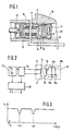
- FIG. 1 shows the outbreak of a workpiece carrier with the information carrier according to the invention in the area of a scanning sensor
- FIG. 2 shows the electrical circuit of the information memory and the scanning sensor with an evaluation circuit
- FIG. 3 shows the impedance of the information carrier measured by the scanning sensor with two resonance points measured over a specific frequency range.
- FIG. 1 the outbreak of such a workpiece carrier of a plurality of workpiece carriers in a production line is shown and designated by 10.
- the workpiece carriers 10 lie on a conveyor belt 11 and serve to hold workpieces that are processed at different stations on the production line.
- the conveyor belt 11 leads the workpiece carriers 10 past various scanning sensors 12, one of which is shown in FIG. 1.
- Each workpiece carrier 10 has an information carrier 13 in which information required for its identification is stored. This information is read out at the various scanning sensors 12 in order to then feed the workpiece picked up in the workpiece carrier 10 to the next work step.
- the information carrier 13 consists essentially of an electrical resonant circuit which contains a transmitter coil 14 with a magnetic circuit which is open at the front and via which the resonant frequency of the resonant circuit can be sensed by the stationary sensors 12.
- the information for identifying the workpiece carrier 10 is thus encoded by tuning the resonant circuit to at least one specific resonance frequency.
- the oscillating circuit is sensed by the scanning sensor 12 via a magnetic field with a sequence of different frequencies.
- the scanning sensor 12 is also provided with a transmitter coil 15 which also contains a magnetic circuit which is open at the front.
- the transmission coil 14 of the mobile workpiece carrier 10 is opposite the transmission coil 15 of the stationary scanning sensor 12.
- the transmitters Coils 14 and 15 are each arranged in a soft magnetic core open at the front, preferably a shell core 16, 17. Behind the shell core 16 of the information carrier 13 there is a printed circuit board 18 which is equipped on one side with capacitors 19 and on the other side with coils 20 and which form lines 21 connected to the transmitter coil 14 to form the electrical resonant circuit.
- the information carrier 13 is embedded in a protective cover 22 which is open at the front and is interchangeably inserted in a bore 23 in the workpiece carrier 10.
- FIG. 2 shows the electrical circuit of the information carrier 13 and the scanning sensor 12 with the evaluation circuit 26 connected to it. From this circuit it can be seen that the resonant circuits in the information carrier 13 consist of two series circuits each of a coil 20a, 20b with a capacitor 19a, 19b, which are connected in parallel to one another and to the transmitter coil 14.
- the leakage inductance of the transmitter coil 14 together with the coils 20a and 20b forms the entire inductance of the resonant circuits in the information carrier 13, but the change in the leakage inductance of the transmitter coil 14 is considerably smaller than the inductance of the coils 20a lying in series with the capacitors 19a, 19b or 20b.
- the leakage inductance of the transmission coil 14 is about 4 mH
- that of the coil 20a is 20 mH
- that of the coil 20b is 4 mH
- the change in the leakage inductance results from different, changing distances between the transmission coils 14 and 15. It is about 1.5 mH.
- the scanning sensor 12 is connected via an impedance measuring stage 24 to a wobble generator 25 which, within a certain frequency range from 10 kHz to 200 kHz, gives a repeated sequence of different frequencies to the transmitter coil 15 of the scanning sensor 12.
- a wobble generator 25 which, within a certain frequency range from 10 kHz to 200 kHz, gives a repeated sequence of different frequencies to the transmitter coil 15 of the scanning sensor 12.
- lower impedance values are measured in the region of the resonance frequencies fo1 and fo2.
- These frequencies of the wobble generator 25 are recorded in an evaluation circuit 26 and, for example, passed on to a central control circuit as a binary number for identification of the workpiece carrier 10.
- the invention is not limited to the exemplary embodiment shown, since the number of resonance elements in the resonant circuit of the information carrier 13 can be limited to one resonance element or can be extended to further additional resonance elements. Likewise, a larger frequency band and thus a larger number of different resonance frequencies can be selected with a sufficient distance from one another in order, if necessary, to obtain further possible combinations.
- resonant circuits however, coding of workpiece carriers, workpieces or other parts can be accommodated in a confined space with a high density of information. The coding can also be carried out separately from the attachment of the transmitter coil by attaching the capacitors.
- the set resonance frequencies on the outside or to provide them with an identification number which corresponds to the binary number read by the scanning sensor 12 and determined in the evaluation circuit 26.
- Such an information carrier is also inexpensive to manufacture, it is simple and robust and largely protected from dirt, moisture and foreign bodies by the protective cover 22. If necessary, it can also be cast in the protective cover 22.
- the protective cover 22 can be pressed in its cylindrical shape into the bore 23, cemented or glued or clamped. In the event of a defect, the information carrier 13 can be replaced quickly and easily.
Landscapes
- Engineering & Computer Science (AREA)
- Artificial Intelligence (AREA)
- Computer Vision & Pattern Recognition (AREA)
- Physics & Mathematics (AREA)
- General Physics & Mathematics (AREA)
- Theoretical Computer Science (AREA)
- General Factory Administration (AREA)
- Geophysics And Detection Of Objects (AREA)
Abstract
Description
Bei bekannten Kodiersystemen von mobilen Teilen, insbesondere von Werkstückträgern oder Werkstücken, die sich zur Weiterverarbeitung, Zusammensetzung oder zum Aussortieren auf einer Fertigungsstraße oder dgl. befinden, werden Informationen zur Kennung des einzelnen Teiles, z.B. des Werkstückträgers aus einem Informationsspeicher herausgelesen, der am Werkstückträger bzw. an dem zu identifizierenden Teil angebracht ist. Die Informationen werden an sogenannten Lesestationen im Bereich der Fertigungsstraße mittels stationär angebrachter Sensoren berührungslos abgetastet.In the case of known coding systems for mobile parts, in particular for workpiece carriers or workpieces, which are located on a production line or the like for further processing, assembly or sorting out, information for identifying the individual part, e.g. of the workpiece carrier is read out from an information memory which is attached to the workpiece carrier or to the part to be identified. The information is scanned contactlessly at so-called reading stations in the area of the production line using stationary sensors.
Für die Identifizierung sind mechanische, optisch lesbare und magnetische Systeme bekannt. Die mechanischen Kodiersysteme (DE-OS 30 12 358) haben den Nachteil, daß sie dem Verschleiß unterworfen sind und daß sie nur eine sehr begrenzte Zahl verschiedener Informationen zulassen, so daß eine individuelle Kennung von mehr als 10 Werkstückträgern auf einem Fließband oder dgl. kaum möglich ist. Außerdem wird ein relativ großer Platz für die mechanische Kodierung benötigt, um beim Lesen der gespeicherten Informationen Fehler zu vermeiden.Mechanical, optically readable and magnetic systems are known for identification. The mechanical coding systems (DE-OS 30 12 358) have the disadvantage that they are subject to wear and that they are only one allow a very limited number of different information, so that an individual identification of more than 10 workpiece carriers on a conveyor belt or the like is hardly possible. In addition, a relatively large space for the mechanical coding is required in order to avoid errors when reading the stored information.
Optisch lesbare Kodiersysteme sind insbesondere für das Verteilen oder Erfassen verpackter Waren bekannt. In einem bestimmten Feld der Verpackung wird eine Vielzahl dicker oder dünner Striche auf der Verpackung angebracht, welche dann durch optische Sensoren ablesbar sind. Solche Systeme haben jedoch den Nachteil, daß sie sehr schmutzempfindlich sind und folglich nur für besondere/saubere Fertigungs-, Sortier- und Verpackungsvorgänge eingesetzt werden können. Bekannte magnetische Kodiersysteme, bei denen die Informationen mit Hilfe starker Magnetfelder auf den Informationsträger, z.B. auf einen magnetisierbaren Sinterwerkstoff oder eine Metallfläche aufgebracht werden, haben den Nachteil, daß sie wegen der magnetischen Streufelder bei berührungsloser Abtastung eine geringe Informationsdichte haben. Bei einer größeren Anzahl von Informationen ist der erforderliche Platz dafür vielfach nicht vorhanden. Außerdem besteht die Gefahr, daß sich Eisenspäne an den magnetisierten Stellen des Informationsträgers festsetzen und das richtige Ablesen der gespeicherten Informationen verhindern.Optically readable coding systems are known in particular for the distribution or detection of packaged goods. A large number of thick or thin lines are applied to the packaging in a specific field of the packaging, which lines can then be read by optical sensors. However, such systems have the disadvantage that they are very sensitive to dirt and consequently can only be used for special / clean manufacturing, sorting and packaging processes. Known magnetic coding systems in which the information is applied to the information carrier, for example to a magnetizable sintered material or a metal surface, using strong magnetic fields have the disadvantage that they have a low information density due to the magnetic stray fields in the case of contactless scanning. With a large amount of information, the space required for this is often not available. There is also the risk that iron filings will stick to the magnetized points on the information carrier and prevent the correct reading of the stored information.
Mit der vorliegenden Lösung wird angestrebt, mit einem möglichst kleinen Informationsträger an mobilen Teilen, Werkstücken oder Werkstückträgern eine Vielzahl von Informationen störungssicher und dauerhaft so einzuspeichern, daß sie in allen Bereichen der Fertigung, der Lagerung, der Verpackung sowie in Versandsystemen durch stationäre Sensoren schnell und zuverlässig auszulesen sind.The aim of the present solution is to store a large amount of information in a fail-safe and permanent manner with the smallest possible information carrier on mobile parts, workpieces or workpiece carriers in such a way that it is used in all areas of production, storage, packaging and in shipping systems can be read quickly and reliably using stationary sensors.
Die erfindungsgemäße Lösung mit den kennzeichnenden Merkmalen des Hauptanspruches hat den Vorteil, daß die Anbringung eines durch die Einstellung des Schwingkreises kodierten Informationsträgers wenig Platz erfordert, und daß die Resonanzfrequenz des Schwingkreises ohne Energiequelle im Informationsträger von einem stationären Sensor abfühlbar ist, indem der Schwingkreis des Informationsträgers als Saugkreis wirkt und die Resonanzfrequenz innerhalb eines vom Sensor abgestrahlten Frequenzbandes durch eine Impedanzänderung am Sensor erfaßt wird. Als weiterer Vorteil ist anzusehen, daß durch eine Vielzahl unterschiedlich eingestellter Schwingkreise eine Vielzahl unterschiedlich kodierter Informationsträger verwendbar ist, so daß damit auch eine Vielzahl von Werkstückträgern, Werkstücken oder anderer Teile auf einer Fertigungsstraße individuell identifiziert werden kann. Dadurch ist es mit dem Kodiersystem möglich, in den Fertigungsstraßen anstelle von Einzelpuffern zwischen verschiedenen Stationen einen Zentralpuffer vorzusehen, aus dem dann jeweils die einzelnen Werkstückträger, Werkstücke oder Teile den richtigen Maschinen zur Weiterverarbeitung zugeführt werden.The solution according to the invention with the characterizing features of the main claim has the advantage that the attachment of an information carrier coded by the setting of the resonant circuit requires little space, and that the resonant frequency of the resonant circuit can be sensed by a stationary sensor without an energy source in the information carrier by the resonant circuit of the information carrier acts as a suction circuit and the resonance frequency is detected within a frequency band emitted by the sensor by an impedance change on the sensor. Another advantage is that a large number of differently coded information carriers can be used due to a large number of differently set resonant circuits, so that a large number of workpiece carriers, workpieces or other parts on a production line can also be individually identified. This makes it possible with the coding system to provide a central buffer in the production lines instead of individual buffers between different stations, from which the individual workpiece carriers, workpieces or parts are then fed to the correct machines for further processing.
Durch die in den Unteransprüchen aufgeführten Maßnahmen sind vorteilhafte Weiterbildungen und Verbesserungen der im Hauptanspruch angegebenen Merkmale möglich. Dabei ist als besonders vorteilhaft anzusehen, den Schwingkreis eines jeden Informationsträgers aus der Übertragungsspule, einem ersten Kondensator und einer weiteren, mit dem Kondensator in Reihe liegenden Spule auszubilden. Dadurch ist es möglich, den Einfluß des Abstandes zwischen der Übertragerspule des Informationsträgers und dem Sensor auf die Resonanzfrequenz des Schwingkreises soweit herabzusetzen, daß auch bei relativ großen Schwankungen des Luftspaltes zwischen den Lesestationen und der Übertragerspule an den mobilen Teilen die Resonanzfrequenzen schnell und zuverlässig ermittelt werden können. Eine besonders große Vielzahl von kodierten Informationen der Informationsspeicher läßt sich dadurch erreichen, daß im Schwingkreis mehrere Reihenschaltungen' aus Spulen und Kondensatoren zueinander und zur Übertragerspule parallel geschaltet sind. Auf diese Weise kann innerhalb eines bestimmten Frequenzbandes der Informationsspeicher auf mehrere Resonanzfrequenzen kodiert und so mit geringem Aufwand am Informationsträger die Anzahl verschiedener Informationen sowie die Anzahl der individuell erkennbaren mobilen Teile nahezu beliebig erhöht werden.Advantageous further developments and improvements of the features specified in the main claim are possible through the measures listed in the subclaims. The resonant circuit of each information carrier from the transmission is to be regarded as particularly advantageous coil, a first capacitor and a further coil in series with the capacitor. This makes it possible to reduce the influence of the distance between the transmitter coil of the information carrier and the sensor on the resonant frequency of the resonant circuit to such an extent that the resonant frequencies can be determined quickly and reliably even with relatively large fluctuations in the air gap between the reading stations and the transmitter coil on the mobile parts can. A particularly large amount of coded information from the information memories can be achieved by connecting a plurality of series circuits comprising coils and capacitors to one another and to the transmitter coil in the resonant circuit. In this way, the information memory can be coded to a plurality of resonance frequencies within a certain frequency band and the number of different pieces of information and the number of individually recognizable mobile parts can be increased almost as desired with little effort on the information carrier.
Ein Ausführungsbeispiel der Erfindung ist in der Zeichnung dargestellt und in der nachfolgenden Beschreibung näher erläutert. Es zeigen Figur 1 den Ausbruch eines Werkstückträgers mit dem erfindungsgemäßen Informationsträger im Bereich eines Abtastsensors, Figur 2 die elektrische Schaltung des Informationsspeichers und des Abtastsensors mit einer Auswerteschaltung und Figur 3 zeigt die vom Abtastsensor gemessene Impedanz des Informationsträgers mit zwei über einen bestimmten Frequenzbereich gemessenen Resonanzstellen.An embodiment of the invention is shown in the drawing and explained in more detail in the following description. FIG. 1 shows the outbreak of a workpiece carrier with the information carrier according to the invention in the area of a scanning sensor, FIG. 2 shows the electrical circuit of the information memory and the scanning sensor with an evaluation circuit, and FIG. 3 shows the impedance of the information carrier measured by the scanning sensor with two resonance points measured over a specific frequency range.
In Figur 1 ist von einer Vielzahl von Werkstückträgern einer Fertigungsstraße der Ausbruch eines solchen Werkstückträgers dargestellt und mit 10 bezeichnet. Die Werkstückträger 10 liegen auf einem Transportband 11 und dienen zur Aufnahme von Werkstücken, die an verschiedenen Stationen der Fertigungsstraße bearbeitet werden. Das Transportband 11 führt dabei die Werkstückträger 10 an verschiedene Abtastsensoren 12 vorbei, von denen einer in Figur 1 dargestellt ist. Jeder Werkstückträger 10 hat einen Informationsträger 13, in dem eine zu seiner Identifizierung benötigte Information eingespeichert ist. An den verschiedenen Abtastsensoren 12 werden diese Informationen ausgelesen, um anschließend das im Werkstückträger 10 aufgenommene Werkstück dem nächsten Arbeitsgang zuzuführen. Der Informationsträger 13 besteht im wesentlichen aus einem elektrischen Schwingkreis, der eine Übertragerspule 14 mit einem vorn offenen Magnetkreis enthält, über den die Resonanzfrequenz des Schwingkreises von den stationären Sensoren 12 abzufühlen ist. Die Kodierung der Information zur Identifizierung des Werkstückträgers 10 erfolgt somit durch die Abstimmung des Schwingkreises auf mindestens eine bestimmte Resonanzfrequenz. Zur Ermittlung der Resonanzfrequenz wird der Schwingkreis von dem Abtastsensor 12 über ein Magnetfeld mit einer Folge unterschiedlicher Frequenzen abgefühlt. Zu diesem Zweck ist auch der Abtastsensor 12 mit einer Übertragerspule 15 versehen, die ebenfalls einen vorn offenen Magnetkreis enthält. Beim Abfühlen der Information des mobilen Werkstückträgers 10 liegt die Übertragungsspule 14 des mobilen Werkstückträgers 10 der Übertragungsspule 15 des stationären Abtastsensors 12 gegenüber. Die Übertragerspulen 14 und 15 sind dabei jeweils in einem vorn offenen weichmagnetischen Kern, vorzugsweise einem Schalenkern 16, 17 angeordnet. Hinter dem Schalenkern 16 des Informationsträgers 13 befindet sich eine Leiterplatte 18, die auf ihrer einen Seite mit Kondensatoren 19 und auf ihrer anderen Seite mit Spulen 20 bestückt ist und die über Leitungen 21 mit der Übertragerspule 14 verbunden den elektrischen Schwingkreis bilden. Der Informationsträger 13 ist in einer vorn offenen Schutzhülle 22 eingebettet und in einer Bohrung 23 im Werkstückträger 10 auswechselbar eingesetzt.In FIG. 1, the outbreak of such a workpiece carrier of a plurality of workpiece carriers in a production line is shown and designated by 10. The
Figur 2 zeigt die elektrische Schaltung des Informationsträgers 13 und des Abtastsensors 12 mit der daran angeschlossenen Auswerteschaltung 26. Aus dieser Schaltung ist erkennbar, daß die Schwingkreise im Informationsträger 13 aus zwei Reihenschaltungen von je einer Spule 20a, 20b mit einem Kondensator 19a, 19b besteht, die zueinander und zur Übertragerspule 14 parallel geschaltet sind. Die Streuinduktivität der Übertragerspule 14 bildet dabei zusammen mit den Spulen 20a und 20b die gesamte Induktivität der Schwingkreise im Informationsträgers 13, wobei jedoch die Änderung der Streuinduktivität der Übertragerspule 14 wesentlich kleiner ist als die Induktivität der mit den Kondensatoren 19a, 19b in Reihe liegenden Spulen 20a bzw. 20b. Im Beispielsfall beträgt die Streuinduktivität der Übertragerspule 14 etwa 4 mH, die der Spule 20a beträgt 20 mH und die der Spule 20b beträgt 4 mH, die Änderung der Streuinduktivität ergibt sich aus unterschiedlichen, sich verändernden Abständen zwischen den Übertragungsspulen 14 und 15. Sie beträgt etwa 1,5 mH. Durch Auswahl der beiden Kondensatoren 19a und 19b ist der Schwingkreis des Informationsträgers 10 auf zwei verschiedene Resonanzfrequenzen eingestellt, die sich aus der Formel ergeben:![]()
![]()
Daraus ergeben sich bei einer Kapazität des Kondensators 19a von 2 nF und für den Kondensator 19b von 100 pF jeweils zwei verschiedene Resonanzfrequenzen mit fo1 von 22 kHz und fo2 = 178 kHz.With a capacitance of the
Der Abtastsensor 12 ist über eine Impedanzmeßstufe 24 an einen Wobbelgenerator 25 angeschlossen, der innerhalb eines bestimmten Frequenzbereiches von 10 kHz bis 200 kHz eine wiederholte Folge unterschiedlicher Frequenzen auf die Übertragerspule 15 des Abtastsensors 12 gibt. Sobald der Informationsträger 13 im Werkstückträger 10 dem Abtastsensor 12 gegenüberliegt, werden - wie Figur 3 zeigt - im Bereich der Resonanzfrequenzen fo1 und fo2 geringere Impedanzwerte gemessen. In einer Auswerteschaltung 26 werden diese Frequenzen des Wobbelgenerators 25 erfaßt und beispielsweise als Binärzahl zur Identifizierung des Werkstückträgers 10 in eine zentrale Steuerschaltung weitergegeben.The
Werden bei einer entsprechenden Stufung im Frequenzband 20 mögliche Resonanzfrequenzen mit beispielsweise einem Abstand von 16 % durch entsprechende Wahl der Kondensatoren 19a und 19b sowie der Spulen 20a und 20b realisiert, so ergeben sich nach der Kombinationslehre
Die Erfindung ist nicht auf das dargestellte Ausführungsbeispiel beschränkt, da die Anzahl der Resonanzglieder im Schwingkreis des Informationsträgers 13 auf ein Resonanzglied beschränkt oder auf weitere zusätzliche Resonanzglieder erweitert werden kann. Ebenso kann ein größeres Frequenzband und somit eine größere Anzahl verschiedener Resonanzfrequenzen mit ausreichendem Abstand voneinander gewählt werden, um gegebenenfalls noch weitere Kombinationsmöglichkeiten zu erlangen. Durch die Verwendung von Schwingkreisen läßt sich jedoch eine Kodierung von Werkstückträgern, von Werkstücken oder anderen Teilen auf engstem Raume mit hoher Informationsdichte unterbringen. Dabei kann die Kodierung durch Anbringung der Kondensatoren auch getrennt von der Anbringung der Übertragerspule erfolgen. Zur besseren Kennung der einzelnen Informationsträger ist es außerdem möglich, die eingestellten Resonanzfrequenzen außen aufzudrucken bzw. sie mit einer Kennzahl zu versehen, die der vom Abtastsensor 12 ausgelesenen, in der Auswerteschaltung 26 ermittelten binären Zahl entspricht. Ein solcher Informationsträger ist außerdem preisgünstig herstellbar, er ist einfach und robust aufgebaut und durch die Schutzhülle 22 vor Schmutz, Feuchtigkeit und Fremdkörper weitgehend geschützt. Er kann in der Schutzhülle 22 gegebenenfalls auch vergossen werden. Die Schutzhülle 22 läßt sich in ihrer zylinderischen Form in die Bohrung 23 einpressen, einkitten oder festkleben bzw. festspannen. Bei einem Defekt kann dadurch der Informationsträger 13 einfach und schnell ausgewechselt werden.The invention is not limited to the exemplary embodiment shown, since the number of resonance elements in the resonant circuit of the
Da die Änderung der Streuinduktivität der beiden Übertragerspulen 14 und 15 gegenüber der Induktivität der Spulen 20a bzw. 20b klein ist, sind relativ große Toleranzen in dem Spalt zwischen Informationsträger 13 und Abtastsensor 12 möglich, so daß ein solches Kodiersystem auch bei Fertigungsstraßen in der Schwerindustrie anwendbar ist. Durch eine entsprechende Einstellung des Wobbelgenerators 25 ist es ferner möglich, den Durchlauf des Frequenzbandes soweit zu erhöhen, daß die Informationen im Informationsträger 13 in sehr kurzer Zeit zuverlässig ausgelesen werden können. Die abtastenden Sensoren können dann auch bei höheren Geschwindigkeiten des Transportbandes 11 die Informationen beim Durchlauf des Informationsträgers 13 auslesen.Since the change in the leakage inductance of the two
Claims (8)
Applications Claiming Priority (2)
| Application Number | Priority Date | Filing Date | Title |
|---|---|---|---|
| DE19823242764 DE3242764A1 (en) | 1982-11-19 | 1982-11-19 | CODING SYSTEM FOR DETECTING INFORMATION ON MOBILE WORKPIECE CARRIERS AND THE LIKE |
| DE3242764 | 1982-11-19 |
Publications (2)
| Publication Number | Publication Date |
|---|---|
| EP0111693A2 true EP0111693A2 (en) | 1984-06-27 |
| EP0111693A3 EP0111693A3 (en) | 1987-03-25 |
Family
ID=6178480
Family Applications (1)
| Application Number | Title | Priority Date | Filing Date |
|---|---|---|---|
| EP83110734A Withdrawn EP0111693A3 (en) | 1982-11-19 | 1983-10-27 | Coding system for retrieving information from moving work piece carriers |
Country Status (2)
| Country | Link |
|---|---|
| EP (1) | EP0111693A3 (en) |
| DE (1) | DE3242764A1 (en) |
Cited By (10)
| Publication number | Priority date | Publication date | Assignee | Title |
|---|---|---|---|---|
| DE3541676A1 (en) * | 1985-11-26 | 1987-05-27 | Euchner & Co | IDENTIFICATION SYSTEM |
| EP0285188A1 (en) * | 1987-02-16 | 1988-10-05 | N.V. Nederlandsche Apparatenfabriek NEDAP | A method of placing an electronic responder in or near an electrically conductive article, as well as an electrically conductive article provided with an electronic responder |
| US4809426A (en) * | 1985-11-20 | 1989-03-07 | Tokyo Keiki Company, Ltd. | Information processing apparatus of tool holder |
| US4856177A (en) * | 1987-02-10 | 1989-08-15 | Tokyo Keiki Company Ltd. | Automatic tool changer with electromagnetically readable tool holder having an electromagnetically coupling stopper for numerical control |
| EP0389406A2 (en) * | 1989-03-24 | 1990-09-26 | The Goodyear Tire & Rubber Company | Integrated circuit transponder in a pneumatic tire for tire identification |
| WO1992003876A1 (en) * | 1990-08-15 | 1992-03-05 | Vaseal Electronics Limited | A combination of a proximity switch and a target, a proximity switch and a target for such a combination |
| US5357076A (en) * | 1991-04-12 | 1994-10-18 | The Lincoln Electric Company | Plasma torch with identification circuit |
| DE19910935A1 (en) * | 1999-03-12 | 2000-09-21 | Guenter Lang | Label carrier for tools in NC milling and drilling machines, is attached to tool holder |
| DE10347591A1 (en) * | 2003-10-14 | 2005-06-02 | Klie, Jürgen, Dr.-Ing. | Measurement and test arrangement identification system converts bit sequence read out of memory into test arrangement-specific identity number uniquely associated with corresponding bit sequence in table stored in data processing unit |
| CN110404815A (en) * | 2019-07-12 | 2019-11-05 | 浙江楠源机械制造有限公司 | Utilize the automobile parts processing method of vertical lathe |
Families Citing this family (5)
| Publication number | Priority date | Publication date | Assignee | Title |
|---|---|---|---|---|
| DE3607771C3 (en) * | 1986-03-08 | 1996-09-26 | Rolf Hermle | Tool holder with data carrier |
| DE3734290A1 (en) * | 1987-10-09 | 1989-04-27 | Rexroth Bernd Gmbh & Co | Reading device for identity cards |
| DE3813492C2 (en) * | 1988-04-22 | 1993-12-23 | Euchner & Co | Programmable device for the coded storage of at least one destination for transport systems with destination control |
| DE19631425A1 (en) * | 1996-08-06 | 1998-02-12 | Wolf & Beck Gmbh Dr | Identification method for interchangeable accessories of machines tools |
| DE202007002838U1 (en) * | 2007-02-27 | 2008-07-03 | Robert Bosch Gmbh | Workpiece identification system |
Citations (2)
| Publication number | Priority date | Publication date | Assignee | Title |
|---|---|---|---|---|
| GB1199256A (en) * | 1966-10-06 | 1970-07-22 | Donovan Electrical Company Ltd | Safety Device Primarily for Machine Guards |
| US3752960A (en) * | 1971-12-27 | 1973-08-14 | C Walton | Electronic identification & recognition system |
-
1982
- 1982-11-19 DE DE19823242764 patent/DE3242764A1/en not_active Withdrawn
-
1983
- 1983-10-27 EP EP83110734A patent/EP0111693A3/en not_active Withdrawn
Patent Citations (2)
| Publication number | Priority date | Publication date | Assignee | Title |
|---|---|---|---|---|
| GB1199256A (en) * | 1966-10-06 | 1970-07-22 | Donovan Electrical Company Ltd | Safety Device Primarily for Machine Guards |
| US3752960A (en) * | 1971-12-27 | 1973-08-14 | C Walton | Electronic identification & recognition system |
Cited By (16)
| Publication number | Priority date | Publication date | Assignee | Title |
|---|---|---|---|---|
| US4809426A (en) * | 1985-11-20 | 1989-03-07 | Tokyo Keiki Company, Ltd. | Information processing apparatus of tool holder |
| DE3541676A1 (en) * | 1985-11-26 | 1987-05-27 | Euchner & Co | IDENTIFICATION SYSTEM |
| EP0224226A2 (en) * | 1985-11-26 | 1987-06-03 | Euchner & Co. | Identification system |
| US4720907A (en) * | 1985-11-26 | 1988-01-26 | Euchner & Co. | Identification system |
| EP0224226A3 (en) * | 1985-11-26 | 1988-02-03 | Euchner & Co. | Identification system |
| US4856177A (en) * | 1987-02-10 | 1989-08-15 | Tokyo Keiki Company Ltd. | Automatic tool changer with electromagnetically readable tool holder having an electromagnetically coupling stopper for numerical control |
| EP0285188A1 (en) * | 1987-02-16 | 1988-10-05 | N.V. Nederlandsche Apparatenfabriek NEDAP | A method of placing an electronic responder in or near an electrically conductive article, as well as an electrically conductive article provided with an electronic responder |
| EP0389406A3 (en) * | 1989-03-24 | 1990-11-28 | The Goodyear Tire & Rubber Company | Integrated circuit transponder in a pneumatic tire for tire identification |
| EP0389406A2 (en) * | 1989-03-24 | 1990-09-26 | The Goodyear Tire & Rubber Company | Integrated circuit transponder in a pneumatic tire for tire identification |
| WO1992003876A1 (en) * | 1990-08-15 | 1992-03-05 | Vaseal Electronics Limited | A combination of a proximity switch and a target, a proximity switch and a target for such a combination |
| US5291152A (en) * | 1990-08-15 | 1994-03-01 | Vaseal Electronics Limited | Proximity switch having oscillator inductively coupled through pulsed Faraday shield to resonant target |
| US5357076A (en) * | 1991-04-12 | 1994-10-18 | The Lincoln Electric Company | Plasma torch with identification circuit |
| DE19910935A1 (en) * | 1999-03-12 | 2000-09-21 | Guenter Lang | Label carrier for tools in NC milling and drilling machines, is attached to tool holder |
| DE10347591A1 (en) * | 2003-10-14 | 2005-06-02 | Klie, Jürgen, Dr.-Ing. | Measurement and test arrangement identification system converts bit sequence read out of memory into test arrangement-specific identity number uniquely associated with corresponding bit sequence in table stored in data processing unit |
| DE10347591B4 (en) * | 2003-10-14 | 2006-04-06 | Klie, Jürgen, Dr.-Ing. | Measuring and test equipment identification arrangement |
| CN110404815A (en) * | 2019-07-12 | 2019-11-05 | 浙江楠源机械制造有限公司 | Utilize the automobile parts processing method of vertical lathe |
Also Published As
| Publication number | Publication date |
|---|---|
| DE3242764A1 (en) | 1984-05-24 |
| EP0111693A3 (en) | 1987-03-25 |
Similar Documents
| Publication | Publication Date | Title |
|---|---|---|
| EP0111693A2 (en) | Coding system for retrieving information from moving work piece carriers | |
| DE2912712C2 (en) | ||
| DE3038614C2 (en) | ||
| DE60014708T2 (en) | ANTENNA FOR RADIO FREQUENCIES FOR AN OBJECT CHECKER WITH A RADIO FREQUENCY ANTENNA AND AN ASSEMBLED ELECTRICAL CIRCUIT | |
| DE3732367A1 (en) | Method and apparatus for the preparation of a subsequent treatment operation on a textile bobbin | |
| DE60221304T2 (en) | Antenna for card reader | |
| DE10056148A1 (en) | Contactless data medium has data processing unit and at least two reception antennas for each different transmission region, whereby at least two of the antennas form a unit | |
| DE202005021690U1 (en) | Resonance etiquette on a disk provided with a metallization | |
| EP1078138A1 (en) | Mobile transponder for a motor vehicle | |
| EP0784829B1 (en) | Support arrangement to be embedded into a contactless chip card | |
| DE60125975T2 (en) | ANTENNA WITH REDUCED MAGNETIC REMOTE FIELD FOR THE ACTIVATION AND DEACTIVATION OF EAS MARKERS | |
| DE112015004527T5 (en) | Image reading device | |
| DE102004025663B4 (en) | Procedure and system for completeness check in one package | |
| DE3203897C2 (en) | ||
| EP3743846B1 (en) | Device and method for coding hf transponders | |
| DE4100222C2 (en) | ||
| DE10148919A1 (en) | Method and device for locating moving objects | |
| EP0194630A2 (en) | Method for optically identifying and/or locating an object | |
| DE602005003990T2 (en) | RF transponder and frequency tuning method | |
| DE19911032C5 (en) | Gas bottle valve protection device with transponder unit | |
| DE19512921A1 (en) | Checking process for security documents such as banknotes | |
| AT398497B (en) | CODING SYSTEM AND CODE CARRIER | |
| DE4427000A1 (en) | Method and device for high-speed measurement and marking of magnetic materials | |
| DE3516214A1 (en) | Apparatus for testing the hardness of iron parts | |
| DE2347393C2 (en) | Method and device for recognizing a digital code |
Legal Events
| Date | Code | Title | Description |
|---|---|---|---|
| PUAI | Public reference made under article 153(3) epc to a published international application that has entered the european phase |
Free format text: ORIGINAL CODE: 0009012 |
|
| 17P | Request for examination filed |
Effective date: 19831027 |
|
| AK | Designated contracting states |
Designated state(s): CH DE FR GB IT LI NL |
|
| PUAL | Search report despatched |
Free format text: ORIGINAL CODE: 0009013 |
|
| STAA | Information on the status of an ep patent application or granted ep patent |
Free format text: STATUS: THE APPLICATION HAS BEEN WITHDRAWN |
|
| AK | Designated contracting states |
Kind code of ref document: A3 Designated state(s): CH DE FR GB IT LI NL |
|
| 18W | Application withdrawn |
Withdrawal date: 19870211 |
|
| RIN1 | Information on inventor provided before grant (corrected) |
Inventor name: SCHIRMER, GUENTER Inventor name: HESSER, PAUL Inventor name: FAUSER, EDWIN, DIPL.-ING. |