EP0109920B1 - Process for cleaning holes in printed circuit boards with permanganate and basic solutions - Google Patents
Process for cleaning holes in printed circuit boards with permanganate and basic solutions Download PDFInfo
- Publication number
- EP0109920B1 EP0109920B1 EP83730109A EP83730109A EP0109920B1 EP 0109920 B1 EP0109920 B1 EP 0109920B1 EP 83730109 A EP83730109 A EP 83730109A EP 83730109 A EP83730109 A EP 83730109A EP 0109920 B1 EP0109920 B1 EP 0109920B1
- Authority
- EP
- European Patent Office
- Prior art keywords
- solution
- resin
- permanganate
- copper
- treatment
- Prior art date
- Legal status (The legal status is an assumption and is not a legal conclusion. Google has not performed a legal analysis and makes no representation as to the accuracy of the status listed.)
- Expired
Links
Images

Classifications
-
- H—ELECTRICITY
- H05—ELECTRIC TECHNIQUES NOT OTHERWISE PROVIDED FOR
- H05K—PRINTED CIRCUITS; CASINGS OR CONSTRUCTIONAL DETAILS OF ELECTRIC APPARATUS; MANUFACTURE OF ASSEMBLAGES OF ELECTRICAL COMPONENTS
- H05K3/00—Apparatus or processes for manufacturing printed circuits
- H05K3/0011—Working of insulating substrates or insulating layers
- H05K3/0055—After-treatment, e.g. cleaning or desmearing of holes
-
- H—ELECTRICITY
- H05—ELECTRIC TECHNIQUES NOT OTHERWISE PROVIDED FOR
- H05K—PRINTED CIRCUITS; CASINGS OR CONSTRUCTIONAL DETAILS OF ELECTRIC APPARATUS; MANUFACTURE OF ASSEMBLAGES OF ELECTRICAL COMPONENTS
- H05K2203/00—Indexing scheme relating to apparatus or processes for manufacturing printed circuits covered by H05K3/00
- H05K2203/07—Treatments involving liquids, e.g. plating, rinsing
- H05K2203/0779—Treatments involving liquids, e.g. plating, rinsing characterised by the specific liquids involved
- H05K2203/0786—Using an aqueous solution, e.g. for cleaning or during drilling of holes
- H05K2203/0793—Aqueous alkaline solution, e.g. for cleaning or etching
-
- H—ELECTRICITY
- H05—ELECTRIC TECHNIQUES NOT OTHERWISE PROVIDED FOR
- H05K—PRINTED CIRCUITS; CASINGS OR CONSTRUCTIONAL DETAILS OF ELECTRIC APPARATUS; MANUFACTURE OF ASSEMBLAGES OF ELECTRICAL COMPONENTS
- H05K2203/00—Indexing scheme relating to apparatus or processes for manufacturing printed circuits covered by H05K3/00
- H05K2203/07—Treatments involving liquids, e.g. plating, rinsing
- H05K2203/0779—Treatments involving liquids, e.g. plating, rinsing characterised by the specific liquids involved
- H05K2203/0786—Using an aqueous solution, e.g. for cleaning or during drilling of holes
- H05K2203/0796—Oxidant in aqueous solution, e.g. permanganate
Definitions
- the present invention relates to a method for preparing the synthetic resin-containing surface of a workpiece for the subsequent metallization according to the preamble of claim 1.
- such resin smearings have no disruptive influence; for others, however, it is of the utmost importance to remove them, such as in the manufacture of multilevel circuits, i. i.e., circuit boards which have a series of parallel conductor planes inside, which are connected to each other at predetermined points by holes made perpendicular to them.
- the hole walls are coated with metal in a known manner; however, a conductive connection only occurs if the resin smearings have been removed from the parts of the perforated wall, the metallic surfaces of which are formed by cutting through the conductor tracks.
- connection of two or more circuit levels through holes with metallized walls is also used for automatically routed wire circuits, the so-called MULTIWIRERTM circuits.
- MULTIWIRERTM circuits The connection of two or more circuit levels through holes with metallized walls is also used for automatically routed wire circuits, the so-called MULTIWIRERTM circuits.
- conductor tracks made of wire are laid on or in the plate surface, and the conductive connections between two or more levels of these wire circuits are made through holes with metallized walls.
- the holes are made at the points designated as connection positions and cut through the wires of the conductor tracks, so that the end faces of the wire form part of the inner wall of the hole.
- resin-dissolving chemicals are used to remove resin residues and smears, such as.
- B. conc. Sulfuric acid with which a layer of 0.025 mm thick resin, as is usually the maximum, can be removed within one minute.
- sulfuric acid (92 to 98%) requires extraordinary precautionary measures on the part of the operating personnel and additionally leads to an undesirable roughening of the inner walls of the hole.
- Another disadvantage is that conc. Sulfuric acid is highly hygroscopic, so that the required exposure time changes over time due to water absorption and the acid eventually becomes ineffective and must be replaced.
- Concentrated chromic acid can also be used to remove resin residues and smears, with an exposure time of 5 to 15 minutes. The operator must also take special precautions when using this procedure. In addition, a special lining of both the dip tank for the chromic acid and the casing of the plate holders is necessary. Increasingly stringent wastewater regulations and the difficulty in destroying chromic acid residues in an ecologically harmless way are further considerations that speak against this process. In addition, chrome residues on the treated surfaces have a negative effect on the electroless metal deposition on them. For elimination Resin smearings and residues in holes produced mechanically or by laser are also proposed to use permanganate solutions (DE-PS-2 550 598).
- An alkaline permanganate solution with a pH of at least 13 is used there.
- Such permanganate solutions are used in the manufacture of Multiwire RTM circuit boards to remove smeared epoxy from the wire tips and to etch off the polyimide insulation from the wire ends.
- the subsequent electroless metal deposition did not result in uniform metal layers, but rather point holes and uncoated areas occurred.
- treatment with a permanganate solution should not only remove the resin residues resulting from drilling the holes; the polyimide insulation of the wires should also be etched away from the interfaces which form part of the inner walls of the hole.
- a neutralization treatment with SnCl 2 , formaldehyde or hydrazine hydrate solutions is carried out and the holes are rinsed.
- the permanganate treatment significantly reduces the activity of the base material which has already been catalytically activated for electroless metal deposition, so that two different metal plating baths must be used in succession in the subsequent electroless copper plating: First, a copper plating bath is used which has a sufficiently high activity to effect the deposition of a first copper layer; a modified composition bath is then used which is less active and sufficiently stable to obtain a deposition layer of the desired thickness and quality. The formation of the first deposition layer takes place slowly, and the time required cannot be estimated in advance. The change from one deposition bath to another is generally made on the basis of the appearance of the first metal layer, which often leads to difficulties in controlling the bath operation. The two deposition baths cannot be operated continuously either.
- Multi-level circuits are usually produced by known methods in which the hole walls for the electroless metal deposition are sensitized by means of catalytically active activation solutions.
- point holes and uncoated areas occur in the electrolessly deposited metal layers when using permanent magnet solutions with a high pH value for hole cleaning.
- the plates have to be sensitized again or all steps of the electroless copper plating have to be repeated. If the permanganate treatment is not neutralized, a highly active permanganate residue remains on the surface of the base material, which causes copper particles to precipitate out of the electroless copper plating bath and ultimately destroy the bath.
- the object of the present invention is to provide an improved method for preparing the synthetic resin-containing surfaces for removing resin residues and smearings on their hole walls and an improvement in the adhesive strength on synthetic resin-containing surfaces without undesired residues remaining on the surface.
- the process for the production of MultiwireRTM or multilevel circuits is to be improved in particular in such a way that the reliability of the metal deposition process is increased and uninterrupted operation of the deposition bath is achieved, and the removal of resin residues and smearings on perforated walls in synthetic resin-containing materials is facilitated, while improving the adhesive strength of electrolessly deposited metal layers on the outer surfaces of the base material.
- the process according to the invention is characterized in that the surface is treated with an alkaline solution at a temperature between 30 ° C and 95 ° C and for a period of time sufficient to remove all manganese residues.
- the present invention is based on the finding that there is a connection between manganese-containing residues on the surface of the base material and the quality of the subsequently deposited metal layer.
- the surface of the base material can be extracted with aqua regia and the extract can then be examined by atomic absorption spectroscopy (AAS). Large amounts of manganese residues were found when using basic Permanganate solutions with a pH of more than 13. All stated pH values were determined at 25 ° C. If these residues were not neutralized, a subsequent metal deposition proceeded quickly, but with spontaneous decomposition of the deposition bath. The interposition of a neutralization step had the result that holes formed in the subsequently electrolessly deposited metal layer due to the residues remaining on the surface.
- AAS atomic absorption spectroscopy
- treatment with an alkali hydroxide solution further reduced the amount of manganese-containing residues, so that no noticeable residues of this type remained on the surface and the conditions for the deposition of an essentially or completely hole-free and defect-free metal layer were met.
- Treatment with the alkali hydroxide solution also helps to remove resin smears and resinous residues as well as polyimide resins.
- a base material plate 10 made of epoxy glass fabric carries an adhesion promoter layer 12 on both sides.
- the wires of the circuit pattern 13 are laid in the adhesion promoter layers 12 and provided with polyimide insulation (14).
- a film of epoxy glass fabric 15 is pressed onto the top and bottom using heat and pressure with the plate.
- a polyethylene film 16 applied with a pressure sensitive adhesive represents a removable mask during the subsequent metal deposition.
- a hole 17 is drilled in the MultiwireRTM plate, which has the resin smear 18.
- Fig. 3 shows a section through the plate after the polyethylene film 16 has shrunk by the action of heat so far that the edge of the hole 17 is no longer covered by this.
- Treatment with an alkaline permanganate solution has also been carried out to remove the resin smearings 18.
- the manganese-containing residues on the surface and the polyimide insulation 14 of the conductor wire were removed at 19 by treatment with an alkali hydroxide solution.
- Any metal permanganate can be used as long as it is stable in aqueous solutions and soluble to at least 10 g / l.
- alkali and alkaline earth permanganates are preferred, the use of sodium and potassium permanganate being particularly advantageous since these can be obtained easily and at a comparatively low price and have good water solubility.
- the permanganate content of the solution can be varied within wide limits, for example from 10 g / l to the saturation concentration.
- concentrations between 10 and 60 g / l prove to be particularly suitable, since the rate at which the binding centers form increases up to a value of approximately 60 g / l.
- concentrations lower than 10 g / l are used, the binding centers form too slowly for such low concentrations to be of technical interest.
- the pH of the permanganate solution normally drops over time due to CO 2 absorption from the air, for example from 12.5 to 11.5, which makes it necessary to add KOH to the solution.
- oxidation-insensitive wetting agents such as fluorinated hydrocarbons, can be added to the solution.
- Usual exposure times are in the Range from 5 minutes to over two hours at temperatures between 35 and 100 ° C. The best results were achieved at temperatures between 40 ° C and 80 ° C and exposure times between 5 and 75 minutes.
- the treatment can be carried out by dipping or spraying or in another way known for the treatment of synthetic resin-containing surfaces.
- a «body with synthetic resin-containing surfaces is one which - for. B. cast in molds, laminated, resin-coated etc. - consists entirely of resin or at least has a resin-containing surface.
- the base materials described in DE-PS-1 665 314, which have a surface with an adhesive layer containing synthetic resin and in which uniformly finely divided particles of oxidizable and degradable natural or synthetic rubber are embedded, can be treated.
- the proportions of the solution components must be selected so that the best possible etching result is achieved.
- resin smears that occur when drilling holes in Multiwire RTM boards do not have a uniform composition, since the insulating layer of the wire is made of polyimide, while the laminated base material can be made of, for example, an epoxy glass laminate; the resinous adhesive layer likewise applied to the base material can in turn have a different composition. It is therefore quite possible that the resin smear can be a mixture of the three components mentioned.
- resin residues and smears should be removed within 5-75 minutes, with contact times between 20 and 40 minutes being preferred. If a longer treatment is required to completely remove resin residues, it is advisable to remove the multilevel or MultiwireRTM plate from the permanganate solution after 20 to 45 minutes, to add it to the neutralizing solution, to rinse it and then to rinse it again in the solution containing permanganate dive. This procedure is believed to produce less manganese residues that slow down resin smear removal. The rate at which the resin layer is removed is proportional to the permanganate concentration, but the amount of manganese residues increases with it. Concentrations in the range from 45 to 60 g / l of potassium permanganate are therefore preferred.
- the rate of resin removal is also directly proportional to the temperature of the treatment solution, with temperatures between 40 and 80 ° C giving satisfactory results; a temperature of 60 ° C. is preferred. If resin removal baths according to the present invention are operated at temperatures significantly lower than 40 ° C., the removal of the resin smear slows down considerably and difficulties arise in maintaining the permanganate concentration. Temperatures significantly higher than 60 ° C offer no noticeable advantage, i. H. there is no significant increase in the etching rate.
- Results are achieved when the pH of the alkaline permanganate solution is set to values between 11 and 13, a pH of 12.5 having proven particularly advantageous.
- Sodium or potassium hydroxide is preferably used to regulate the pH.
- the results of the treatment can be improved if the solution contains small amounts of a wetting agent, e.g. B. a fluorinated hydrocarbon; a potassium fluoroalkyl carboxylate, an anionic surfactant, is preferably used, for example.
- a wetting agent e.g. B. a fluorinated hydrocarbon; a potassium fluoroalkyl carboxylate, an anionic surfactant, is preferably used, for example.
- the procedure according to the invention consists in having the treatment with the permanganate solution followed by the treatment with a neutralizing agent in order to neutralize permanganate remaining on the surface before the catalysis and metal deposition.
- This neutralization step appears to promote the removal of excess permanganate from resinous surfaces and prevents dilution of the bath solutions subsequently used, as well as other troublesome effects due to the presence of a strong oxidizing agent in the subsequent process steps.
- Tin (II) ions are suitable as neutralizers, such as those in an acidified tin (II) chloride solution such as SnCl 2 . HCI is present. Also suitable are bisulfite ions, hydroxylamine hydrochloride, hydrochloric acid, formaldehyde, sugar and in principle any water-soluble compound that can be oxidized by permanganate.
- the object treated with the permanganate solution is briefly immersed in an aqueous solution which contains the neutralizing agent, for example in concentrations between 2 and 100 g / l, and then rinsed thoroughly with water before being subjected to the next process step.
- the neutralizing agent for example in concentrations between 2 and 100 g / l
- Further suitable neutralizers are described in DE-PS-2 550 597.
- the method according to the invention includes an etching process using a hot solution of a base, usually an alkali or tetraalkylammonium hydroxide.
- a base usually an alkali or tetraalkylammonium hydroxide.
- concentration of the hydroxide used can be varied within wide limits, for example from 0.5 to 20 mol / l.
- the basic solution of the hydroxide used in each case can contain a complexing agent for manganese, for example ethylene diaminotetraacetate (EDTA), a tartrate, etc., where this appears desirable.
- EDTA ethylene diaminotetraacetate
- Conventional wetting agents can also be added to the solution.
- the required exposure time depends on the hydroxide concentration and the temperature of the treatment solution and can be, for example, between 2 and 60 minutes and preferably between 10 and 30 minutes at temperatures between 40 and 95 ° C.
- a solution of 19 mol / l sodium hydroxide at a temperature of approx. 95 ° C has proven to be particularly effective for removing residues containing manganese.
- lower temperatures of approximately 60 ° C. and lower concentrations of approximately 4 mol / l are preferred.
- the two-stage etching treatment with a permanganate and a hydroxide solution at a pH below 13 results in a better controllability of the process in the production of Multiwire RTM plates than when only one etching step is used at a pH above 13.
- the polyimide insulation is removed in a separate etching step using a solution which does not contain permanganate and whose hydroxide content can therefore be determined by means of a simple acid-base titration.
- the lower pH value of the permanganate solution compared to the one-step process can be measured with a pH electrode and checked with sufficient accuracy to keep it at approx. 12.5.
- the surface of a resinous material can be activated for electroless metal deposition by the material itself containing a catalyst, for example a palladium compound or copper oxide. If materials are used which do not contain such an additive as catalyst, then, as is known to the person skilled in the art with electroless metal deposition, the steps according to the invention for removing resin residues from the hole walls, for promoting the activity of the surfaces, must be followed by treatment with a catalyst to sensitize the preactivated surfaces to electroless metal plating before contacting the metal plating bath. A number of methods are known for surface sensitization or catalysis. Electroless metal is then deposited on the body activated in this way and, if necessary, treated with a catalyst, such as. B. a nickel layer from a known nickel hypophosphite bath. Instead of nickel, copper can also be deposited on the surface from a conventional electroless copper plating bath.
- a catalyst for example a palladium compound or copper oxide.
- the method according to the invention has a large number of advantages with regard to the control of the method parameters. Because of the comparatively low pH value of the permanganate solution, it is possible to determine it precisely with a conventional pH electrode and to keep it constant in the usual way.
- the permanganate concentration can be determined spectrophotometrically at a wavelength of 525 nm or by potentiometric titration.
- the hydroxide solution of the second etching step according to the invention can be checked by means of acid-base titration; however, very precise monitoring of the hydroxide concentration is not necessary.
- circuit boards are attached vertically in a rack which is moved about 15 to 20 times a minute by 5 to 7.5 cm in the horizontal direction.
- Multiwire RTM plates were produced using the described method.
- a glass fiber fabric was impregnated with epoxy resin, which contains catalytic filling material (DE-PS-1 696 604), and provided on both sides with a 0.1 mm thick, catalytically activatable adhesive layer.
- the fabric pretreated in this way was laminated onto a 1.6 mm thick, catalytically activatable epoxy glass laminate (FR-4 RTM ).
- FR-4 RTM catalytically activatable epoxy glass laminate
- the conductor pattern was made of polyimide on the adhesive surface.
- a glass fiber fabric was then laminated onto the wiring pattern by means of pressure and temperature, which was impregnated with an epoxy resin containing a catalytic filler.
- the plates were then coated on both sides with a polyethylene film using a pressure-sensitive adhesive. Holes with a diameter of 1.17 mm, which cut the wires at precisely those points where electrically conductive connections are to be made, were made.
- this step is followed by electroless copper plating of the hole walls, the above-mentioned polyethylene film preventing copper from depositing on the outer surfaces of the plates.
- the manganese-containing residues remaining on the plate surfaces including the perforated walls after the corresponding cleaning steps were instead extracted with aqua regia and this was then examined by atomic absorption spectrometry.
- B 1,000 hole surface areas have been treated. The plates used for these tests were each treated with permanganate solutions for one hour, the composition of which is shown in the table below.
- the manganese bound to the surface of the resin then appears, according to an as yet unknown mechanism, to impair the electroless copper deposition on the hole walls, irrespective of whether, as in the production of multilevel circuits, it is a conventional catalytic activation process with a Pd-containing activation solution or as with the Multiwire RTM process, a fully additive process in which the Pd is finely distributed in the epoxy resin. If plates with residues containing manganese are introduced into a copper plating bath that works without an external power source, this becomes unstable and metallic copper particles form in the solution instead of only on the hole walls. The reason for this instability could be a manganese-catalyzed competition reaction to the deposition reaction on the hole walls:
- Example 2 The procedure described in Example 1 was repeated, but using only a hole cleaning solution which contained 60 g / l of potassium permanganate and 0.2 g / l of a fluoroalkyl carboxylate and in which the plates remained for 30 minutes. After neutralization and rinsing, one plate - unlike the other - was placed in a solution of 19 mol / 1 NaOH at 95 ° C. Both plates were then treated with aqua regia to remove the manganese residues. The two solutions thus obtained were examined for their manganese content; the solution of the plate which had not been treated with the NaOH solution had 0.10 mg of manganese, while the solution of the plate which had been subjected to the treatment with NaOH had only a manganese content of 0.04 mg.
- This example describes the use of the method according to the invention for the production of multilevel circuits.
- the top and bottom of the plate consisted of 35 ⁇ m thick copper foil. Inside the plate, epoxy glass fabric layers of between 100 and 150 ⁇ m separated six levels with interconnects made of 35 ⁇ m thick copper.
- Circuit boards of this type are produced by means of customary lamination processes and have continuous bores with a diameter of approximately 1 mm.
- a 2 ⁇ m thick copper layer was deposited on the hole walls and on the copper surface of the plates from the electroless metal deposition bath according to Example 3. After rinsing and drying, the copper layer on the hole walls became known Process galvanically reinforced up to a total layer thickness of 30 to 35 ⁇ m.
- the copper foils on the top and bottom of the plates were provided with a customary mask and the conductor tracks were made by etching the exposed copper.
- the multilevel circuit board produced in this way had smooth perforated walls without epoxy residues or resin smearings on the copper of the inner circuit planes; the deposited copper formed an uninterrupted, gapless layer. The adhesion between electrolessly deposited copper and foil copper was excellent.
- This example shows the application of the method according to the invention in the production of a multilevel circuit board made of glass fiber reinforced polyimide with top and bottom sides made of 35 ⁇ m thick copper foil and six inner conductor lines each made of 35 ⁇ m thick copper, which are coated with glass fiber reinforced polyimide in a layer thickness of 100 to 150 wm are separated. There is a very thin layer of acrylic resin between the layers of glass fiber reinforced polyimide and the copper, which ensures the adhesion between the polyimide and copper layers.
- the multilevel circuit board produced in this way had smooth perforated walls which were free of residues and had no gaps in the metal coating or uncoated areas.
- the adhesion between the deposited copper layer and the foil copper was excellent.
- This example shows that in the production of multilevel circuit boards from epoxy glass fabric as the base material, the treatment according to the invention with alkali is required to remove the manganese-containing residues from the hole walls.
- a first group of multilevel circuit boards made of epoxy glass fabric with an upper and lower side made of copper foil and two inner copper layers with conductor patterns produced by etching were cleaned as described in Example 3 and coated with copper.
- Each of the copper layers had a thickness of 35 ⁇ m and was separated from one another by 450 ⁇ m layers of epoxy glass fabric.
- the perforated walls of the multilevel circuit boards treated in this way had no epoxy residues or smears or uncoated areas; the adhesive strength between the deposited copper and foil copper was excellent.
- a second group of multilevel circuit boards as described above were also treated as described in Example 3, but steps 5 and 6 were omitted.
- a considerable number of the hole walls had small areas that were not coated with metal, although no epoxy residues or smears could be found and the adhesion between the deposited and foil copper was excellent. Plates with the defects found would have to be subjected to a new copper deposition process in commercial production in order to copper the uncoated areas.
- This example describes the addition of a complexing agent to the alkali hydroxide solution.
- This example shows the application of the method according to the invention in the production of a multilevel circuit board with four conductor levels.
- the conductor pattern on the outside of the plates was produced using conventional printing and etching processes.
- the adhesion between the copper which was electrolessly deposited on the hole walls and the copper of the four conductors was good and the electrolessly deposited copper layer showed no interruptions.
- the top and bottom of the plate can be provided with an adhesive layer instead of copper foil, as described in DE-PS 16 65 314, and the conductor pattern can be produced by the additive method.
- the plate can be dried after process step 9 and provided with a resist mask. No etching is then required to produce the conductor pattern on the outside of the board.
- the epoxy glass material and the adhesive layer on the plate surfaces can already contain a catalyst, so that step 8 described above is omitted. Electroless metal deposition then takes place immediately after the resist mask has been applied.
- the electrolessly deposited copper layers were gapless and had excellent adhesion to the copper of the inner circuit levels.
- Example 7 The procedure described in Example 7 is repeated, with step 4 replacing the sodium hydroxide with 150 g / l KOH.
- the metal layers produced had the same quality as those produced according to the unchanged example 7.
- Example 7 The procedure is as in Example 7, except for step 4: instead, the plate was placed in a solution of 150 g / l of LiOH at 60 ° C. for 20 minutes. The results obtained corresponded to those which were achieved when the unchanged example 7 was carried out.
- step 1 the plate was immersed for 1 hour in a 60 ° C. solution of 60 g / l NaMnO 4 and a sufficient amount of NaOH to adjust the pH to 12.5 .
- Example 6 The procedure was as described in Example 6, but, instead of step 5, the plate was immersed in a 10% strength solution of tetramethylammonium hydroxide at 60 ° C. for 40 minutes.
Landscapes
- Engineering & Computer Science (AREA)
- Manufacturing & Machinery (AREA)
- Microelectronics & Electronic Packaging (AREA)
- Manufacturing Of Printed Wiring (AREA)
- Printing Elements For Providing Electric Connections Between Printed Circuits (AREA)
- Production Of Multi-Layered Print Wiring Board (AREA)
- Cleaning By Liquid Or Steam (AREA)
- Cleaning In General (AREA)
- Detergent Compositions (AREA)
- ing And Chemical Polishing (AREA)
- Separation, Recovery Or Treatment Of Waste Materials Containing Plastics (AREA)
Abstract
Description
Die vorliegende Erfindung-betrifft ein Verfahren zur Vorbereitung der Kunstharzhaltigen Oberfläche eines Werkstücks für die nachfolgende Metallisierung gemäß dem Oberbegriff des Anspruchs 1.The present invention relates to a method for preparing the synthetic resin-containing surface of a workpiece for the subsequent metallization according to the preamble of claim 1.
Bei der Herstellung von Lochungen in kunstharzhaitigen Werkstoffen treten häufig Harzverschmierungen an den Lochwänden auf, insbesondere wegen der beim Bohrvorgang auftretenden bzw. verwendeten Temperaturen, die oberhalb des Schmelzpunktes des Kunstharzes liegen. So steigt z. B. beim Bohren von Löchern in Epoxy-beschichteten Glasfaserlaminaten die Temperatur des Bohrers auf 260 °C bis 315 °C an, was oberhalb des Schmelzpunktes der meisten Kunstharzgemische liegt. Es sammelt sich daher während des Bohrvorganges geschmolzenes Kunstharz an der Bohrerspitze an und wird über die Lochwand verschmiert. Eine ähnliche Harzverschmierung tritt bei der Verwendung von Lasern zur Herstellung von Verbindungen zwischen Leitern im Inneren organischer Isolierstoffe an den freigelegten Leiterorberflächen auf.In the production of perforations in synthetic resin-containing materials, resin smearings often occur on the perforated walls, in particular because of the temperatures that occur or are used during the drilling process, which are above the melting point of the synthetic resin. So z. B. when drilling holes in epoxy-coated glass fiber laminates, the temperature of the drill to 260 ° C to 315 ° C, which is above the melting point of most synthetic resin mixtures. Molten synthetic resin therefore accumulates at the tip of the drill bit during the drilling process and is smeared over the perforated wall. A similar resin smear occurs when using lasers to make connections between conductors inside organic insulating materials on the exposed conductor surfaces.
Bei einigen Anwendungsbereichen sind derartige Harzverschmierungen ohne störenden Einfluß ; bei anderen ist es jedoch von größter Wichtigkeit, sie zu entfernen, wie beispielsweise bei der Herstellung von Mehrebenenschaltungen, d. h., Schaltungsplatten, die in ihrem Inneren eine Reihe paralleler Leiterzugebenen aufweisen, die durch senkrecht zu diesen angebrachte Löcher in vorbestimmten Punkten miteinander verbunden sind. Zur Herstellung einer leitenden Verbindung .zwischen zwei oder mehr Leiterzügen werden in bekannter Weise die Lochwandungen mit Metall beschichtet ; eine leitende Verbindung kommt aber nur dann zustande, wenn zuvor die Harzverschmierungen von den Teilen der Lochwand entfernt wurden, deren metallische Oberflächen durch das Durchtrennen der Leiterzüge gebildet werden.In some areas of application, such resin smearings have no disruptive influence; for others, however, it is of the utmost importance to remove them, such as in the manufacture of multilevel circuits, i. i.e., circuit boards which have a series of parallel conductor planes inside, which are connected to each other at predetermined points by holes made perpendicular to them. To produce a conductive connection between two or more conductor tracks, the hole walls are coated with metal in a known manner; however, a conductive connection only occurs if the resin smearings have been removed from the parts of the perforated wall, the metallic surfaces of which are formed by cutting through the conductor tracks.
Die Herstellung leitender Verbindungen vermittels Bohrungen oder gestanzter Löcher mit metallisierten Lochwandungen wird sowohl bei Mehrebenen-Schaltungen als auch bei zweiseitig mit Leiterzügen versehenen Platten vielfach angewendet. Voraussetzung für die erfolgreiche Durchführung dieses Verfahrens ist jedoch, daß die Lochwandmetallisierung frei von mechanischen und elektrischen Defekten ist. Hierzu ist es erforderlich, jegliche Art von Verunreinigungen, wie z. B. Harzverschmierungen und - rückstände vor der Lochwand - metallisierung restlos zu entfernen. Dies betrifft vor allem auch die Teile der Lochwand, die durch die metallischen Stirnflächen von durchtrennten Leiterdrähten gebildet werden.The production of conductive connections by means of bores or punched holes with metallized hole walls is widely used both in multilevel circuits and in boards provided on two sides with conductor tracks. A prerequisite for the successful implementation of this method, however, is that the perforated wall metallization is free from mechanical and electrical defects. For this it is necessary to remove all types of contaminants, such as e.g. B. Resin smears and residues to be completely removed from the perforated wall - metallization. This applies above all to the parts of the perforated wall which are formed by severed conductor wires through the metallic end faces.
Die Verbindung von zwei oder mehreren Schaltungsebenen durch Löcher mit metallisierten Wandungen wird ebenfalls bei automatisch verlegten Drahtschaltungen, den sogenannten MULTIWIRERTM-Schaltungen angewendet. Nach diesem Verfahren werden Leiterzüge aus Draht auf oder in der Plattenoberfläche verlegt, und die leitenden Verbindungen zwischen zwei oder mehreren Ebenen dieser Drahtschaltungen werden durch Löcher mit metallisierten Wandungen hergestellt. Die Löcher werden in den als Verbindungspositionen bestimmten Punkten angebracht und durchtrennen die Drähte der Leiterzüge, so daß die Stirnflächen des Drahtes einen Teil der Lochinnenwand bilden. Als Folge des Bohrvorganges treten auf den Lochwandungen - auch in den Teilen, die durch die Stirnflächen der durchtrennten Leiterzugdrähte gebildet werden - Harzverschmierungen auf, die vor dem anschließenden Metallisierungsvorgang rückstandslos entfernt werden müssen, da sonst kein elektrischer Kontakt zustande kommt bzw. dieser mangelhaft ist. Es besteht auch die Gefahr, daß der Kontakt zunächst zwar ausreichend ist, daß aber durch die Erwärmung bei einem nachfolgenden Lötvorgang die noch vorhandenen Harzreste sich ausdehnen und damit den elektrischen Kontakt vollkommen zerstören.The connection of two or more circuit levels through holes with metallized walls is also used for automatically routed wire circuits, the so-called MULTIWIRERTM circuits. According to this method, conductor tracks made of wire are laid on or in the plate surface, and the conductive connections between two or more levels of these wire circuits are made through holes with metallized walls. The holes are made at the points designated as connection positions and cut through the wires of the conductor tracks, so that the end faces of the wire form part of the inner wall of the hole. As a result of the drilling process, resin smearings appear on the hole walls - also in the parts that are formed by the end faces of the severed conductor wires - which must be removed without residue before the subsequent metallization process, since otherwise there will be no electrical contact or this is defective. There is also the risk that the contact is sufficient at first, but that due to the heating in a subsequent soldering operation, the resin residues still present expand and thus completely destroy the electrical contact.
Es gibt eine Vielzahl von bekannten Verfahren zum Entfernen von Harzverschmierungen und - rückständen, wie z. B. auf mechanischem Weg, bei dem ein Strahl trockenen oder feuchten Schleifmittels durch das Loch geleitet oder ein Schleifmittelbrei hydraulisch durch das Loch gepreßt wird. Nachteile solcher mechanischer Verfahren sind ihre Langwierigkeit und die Schwierigkeiten, die bei der Überwachung sowie bei der Gewährleistung einer gleichmäßigen Entfernung der Verschmierungen und Reinigungaller Löcher einer beliebigen Platte auftreten.There are a variety of known methods for removing resin smears and residues, such as. B. mechanically, in which a jet of dry or moist abrasive is passed through the hole or an abrasive slurry is hydraulically pressed through the hole. Disadvantages of such mechanical methods are their lengthiness and the difficulties which arise in the monitoring and in ensuring an even removal of the smearing and cleaning of all holes in any plate.
In anderen Verfahren werden harzlösende Chemikalien zum Entfernen der Harzrückstände und - verschmierungen verwendet, wie z. B. konz. Schwefelsäure, mit der eine Harzschicht von 0,025 mm Stärke, wie sie für gewöhnlich maximal auftritt, binnen einer Minute entfernt werden kann. Die Verwendung konz. Schwefelsäure (92 bis 98 %) erfordert jedoch außerordentliche Vorsichtmaßnahmen seitens des Bedienungspersonals und führt zusätzlich zu einer unerwünschten Aufrauhung der Lochinnenwände. Ein weiterer Nachteil besteht darin, daß konz. Schwefelsäure stark hygroskopisch ist, so daß sich die erforderliche Einwirkungsdauer mit der Zeit in Folge von Wasseraufnahme ändert und die Säure schließlich unwirksam wird und ersetzt werden muß.In other processes, resin-dissolving chemicals are used to remove resin residues and smears, such as. B. conc. Sulfuric acid, with which a layer of 0.025 mm thick resin, as is usually the maximum, can be removed within one minute. The use of conc. However, sulfuric acid (92 to 98%) requires extraordinary precautionary measures on the part of the operating personnel and additionally leads to an undesirable roughening of the inner walls of the hole. Another disadvantage is that conc. Sulfuric acid is highly hygroscopic, so that the required exposure time changes over time due to water absorption and the acid eventually becomes ineffective and must be replaced.
Es kann auch konzentrierte Chromsäure zum Entfernen von Harzrückständen und -verschmierungen verwendet werden, wobei eine Einwirkungszeit von 5 bis 15 Minuten erforderlich ist. Auch bei der Anwendung dieses Verfahrens muß das Bedienungspersonal besondere Vorsichtsmaßnahmen beachten. Außerdem ist eine besondere Auskleidung sowohl der Tauchbehälter für die Chromsäure als auch der Ummantelung der Plattenhalterungen notwendig. Zunehmend strenge Abwasserauflagen und die Schwierigkeit, Chromsäurerückstände auf ökologisch unbedenklichem Wege zu vernichten, sind weitere Gesichtspunkte, die gegen dieses Verfahren sprechen. Zudem wirken sich Chromrückstände auf den behandelten Oberflächen negativ auf die stromlose Metallabscheidung auf diesen aus. Zur Beseitigung von Harzverschmierungen und -rückständen in mechanisch oder durch Laser hergestellten Löchern wird auch die Verwendung von Permanganat-Lösungen vorgeschlagen (DE-PS-2 550 598). Dort wird eine alkalische Permanganat-Lösung mit einem pH Wert von mindestens 13 verwendet. Solche Permanganat-Lösungen werden bei der Herstellung von MultiwireRTM-Schaltungsplatten verwendet, um verschmiertes Epoxyharz von den Drahtspitzen zu entfernen und die Polyimidisolierung von den Drahtenden abzuätzen. Als Folge dieser Behandlung ergab die anschließende stromlose Metallabscheidung jedoch keine gleichmäßigen Metallschichten, sondern es traten Punktlöcher und unbeschichtete Stellen auf.Concentrated chromic acid can also be used to remove resin residues and smears, with an exposure time of 5 to 15 minutes. The operator must also take special precautions when using this procedure. In addition, a special lining of both the dip tank for the chromic acid and the casing of the plate holders is necessary. Increasingly stringent wastewater regulations and the difficulty in destroying chromic acid residues in an ecologically harmless way are further considerations that speak against this process. In addition, chrome residues on the treated surfaces have a negative effect on the electroless metal deposition on them. For elimination Resin smearings and residues in holes produced mechanically or by laser are also proposed to use permanganate solutions (DE-PS-2 550 598). An alkaline permanganate solution with a pH of at least 13 is used there. Such permanganate solutions are used in the manufacture of Multiwire RTM circuit boards to remove smeared epoxy from the wire tips and to etch off the polyimide insulation from the wire ends. As a result of this treatment, however, the subsequent electroless metal deposition did not result in uniform metal layers, but rather point holes and uncoated areas occurred.
In US-4 042 729 sowie DE-2 550 597 wird beschrieben, daß bei der Verwendung von Permanganat-Lösungen mit einem pH Wert zwischen 11 und 13 die auf dem harzhaltigen Basismaterial abgeschiedene Metallschicht eine gute Haftfestigkeit aufweist. In den genannten pH Wert-Bereichen wird jedoch die Polyimid-Isolierschicht der beim MultiwireRTM-Verfahren verwendeten Drähte nicht abgeätzt.US Pat. No. 4,042,729 and DE-2,550,597 describe that when using permanganate solutions with a pH between 11 and 13, the metal layer deposited on the resinous base material has good adhesive strength. However, the polyimide insulating layer of the wires used in the Multiwire RTM process is not etched away in the pH ranges mentioned.
Im MultiwireRTM-Verfahren sollen durch die Behandlung mit einer Permanganat-Lösung nicht nur die vom Bohren der Löcher herrührenden Harzrückstände entfernt werden ; es soll auch die PolyimidIsolierung der Drähte von den Schnittstellen, die einen Teil der Lochinnenwände bilden, abgeätzt werden. Nach diesem Schritt erfolgt eine Neutralisationsbehandlung mit SnCl2-, Formaldehyd- oder Hydrazinhydrat-Lösungen und ein Spülen der Löcher. Durch die Permanganat-Behandlung wird die Aktivität des bereits zuvor für die stromlose Metallabscheidung katalytisch aktivierten Basismaterials wesentlich herabgesetzt, so daß bei der anschließenden stromlosen Verkupferung nacheinander zwei verschiedene Metallabscheidungsbäder verwendet werden müssen : Zunächst wird ein Verkupferungsbad eingesetzt, das eine ausreichend hohe Aktivität aufweist, um die Abscheidung einer ersten Kupferschicht zu bewirken ; anschließend wird ein Bad mit veränderter Zusammensetzung verwendet, das weniger aktiv und ausreichend stabil ist, um eine Abscheidungsschicht gewünschter Dicke und Qualität zu erhalten. Die Ausbildung der ersten Abscheidungsschicht erfolgt langsam, wobei sich die erforderliche Zeit nicht im voraus abschätzen läßt. Der Wechsel vom einen zum anderen Abscheidungsbad wird im Allgemeinen auf Grund des Aussehens der ersten Metallschicht vorgenommen, was häufig zu Schwierigkeiten bei der Kontrolle des Badbetriebes führt. Die beiden Abscheidungsbäder können auch nicht kontinuierlich betrieben werden.In the MultiwireRTM process, treatment with a permanganate solution should not only remove the resin residues resulting from drilling the holes; the polyimide insulation of the wires should also be etched away from the interfaces which form part of the inner walls of the hole. After this step, a neutralization treatment with SnCl 2 , formaldehyde or hydrazine hydrate solutions is carried out and the holes are rinsed. The permanganate treatment significantly reduces the activity of the base material which has already been catalytically activated for electroless metal deposition, so that two different metal plating baths must be used in succession in the subsequent electroless copper plating: First, a copper plating bath is used which has a sufficiently high activity to effect the deposition of a first copper layer; a modified composition bath is then used which is less active and sufficiently stable to obtain a deposition layer of the desired thickness and quality. The formation of the first deposition layer takes place slowly, and the time required cannot be estimated in advance. The change from one deposition bath to another is generally made on the basis of the appearance of the first metal layer, which often leads to difficulties in controlling the bath operation. The two deposition baths cannot be operated continuously either.
Mehrebenenschaltungen werden üblicherweise nach bekannten Verfahren hergestellt, bei denen die Lochwandungen für die stromlose Metallabscheidung mittels katalytisch wirksamer Aktivierungslösungen sensibilisiert werden. Auch hier treten bei der Verwendung von Permanaganat-Lösungen mit hohem pH Wert zur Lochreinigung Punktlöcher und unbeschichtete Bereiche in den stromlos abgeschiedenen Metallschichten auf. Um solche Fehlstellen zu vermeiden, müssen die Platten erneut sensibilisiert werden oder es müssen sogar alle Schritte der stromlosen Verkupferung wiederholt werden. Wird im Anschluß an die Permanganatbehandlung nicht neutralisiert, so bleibt auf der Oberfläche des Basismaterials ein hoachaktiver Permanganatrückstand, der ein Ausfallen von Kupferteilchen aus dem stromlosen Kupferabscheidungsbad und schließlich die Zerstörung des Bades zur Folge hat.Multi-level circuits are usually produced by known methods in which the hole walls for the electroless metal deposition are sensitized by means of catalytically active activation solutions. Here too, point holes and uncoated areas occur in the electrolessly deposited metal layers when using permanent magnet solutions with a high pH value for hole cleaning. In order to avoid such defects, the plates have to be sensitized again or all steps of the electroless copper plating have to be repeated. If the permanganate treatment is not neutralized, a highly active permanganate residue remains on the surface of the base material, which causes copper particles to precipitate out of the electroless copper plating bath and ultimately destroy the bath.
Aufgabe der vorliegenden Erfindung ist es ein verbessertes Verfahren zur Vorbereitung der Kunstharzhaltigen Oberflächen zum Entfernen von Harzrückständen und -verschmierungen auf deren Lochwandungen und eine Verbesserung der Haftfestigkeit auf kunstharzhaltigen Oberflächen vorzugeben ohne daß unerwünschte Rückstände auf der Oberfläche verbleiben.The object of the present invention is to provide an improved method for preparing the synthetic resin-containing surfaces for removing resin residues and smearings on their hole walls and an improvement in the adhesive strength on synthetic resin-containing surfaces without undesired residues remaining on the surface.
Damit soll ein rationelleres und leichter steuerbares Verfahren zur Kupferabscheidung auf Basismaterialien, wie sie zur Herstellung von MultiwireRTM- und Mehrebenen-Schaltungen verwendet werden ermöglicht werden.This is intended to enable a more efficient and more easily controllable process for copper deposition on base materials, such as those used for the production of MultiwireRTM and multi-level circuits.
Das Verfahren zur Herstellung von MultiwireRTM- oder Mehrebenen-Schaltungen, soll insbesondere so verbessert werden, daß sich die Zuverlässigkeit des Metallabscheidungsvorganges erhöht und ein ununterbrochener Betrieb des Abscheidungsbades erreicht wird, sowie die Entfernung von Harzrückständen und -verschmierungen an Lochwänden in kunstharzhaltigen Materialien erleichtert wird, bei gleichzeitiger Verbesserung der Haftfestigkeit von stromlos abgeschiedenen Metallschichten auf den äußeren Oberflächen des Basismaterials. Diese Aufgaben werden bei einer bevorzugten Verfahrensweise laut geltende Ansprüche erfindungsgemäß gelöst, durch die folgenden Schritte : Behandeln der Oberfläche mit einer alkalischen Permanganat-Lösung deren pH auf einen Wert zwischen 11 und 13 eingestellt ist für eine Zeitspanne, die ausreicht, um eine für auf der genannten Oberfläche abzuscheidende Metallschicht ausreichende Haftfestigkeit zu gewährleisten ; Behandeln der Oberfläche mit einer Lösung einer durch Permanganat oxidierbaren wasserlöslichen Verbindung für eine Zeitspanne, die ausreicht, um alle Manganrückstände zu reduzieren und sie in eine niedrige Oxidationsstufe zu überführen.The process for the production of MultiwireRTM or multilevel circuits is to be improved in particular in such a way that the reliability of the metal deposition process is increased and uninterrupted operation of the deposition bath is achieved, and the removal of resin residues and smearings on perforated walls in synthetic resin-containing materials is facilitated, while improving the adhesive strength of electrolessly deposited metal layers on the outer surfaces of the base material. These tasks are solved according to the invention in a preferred procedure according to the applicable claims, by the following steps: treating the surface with an alkaline permanganate solution whose pH is adjusted to a value between 11 and 13 for a period of time sufficient for one on the metal surface to be deposited to ensure sufficient adhesive strength; Treat the surface with a solution of a water-soluble compound that can be oxidized by permanganate for a period of time sufficient to reduce all manganese residues and to convert them to a low oxidation state.
Das erfindungsgemäße Verfahren ist dadurch gekennzeichnet, daß die Oberfläche mit einer alkalischen Lösung bei einer Temperatur zwischen 30 °C und 95 °C und für eine Zeitspanne, die ausreicht, um alle Manganrückstände zu entfernen, behandelt wird.The process according to the invention is characterized in that the surface is treated with an alkaline solution at a temperature between 30 ° C and 95 ° C and for a period of time sufficient to remove all manganese residues.
Die vorliegende Erfindung beruht auf der Feststellung, daß ein Zusammenhang zwischen manganhaitigen Rückständen auf der Oberfläche des Basismaterials und der Qualität der anschließend abgeschiedenen Metallschicht besteht.The present invention is based on the finding that there is a connection between manganese-containing residues on the surface of the base material and the quality of the subsequently deposited metal layer.
Zur Bestimmung manganhaltiger Rückstände kann die Oberfläche des Basismaterials mit Königswasser extrahiert und der Extrakt anschließend durch Atomabsorptions-Spektroskopie (AAS) untersucht werden. Große Mengen manganhaltiger Rückstände fanden sich bei der Verwendung basischer Permanganat-Lösungen mit einem pH von mehr als 13. Alle angegebenen pH Werte wurden bei 25 °C bestimmt. Wurden diese Rückstände nicht neutralisiert, so verlief eine anschließende Metallabscheidung rasch, aber unter spontaner Zersetzung des Abscheidungsbades. Das Zwischenschalten eines Neutralisationsschrittes hatte zur Folge, daß sich wegen der auf der Oberfläche verbleibenden Rückstände Löcher in der anschließend stromlos abgeschiedenen Metallschicht bildeten.To determine residues containing manganese, the surface of the base material can be extracted with aqua regia and the extract can then be examined by atomic absorption spectroscopy (AAS). Large amounts of manganese residues were found when using basic Permanganate solutions with a pH of more than 13. All stated pH values were determined at 25 ° C. If these residues were not neutralized, a subsequent metal deposition proceeded quickly, but with spontaneous decomposition of the deposition bath. The interposition of a neutralization step had the result that holes formed in the subsequently electrolessly deposited metal layer due to the residues remaining on the surface.
Wird eine alkalische Permanganat-Lösung mit einem pH Wert zwischen 11 und 13 verwendet. verbleibt weniger manganhaltiger Rückstand auf den behandelten Oberflächen. einschließlich der Lochwandungen und die Zahl der Löcher in der stromlos abgeschiedenen Metallschicht verringert sich, sie treten jedoch nach wie vor auf.An alkaline permanganate solution with a pH between 11 and 13 is used. less manganese residue remains on the treated surfaces. including the hole walls and the number of holes in the electrolessly deposited metal layer is reduced, but still occurs.
Durch die anschließende-Behandlung mit einer Alkalihydroxid-Lösung wurde die Menge an manganhaltigen Rückständen weiter reduziert, so daß keine merklichen derartigen Rückstände mehr auf der Oberfläche verbleiben und die Voraussetzungen für die Abscheidung einer im wesentlichen oder vollkommen Loch- und Fehlerfreien Metallschicht erfüllt sind. Die Behandlung mit der Alkalihydroxid- Lösung trägt auch zum Entfernen von Harzverschmierungen und harzhaltigen Rückständen sowie von Polyimidharzen bei.The subsequent treatment with an alkali hydroxide solution further reduced the amount of manganese-containing residues, so that no noticeable residues of this type remained on the surface and the conditions for the deposition of an essentially or completely hole-free and defect-free metal layer were met. Treatment with the alkali hydroxide solution also helps to remove resin smears and resinous residues as well as polyimide resins.
Nachfolgend wird der erfindungsgemäße Gedanke anhand der Zeichnungen, die einige Ausführungsformen der vorliegenden Erfindung darstellen, näher erläutert.The idea of the invention is explained in more detail below with reference to the drawings, which illustrate some embodiments of the present invention.
Die Zeichnungen haben nur beispielhaften Charakter; die dort gezeigte Herstellung von leitenden Verbindungen durch MultiwireRTM-Platten ist keineswegs das einzige Anwendungsgebiet für das Verfahren nach der vorliegenden Erfindung. Die Figuren 1 bis 4 stellen jeweils den gleichen Querschnitt durch eine MultiwireRTM-Platte dar, allerdings in verschiedenen Stadien der Fertigung.
- Fig. 2 zeigt den Zustand nach dem Bohren des Loches und des damit verbundenen Auftretens von Harzverschmierungen.
- In Fig. 3 sind die Harzverschmierungen und die Isolierschicht vom an das Loch angrenzenden Teil des Leiterdrahtes entfernt.
- In Fig. 4 ist das gleiche Loch nach der stromlosen Verkupferung dargestellt.
- Fig. 2 shows the state after drilling the hole and the associated occurrence of resin smears.
- In Fig. 3, the resin smear and the insulating layer are removed from the part of the lead wire adjacent to the hole.
- 4 shows the same hole after the electroless copper plating.
In Fig. 1 trägt eine Basismaterialplatte 10 aus Epoxyglasgewebe auf beiden Seiten eine Haftvermittlerschicht 12. Die Drähte des Schaltungsmusters 13 sind in den Haftvermittlerschichten 12 verlegt und mit einer Polyimidisolierung versehen (14). Zum Schutz der verlegten Drähte wird auf der Ober- und Unterseite je eine Folie aus Epoxyglasgewebe 15 mittels Hitze und Druck mit der Platte verpreßt. Ein mit einem druckempfindlichen Kleber aufgebrachter Polyäthylenfilm 16 stellt eine wieder entfernbare Maske während der anschließenden Metallabscheidung dar.In FIG. 1, a
In Fig. 2 ist in die MultiwireRTM-Platte ein Loch 17 gebohrt, das die Harzverschmierung 18 aufweist.In Fig. 2, a hole 17 is drilled in the MultiwireRTM plate, which has the
Fig. 3 stellt einen Schnitt durch die Platte dar, nachdem der Polyäthylenfilm 16 durch Wärmeeinwirkung so weit geschrumpft ist, daß der Rand des Loches 17 nicht mehr von diesem bedeckt wird. Es wurde auch bereits eine Behandlung mit einer alkalischen Permanganat-Lösung durchgeführt, um die Harzverschmierungen 18 zu beseitigen. Die manganhaltigen Rückstände auf der Oberfläche sowie die Polyimidisolierung 14 des Leiterdrahtes sind bei 19 durch Behandeln mit einer Alkalihydroxidlösung entfernt worden.Fig. 3 shows a section through the plate after the
Aus Fig. 4 ist ersichtlich, daß zwischen dem auf der Lochwand abgeschiedenen Kupfer 20 und dem Draht 13 eine feste, weder durch Harzverschmierungen noch durch unbeschichtete Stellen beeinträchtigte Verbindung besteht.From Fig. 4 it can be seen that between the
Jedes beliebige Metallpermanganat kann verwendet werden, sofern es in wässrigen Lösungen stabil und zu mindestens 10 g/I löslich ist. Bevorzugt werden jedoch Alkali- und Erdalkalipermanganate, wobei die Verwendung von Natrium- und Kaliumpermanganat besonders vorteilhaft ist, da diese leicht und zu einem vergleichsweise niedrigen Preis zu beschaffen sind und gute Wasserlöslichkeit aufweisen. Der Permanganatgehalt der Lösung kann in weiten Grenzen, beispielsweise von 10 g/l bis zur Sättigungskonzentration variiert werden. Bei der Verwendung von Natrium- oder Kaliumpermanganat erweisen sich jedoch Konzentrationen zwischen 10 und 60 g/I als besonders geeignet, denn bis zu einem Wert von ungefähr 60 g/l steigt die Geschwindigkeit, mit der sich die Bindungszentren bilden, an. Wird die Konzentration über diesen Wert hinaus erhöht, so tritt keine Erhöhung der Geschwindigkeit mehr auf, während sich die Anlagerung manganhaltiger Rückstände auf der Substratoberfläche weiter verstärkt ; die vollständige Entfernung dieser Rückstände wird also erschwert. Bei Verwendung von geringeren Konzentrationen als 10g/1 bilden sich die Bindungszentren zu langsam aus, als daß derart niedrige Konzentrationen von produktionstechnischem Interesse sein könnten. Der pH-Wert der Permanganat- Lösung sinkt normalerweise im Laufe der Zeit durch CO2-Aufnahme aus der Luft von beispielsweise 12,5 auf 11,5 ab, was eine Zugabe von KOH zur Lösung erforderlich macht. Zur Ermittlung der zum Einstellen der Lösung auf einen pH von 12,5 erforderlichen KOH-Menge dient eine genau bemessene Probe der Lösung, zu der so lange tropfenweise konzentrierte Kalilauge zugegeben wird, bis der gewünschte pH Wert erreicht ist. Nach dem KOH-Verbrauch zum Einstellen dieser Probe wird dann die für die Badlösung benötigte Menge an KOH errechnet.Any metal permanganate can be used as long as it is stable in aqueous solutions and soluble to at least 10 g / l. However, alkali and alkaline earth permanganates are preferred, the use of sodium and potassium permanganate being particularly advantageous since these can be obtained easily and at a comparatively low price and have good water solubility. The permanganate content of the solution can be varied within wide limits, for example from 10 g / l to the saturation concentration. When using sodium or potassium permanganate, however, concentrations between 10 and 60 g / l prove to be particularly suitable, since the rate at which the binding centers form increases up to a value of approximately 60 g / l. If the concentration is increased above this value, the speed no longer increases, while the accumulation of manganese-containing residues on the substrate surface increases further; the complete removal of these residues is therefore made more difficult. If concentrations lower than 10 g / l are used, the binding centers form too slowly for such low concentrations to be of technical interest. The pH of the permanganate solution normally drops over time due to CO 2 absorption from the air, for example from 12.5 to 11.5, which makes it necessary to add KOH to the solution. A precisely measured sample of the solution, to which concentrated potassium hydroxide solution is added dropwise until the desired pH value is reached, is used to determine the amount of KOH required to adjust the solution to a pH of 12.5. After the KOH consumption for setting this sample, the amount of KOH required for the bath solution is then calculated.
Wahlweise können oxidationsunempfindliche Benetzer, wie beispielsweise fluorierte Kohlenwasserstoffe, der Lösung zugesetzt werden.Optionally, oxidation-insensitive wetting agents, such as fluorinated hydrocarbons, can be added to the solution.
Die erforderliche Einwirkzeit und -temperatur bei diesem Verfahrensschritt schwankt ; grundsätzlich bewirkt eine Erhöhung der Temperatur die Aktivierung in kürzerer Zeit. Übliche Einwirkzeiten liegen im Bereich von 5 Minuten bis zu über zwei Stunden bei Temperaturen zwischen 35 und 100 °C. Die besten Ergebnisse wurden bei Temperaturen zwischen 40 °C und 80 °C und Einwirkzeiten zwischen 5 und 75 Minuten erzielt. Die Behandlung kann im Tauch- oder Sprühverfahren erfolgen oder in einer anderen, für die Behandlung kunstharzhaltiger Oberflächen bekannten Art durchgeführt werden. Im Rahmen der vorliegenden Erfindung ist ein « Körper mit kunstharzhaltigen Oberflächen ein solcher, der - z. B. in Formen gegossen, laminiert, kunstharzbeschichtet etc. - zur Gänze aus Kunstharz besteht oder wenigstens eine kunstharzhaltige Oberfläche aufweist.The required exposure time and temperature fluctuate in this process step; basically an increase in temperature causes activation in a shorter time. Usual exposure times are in the Range from 5 minutes to over two hours at temperatures between 35 and 100 ° C. The best results were achieved at temperatures between 40 ° C and 80 ° C and exposure times between 5 and 75 minutes. The treatment can be carried out by dipping or spraying or in another way known for the treatment of synthetic resin-containing surfaces. In the context of the present invention, a «body with synthetic resin-containing surfaces is one which - for. B. cast in molds, laminated, resin-coated etc. - consists entirely of resin or at least has a resin-containing surface.
Nach dem Verfahren nach der vorliegenden Erfindung können auch die in DE-PS-1 665 314 beschriebenen Basismaterialien, die eine Oberfläche mit einer kunstharzhaitigen Kleberschicht aufweisen, in die gleichmäßig feinverteilte Partikel von oxidierbarem und abbaubarem natürlichem oder künstlichem Kautschuk eingebettet sind, behandelt werden.According to the method according to the present invention, the base materials described in DE-PS-1 665 314, which have a surface with an adhesive layer containing synthetic resin and in which uniformly finely divided particles of oxidizable and degradable natural or synthetic rubber are embedded, can be treated.
Sollen nach dem erfindungsgemäßen Verfahren verschiedene kunstharzhaltige Stoffe behandelt werden, so müssen die Mengenverhältnisse der Lösungsbestandteile so gewählt werden, daß das bestmögliche Ätzresultat erzielt wird. Zum Beispiel haben Harzverschmierungen, die beim Bohren von Löchern in MultiwireRTM-Platten auftreten, keine einheitliche Zusammensetzung, da die Isolierschicht des Drahtes aus Polyimid besteht, während das laminierte Basismaterial beispielsweise aus einem Epoxyglaslaminat hergestellt sein kann ; die ebenfalls auf dem Basismaterial aufgebrachte harzhaltige Kleberschicht kann wiederum eine andere Zusammensetzung aufweisen. Es ist also durchaus möglich, daß die Harzverschmierung eine Mischung der drei genannten Komponenten sein kann.If various synthetic resin-containing substances are to be treated by the process according to the invention, the proportions of the solution components must be selected so that the best possible etching result is achieved. For example, resin smears that occur when drilling holes in Multiwire RTM boards do not have a uniform composition, since the insulating layer of the wire is made of polyimide, while the laminated base material can be made of, for example, an epoxy glass laminate; the resinous adhesive layer likewise applied to the base material can in turn have a different composition. It is therefore quite possible that the resin smear can be a mixture of the three components mentioned.
Des weiteren sollen bei der Herstellung von MultiwireRTM-Platten in diesem Verfahrensschritt nicht nur Harzverschmierungen von den Lochwandungen entfernt werden, sondern es soll auch die Polyimidisolierschicht gleichzeitig aus der direkten Umgebung der einen Teil der Lochinnenwand bildenden Drahtstirnflächen weggeätzt werden, um eine feste Verbindung zwischen abgeschiedenem Metall und den Drahtenden zu gewährleisten und die Ausbildung einer einfachen Berührungskontaktsteile zu vermeiden.Furthermore, during the production of MultiwireRTM plates, not only resin smearings are to be removed from the hole walls in this process step, but also the polyimide insulating layer is to be etched away simultaneously from the direct surroundings of the wire end faces forming part of the hole inner wall, in order to achieve a firm connection between deposited metal and to ensure the wire ends and avoid the formation of simple touch contact parts.
Die vorliegende Beschreibung schildert die Anwendung des erfindungsgemäßen Verfahrens anhand der Herstellung von MultiwireRTM-Schaltungsplatten ; einem mit dem Sachgebiet vertrauten Fachmann wird es jedoch keine Schwierigkeiten bereiten, die beschriebenen Permanganat-Lösungen dem jeweiligen Anwendungsgebiet bzw. den jeweiligen kunstharzhaltigen Verbindungen anzupassen.The present description describes the application of the method according to the invention on the basis of the production of Multiwire RTM circuit boards ; However, a person skilled in the art will have no difficulty in adapting the permanganate solutions described to the particular field of application or the respective synthetic resin-containing compounds.
Die Entfernung von Harzrückständen und -verschmierungen sollte nach Möglichkeit innerhalb von 5-75 Min. erfolgen, wobei Einwirkzeiten zwischen 20 und 40 Minuten bevorzugt werden. Sollte eine längere Behandlung zur vollständigen Beseitigung von Harzrückständen erforderlich sein, so empfiehlt es sich, die Mehrebenen- oder MultiwireRTM-Platte nach 20 bis 45 Minuten aus der Permanganatlösung zu entfernen, in die Neutralisierungslösung einzubringen, zu spülen und anschließend erneut in die permanganathaltige Lösung zu tauchen. Es wird angenommen, daß sich bei dieser Verfahrensweise weniger manganhaltige Rückstände bilden, die das Entfernen der Harzverschmierungen verlangsamen. Die Geschwindigkeit, mit der die Harzschicht entfernt wird, ist proportional der Permanganat-Konzentration, jedoch steigt auch die Menge der manganhaltigen Rückstände mit dieser an. Es werden daher Konzentrationen im Bereich von 45 bis 60 g/I Kaliumpermanganat bevorzugt.If possible, resin residues and smears should be removed within 5-75 minutes, with contact times between 20 and 40 minutes being preferred. If a longer treatment is required to completely remove resin residues, it is advisable to remove the multilevel or MultiwireRTM plate from the permanganate solution after 20 to 45 minutes, to add it to the neutralizing solution, to rinse it and then to rinse it again in the solution containing permanganate dive. This procedure is believed to produce less manganese residues that slow down resin smear removal. The rate at which the resin layer is removed is proportional to the permanganate concentration, but the amount of manganese residues increases with it. Concentrations in the range from 45 to 60 g / l of potassium permanganate are therefore preferred.
Auch die Geschwindigkeit der Harzentfernung ist direkt proportional der Temperatur der Behandlungslösung, wobei Temperaturen zwischen 40 und 80°C zufriedenstellende Ergebnisse liefern ; bevorzugt wird eine Temperatur von 60 °C. Werden Harzentfernungsbäder nach der vorliegenden Erfindung bei wesentlich niedrigeren Temperaturen als 40 °C betrieben, so verlangsamt sich die Entfernung der Harzverschmierungen erheblich und es treten Schwierigkeiten bei der Aufrechterhaltung der Permanganatkonzentration auf. Wesentlich höhere Temperaturen als 60 °C bieten keinen merklichen Vorteil, d. h. es tritt keine deutliche Erhöhung der Ätzgeschwindigkeit ein.The rate of resin removal is also directly proportional to the temperature of the treatment solution, with temperatures between 40 and 80 ° C giving satisfactory results; a temperature of 60 ° C. is preferred. If resin removal baths according to the present invention are operated at temperatures significantly lower than 40 ° C., the removal of the resin smear slows down considerably and difficulties arise in maintaining the permanganate concentration. Temperatures significantly higher than 60 ° C offer no noticeable advantage, i. H. there is no significant increase in the etching rate.
Ergebnisse werden erzielt, wenn der pH der alkalischen Permanganat-Lösung auf Werte zwischen 11 und 13 eingestellt ist, wobei sich ein pH von 12,5 als besonders vorteilhaft erwiesen hat. Zur Regulierung des pH Wertes wird vorzugsweise Natrium- oder Kaliumhydroxid verwendet.Results are achieved when the pH of the alkaline permanganate solution is set to values between 11 and 13, a pH of 12.5 having proven particularly advantageous. Sodium or potassium hydroxide is preferably used to regulate the pH.
Die Ergebnisse der Behandlung lassen sich verbessern, wenn der Lösung geringe Mengen eines Benetzers, z. B. eines fluorierten Kohlenwasserstoffes, zugesetzt werden ; bevorzugt wird beispielsweise ein Kaliumfluoroalkylcarboxylat, ein anionisches Tensid, verwendet.The results of the treatment can be improved if the solution contains small amounts of a wetting agent, e.g. B. a fluorinated hydrocarbon; a potassium fluoroalkyl carboxylate, an anionic surfactant, is preferably used, for example.
Die erfindungsgemäße Verfahrensweise besteht darin, der Behandlung mit der Permanganat-Lösung die Behandlung mit einem Neutralisationsmittel folgen zu lassen, um vor der Katalysierung und Metallabscheidung auf der Oberfläche verbliebenes Permanganat zu neutralisieren. Dieser Neutralisationsschritt scheint die Entfernung überschüssigen Permanganats von harzhaltigen Oberflächen zu fördern und verhindert eine Verdünnung der in der Folge verwendeten Badlösungen sowie andere, störende, auf die Gegenwart eines starken Oxidationsmittels zurückzuführende Effekte bei den sich Anschließenden Verfahrensschritten.The procedure according to the invention consists in having the treatment with the permanganate solution followed by the treatment with a neutralizing agent in order to neutralize permanganate remaining on the surface before the catalysis and metal deposition. This neutralization step appears to promote the removal of excess permanganate from resinous surfaces and prevents dilution of the bath solutions subsequently used, as well as other troublesome effects due to the presence of a strong oxidizing agent in the subsequent process steps.
Als Neutralisator eignen sich Zinn(II)-lonen, wie sie beispielsweise in einer angesäuerten Zinn(II)-chloridlösung wie SnCI2 . HCI vorliegen. Geeignet sind des weiteren Bisulfitionen, Hydroxylaminhydrochlorid, Salzsäure, Formaldehyd, Zucker sowie grundsätzlich jede wasserlösliche Verbindung, die durch Permanganat oxidiert werden kann.Tin (II) ions are suitable as neutralizers, such as those in an acidified tin (II) chloride solution such as SnCl 2 . HCI is present. Also suitable are bisulfite ions, hydroxylamine hydrochloride, hydrochloric acid, formaldehyde, sugar and in principle any water-soluble compound that can be oxidized by permanganate.
Zum Neutralisieren wird der mit der Permanganat-Lösung behandelte Gegenstand kurz in eine wässrige Lösung getaucht, die das Neutralisationsmittel, beispielsweise in Konzentrationen zwischen 2 und 100 g/l, enthält, und anschließend gründlich mit Wasser gespült, bevor er dem nachsten Verfahrensschritt unterzogen wird. Weitere geeignete Neutralisatoren sind in DE-PS-2 550 597 beschrieben.To neutralize, the object treated with the permanganate solution is briefly immersed in an aqueous solution which contains the neutralizing agent, for example in concentrations between 2 and 100 g / l, and then rinsed thoroughly with water before being subjected to the next process step. Further suitable neutralizers are described in DE-PS-2 550 597.
Das erfindungsgemäße Verfahren beinhaltet einen Ätzvorgang unter Verwendung einer heißen Lösung einer Base, meist eines Alkali- oder Tetraalkylammoniumhydroxids. Die Konzentration des verwendeten Hydroxids kann in weiten Grenzen, beispielsweise von 0,5 bis 20 mol/I variiert werden.The method according to the invention includes an etching process using a hot solution of a base, usually an alkali or tetraalkylammonium hydroxide. The concentration of the hydroxide used can be varied within wide limits, for example from 0.5 to 20 mol / l.
Die basische Lösung des jeweils verwendeten Hydroxids kann, wo dies wünschenswert erscheint, einen Komplexbildner für Mangan, beispielsweise Äthylendiaminotetraazetat (EDTA), ein Tartrat usw. enthalten. Des weiteren können der Lösung übliche Benetzer zugesetzt werden.The basic solution of the hydroxide used in each case can contain a complexing agent for manganese, for example ethylene diaminotetraacetate (EDTA), a tartrate, etc., where this appears desirable. Conventional wetting agents can also be added to the solution.
Die erforderliche Einwirkzeit ist von der Hydroxidkonzentration und der Temperatur der Behandlunglösung abhängig und kann beispielsweise zwischen 2 und 60 Minuten und vorzugsweise zwischen 10 und 30 Minuten liegen bei Temperaturen zwischen 40 und 95 °C. Als besonders wirkungsvoll zur Beseitigung manganhaltiger Rückstände hat sich eine Lösung von 19 mol/l Natriumhydroxid bei einer Temperatur von ca. 95 °C erwiesen. Da derartige Lösungen jedoch Schwierigkeiten in der Handhabung bereiten, werden niedrigere Temperaturen von ca. 60 °C und geringere Konzentrationen von ca. 4 mol/l bevorzugt. Im Anschluß an die Hydroxidbehandlung wird gründlich gespült.The required exposure time depends on the hydroxide concentration and the temperature of the treatment solution and can be, for example, between 2 and 60 minutes and preferably between 10 and 30 minutes at temperatures between 40 and 95 ° C. A solution of 19 mol / l sodium hydroxide at a temperature of approx. 95 ° C has proven to be particularly effective for removing residues containing manganese. However, since such solutions are difficult to handle, lower temperatures of approximately 60 ° C. and lower concentrations of approximately 4 mol / l are preferred. After the hydroxide treatment, rinse thoroughly.
Durch die zweistufige Ätzbehandlung mit einer Permanganat- und einer Hydroxid-Lösung bei einem pH von unter 13 erreicht man bei der Herstellung von MultiwireRTM-Platten eine bessere Kontrollierbarkeit des Vorgangs als bei der Verwendung nur eines Ätzschritten bei einem pH von über 13.The two-stage etching treatment with a permanganate and a hydroxide solution at a pH below 13 results in a better controllability of the process in the production of Multiwire RTM plates than when only one etching step is used at a pH above 13.
Bei der Herstellung von MultiwireRTM-Platten ist nicht nur die Entfernung von Harzverschmierungen und -rückständen aus den Bohrungen erforderlich, sondern es muß auch die Polyimidisolierung der Drähte an den durch das Durchtrennen der Drähte beim Bohren entstandenen Endstellen weggeätzt werden. Die Geschwindigkeit, mit der die Polyimidisolierung durch den Ätzvorgang entfernt wird, ist proportional der Hydroxidkonzentration der Permanganatlösung. Bei dem derzeit gebräuchlichen einstufigen Verfahren unter Verwendung einer Permanganatlösung mit hohem pH ist das Messen der Hydroxidkonzentration der Lösung mit einer pH-Elektrode oder durch einfache Titration schwierig und die Unmöglichkeit einer genauen Ermittlung des Hydroxidgehaltes der Lösung erschwert die Kontrolle der Polyimidätzung.When producing Multiwire RTM boards, not only is it necessary to remove resin smears and residues from the holes, but also the polyimide insulation of the wires must be etched away at the end points caused by cutting the wires during drilling. The rate at which the polyimide insulation is removed by the etching process is proportional to the hydroxide concentration of the permanganate solution. In the currently used one-step process using a permanganate solution with a high pH, measuring the hydroxide concentration of the solution with a pH electrode or by simple titration is difficult and the impossibility of an exact determination of the hydroxide content of the solution makes it difficult to control the polyimide etching.
Bei der Verwendung des erfindungsgemäßen zweistufigen Permanganat-/Hydroxid-Ätzverfahrens mit niedrigerem pH erfolgt die Entfernung der Polyimidisolierung in einem gesonderten Ätzschritt mit einer Lösung, die kein Permanganat enthält und deren Hydroxidgehalt daher mittels einer einfachen Säure-Base-Titration bestimmt werden kann. Der verglichen mit dem einstufigen Verfahren niedrigere pH Wert der Permanganatlösung kann mit einer pH-Elektrode gemessen und hinreichend genau kontrolliert werden, um ihn bei ca. 12,5 zu halten.When using the two-stage permanganate / hydroxide etching method according to the invention with a lower pH, the polyimide insulation is removed in a separate etching step using a solution which does not contain permanganate and whose hydroxide content can therefore be determined by means of a simple acid-base titration. The lower pH value of the permanganate solution compared to the one-step process can be measured with a pH electrode and checked with sufficient accuracy to keep it at approx. 12.5.
Die Oberfläche eines harzhaltigen Materials kann für die stromlose Metallabscheidung aktiviert werden, indem das Material selbst einen Katalysator, beispielsweise eine Palladiumverbindung oder Kupferoxyd, enthält. Werden Werkstoffe verwendet, die keinen derartigen Zusatz als Katalysator enthalten, so muß sich, wie dem mit der stromlosen Metallabscheidung vertrauten Fachmann bekannt, an die erfindungsgemäßen Schritte zum Entfernen von Harzrückständen von den Lochwandungen, zur Förderung der Aktivität der Oberflächen die Behandlung mit einem Katalysator anschließen, um die voraktivierten Oberflächenfür die stromlose Metallabscheidung zu sensibilisieren, bevor diese in Kontakt mit dem Metallabscheidungsbad gebracht werden. Zur Oberflächensensibilisierung oder -katalysierung sind eine Reihe von Verfahren bekannt. Auf dem so aktivierten und - wenn nötig - mit einem Katalysator behandelten Körper wird sodann stromlos Metall abgeschieden, wie z. B. eine Nickelschicht aus einem bekannten Nickel-Hypophosphit-Bad. Statt Nickel kann auch Kupfer aus einem üblichen stromlos arbeitenden Verkupferungsbad auf der Oberfläche abgeschieden werden.The surface of a resinous material can be activated for electroless metal deposition by the material itself containing a catalyst, for example a palladium compound or copper oxide. If materials are used which do not contain such an additive as catalyst, then, as is known to the person skilled in the art with electroless metal deposition, the steps according to the invention for removing resin residues from the hole walls, for promoting the activity of the surfaces, must be followed by treatment with a catalyst to sensitize the preactivated surfaces to electroless metal plating before contacting the metal plating bath. A number of methods are known for surface sensitization or catalysis. Electroless metal is then deposited on the body activated in this way and, if necessary, treated with a catalyst, such as. B. a nickel layer from a known nickel hypophosphite bath. Instead of nickel, copper can also be deposited on the surface from a conventional electroless copper plating bath.
Das erfindungsgemäße Verfahren weist eine große Zahl von Vorteilen bezüglich der Steuerung der Verfahrensparameter auf. So ist es wegen des vergleichsweise niedrigen pH Wertes der Permanganat- Lösung möglich, diesen mit einer üblichen pH-Elektrode genau zu bestimmen und auf üblichem Wege konstant zu halten. Die Permanganatkonzentration kann spektralphotometrisch bei einer Wellenlänge von 525 nm oder durch eine potentiometrische Titration ermittelt werden.The method according to the invention has a large number of advantages with regard to the control of the method parameters. Because of the comparatively low pH value of the permanganate solution, it is possible to determine it precisely with a conventional pH electrode and to keep it constant in the usual way. The permanganate concentration can be determined spectrophotometrically at a wavelength of 525 nm or by potentiometric titration.
Die Hydroxid-Lösung des erfindungsgemäßen zweiten Ätzschrittes kann mittels Säure-Base-Titration kontrolliert werden ; eine sehr genaue Überwachung der Hydroxidkonzentration ist dabei jedoch nicht erforderlich.The hydroxide solution of the second etching step according to the invention can be checked by means of acid-base titration; however, very precise monitoring of the hydroxide concentration is not necessary.
In den folgenden Beispielen werden Verfahren nach der vorliegenden Erfindung beschrieben. In allen Beispielen werden die Schaltungsplatten während sämtlicher Behandlungsschritte in chemischen Badlösungen senkrecht in einem Gestell befestigt, das ungefähr 15 bis 20 mal in der Minute um 5 bis 7,5 cm in horizontaler Richtung hin- und herbewegt wird.Methods according to the present invention are described in the following examples. In all of the examples, during all of the treatment steps in chemical bath solutions, the circuit boards are attached vertically in a rack which is moved about 15 to 20 times a minute by 5 to 7.5 cm in the horizontal direction.
MultiwireRTM-Platten wurden nach dem beschriebenen Verfahren hergestellt. Ein Glasfasergewebe wurde mit Epoxydharz, das katalytisches Füllmaterial enthält (DE-PS-1 696 604), imprägniert und auf beiden Seiten mit einer 0,1 mm dicken katalytisch aktivierbaren Kleberschicht versehen. Das so vorbehandelte Gewebe wurde auf ein 1,6 mm dickes, katalytisch aktivierbares Epoxyglaslaminat (FR-4RTM) auflaminiert. Mit 0,15 mm starkem Kupferdraht mit einer Isolierschicht aus 0,013 mm dicken Polyimid wurde auf der Kleberoberfläche das Leiterzugmuster hergestellt. Anschließend wurde auf das Verdrahtungsmuster mittels Druck und Temperatur ein Glasfasergewebe auflaminiert, das mit einem einen katalytischen Füllstoff enthaltenden Epoxyharz imprägniert ist. Anschließend wurden die Platten auf beiden Seiten mittels eines auf Druck reagierenden Klebers mit einem Polyäthylenfilm überzogen. Löcher mit einem Durchmesser von 1,17 mm, die die Drähte in eben jenen Punkten durchtrennen, in denen elektrisch leitende Verbindungen herzustellen sind, wurden angebracht.Multiwire RTM plates were produced using the described method. A glass fiber fabric was impregnated with epoxy resin, which contains catalytic filling material (DE-PS-1 696 604), and provided on both sides with a 0.1 mm thick, catalytically activatable adhesive layer. The fabric pretreated in this way was laminated onto a 1.6 mm thick, catalytically activatable epoxy glass laminate (FR-4 RTM ). With 0.15 mm thick copper wire with an insulating layer of 0.013 mm thick The conductor pattern was made of polyimide on the adhesive surface. A glass fiber fabric was then laminated onto the wiring pattern by means of pressure and temperature, which was impregnated with an epoxy resin containing a catalytic filler. The plates were then coated on both sides with a polyethylene film using a pressure-sensitive adhesive. Holes with a diameter of 1.17 mm, which cut the wires at precisely those points where electrically conductive connections are to be made, were made.
Im nächsten Verfahrensschritt wurden Harzverschmierungen und -rückstände, die an den die Lochwandungen bildenden Schnittstellen der Drähte entstanden waren, durch Behandeln mit einer oxidierenden Permanganat-Lösung entfernt.In the next process step, resin smearings and residues that had formed at the intersections of the wires forming the hole walls were removed by treatment with an oxidizing permanganate solution.
Im üblichen Produktionsverfahren folgt auf diesen Schritt die stromlose Verkupferung der Lochwandungen, wobei der oben erwähnte Polyäthylenfilm verhindert, daß sich Kupfer an den äußeren Oberflächen der Platten abscheidet. Im vorliegenden Beispiel wurden stattdessen die nach den entsprechenden Reinigungsschritten auf den Plattenoberflächen einschließlich den Lochwandungen verbleibenden manganhaltigen Rückstände mit Königswasser herausgelöst und dieses dann Atomabsorptionsspektrometrisch untersucht, wobei jeweils gleich große, z. B. 1 000 Löcher enthaltende Oberflächenbereiche behandelt wurden. Die für diese Untersuchungen verwendeten Platten wurden jeweils eine Stunde mit Permanganat-Lösungen behandelt, deren Zusammensetzung sich aus der nachstehenden Tabelle ergibt.In the usual production process, this step is followed by electroless copper plating of the hole walls, the above-mentioned polyethylene film preventing copper from depositing on the outer surfaces of the plates. In the present example, the manganese-containing residues remaining on the plate surfaces including the perforated walls after the corresponding cleaning steps were instead extracted with aqua regia and this was then examined by atomic absorption spectrometry. B. 1,000 hole surface areas have been treated. The plates used for these tests were each treated with permanganate solutions for one hour, the composition of which is shown in the table below.
Alle Platten wurden zum Neutralisieren 5 Minuten in eine wässrige Lösung von 30 g/I Zinn(II)-chlorid und 300 ml/l Salzsäure eingebracht und anschließend mit Wasser gespült. Lediglich die Platten der Probe 5 wurden anschließend an das Spülen in eine Lösung von 19 mol/l NaOH bei 95 °C getaucht.All plates were placed in an aqueous solution of 30 g / l tin (II) chloride and 300 ml / l hydrochloric acid for neutralization for 5 minutes and then rinsed with water. After the rinsing, only the plates of sample 5 were immersed in a solution of 19 mol / l NaOH at 95 ° C.
Die Auswirkungen der veränderten Bedingungen beim Permanganat/Hydroxid-Ätzvorgang sind in Tabelle wiedergegeben :

Dieses Beispiel zeigt deutlich, daß bei den vorbekannten Verfahren zur Lochreinigung bei pH 13,6 relativ große Mengen manganhaltiger Rückstände auf den Plattenoberflächen verbleiben, während bei der Lochreinigung nach dem Verfahren bei niedrigerem pH die Menge manganhaltiger Rückstände auf ein Drittel bis auf die Hälfte reduziert wird und bei der erfindungsgemäßen zusätzlichen Behandlung mit Alkalihydroxid nur noch kaum meßbare Spuren manganhaltiger Rückstände zurückbleiben.This example clearly shows that in the previously known processes for hole cleaning at pH 13.6, relatively large amounts of manganese-containing residues remain on the plate surfaces, while in the case of hole cleaning according to the process at lower pH, the amount of manganese-containing residues is reduced to one third to half and with the additional treatment with alkali hydroxide according to the invention only traces of manganese-containing residues remain which are hardly measurable.
Diese Ergebnisse erklären die bei der stromlosen Metallabscheidung gemachten Erfahrungen : je größer die Menge manganhaitiger Rückstände auf den Oberflächen, desto größere Schwierigkeiten treten bei der stromlosen Verkupferung auf. Es konnte gezeigt werden, daß ein Zusammenhang zwischen dem Auftreten von Löchern in der abgeschiedenen Metallschicht sowie der ungewöhnlich langen Zeit bis zum Einsetzen der Metallabscheidung bei der Fertigung von Multiwire RTM-Platten und der Menge der auf dem Epoxyglassubstrat verbleibenden manganhaltigen Rückstände besteht.These results explain the experience gained with electroless metal deposition: the greater the amount of manganese-containing residues on the surfaces, the greater the difficulties with electroless copper plating. It could be shown that there is a connection between the occurrence of holes in the deposited metal layer and the unusually long time until the metal deposition begins in the production of Multiwire RTM plates and the amount of the manganese-containing residues remaining on the epoxy glass substrate.
Auch bei der Herstellung konventioneller Mehrebenen-Schaltungsplatten treten Löcher in der stromlos abgeschiedenen Metallschicht auf, selbst wenn im Anschluß an die übliche Behandlung mit einer Permanganat-Lösung bei hohem pH mit einem Palladium-haltigen Katalysator aktiviert wurde.Holes also occur in the electrolessly deposited metal layer in the production of conventional multilevel circuit boards, even if after the usual treatment with a permanganate solution at high pH was activated with a palladium-containing catalyst.
Es wird vermutet, daß sich bei der Verwendung von Permanganat-Lösungen mit hohem pH (13.6) zur Reinigung der Löcher Bindungen zwischen dem Mangan und dem Harz auf der Lochwandoberfläche ausbilden :

Das an der Harzoberfläche gebundene Mangan scheint dann, nach einem noch unbekannten Mechanismus, die stromlose Kupferabscheidung an den Lochwandungen zu beeinträchtigen, gleichgültig, ob es sich, wie bei der Herstellung von Mehrebenenschaltungen, um ein übliches katalytisches Aktivierungsverfahren mit einer Pd-haltigen Aktivierungslösung oder, wie beim MultiwireRTM-Verfahren, um ein Volladditiv-Verfahren, bei dem das Pd im Epoxyharz fein verteilt vorliegt, handelt. Wenn Platten mit manganhaltigen Rückständen in ein ohne äußere Stromquelle arbeitendes Verkupferungsbad eingebracht werden, wird dieses instabil und es bilden sich metallische Kupferpartikel in der Lösung, statt nur an den Lochwandungen. Die Ursache für diese Instabilität könnte eine Mangan-katalysierte Konkurrenzreaktion zur Abscheidungsreaktion an den Lochwandungen sein :
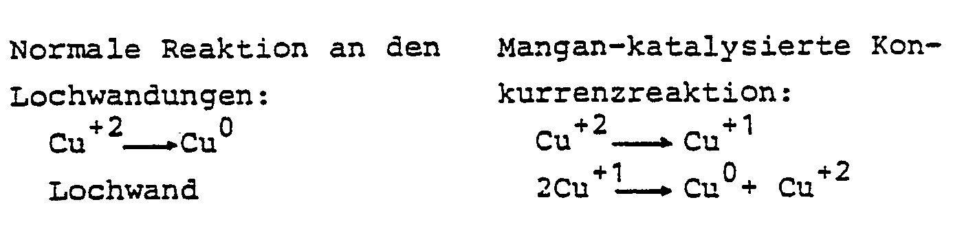
Die Geschwindigkeit dieser Mangan-katalysierten Konkurrenzreaktion steigt mit zunehmender Badaktivität und es ist folglich nicht möglich, die Aktivität des Kupferabscheidungsbades durch Erhöung des Formaldehydgehaltes und des pH zu steigern, um das Auftreten von Löchern in der abgeschiedenen Metallschicht zu vermeiden, da dies in Gegenwart manganhaltiger Rückstände zu einer erhöhten Instabilität der Badlösung führt.The speed of this manganese-catalyzed competition increases with increasing bath activity and it is consequently not possible to increase the activity of the copper deposition bath by increasing the formaldehyde content and the pH in order to avoid the occurrence of holes in the deposited metal layer, since this occurs in the presence of manganese-containing residues leads to increased instability of the bath solution.
Das in Beispiel 1 beschriebene Verfahren wurde wiederholt, wobei jedoch nur eine Lösung zur Lochreinigung eingesetzt wurde, die 60 g/I Kaliumpermanganat und 0,2 g/I eines Fluoroalkylcarboxylats enthielt und in der die Platten 30 Minuten verblieben. Nach der Neutralisation und dem Spülen wurde die eine Platte - im Gegensatz zur anderen - in eine Lösung aus 19 mol/1 NaOH bei 95°C eingebracht. Beide Platten wurden anschließend mit Königswasser zum Entfernen der Manganrückstände behandelt. Die beiden so erhaltenen Lösungen wurden auf ihren Mangangehalt untersucht; die Lösung der Platte, die nicht mit der NaOH-Lösung behandelt worden war, wies 0,10 mg Mangan auf, während die Lösung der Platte, die der Behandlung mit NaOH unterzogen worden war, nur einen Mangangehalt von 0,04 mg aufwies.The procedure described in Example 1 was repeated, but using only a hole cleaning solution which contained 60 g / l of potassium permanganate and 0.2 g / l of a fluoroalkyl carboxylate and in which the plates remained for 30 minutes. After neutralization and rinsing, one plate - unlike the other - was placed in a solution of 19 mol / 1 NaOH at 95 ° C. Both plates were then treated with aqua regia to remove the manganese residues. The two solutions thus obtained were examined for their manganese content; the solution of the plate which had not been treated with the NaOH solution had 0.10 mg of manganese, while the solution of the plate which had been subjected to the treatment with NaOH had only a manganese content of 0.04 mg.
Dieses Beispiel beschreibt die Anwendung des erfindungsgemäßen Verfahrens für die Herstellung von Mehrebenenschaltungen.This example describes the use of the method according to the invention for the production of multilevel circuits.
Ober- und Unterseite der Platte bestanden aus 35 µm starker Kupferfolie. Im Innern der Platte trennten Epoxydglasgewebeschichten von zwischen 100 und 150 µm sechs Ebenen mit Leiterbahnen aus 35 µm dickem Kupfer voneinander.The top and bottom of the plate consisted of 35 µm thick copper foil. Inside the plate, epoxy glass fabric layers of between 100 and 150 µm separated six levels with interconnects made of 35 µm thick copper.
Derartige Schaltungsplatten werden mittels üblicher Laminierungsverfahren hergestellt und weisen durchgehende Bohrungen mit einem Durchmesser von ca. 1 mm auf.Circuit boards of this type are produced by means of customary lamination processes and have continuous bores with a diameter of approximately 1 mm.
Mikroskopische Untersuchungen von Schnitten durch eine Reihe solcher Bohrungen zeigen durch den Bohrvorgang verursachte Harzverschmierungen und -rückstände auf den Lochwandungen einschließlich den durch Kupferschichten gebildeten Bereichen derselben.Microscopic examination of cuts through a series of such bores shows resin smear and residues caused by the drilling process on the hole walls including the areas thereof formed by copper layers.
Zum Entfernen der Harzverschmierungen und -rückstände und zur Metallabscheidung wurden die mit Löchern versehenen Mehrebenen-Schaltungsplatten wie folgt behandelt:
- 1. Die Platten werden für 20 Min. in eine auf 65 °C temperierte Lösung der folgenden Zusammensetzung eingebracht:sowie NaOH in ausreichender Menge, um

den pH auf 12,8 einzustellen. - 2. Eintauchen für 3 Min. in ein Neutralisationsbad, das 20 g/I Natriumbisulfit und eine ausreichende Menge Schwefelsäure zum Einstellen des pH auf 4,5 enthält, bei Raumtemperatur.
- 3. Ein zweiter Neutralisationsschritt wie in 2. für 3 Min.
- 4. Spülen unter fließendem Wasser für 5 Min.
- 5.
Eintauchen für 20 Min. in eine auf 60 °C temperierte Lösung folgender Zusammensetzung :
- 6. Spülen unter fließendem Wasser für 5 Minuten.
- 7. Ausheizen zum Entfernen der Feuchtigkeit in einem Ofen bei 120 °C über einen Zeitraum von 1 Stunde.
- 8. Eintauchen in eine bekannte wässrige Vorbehandlungslösung für 6 Min. bei 60 °C. Diese Lösung enthält eine Mischung von kationischen und anionischen oberflächenaktiven Substanzen und ein Alkanolamin bei einem pH von 2.
- 9. Spülen unter fHeßendem Wasser für 5 Minuten.
- 10. Einbringen in eine milde Kupferätzlösung bei Raumtemperatur für eine Minute ; die Lösung enthält 60 g/I Natriumpersultat und eine ausreichende Menge Schwefelsäure, um den pH auf 2,5 einzustellen.
- 11. Spülen unter fließendem Wasser für 5 Minuten.
- 12. Eintauchen in eine Entoxidierungslösung aus 900 ml/I Wasser und 100 ml/l Schwefelsäure bei Raumtemperatur für 1 Minute.
- 13. Spülen unter fließendem Wasser für 5 Minuten.
- 14. Eintauchen in eine angesäuerte Lösung von Zinnchlorid in einer Kochsalzsole bei Raumtemperatur für 3 Minuten.
- 15. Eintauchen in eine Palladium-Zinn-Chloridlösung bei 45 °C für 10 Minuten. Diese Katalysatorlösung besteht aus 30 ml einer Lösung entsprechend Beispiel 1 von DE-PS 24 34 638 und 970 ml einer 20 %igen Kochsalzlösung.
- 16. Spülen unter fließendem Wasser für 5 Minuten.
- 17. Eintauchen in eine wässrige Fluorborsäurelösung bei Raumtemperatur für 2 Minuten.
- 18. Spülen unter fließendem Wasser für 5 Minuten.
- 19. Eintauchen für 30 Minuten in ein stromlos arbeitendes Verkupferungsbad der folgenden Zusammensetzung :

- 1. The plates are placed in a solution of the following composition, heated to 65 ° C., for 20 minutes: and NaOH in sufficient amount to adjust the pH to 12.8.
- 2. Immerse for 3 minutes in a neutralization bath containing 20 g / l sodium bisulfite and a sufficient amount of sulfuric acid to adjust the pH to 4.5 at room temperature.
- 3. A second neutralization step as in 2. for 3 min.
- 4. Rinse under running water for 5 min.
- 5. Immerse for 20 minutes in a solution of the following composition, heated to 60 ° C:
- 6. Rinse under running water for 5 minutes.
- 7. Bake to remove moisture in an oven at 120 ° C for 1 hour.
- 8. Immerse in a known aqueous pretreatment solution for 6 min. At 60 ° C. This solution contains a mixture of cationic and anionic surface-active substances and an alkanolamine at a pH of 2.
- 9. Rinse under hot water for 5 minutes.
- 10. Put in a mild copper etching solution at room temperature for one minute; the solution contains 60 g / l sodium persate and a sufficient amount of sulfuric acid to adjust the pH to 2.5.
- 11. Rinse under running water for 5 minutes.
- 12. Immerse in a deoxidizing solution of 900 ml / l water and 100 ml / l sulfuric acid at room temperature for 1 minute.
- 13. Rinse under running water for 5 minutes.
- 14. Immerse in an acidified solution of tin chloride in a brine at room temperature for 3 minutes.
- 15. Immerse in a palladium-tin-chloride solution at 45 ° C for 10 minutes. This catalyst solution consists of 30 ml of a solution corresponding to Example 1 of DE-PS 24 34 638 and 970 ml of a 20% saline solution.
- 16. Rinse under running water for 5 minutes.
- 17. Immerse in an aqueous fluoroboric acid solution at room temperature for 2 minutes.
- 18. Rinse under running water for 5 minutes.
- 19. Immerse for 30 minutes in an electroless copper plating bath of the following composition:
Bei den Verfahrensschritten 1, 2, 3, 5, 8, 10, 12, 15, 17 und 19 werden die Platten wie beschrieben, bewegt.In process steps 1, 2, 3, 5, 8, 10, 12, 15, 17 and 19, the plates are moved as described.
Aus dem stromlos arbeitenden Metallabscheidungsbad entsprechend Beispiel 3 wurde auf den Lochwandungen und auf der Kupferoberfläche der Platten eine 2 µm dicke Kupferschicht abgeschieden. Nach dem Spülen und Trocknen wurde die Kupferschicht auf den Lochwandungen nach bekannten Verfahren galvanisch bis zu einer Gesamtschichtdicke von 30 bis 35 µm verstärkt. Die Kupferfolien auf der Ober- und Unterseite der Platten wurden mit einer gebräuchlichen Abdeckmaske versehen und die Leiterzugbahnen durch Ätzen des freiliegenden Kupfers hergestellt.A 2 μm thick copper layer was deposited on the hole walls and on the copper surface of the plates from the electroless metal deposition bath according to Example 3. After rinsing and drying, the copper layer on the hole walls became known Process galvanically reinforced up to a total layer thickness of 30 to 35 µm. The copper foils on the top and bottom of the plates were provided with a customary mask and the conductor tracks were made by etching the exposed copper.
Die so hergestellte Mehrebenen-Schaltungsplatte wies glatte Lochwandungen ohne Epoxydrückstände oder Harzverschmierungen auf dem Kupfer der innen Schaltungsebenen auf ; das abgeschiedene Kupfer bildete eine ununterbrochene, lückenlose Schicht. Die Haftung zwischen stromlos abgeschiedenem Kupfer und Folienkupfer war ausgezeichnet.The multilevel circuit board produced in this way had smooth perforated walls without epoxy residues or resin smearings on the copper of the inner circuit planes; the deposited copper formed an uninterrupted, gapless layer. The adhesion between electrolessly deposited copper and foil copper was excellent.
Dieses Beispiel zeigt die Anwendung des erfindungsgemäßen Verfahrens bei der Herstellung einer Mehrebenen-Schaltungsplatte aus glasfaserverstärktem Polyimid mit Ober- und Unterseiten aus je 35 µm dicker Kupferfolie und sechs inneren Leiterzugebenen aus je 35 µm dickem Kupfer, die durch glasfaserverstärktes Polyimid in einer Schichtdicke von 100 bis 150 wm voneinander getrennt sind. Zwischen den Schichten aus glasfaserverstärktem Polyimid und dem Kupfer befindet sich jeweils eine sehr dünne Schicht aus Akrylharz, die die Haftung zwischen den Polyimid- und den Kupferschichten gewährleistet.This example shows the application of the method according to the invention in the production of a multilevel circuit board made of glass fiber reinforced polyimide with top and bottom sides made of 35 μm thick copper foil and six inner conductor lines each made of 35 μm thick copper, which are coated with glass fiber reinforced polyimide in a layer thickness of 100 to 150 wm are separated. There is a very thin layer of acrylic resin between the layers of glass fiber reinforced polyimide and the copper, which ensures the adhesion between the polyimide and copper layers.
Löcher mit einem Durchmesser von ungefähr 1 mm wurden durch die Mehrebenen-Schaltungsplatte gebohrt. Mikroskopische Untersuchungen der Lochwandungen zeigten Rückstände auf den Kupferschichten, die vermutlich aus dem Akrylharzkleber oder aus diesem und dem Polyimid bestanden. Die Platte wurde, wie in Beispiel 3 beschrieben, gereinigt und mit Metall beschichtet.Holes approximately 1 mm in diameter were drilled through the multilevel circuit board. Microscopic examinations of the hole walls showed residues on the copper layers, which presumably consisted of the acrylic resin adhesive or of this and the polyimide. The plate was cleaned as described in Example 3 and coated with metal.
Die so hergestellte Mehrebenen-Schaltungsplatte hatte glatte Lochwandungen, die frei von Rückständen waren und keinerlei Lücken in der Metallbeschichtung oder unbeschichtete Bereiche aufwiesen. Die Haftung zwischen der abgeschiedenen Kupferschicht und dem Folienkupfer war ausgezeichnet.The multilevel circuit board produced in this way had smooth perforated walls which were free of residues and had no gaps in the metal coating or uncoated areas. The adhesion between the deposited copper layer and the foil copper was excellent.
Dieses Beispiel zeigt, daß bei der Herstellung von Mehrebenen-Schaltungsplatten aus Epoxidglasgewebe als Basismaterial die erfindungsgemäße Behandlung mit Alkali zum Entfernen der manganhaltigen Rückstände von den Lochwandungen erforderlich ist.This example shows that in the production of multilevel circuit boards from epoxy glass fabric as the base material, the treatment according to the invention with alkali is required to remove the manganese-containing residues from the hole walls.
Eine erste Gruppe von Mehrebenen-Schaltungsplatten aus Epoxidglasgewebe mit einer Ober- und Unterseite aus Kupferfolie und zwei inneren Kupferschichten mit durch Ätzen hergestellten Leitermustern wurde, wie in Beispiel 3 beschrieben, gereinigt und mit Kupfer beschichtet. Jede der Kupferschichten hatte eine Stärke von 35 µm und wurde durch 450 µm dicke Schichten aus Epoxidglasgewebe voneinander getrennt. Die Lochwandungen der so behandelten Mehrebenen-Schaltungsplatten wiesen keinerlei Epoxidrückstände oder -verschmierungen oder unbeschichtete Bereiche auf ; die Haftfestigkeit zwischen abgeschiedenem Kupfer und Folienkupfer war ausgezeichnet.A first group of multilevel circuit boards made of epoxy glass fabric with an upper and lower side made of copper foil and two inner copper layers with conductor patterns produced by etching were cleaned as described in Example 3 and coated with copper. Each of the copper layers had a thickness of 35 µm and was separated from one another by 450 µm layers of epoxy glass fabric. The perforated walls of the multilevel circuit boards treated in this way had no epoxy residues or smears or uncoated areas; the adhesive strength between the deposited copper and foil copper was excellent.
Eine zweite Gruppe von Mehrebenen-Schaltungsplatten wie oben beschrieben wurde ebenfalls, wie in Beispiel 3 beschrieben, behandelt, jedoch wurden die Verfahrensschritte 5 und 6 weggelassen. Eine beträchtliche Anzahl der Lochwandungen wies kleine Bereiche auf, die nicht mit Metall beschichtet waren, obgleich keine Epoxidrückstände oder -verschmierungen festgestellt werden konnten und die Haftung zwischen abgeschiedenem und Folienkupfer ausgezeichnet war. Platten mit den festgestellten Fehlern müßten in der gewerblichen Fertigung einem erneuten Kupferabscheidungsvorgang unterzogen werden, um die unbeschichteten Bereiche zu verkupfern.A second group of multilevel circuit boards as described above were also treated as described in Example 3, but steps 5 and 6 were omitted. A considerable number of the hole walls had small areas that were not coated with metal, although no epoxy residues or smears could be found and the adhesion between the deposited and foil copper was excellent. Plates with the defects found would have to be subjected to a new copper deposition process in commercial production in order to copper the uncoated areas.
Dieses Ergebnis bestätigt die Notwendigkeit einer Alkalibehandlung im Rahmen des beschriebenen erfindungsgemäßen Verfahrens.This result confirms the need for an alkali treatment in the process according to the invention described.
Dieses Beispiel beschreibt den Zusatz eines Komplexbildners zur Alkalihydroxid-Lösung.This example describes the addition of a complexing agent to the alkali hydroxide solution.
MultiwireRTM-Platten wurden, wie in Beispiel 1 beschrieben, hergestellt. Die Lochreinigung wurde wie folgt durchgeführt :
- 1. Eintauchen in eine wässrige Lösung von 60 g/I Kaliumpermanganat und 0,2 g/I Fluoroalkylcarboxylat bei einem
pH von 12,5 und 60 °C für 1 Stunde. - 2. Eintauchen in eine Neutralisationslösung, die 30 g/I Zinn (11) chlorid enthält, wie in Beispiel 1 beschrieben, für 3 Minuten.
- 3. Eintauchen in eine Neutralisationslösung, die 3 g/I Zinn(11) chlorid enthält, für 3 Minuten.
- 4. Spülen unter fließendem Wasser für 5 Minuten.
- 5. Eintauchen in eine Lösung der folgenden Zusammensetzung für 30 Minuten bei 45 °C :

- 6. Spülen unter fließendem Wasser für 5 Minuten.
- 7. Einbringen in ein ohne äußere Stromzufuhr arbeitendes Kupferabscheidungsbad folgender Zusammensetzung :

- 1. Immerse in an aqueous solution of 60 g / I potassium permanganate and 0.2 g / I fluoroalkyl carboxylate at a pH of 12.5 and 60 ° C for 1 hour.
- 2. Immerse in a neutralization solution containing 30 g / l of tin (11) chloride as described in Example 1 for 3 minutes.
- 3. Immerse in a neutralization solution containing 3 g / l tin (11) chloride for 3 minutes.
- 4. Rinse under running water for 5 minutes.
- 5. Immerse in a solution of the following composition for 30 minutes at 45 ° C:
- 6. Rinse under running water for 5 minutes.
- 7. Place in a copper plating bath of the following composition, which works without external power supply:
Nach 8 Stunden hatte sich eine einheitliche Kupferschicht von 50 µm Dicke an den Lochwandungen abgeschieden, die fest an den Drahtenden haftete.After 8 hours, a uniform copper layer 50 µm thick had deposited on the hole walls, which adhered firmly to the wire ends.
Dieses Beispiel zeigt die Anwendung des erfindungsgemäßen Verfahrens bei der Herstellung einer Mehrebenen-Schaltungsplatte mit vier Leiterzugebenen.This example shows the application of the method according to the invention in the production of a multilevel circuit board with four conductor levels.
Die Ober- und Unterseite der Platte sowie die zwei inneren Ebenen bestehen aus Kupfer und sind durch Schichten eines Epoxidglasgewebes voneinander getrennt. In die Platte wurden Löcher gebohrt, deren Wandungen Harzverschmierungen aufwiesen. Für die Metallabscheidung wurden folgende Verfahrensschritte durchgeführt :
- 1. Eintauchen in eine Lösung aus 60 g/l KMn04 und einer ausreichenden Menge NaOH, um
den pH auf 12,5 einzustellen, bei 60 °C für eine Stunde. - 2. Eintauchen in eine Neutralisationslösung aus 30 g/I SnCl2. 2H20 und 300 ml/I konz HCI (37 %) bei 20 bis 25 °C.
- 3. Spülen unter fließendem Wasser für 5 Minuten.
- 4. Eintauchen für 20 Minuten in eine 60 °C heiße Lösung, die 150 g/l NaOH enthält.
- 5. Spülen unter fließendem Wasser für 5 Minuten.
- 6. Entoxidieren für 3 Min. in einer Lösung, die 180 g/l H2SO4 enthält.
- 7. Spülen unter fließendem Wasser für 1
Minute bei 20 bis 25 °C. - 8.
Eintauchen für 10 Min. in eine Sensibilisierungslösung aus 1 g/I Palladiumchlorid, 60 g/I Zinn(II) chlorid, und 100 g/I konz. HCI (37 %) (in Form des in DE-AS 14 46 224 beschriebenen Palladiumchlorid-Zinn(II) chlorid-Komplexes). - 9. Spülen in Wasser.
- 10. Einbringen in ein stromlos Kupfer abscheidendes Bad (entsprechend Beispiel 7 US-PS 3 672 986) bei einer Temperatur von 55 °C für einen Zeitraum von 50 Stunden ; es wird eine Kupferschicht von 25 µm abgeschieden.
- 11. Trocknen der Platte an der Luft.
- 1. Immerse in a solution of 60 g / l KMn0 4 and a sufficient amount of NaOH to adjust the pH to 12.5 at 60 ° C for one hour.
- 2. Immerse in a neutralization solution of 30 g / l SnCl 2 . 2H 2 0 and 300 ml / I conc. HCI (37%) at 20 to 25 ° C.
- 3. Rinse under running water for 5 minutes.
- 4. Immerse for 20 minutes in a 60 ° C solution containing 150 g / l NaOH.
- 5. Rinse under running water for 5 minutes.
- 6. Deoxidize for 3 min in a solution containing 180 g / l H 2 SO 4 .
- 7. Rinse under running water for 1 minute at 20 to 25 ° C.
- 8. Immerse for 10 minutes in a sensitizing solution consisting of 1 g / l palladium chloride, 60 g / l tin (II) chloride, and 100 g / l conc. HCl (37%) (in the form of the palladium chloride-tin (II) chloride complex described in DE-AS 14 46 224).
- 9. Rinse in water.
- 10. placing in an electroless copper plating bath (according to Example 7 US Pat. No. 3,672,986) at a temperature of 55 ° C. for a period of 50 hours; a 25 µm copper layer is deposited.
- 11. Air dry the plate.
Die Leiterzugmuster auf den Außenseiten der Platten wurden im herkömmlichen Druck- und Ätzverfahren hergestellt. Die Haftung zwischen dem stromlos an den Lochwandungen abgeschiedenen Kupfer und dem Kupfer der vier Leiterzugebenen war gut und die stromlos abgeschiedene Kupferschicht wies keine Unterbrechungen auf.The conductor pattern on the outside of the plates was produced using conventional printing and etching processes. The adhesion between the copper which was electrolessly deposited on the hole walls and the copper of the four conductors was good and the electrolessly deposited copper layer showed no interruptions.
Selbstverständlich kann die Ober- und Unterseite der Platte statt mit Kupferfolie mit einer Kleberschicht versehen sein, wie in DE-PS 16 65 314 beschrieben, und das Leiterzugmuster nach dem Additiv-Verfahren hergestellt werden. In diesem Fall kann die Platte im Anschluß an den Verfahrensschritt 9 getrocknet und mit einer Resistmaske versehen werden. Es ist dann kein Ätzvorgang erforderlich, um die Leiterzugmuster auf den Außenseiten der Platte herzustellen.Of course, the top and bottom of the plate can be provided with an adhesive layer instead of copper foil, as described in DE-PS 16 65 314, and the conductor pattern can be produced by the additive method. In this case, the plate can be dried after process step 9 and provided with a resist mask. No etching is then required to produce the conductor pattern on the outside of the board.
Nach einem anderen, in DE-PS 16 96 604 beschriebenen Additiv-Verfahren können das Epoxidglasmaterial und die Kleberschicht an den Plattenoberflächen bereits einen Katalysator enthalten, so daß der oben beschriebene Schritt 8 entfällt. Die stromlose Metallabscheidung erfolgt dann direkt im Anschluß an das Aufbringen der Resistmaske.According to another additive method described in DE-PS 16 96 604, the epoxy glass material and the adhesive layer on the plate surfaces can already contain a catalyst, so that step 8 described above is omitted. Electroless metal deposition then takes place immediately after the resist mask has been applied.
Die im Beispiel 7 beschriebenen Verfahrensschritte werden wiederholt, wobei jedoch die Schritte 1 und 4 wie folgt geändert werden :
- - im Schritt 1 : KMnO4 0,5 mol/l
- - im Schritt 4 :
NaOH 20 mol/I
bei Temperaturen von 90 °C und einer
- - in step 1: KMnO 4 0.5 mol / l
- - in step 4:
NaOH 20 mol / I
at temperatures of 90 ° C and a treatment time of 20 minutes.
Die stromlos abgeschiedenen Kupferschichten waren lückenlos und wiesen eine ausgezeichnete Haftung auf dem Kupfer der inneren Schaltungsebenen auf.The electrolessly deposited copper layers were gapless and had excellent adhesion to the copper of the inner circuit levels.
Das im Beispiel 6 beschriebene Verfahren wird wiederholt, wobei jedoch die Schritte 2 und 3 durch die folgenden ersetzt wurden :
- - Spülen in stehendem Wasser für 1 Minute
- - Einbringen in eine Lösung aus 50 g/I Hydroxylamin-
Hydrochlorid und 20 ml/I konz. HCI (37 %).
- - Rinse in standing water for 1 minute
- - Place in a solution of 50 g / I hydroxylamine hydrochloride and 20 ml / I conc. HCI (37%).
Außerdem wurde im Schritt 5 kein Natrium-Kaliumtartrat verwendet.In addition, no sodium potassium tartrate was used in step 5.
Das im Beispiel 7 beschriebene Verfahren wird wiederholt, wobei im Schritt 4 das Natriumhydroxid durch 150 g/I KOH ersetzt wurde.The procedure described in Example 7 is repeated, with step 4 replacing the sodium hydroxide with 150 g / l KOH.
Die hergestellten Metallschichten wiesen die gleiche Güte auf wie die nach dem unveränderten Beispiel 7 hergestellten.The metal layers produced had the same quality as those produced according to the unchanged example 7.
Dieses Beispiel beschreibt die Verwendung einer weiteren Neutralisationslösung bei der Durchführung des im Beispiel 7 beschriebenen Verfahrens, wobei anstelle des Schrittes 2 die folgende Behandlung tritt :
- - Eintauchen für 5 Minuten in eine Lösung mit einem pH von 4,5 aus 30 g/I NaHS03 bei 20 bis 25 °C.
- - Immerse for 5 minutes in a solution with a pH of 4.5 from 30 g / l NaHS0 3 at 20 to 25 ° C.
Es wird wie in Beispiel 7 verfahren bis auf den Schritt 4 : stattdessen wurde die Platte für 20 Min. in eine 60 °C heiße Lösung aus 150 g/I LiOH eingebracht. Die erzielten Ergebnisse entsprachen denjenigen, die bei der Durchführung des unveränderten Beispiels 7 erzielt wurden.The procedure is as in Example 7, except for step 4: instead, the plate was placed in a solution of 150 g / l of LiOH at 60 ° C. for 20 minutes. The results obtained corresponded to those which were achieved when the unchanged example 7 was carried out.
Die im Beispiel 7 beschriebenen Verfahrensschritte wurden wiederholt, wobei jedoch im Schritt 1 die Platte für 1 Stunde in eine 60 °C heiße Lösung aus 60 g/I NaMn04 und einer ausreichenden Menge NaOH, um den pH auf 12,5 einzustellen, getaucht wurde.The process steps described in Example 7 were repeated, but in step 1 the plate was immersed for 1 hour in a 60 ° C. solution of 60 g / l NaMnO 4 and a sufficient amount of NaOH to adjust the pH to 12.5 .
Auch hier wurden Ergebnisse erzielt, die denen bei Durchführung des unveränderten Beispiels 7 entsprachen.Here, too, results were obtained which corresponded to those when the unchanged example 7 was carried out.
Es wurde, wie in Beispiel 6 beschrieben, verfahren, wobei jedoch anstelle des Schrittes 5 die Platte für 40 Min. bei 60 °C in eine 10 %ige Lösung von Tetramethylammoniumhydroxid getaucht wurde.The procedure was as described in Example 6, but, instead of step 5, the plate was immersed in a 10% strength solution of tetramethylammonium hydroxide at 60 ° C. for 40 minutes.
Die Ergebnisse entsprachen denen des unverändert durchgeführten Beispiels 6.The results corresponded to those of Example 6 carried out unchanged.
Das im Beispiel 7 beschriebene Verfahren wurde wiederholt, wobei jedoch anstelle des dort beschriebenen Schrittes 1 wie folgt verfahren wurde :
- - Eintauchen für eine Stunde in eine Lösung von 60 °C, die 60 g/I KMn04, 40 g/l K2C03 und eine ausreichende Menge KOH zum Einstellen des pH auf 12.5 enthielt.
- - Immersion for one hour in a solution of 60 ° C, the 60 g / I KMn0 4 , 40 g / l K 2 C0 3 and a sufficient amount of KOH to adjust the pH to 12.5.
Die Ergebnisse entsprachen denen des unverändert durchgeführten Beispiels 7.The results corresponded to those of Example 7 carried out unchanged.
Claims (11)
Priority Applications (1)
| Application Number | Priority Date | Filing Date | Title |
|---|---|---|---|
| AT83730109T ATE40627T1 (en) | 1982-11-19 | 1983-11-11 | METHOD OF CLEANING HOLES IN PRINTED CIRCUIT BOARDS USING PERMANGANATE AND BASIC SOLUTIONS. |
Applications Claiming Priority (2)
| Application Number | Priority Date | Filing Date | Title |
|---|---|---|---|
| US443160 | 1982-11-19 | ||
| US06/443,160 US4425380A (en) | 1982-11-19 | 1982-11-19 | Hole cleaning process for printed circuit boards using permanganate and caustic treating solutions |
Publications (3)
| Publication Number | Publication Date |
|---|---|
| EP0109920A2 EP0109920A2 (en) | 1984-05-30 |
| EP0109920A3 EP0109920A3 (en) | 1985-09-18 |
| EP0109920B1 true EP0109920B1 (en) | 1989-02-01 |
Family
ID=23759658
Family Applications (1)
| Application Number | Title | Priority Date | Filing Date |
|---|---|---|---|
| EP83730109A Expired EP0109920B1 (en) | 1982-11-19 | 1983-11-11 | Process for cleaning holes in printed circuit boards with permanganate and basic solutions |
Country Status (11)
| Country | Link |
|---|---|
| US (1) | US4425380A (en) |
| EP (1) | EP0109920B1 (en) |
| JP (1) | JPS59104197A (en) |
| AT (1) | ATE40627T1 (en) |
| AU (1) | AU1966883A (en) |
| CH (1) | CH662692A5 (en) |
| DE (2) | DE3379153D1 (en) |
| FR (1) | FR2536623B1 (en) |
| GB (1) | GB2134140B (en) |
| IL (1) | IL70040A (en) |
| ZA (1) | ZA837099B (en) |
Families Citing this family (70)
| Publication number | Priority date | Publication date | Assignee | Title |
|---|---|---|---|---|
| US4597988A (en) * | 1983-06-06 | 1986-07-01 | Macdermid, Incorporated | Process for preparing printed circuit board thru-holes |
| US4756930A (en) * | 1983-06-06 | 1988-07-12 | Macdermid, Incorporated | Process for preparing printed circuit board thru-holes |
| US4515829A (en) * | 1983-10-14 | 1985-05-07 | Shipley Company Inc. | Through-hole plating |
| US4601999A (en) * | 1983-11-09 | 1986-07-22 | William B. Retallick | Metal support for a catalyst |
| US4948630A (en) * | 1984-06-07 | 1990-08-14 | Enthone, Inc. | Three step process for treating plastics with alkaline permanganate solutions |
| US4629636A (en) * | 1984-06-07 | 1986-12-16 | Enthone, Incorporated | Process for treating plastics with alkaline permanganate solutions |
| US4820548A (en) * | 1984-06-07 | 1989-04-11 | Enthone, Incorporated | Three step process for treating plastics with alkaline permanganate solutions |
| US4592852A (en) * | 1984-06-07 | 1986-06-03 | Enthone, Incorporated | Composition and process for treating plastics with alkaline permanganate solutions |
| US4601784A (en) * | 1985-05-31 | 1986-07-22 | Morton Thiokol, Inc. | Sodium permanganate etch baths containing a co-ion for permanganate and their use in desmearing and/or etching printed circuit boards |
| US4601783A (en) * | 1985-05-31 | 1986-07-22 | Morton Thiokol, Inc. | High concentration sodium permanganate etch batch and its use in desmearing and/or etching printed circuit boards |
| JPS62287690A (en) * | 1986-06-06 | 1987-12-14 | 日立エーアイシー株式会社 | Manufacture of printed wiring board |
| GB8613960D0 (en) * | 1986-06-09 | 1986-07-16 | Omi International Gb Ltd | Treating laminates |
| CA1283031C (en) * | 1986-07-01 | 1991-04-16 | Digital Equipment Corporation | On-line filtration of potassium permanganate solutions |
| US4885036A (en) * | 1986-07-01 | 1989-12-05 | Digital Equipment Corporation | On-line filtration of potassium permanganate |
| JPS6338588A (en) * | 1986-08-01 | 1988-02-19 | Seiken Kagaku Kk | Alkaline peeling liquid |
| US4749552A (en) * | 1986-08-06 | 1988-06-07 | Ebara Densan Ltd. | Automatic titration analysis apparatus |
| US4976990A (en) * | 1986-09-30 | 1990-12-11 | Macdermid, Incorporated | Process for metallizing non-conductive substrates |
| DE3638630A1 (en) * | 1986-11-11 | 1988-05-26 | Schering Ag | METHOD FOR REMOVING RESIN POLLUTION IN DRILL HOLES FROM CIRCUIT BOARDS |
| US4940510A (en) * | 1987-06-01 | 1990-07-10 | Digital Equipment Corporation | Method of etching in the presence of positive photoresist |
| US4913931A (en) * | 1987-08-18 | 1990-04-03 | Frederickson Jeffrey W | Method and solution for the prevention of smear in the manufacture of printed circuit boards |
| DE3806884C1 (en) * | 1988-03-03 | 1989-09-21 | Blasberg-Oberflaechentechnik Gmbh, 5650 Solingen, De | Through-plated contact printed circuit and method for fabricating it |
| US5032427A (en) * | 1988-04-25 | 1991-07-16 | Macdermid, Incorporated | Process for preparation printed circuit through-holes for metallization |
| WO1989010431A1 (en) * | 1988-04-25 | 1989-11-02 | Macdermid, Incorporated | Process and composition for preparing printed circuit through-holes for metallization |
| US4873136A (en) * | 1988-06-16 | 1989-10-10 | General Electric Company | Method for preparing polymer surfaces for subsequent plating thereon, and improved metal-plated plastic articles made therefrom |
| US4999251A (en) * | 1989-04-03 | 1991-03-12 | General Electric Company | Method for treating polyetherimide substrates and articles obtained therefrom |
| IT1232863B (en) * | 1989-06-27 | 1992-03-05 | Alfachimici Spa | REDUCED CYCLE PROCEDURE FOR THE MANUFACTURE OF PRINTED CIRCUITS, AND COMPOSITION FOR ITS IMPLEMENTATION |
| US5015339A (en) * | 1990-03-26 | 1991-05-14 | Olin Hunt Sub Iii Corp. | Process for preparing nonconductive substrates |
| US5213840A (en) * | 1990-05-01 | 1993-05-25 | Macdermid, Incorporated | Method for improving adhesion to polymide surfaces |
| US5441770A (en) * | 1990-05-18 | 1995-08-15 | Shipley Company Inc. | Conditioning process for electroless plating of polyetherimides |
| US5143592A (en) * | 1990-06-01 | 1992-09-01 | Olin Corporation | Process for preparing nonconductive substrates |
| US5062930A (en) * | 1990-07-24 | 1991-11-05 | Shipley Company Inc. | Electrolytic permanganate generation |
| US5279771A (en) * | 1990-11-05 | 1994-01-18 | Ekc Technology, Inc. | Stripping compositions comprising hydroxylamine and alkanolamine |
| US6242400B1 (en) | 1990-11-05 | 2001-06-05 | Ekc Technology, Inc. | Method of stripping resists from substrates using hydroxylamine and alkanolamine |
| US6000411A (en) * | 1990-11-05 | 1999-12-14 | Ekc Technology, Inc. | Cleaning compositions for removing etching residue and method of using |
| US5198096A (en) * | 1990-11-28 | 1993-03-30 | General Electric Company | Method of preparing polycarbonate surfaces for subsequent plating thereon and improved metal-plated plastic articles made therefrom |
| US5229169A (en) * | 1992-01-21 | 1993-07-20 | General Electric Company | Adhesion of electroless coatings to resinous articles by treatment with permanganate |
| US5290597A (en) * | 1992-04-27 | 1994-03-01 | General Electric Company | Method of treating halogenated polyimide substrates for increasing adhesion of metal layer thereon |
| US5311660A (en) * | 1993-02-10 | 1994-05-17 | International Business Machines Corporation | Methyl chloroform-free desmear process in additive circuitization |
| US6171468B1 (en) | 1993-05-17 | 2001-01-09 | Electrochemicals Inc. | Direct metallization process |
| US6303181B1 (en) | 1993-05-17 | 2001-10-16 | Electrochemicals Inc. | Direct metallization process employing a cationic conditioner and a binder |
| US6710259B2 (en) * | 1993-05-17 | 2004-03-23 | Electrochemicals, Inc. | Printed wiring boards and methods for making them |
| US5374338A (en) * | 1993-10-27 | 1994-12-20 | International Business Machines Corporation | Selective electroetch of copper and other metals |
| US5567329A (en) * | 1995-01-27 | 1996-10-22 | Martin Marietta Corporation | Method and system for fabricating a multilayer laminate for a printed wiring board, and a printed wiring board formed thereby |
| US5595668A (en) * | 1995-04-05 | 1997-01-21 | Electro-Films Incorporated | Laser slag removal |
| US5998237A (en) * | 1996-09-17 | 1999-12-07 | Enthone-Omi, Inc. | Method for adding layers to a PWB which yields high levels of copper to dielectric adhesion |
| US6141870A (en) | 1997-08-04 | 2000-11-07 | Peter K. Trzyna | Method for making electrical device |
| US5985040A (en) * | 1998-09-21 | 1999-11-16 | Electrochemicals Inc. | Permanganate desmear process for printed wiring boards |
| US6139762A (en) * | 1998-12-11 | 2000-10-31 | Shipley Company, L.L.C. | Methods for manufacture of electronic devices |
| EP1138804A3 (en) * | 2000-03-27 | 2003-06-25 | Infineon Technologies AG | Component with at least two contiguous insulating layers and manufacturing method therefor |
| US6454868B1 (en) | 2000-04-17 | 2002-09-24 | Electrochemicals Inc. | Permanganate desmear process for printed wiring boards |
| US6454954B1 (en) * | 2000-05-22 | 2002-09-24 | Shipley Company, L.L.C. | Desmear etchant and use thereof |
| US20050238812A1 (en) * | 2002-06-04 | 2005-10-27 | Bhangale Sunil M | Method for electroless metalisation of polymer substrate |
| US20050199587A1 (en) * | 2004-03-12 | 2005-09-15 | Jon Bengston | Non-chrome plating on plastic |
| US7364666B2 (en) * | 2004-12-21 | 2008-04-29 | 3M Innovative Properties Company | Flexible circuits and method of making same |
| JP5022576B2 (en) * | 2005-07-08 | 2012-09-12 | 株式会社ジャパンディスプレイイースト | Display panel and display device |
| KR100663266B1 (en) * | 2005-07-11 | 2007-01-02 | 삼성전기주식회사 | Method for producing fine wiring and conductive board |
| JP4452222B2 (en) * | 2005-09-07 | 2010-04-21 | 新光電気工業株式会社 | Multilayer wiring board and manufacturing method thereof |
| KR101277875B1 (en) * | 2006-10-12 | 2013-06-21 | 엘지디스플레이 주식회사 | Liquid Crystal Display Device Responsive to Position of User and Driving Method thereof |
| US7858146B2 (en) * | 2007-06-29 | 2010-12-28 | Rohm And Haas Electronic Materials Llc | Method of electrolessly depositing metal on the walls of through-holes |
| DE102007041991A1 (en) * | 2007-09-05 | 2009-03-12 | Fülling, Rainer, Dr. | Process for the purification of substrates by oxidants and reducing agents and the use of oxidizing agents for the oxidation of extracellular polymeric substances |
| US8247050B2 (en) * | 2009-06-02 | 2012-08-21 | Integran Technologies, Inc. | Metal-coated polymer article of high durability and vacuum and/or pressure integrity |
| US8394507B2 (en) | 2009-06-02 | 2013-03-12 | Integran Technologies, Inc. | Metal-clad polymer article |
| US8741392B2 (en) * | 2009-06-02 | 2014-06-03 | Integran Technologies, Inc. | Anodically assisted chemical etching of conductive polymers and polymer composites |
| US8906515B2 (en) * | 2009-06-02 | 2014-12-09 | Integran Technologies, Inc. | Metal-clad polymer article |
| US9004240B2 (en) | 2013-02-27 | 2015-04-14 | Integran Technologies Inc. | Friction liner |
| JP6350064B2 (en) * | 2013-10-09 | 2018-07-04 | 日立化成株式会社 | Manufacturing method of multilayer wiring board |
| US10381322B1 (en) | 2018-04-23 | 2019-08-13 | Sandisk Technologies Llc | Three-dimensional memory device containing self-aligned interlocking bonded structure and method of making the same |
| US10879260B2 (en) | 2019-02-28 | 2020-12-29 | Sandisk Technologies Llc | Bonded assembly of a support die and plural memory dies containing laterally shifted vertical interconnections and methods for making the same |
| CN112087872B (en) * | 2020-09-30 | 2021-10-12 | 生益电子股份有限公司 | Glue removing process for mixed-compression PCB |
| CN116744562A (en) * | 2023-07-20 | 2023-09-12 | 清远市富盈电子有限公司 | Processing method of high-frequency high-speed PCB and PCB manufactured by processing method |
Citations (1)
| Publication number | Priority date | Publication date | Assignee | Title |
|---|---|---|---|---|
| US4042729A (en) * | 1972-12-13 | 1977-08-16 | Kollmorgen Technologies Corporation | Process for the activation of resinous bodies for adherent metallization |
Family Cites Families (16)
| Publication number | Priority date | Publication date | Assignee | Title |
|---|---|---|---|---|
| CA812207A (en) | 1969-05-06 | Hooker Chemical Corporation | Method of treating metal surfaces | |
| US3141797A (en) | 1961-09-07 | 1964-07-21 | Lubrizol Corp | Phosphating process |
| US3276106A (en) | 1963-07-01 | 1966-10-04 | North American Aviation Inc | Preparation of multilayer boards for electrical connections between layers |
| US3276927A (en) | 1963-07-01 | 1966-10-04 | North American Aviation Inc | Smoothing of mechanically drilled holes |
| US3425947A (en) | 1966-05-02 | 1969-02-04 | Hooker Chemical Corp | Method of treating metal surfaces |
| US3515649A (en) | 1967-05-02 | 1970-06-02 | Ivan C Hepfer | Pre-plating conditioning process |
| US3647699A (en) | 1967-12-22 | 1972-03-07 | Gen Motors Corp | Surface conditioner composition for abs resin |
| US3652417A (en) | 1968-03-01 | 1972-03-28 | Carus Corp | Stabilization of alkali metal permanganate in alkaline solution |
| US3652351A (en) | 1970-05-13 | 1972-03-28 | Carus Corp | Processes for etching synthetic polymer resins with alkaline alkali metal manganate solutions |
| US3689303A (en) | 1970-12-21 | 1972-09-05 | Crown City Plating Co | Process for electroless plating of abs resins |
| DE2239908C3 (en) * | 1972-08-14 | 1979-12-13 | Aeg Isolier- Und Kunststoff Gmbh, 3500 Kassel | Base material for the production of printed circuits |
| US3962496A (en) | 1974-11-07 | 1976-06-08 | Photocircuits Division Of Kollmorgen | Composition and method for neutralizing and sensitizing resinous surfaces and improved sensitized resinous surfaces for adherent metallization |
| US4054693A (en) | 1974-11-07 | 1977-10-18 | Kollmorgen Technologies Corporation | Processes for the preparation of resinous bodies for adherent metallization comprising treatment with manganate/permanganate composition |
| DK154600C (en) * | 1974-11-07 | 1989-04-17 | Kollmorgen Tech Corp | PROCEDURE FOR TREATMENT OF CIRCUIT PLATE PLATE ON FORM DUST BASE. |
| DK485275A (en) * | 1974-11-07 | 1976-05-08 | Kollmorgen Corp | PROCEDURE AND MIXTURE FOR THE PREPARATION OF ITEMS WITH A SOLID ADHESIVE METAL LAYER ON RESINFUL SURFACES |
| JPS5388164A (en) * | 1977-01-12 | 1978-08-03 | Matsushita Electric Ind Co Ltd | Method of producing printed circuit board |
-
1982
- 1982-11-19 US US06/443,160 patent/US4425380A/en not_active Expired - Lifetime
-
1983
- 1983-09-14 JP JP58170562A patent/JPS59104197A/en active Granted
- 1983-09-23 ZA ZA837099A patent/ZA837099B/en unknown
- 1983-09-28 AU AU19668/83A patent/AU1966883A/en not_active Abandoned
- 1983-10-24 IL IL70040A patent/IL70040A/en unknown
- 1983-11-01 GB GB08329133A patent/GB2134140B/en not_active Expired
- 1983-11-11 EP EP83730109A patent/EP0109920B1/en not_active Expired
- 1983-11-11 DE DE8383730109T patent/DE3379153D1/en not_active Expired
- 1983-11-11 DE DE3341431A patent/DE3341431C3/en not_active Expired - Lifetime
- 1983-11-11 AT AT83730109T patent/ATE40627T1/en not_active IP Right Cessation
- 1983-11-17 CH CH6221/83A patent/CH662692A5/en not_active IP Right Cessation
- 1983-11-17 FR FR8318290A patent/FR2536623B1/en not_active Expired
Patent Citations (1)
| Publication number | Priority date | Publication date | Assignee | Title |
|---|---|---|---|---|
| US4042729A (en) * | 1972-12-13 | 1977-08-16 | Kollmorgen Technologies Corporation | Process for the activation of resinous bodies for adherent metallization |
Also Published As
| Publication number | Publication date |
|---|---|
| GB2134140A (en) | 1984-08-08 |
| DE3379153D1 (en) | 1989-03-09 |
| EP0109920A2 (en) | 1984-05-30 |
| JPS6366079B2 (en) | 1988-12-19 |
| ZA837099B (en) | 1984-11-28 |
| CH662692A5 (en) | 1987-10-15 |
| FR2536623B1 (en) | 1987-03-20 |
| JPS59104197A (en) | 1984-06-15 |
| IL70040A (en) | 1988-08-31 |
| AU1966883A (en) | 1984-05-24 |
| DE3341431C3 (en) | 1995-06-01 |
| ATE40627T1 (en) | 1989-02-15 |
| DE3341431A1 (en) | 1984-05-24 |
| EP0109920A3 (en) | 1985-09-18 |
| DE3341431C2 (en) | 1989-10-05 |
| GB8329133D0 (en) | 1983-12-07 |
| IL70040A0 (en) | 1984-01-31 |
| FR2536623A1 (en) | 1984-05-25 |
| GB2134140B (en) | 1986-11-26 |
| US4425380A (en) | 1984-01-10 |
Similar Documents
| Publication | Publication Date | Title |
|---|---|---|
| EP0109920B1 (en) | Process for cleaning holes in printed circuit boards with permanganate and basic solutions | |
| DE2238002C3 (en) | Process for the additive production of patterns consisting of metal deposits | |
| DE3045281C2 (en) | SOLUTION AND METHOD FOR ELECTROCHEMICAL METALLIZATION OF DIELECTRICS | |
| DE4447897B4 (en) | Process for the production of printed circuit boards | |
| DE3002166C2 (en) | ||
| EP0227857B1 (en) | Process for making printed circuits | |
| DE10136078B4 (en) | Aqueous solution for continuous microetching of copper or copper alloy | |
| DE2623716C3 (en) | Process for the pretreatment of polysulf on substrates before electroless plating with a metal | |
| CH631587A5 (en) | METHOD FOR PRODUCING ELECTRIC CIRCUIT BOARDS AND BASE MATERIAL FOR IMPLEMENTING THE METHOD. | |
| DE2457829A1 (en) | METHODS AND SOLUTIONS FOR ELECTRIC METAL APPLICATION | |
| DE3110415C2 (en) | Process for the manufacture of printed circuit boards | |
| DE3047287C2 (en) | Process for the manufacture of a printed circuit | |
| DE2847070A1 (en) | METHOD OF TREATMENT OF A SUBSTRATE PROVIDED WITH ADDITIVE-PLATED PRINTED CONDUCTOR | |
| DE2550598C3 (en) | Process for pretreating printed circuit boards | |
| CH629853A5 (en) | METALIZING METHOD FOR ELECTRICITY. | |
| DE69730288T2 (en) | Device for the production of printed circuit boards with galvanized resistors | |
| DE2831126C2 (en) | Process for the pretreatment of an epoxy resin substrate for electroless copper plating | |
| EP0324189A2 (en) | Process for making electrical-circuit boards | |
| EP0417750B1 (en) | Process for direct metallization of circuit boards | |
| DE3121015A1 (en) | Method of activating pickled surfaces and solution for carrying out said method | |
| DE3006117C2 (en) | Process for the production of printed circuit boards with at least two conductor additions | |
| DE1665314B1 (en) | BASIC MATERIAL FOR THE PRODUCTION OF PRINTED CIRCUITS | |
| DE3931003A1 (en) | Direct metallisation of circuits boards | |
| DE3048665C2 (en) | ||
| CH657491A5 (en) | METHOD FOR PRODUCING PRINTED CIRCUITS. |
Legal Events
| Date | Code | Title | Description |
|---|---|---|---|
| PUAI | Public reference made under article 153(3) epc to a published international application that has entered the european phase |
Free format text: ORIGINAL CODE: 0009012 |
|
| AK | Designated contracting states |
Designated state(s): AT DE IT NL SE |
|
| 17P | Request for examination filed |
Effective date: 19841114 |
|
| PUAL | Search report despatched |
Free format text: ORIGINAL CODE: 0009013 |
|
| AK | Designated contracting states |
Designated state(s): AT DE IT NL SE |
|
| 17Q | First examination report despatched |
Effective date: 19870810 |
|
| GRAA | (expected) grant |
Free format text: ORIGINAL CODE: 0009210 |
|
| RAP1 | Party data changed (applicant data changed or rights of an application transferred) |
Owner name: KOLLMORGEN CORPORATION |
|
| ITF | It: translation for a ep patent filed |
Owner name: DE DOMINICIS & MAYER S.R.L. |
|
| AK | Designated contracting states |
Kind code of ref document: B1 Designated state(s): AT DE IT NL SE |
|
| REF | Corresponds to: |
Ref document number: 40627 Country of ref document: AT Date of ref document: 19890215 Kind code of ref document: T |
|
| REF | Corresponds to: |
Ref document number: 3379153 Country of ref document: DE Date of ref document: 19890309 |
|
| PLBE | No opposition filed within time limit |
Free format text: ORIGINAL CODE: 0009261 |
|
| STAA | Information on the status of an ep patent application or granted ep patent |
Free format text: STATUS: NO OPPOSITION FILED WITHIN TIME LIMIT |
|
| 26N | No opposition filed | ||
| ITTA | It: last paid annual fee | ||
| NLS | Nl: assignments of ep-patents |
Owner name: AMP-AKZO CORPORATION TE NEWARK, DELAWARE, VER. ST. |
|
| PGFP | Annual fee paid to national office [announced via postgrant information from national office to epo] |
Ref country code: AT Payment date: 19921028 Year of fee payment: 10 |
|
| PGFP | Annual fee paid to national office [announced via postgrant information from national office to epo] |
Ref country code: DE Payment date: 19930128 Year of fee payment: 10 |
|
| PG25 | Lapsed in a contracting state [announced via postgrant information from national office to epo] |
Ref country code: AT Effective date: 19931111 |
|
| PG25 | Lapsed in a contracting state [announced via postgrant information from national office to epo] |
Ref country code: DE Effective date: 19940802 |
|
| EAL | Se: european patent in force in sweden |
Ref document number: 83730109.2 |
|
| PGFP | Annual fee paid to national office [announced via postgrant information from national office to epo] |
Ref country code: NL Payment date: 19980914 Year of fee payment: 16 |
|
| PGFP | Annual fee paid to national office [announced via postgrant information from national office to epo] |
Ref country code: SE Payment date: 19981105 Year of fee payment: 16 |
|
| PG25 | Lapsed in a contracting state [announced via postgrant information from national office to epo] |
Ref country code: SE Free format text: LAPSE BECAUSE OF NON-PAYMENT OF DUE FEES Effective date: 19991112 |
|
| PG25 | Lapsed in a contracting state [announced via postgrant information from national office to epo] |
Ref country code: NL Free format text: LAPSE BECAUSE OF NON-PAYMENT OF DUE FEES Effective date: 20000601 |
|
| EUG | Se: european patent has lapsed |
Ref document number: 83730109.2 |
|
| NLV4 | Nl: lapsed or anulled due to non-payment of the annual fee |
Effective date: 20000601 |