EP0109478A1 - Device for controlling vehicle speed - Google Patents
Device for controlling vehicle speed Download PDFInfo
- Publication number
- EP0109478A1 EP0109478A1 EP83104892A EP83104892A EP0109478A1 EP 0109478 A1 EP0109478 A1 EP 0109478A1 EP 83104892 A EP83104892 A EP 83104892A EP 83104892 A EP83104892 A EP 83104892A EP 0109478 A1 EP0109478 A1 EP 0109478A1
- Authority
- EP
- European Patent Office
- Prior art keywords
- actuator
- input
- signal
- alarm
- comparator
- Prior art date
- Legal status (The legal status is an assumption and is not a legal conclusion. Google has not performed a legal analysis and makes no representation as to the accuracy of the status listed.)
- Granted
Links
- 239000000203 mixture Substances 0.000 claims abstract description 4
- 230000002950 deficient Effects 0.000 description 4
- 238000010586 diagram Methods 0.000 description 4
- 230000007257 malfunction Effects 0.000 description 2
- 238000011144 upstream manufacturing Methods 0.000 description 2
- 230000007423 decrease Effects 0.000 description 1
- 230000007547 defect Effects 0.000 description 1
- 238000006073 displacement reaction Methods 0.000 description 1
- 238000000034 method Methods 0.000 description 1
- 238000012544 monitoring process Methods 0.000 description 1
Images
Classifications
-
- B—PERFORMING OPERATIONS; TRANSPORTING
- B60—VEHICLES IN GENERAL
- B60K—ARRANGEMENT OR MOUNTING OF PROPULSION UNITS OR OF TRANSMISSIONS IN VEHICLES; ARRANGEMENT OR MOUNTING OF PLURAL DIVERSE PRIME-MOVERS IN VEHICLES; AUXILIARY DRIVES FOR VEHICLES; INSTRUMENTATION OR DASHBOARDS FOR VEHICLES; ARRANGEMENTS IN CONNECTION WITH COOLING, AIR INTAKE, GAS EXHAUST OR FUEL SUPPLY OF PROPULSION UNITS IN VEHICLES
- B60K31/00—Vehicle fittings, acting on a single sub-unit only, for automatically controlling vehicle speed, i.e. preventing speed from exceeding an arbitrarily established velocity or maintaining speed at a particular velocity, as selected by the vehicle operator
- B60K31/02—Vehicle fittings, acting on a single sub-unit only, for automatically controlling vehicle speed, i.e. preventing speed from exceeding an arbitrarily established velocity or maintaining speed at a particular velocity, as selected by the vehicle operator including electrically actuated servomechanism including an electric control system or a servomechanism in which the vehicle velocity affecting element is actuated electrically
- B60K31/04—Vehicle fittings, acting on a single sub-unit only, for automatically controlling vehicle speed, i.e. preventing speed from exceeding an arbitrarily established velocity or maintaining speed at a particular velocity, as selected by the vehicle operator including electrically actuated servomechanism including an electric control system or a servomechanism in which the vehicle velocity affecting element is actuated electrically and means for comparing one electrical quantity, e.g. voltage, pulse, waveform, flux, or the like, with another quantity of a like kind, which comparison means is involved in the development of an electrical signal which is fed into the controlling means
- B60K31/042—Vehicle fittings, acting on a single sub-unit only, for automatically controlling vehicle speed, i.e. preventing speed from exceeding an arbitrarily established velocity or maintaining speed at a particular velocity, as selected by the vehicle operator including electrically actuated servomechanism including an electric control system or a servomechanism in which the vehicle velocity affecting element is actuated electrically and means for comparing one electrical quantity, e.g. voltage, pulse, waveform, flux, or the like, with another quantity of a like kind, which comparison means is involved in the development of an electrical signal which is fed into the controlling means where at least one electrical quantity is set by the vehicle operator
- B60K31/045—Vehicle fittings, acting on a single sub-unit only, for automatically controlling vehicle speed, i.e. preventing speed from exceeding an arbitrarily established velocity or maintaining speed at a particular velocity, as selected by the vehicle operator including electrically actuated servomechanism including an electric control system or a servomechanism in which the vehicle velocity affecting element is actuated electrically and means for comparing one electrical quantity, e.g. voltage, pulse, waveform, flux, or the like, with another quantity of a like kind, which comparison means is involved in the development of an electrical signal which is fed into the controlling means where at least one electrical quantity is set by the vehicle operator in a memory, e.g. a capacitor
- B60K31/047—Vehicle fittings, acting on a single sub-unit only, for automatically controlling vehicle speed, i.e. preventing speed from exceeding an arbitrarily established velocity or maintaining speed at a particular velocity, as selected by the vehicle operator including electrically actuated servomechanism including an electric control system or a servomechanism in which the vehicle velocity affecting element is actuated electrically and means for comparing one electrical quantity, e.g. voltage, pulse, waveform, flux, or the like, with another quantity of a like kind, which comparison means is involved in the development of an electrical signal which is fed into the controlling means where at least one electrical quantity is set by the vehicle operator in a memory, e.g. a capacitor the memory being digital
-
- B—PERFORMING OPERATIONS; TRANSPORTING
- B60—VEHICLES IN GENERAL
- B60W—CONJOINT CONTROL OF VEHICLE SUB-UNITS OF DIFFERENT TYPE OR DIFFERENT FUNCTION; CONTROL SYSTEMS SPECIALLY ADAPTED FOR HYBRID VEHICLES; ROAD VEHICLE DRIVE CONTROL SYSTEMS FOR PURPOSES NOT RELATED TO THE CONTROL OF A PARTICULAR SUB-UNIT
- B60W30/00—Purposes of road vehicle drive control systems not related to the control of a particular sub-unit, e.g. of systems using conjoint control of vehicle sub-units
- B60W30/18—Propelling the vehicle
- B60W30/18009—Propelling the vehicle related to particular drive situations
- B60W30/18027—Drive off, accelerating from standstill
-
- B—PERFORMING OPERATIONS; TRANSPORTING
- B60—VEHICLES IN GENERAL
- B60W—CONJOINT CONTROL OF VEHICLE SUB-UNITS OF DIFFERENT TYPE OR DIFFERENT FUNCTION; CONTROL SYSTEMS SPECIALLY ADAPTED FOR HYBRID VEHICLES; ROAD VEHICLE DRIVE CONTROL SYSTEMS FOR PURPOSES NOT RELATED TO THE CONTROL OF A PARTICULAR SUB-UNIT
- B60W50/00—Details of control systems for road vehicle drive control not related to the control of a particular sub-unit, e.g. process diagnostic or vehicle driver interfaces
- B60W2050/0001—Details of the control system
- B60W2050/0019—Control system elements or transfer functions
- B60W2050/0028—Mathematical models, e.g. for simulation
- B60W2050/0031—Mathematical model of the vehicle
-
- B—PERFORMING OPERATIONS; TRANSPORTING
- B60—VEHICLES IN GENERAL
- B60W—CONJOINT CONTROL OF VEHICLE SUB-UNITS OF DIFFERENT TYPE OR DIFFERENT FUNCTION; CONTROL SYSTEMS SPECIALLY ADAPTED FOR HYBRID VEHICLES; ROAD VEHICLE DRIVE CONTROL SYSTEMS FOR PURPOSES NOT RELATED TO THE CONTROL OF A PARTICULAR SUB-UNIT
- B60W2530/00—Input parameters relating to vehicle conditions or values, not covered by groups B60W2510/00 or B60W2520/00
- B60W2530/16—Driving resistance
-
- B—PERFORMING OPERATIONS; TRANSPORTING
- B60—VEHICLES IN GENERAL
- B60W—CONJOINT CONTROL OF VEHICLE SUB-UNITS OF DIFFERENT TYPE OR DIFFERENT FUNCTION; CONTROL SYSTEMS SPECIALLY ADAPTED FOR HYBRID VEHICLES; ROAD VEHICLE DRIVE CONTROL SYSTEMS FOR PURPOSES NOT RELATED TO THE CONTROL OF A PARTICULAR SUB-UNIT
- B60W2720/00—Output or target parameters relating to overall vehicle dynamics
- B60W2720/10—Longitudinal speed
- B60W2720/106—Longitudinal acceleration
Definitions
- the invention relates to a device for controlling the driving speed of a motor vehicle with a setpoint generator adjustable by an accelerator pedal, the output signal of which can be applied to an actuator of an element influencing the fuel-air mixture, with an actuator generator that generates a signal corresponding to the position of the actuator, and with an alarm circuit via which an alarm signal can be fed to an alarm device if the actuator is in a gas position when the setpoint transmitter is not actuated.
- a pedal contact that can be actuated by the accelerator pedal and an actuator contact that can be actuated by the actuator are connected in parallel in the alarm circuit.
- the pedal contact is open in the idle position of the accelerator pedal and the actuator contact is closed in the idle position of the actuator. Since the switching point of the Pe dalkontact with a lower deflection of the accelerator pedal from the idle position than the switching point of the actuator contact with corresponding deflection of the actuator from the idle position, current flow through the alarm circuit is always possible with an intact control device, which means that no alarm signal is given. However, if the actuator is not in its idle position even though the accelerator pedal is not actuated, the pedal contact and the actuator contact are open and the current flow in the alarm circuit is thus interrupted. This means that an alarm signal is supplied to the alarm device.
- a first branch of the alarm circuit emits an alarm signal at its output when the setpoint generator generates an idle signal when the accelerator pedal is actuated
- a second branch of the alarm circuit emits an alarm signal at its output when the actuator is actuated Actuator generates an idle signal.
- the alarm signal of the first branch before the alarm signal of the second branch of the alarm circuit can be issued.
- the first branch of the alarm circuit can have a comparator, at whose first input there is a constant electrical signal which corresponds to a specific deflection position of the setpoint generator from the idle position, and at whose second input there is an electrical signal corresponding to the respective position of the setpoint generator, the output the comparator is fed to a first input of an AND gate, at the second input of which a signal can be applied when the accelerator pedal is deflected from the idle position, and according to which the second branch of the alarm circuit has a second comparator, at the first input of which there is a constant electrical signal which corresponds to a specific deflection position of the actuator from the idle position and an electrical signal corresponding to the respective position of the actuator is present at its second input, the output of the second comparator being fed to a first input of a second AND element conducts, at whose second input a signal can be applied when the actuator is deflected from the idle position and that both the output of the first and of the second AND element is connected to the alarm device.
- the second comparator works in the same way in that the first input of the second comparator is the positive input and a signal which decreases in size is present when the actuator is displaced from its idle position when the actuator is displaced from its idle position.
- the input signals of the comparators are generated with simple means if the first input of the first and / or second comparator is connected to a voltage divider and if the second input of the first and / or second comparator is connected to a potentiometer forming the setpoint generator or the actuator transmitter .
- the function of the accelerator pedal is preferably monitored by arranging the second input of the first AND gate with a pedal contact which can be actuated by the accelerator pedal in the idle position of the accelerator pedal and which is closed when the accelerator pedal is actuated, while in the same way monitoring the function of the actuator takes place that the second input of the second AND element is arranged an actuator contact which can be actuated by the actuator in the idle position of the actuator and which is actuated when the actuator is actuated gate is open and when the first input of the AND gate is inverted.
- the input of the AND gate coming from the comparator receives a positive signal until the size of the setpoint signal reaches the constant signal size at the positive comparator input Has. During this time there is still no positive signal due to the open pedal contact at the second input of the AND gate. However, the comparator's positive signal is deleted. Only when the accelerator pedal is deflected further does the pedal switch close and the second input of the AND gate receives a positive signal. However, since there is no longer a positive signal at the first input, the AND gate cannot give an alarm signal to the alarm device.
- the second comparator works according to the same principle, in which the switching point is greater deflection of the actuator than the switching point of the actuator contact. This means that the comparator feeds a positive signal to the second AND gate until the size of the actuator signal reaches the size of the constant signal at the positive input of the comparator. So stale the comparator reverses and feeds a negative signal to the AND gate. Since this signal is inverted at the AND gate, the previously negative signal changes to a positive signal. With further adjustment of the actuator, the previously closed actuator contact opens and the second input of the AND element receives a negative signal instead of a positive one. In the event of a defect in the actuator or the actuator contact, the same signals are present at the inputs of the AND element, so that the latter emits an alarm signal.
- the switching point of the actuator contact is greater deflection of the actuator than the switching point of the pedal contact with a corresponding deflection of the accelerator pedal.
- the alarm device can be a lamp.
- the alarm device can be preceded by a timing element, which is preferably an RC element.
- a permanent and not only brief exposure to the alarm device is achieved if the alarm device has a memory element, e.g. a flip-flop is connected upstream.
- a memory element e.g. a flip-flop is connected upstream.
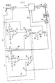
- the device shown in FIG. 1 has a setpoint generator 2 which is adjustable by a gas pedal 1 and is designed as a potentiometer. Its output signal is fed to an electrical controller 3, which controls an actuator drive 4 via an amplifier 9.
- An actuator 5 formed by a throttle valve for influencing the fuel-air mixture and an actuator transmitter 29 formed by a potentiometer can be adjusted.
- the faultless function of the device for controlling the driving speed can be monitored by an alarm circuit consisting of a first branch 6 and a second branch 7, of which an alarm device formed by a lamp 8 can be controlled.
- the first branch 6 of the alarm circuit has a comparator 10, to the first positive input 11 of which a voltage divider 12 is connected.
- This voltage divider 12 applies a constant electrical signal to the input 11, which corresponds to a specific deflection position of the setpoint generator 2 from the idle position of, for example, 8 c .
- the negative second input 13 of the comparator 10 is acted upon by the output signal of the setpoint generator 2, u.z. such that the size of the signal increases with increasing deflection of the setpoint generator 2. If this signal reaches the size of the constant signal present at the input 11, the comparator 10, which had previously emitted a positive signal, now outputs a negative output signal to a first input 15 of an AND gate 14.
- a pedal contact 18 is arranged in the control line 17 of the second input 16 of the AND gate 14, which can be actuated by the accelerator pedal 1 and is open in the idle position of the accelerator pedal with a somewhat greater deflection of approximately 10 ° of the accelerator pedal 1 from the idle position than that by the voltage divider 12 fixed deflection position is closed.
- the second branch 7 of the alarm circuit has a comparator 20, to the first positive input 21 of which a voltage divider 22 is connected.
- the voltage divider applies a constant electrical signal to this input 21, which corresponds to a specific deflection position of approximately 14 ° of the actuator 29 from the idle position.
- the negative second input 23 of the comparator 20 is acted upon by the output signal of the actuator 29, in such a way that the size of the signal increases with increasing displacement of the actuator 29. If this signal reaches the size of the constant signal present at the input 21, the comparator 20, which until then has given a positive signal, now outputs a negative output signal from a first input 25 of an AND gate 24. Since this first input 25 is inverted, the signal which is detected by the AND gate 24 and which is output negatively by the comparator is positive.
- an actuator contact 28 is arranged, which can be actuated by the actuator 5 and closed in the idle position of the actuator with a somewhat smaller deflection of about 12 ° of the actuator 5 from the idle position than that by the voltage divider 22 fixed deflection position is open.
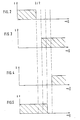
- FIG. 4 shows the signal detected by the AND gate 24 at the inverted input 25 and in FIG. 5 the signal detected at the input 26. From this it can be seen that if the second branch 7 is intact, no alarm signal can be emitted at the output of the AND gate 24.
- the AND element 24 detects two identical signals and thus emits an output signal. Here, too, a false alarm signal is suppressed when switching over by the RC element 19.
- FIGS. 2-5 it can also be seen that the switching point of the actuator contact 28 is greater deflection of the actuator 5 than the switching point of the pedal contact 18 with a corresponding deflection of the accelerator pedal 1. In this way, the two branches 6 and 7 are mutually influenced avoided.
- a storage element 30 configured as a flip-flop upstream of the lamp 8 ensures that the supply line an alarm signal that permanently controls the lamp 8 and thus not only causes it to light up briefly.
- a generated alarm signal is also fed via a line 31 to the controller 3, which is controlled by this alarm signal in such a way that it controls the actuator 4 primarily in a load-reducing manner. A full throttle position of the actuator 5 is thus prevented, but driving at low speed to reach a workshop is made possible.
Landscapes
- Engineering & Computer Science (AREA)
- Transportation (AREA)
- Mechanical Engineering (AREA)
- Chemical & Material Sciences (AREA)
- Combustion & Propulsion (AREA)
- Automation & Control Theory (AREA)
- Auxiliary Drives, Propulsion Controls, And Safety Devices (AREA)
- Control Of Throttle Valves Provided In The Intake System Or In The Exhaust System (AREA)
- Electrical Control Of Air Or Fuel Supplied To Internal-Combustion Engine (AREA)
- Emergency Alarm Devices (AREA)
Abstract
Die Erfindung betrifft eine Einrichtung zum Steuern der Fahrgeschwindigkeit eines Kraftfahrzeuges mit einem von einem Gaspedal 1 verstellbaren Sollwertgeber 2, von dessen Ausgangssignal ein Stellglied 5 eines das Kraftstoff-Luft-Gemisch beeinflussenden Elements beaufschlagbar ist. Sie weist einen ein Signal entsprechend der Stellung des Stellgliedes erzeugenden Stellgliedgeber 29 sowie eine Alarmschaltung 6, 7 auf, über die einer Alarmeinrichtung ein Alarmsignal zuleitbar ist, wenn bei nicht betätigtem Sollwertgeber 2 sich das Stellglied 5 in einer Gasstellung befindet. Die Alarmschaltung 6, 7 ist so ausgebildet, daß auch ein Fehler in der Alarmschaltung 6, 7 anzeigbar ist.The invention relates to a device for controlling the driving speed of a motor vehicle with a setpoint generator 2 that can be adjusted by an accelerator pedal 1, the output signal of which can be applied to an actuator 5 of an element influencing the fuel-air mixture. It has an actuator transmitter 29 which generates a signal corresponding to the position of the actuator and an alarm circuit 6, 7 via which an alarm signal can be fed to an alarm device when the actuator 5 is in a gas position when the setpoint transmitter 2 is not actuated. The alarm circuit 6, 7 is designed such that an error in the alarm circuit 6, 7 can also be indicated.
Description
Die Erfindung bezieht sich auf eine Einrichtung zum Steuern der Fahrgeschwindigkeit eines Kraftfahrzeuges mit einem von einem Gaspedal verstellbaren Sollwertgeber, von dessen Ausgangssignal ein Stellglied eines das Kraftstoff-LuftGemisch beeinflussenden Elements beaufschlagbar ist, mit einem ein Signal entsprechend der Stellung des Stellgliedes erzeugenden Stellgliedgeber, sowie mit einer Alarmschaltung, über die einerßlarmeinrichtung ein Alarmsignal zuleitbar ist, wenn bei nicht betätigtem Sollwertgeber sich das Stellglied in einer Gasstellung befindet.The invention relates to a device for controlling the driving speed of a motor vehicle with a setpoint generator adjustable by an accelerator pedal, the output signal of which can be applied to an actuator of an element influencing the fuel-air mixture, with an actuator generator that generates a signal corresponding to the position of the actuator, and with an alarm circuit via which an alarm signal can be fed to an alarm device if the actuator is in a gas position when the setpoint transmitter is not actuated.
Bei einer derartigen bekannten Einrichtung sind in der Alarmschaltung ein vom Gaspedal betätigbarer Pedalkontakt und ein vom Stellglied betätigbarer Stellgliedkontakt parallel zueinander geschaltet. Dabei ist der Pedalkontakt in der Leerlauf Stellung des Gaspedals geöffnet und der Stellgliedkontakt in der Leerlaufstellung des Stellglieds geschlossen. Da der Schaltpunkt des Pedalkontakts bei einer niedrigeren Auslenkung des Gaspedals aus der Leerlaufposition liegt als der Schaltpunkt des Stellgliedkontakts bei entsprechender Auslenkung des Stellglieds aus der Leerlaufposition , ist bei intakter Steuereinrichtung immer ein Stromfluß durch die Alarmschaltung möglich, was bedeutet, daß kein Alarmsignal abgegeben wird. Befindet sich aber das Stellglied nicht in seiner Leerlaufposition, obwohl das Gaspedal nicht betätigt ist, so sind Pedalkontakt und Stellgliedkontakt offen und damit der Stromfluß in der Alarmschaltung unterbrochen. Dies bedeutet, daß ein Alarmsignal der Alarmeinrichtung zugeführt wird.In such a known device, a pedal contact that can be actuated by the accelerator pedal and an actuator contact that can be actuated by the actuator are connected in parallel in the alarm circuit. The pedal contact is open in the idle position of the accelerator pedal and the actuator contact is closed in the idle position of the actuator. Since the switching point of the Pe dalkontact with a lower deflection of the accelerator pedal from the idle position than the switching point of the actuator contact with corresponding deflection of the actuator from the idle position, current flow through the alarm circuit is always possible with an intact control device, which means that no alarm signal is given. However, if the actuator is not in its idle position even though the accelerator pedal is not actuated, the pedal contact and the actuator contact are open and the current flow in the alarm circuit is thus interrupted. This means that an alarm signal is supplied to the alarm device.
Bei einer Fehlfunktion des Pedalkontakts oder des Stellgliedkontakts, bei der einer dieser Kontakte permanent geschlossen bleibt, ist eine Fehlfunktion des Stellglieds nicht mehr feststellbar, was zu gefährlichen Fahrsituationen führen kann.In the event of a malfunction of the pedal contact or the actuator contact, in which one of these contacts remains permanently closed, a malfunction of the actuator can no longer be determined, which can lead to dangerous driving situations.
Es ist daher Aufgabe der Erfindung, eine Einrichtung nach dem Oberbegriff zu schaffen, von der ein Fehler in der Alarmschaltung anzeigbar ist.It is therefore an object of the invention to provide a device according to the preamble from which an error in the alarm circuit can be indicated.
Diese Aufgabe wird erfindungsgemäß dadurch gelöst, daß ein erster Zweig der-Alarmschaltung an seinem Ausgang ein Alarmsignal abgibt, wenn bei betätigtem Gaspedal der Sollwertgeber ein Leerlaufsignal erzeugt, und daß ein zweiter Zweig der Alarmschaltung an seinem Ausgang ein Alarmsignal abgibt, wenn bei betätigtem Stellglied der Stellgliedgeber ein Leerlaufsignal erzeugt. Auf diese Weise erfolgt nicht nur eine Überwachung der korrekten Funktion des Stellgliedes, sondern gleichzeitig auch eine Überwachung der korrekten Funktion der Alarmschaltung selbst. Dabei können alle zu überwachenden Funktionen durch eine einzige Alarmeinrichtung erfaßt werden, wenn der Ausgang des ersten Zweigs und der Ausgang des zweiten Zweigs zusammengeführt und mit einer Alarmeinrichtung verbunden sind.This object is achieved in that a first branch of the alarm circuit emits an alarm signal at its output when the setpoint generator generates an idle signal when the accelerator pedal is actuated, and in that a second branch of the alarm circuit emits an alarm signal at its output when the actuator is actuated Actuator generates an idle signal. In this way, not only is the correct function of the actuator monitored, but also the correct function of the alarm circuit itself is monitored at the same time. All functions to be monitored can be carried out can be detected by a single alarm device if the output of the first branch and the output of the second branch are brought together and connected to an alarm device.
Um eine gegenseitige Beeinflussung der beiden Zweige der Alarmschaltung zu vermeiden, kann ausgehend von der LEErlaufstEllung vom Gaspedal bzw. Stellglied das Alarmsignal des ersten Zweigs vor dem Alarmsignal des zweiten Zweigs der Alarmschaltung abgebbar sein.In order to avoid mutual interference between the two branches of the alarm circuit, starting from the LEErlaufstEllung from the accelerator or actuator, the alarm signal of the first branch before the alarm signal of the second branch of the alarm circuit can be issued.
Der erste Zweig der Alarmschaltung kann einen Komparator aufweisen, an dessen erstem Eingang ein konstantes elektrisches Signal anliegt, das einer bestimmten Auslenkstellung des Sollwertgebers aus der Leerlaufstellung entspricht, und an dessem zweiten Eingang ein der jeweiligen Stellung des SollwertgEbErs entsprechendes elektrisches Signal anliegt, wobei der Ausgang des Komparators einem ersten Eingang eines UND-Gliedes zugeleitet ist, an dessen zweitem Eingang ein Signal bei aus der Leerlaufstellung ausgelenktem Gaspedal anlegbar ist, und däß der zweite Zweig der Alarmschaltung einen zweiten Komparator aufweist, an dessen erstem Eingang ein konstantes elektrisches Signal anliegt, das einer bestimmten Auslenkstellung des Stellgliedgebers aus der LeerlaufStellung entspricht und an dessen zweitem Eingang ein der jeweiligen Stellung des Stellgliedgebers entsprechendes elektrisches Signal anliegt, wobei der Ausgang des zweiten Komparators einem ersten Eingang eines zweiten UND-Gliedes zugeleitet ist, an dessen zweitem Eingang ein Signal bei aus der Leerlauf Stellung ausgelenktem Stellglied anlegbar ist und daß sowohl der Ausgang des ersten als auch des zweiten UND-Gliedes mit der Alarmeinrichtung verbunden ist. Ist dabei der erste Eingang des ersten Komparators der positive Eingang und liegt am negativen Eingang des Komparators ein bei vergrößernder Auslenkung des Sollwertgebers aus seiner Leerlaufstellung sich in seiner Größe vergrößerndes Signal an, so liegt ein positives Ausgangssignal so lange am Komparator vor, bis das Signal des Sollwertgebers der Größe des konstanten positiven Signals am positiven Eingang entspricht.The first branch of the alarm circuit can have a comparator, at whose first input there is a constant electrical signal which corresponds to a specific deflection position of the setpoint generator from the idle position, and at whose second input there is an electrical signal corresponding to the respective position of the setpoint generator, the output the comparator is fed to a first input of an AND gate, at the second input of which a signal can be applied when the accelerator pedal is deflected from the idle position, and according to which the second branch of the alarm circuit has a second comparator, at the first input of which there is a constant electrical signal which corresponds to a specific deflection position of the actuator from the idle position and an electrical signal corresponding to the respective position of the actuator is present at its second input, the output of the second comparator being fed to a first input of a second AND element conducts, at whose second input a signal can be applied when the actuator is deflected from the idle position and that both the output of the first and of the second AND element is connected to the alarm device. Here is the first entrance of the first comparator the positive input and if there is a signal at the negative input of the comparator that increases in size when the setpoint generator is deflected from its idling position, then a positive output signal is present at the comparator until the signal of the setpoint generator is of the same size as the constant one positive signal at the positive input.
Auf die gleiche Weise arbeitet der zweite Komparator dadurch, daß der erste Eingang des zweiten Komparators der positive Eingang ist und am negativen Eingang des Komparators ein.bei vergrößernder Auslenkung des Stellgliedgebers aus seiner Leerlaufstellung sich in seiner Größe verringerndes Signal anliegt.The second comparator works in the same way in that the first input of the second comparator is the positive input and a signal which decreases in size is present when the actuator is displaced from its idle position when the actuator is displaced from its idle position.
Mit einfachen Mitteln werden die Eingangssignale der Komparatoren erzeugt, wenn der erste Eingang des ersten und/oder zweiten Komparators mit einem Spannungsteiler verbunden ist und wenn der zweite Eingang des ersten und/oder zweiten Komparators mit einem den Sollwertgeber bzw. den Stellgliedgeber bildenden Potentiometer verbundden ist.The input signals of the comparators are generated with simple means if the first input of the first and / or second comparator is connected to a voltage divider and if the second input of the first and / or second comparator is connected to a potentiometer forming the setpoint generator or the actuator transmitter .
Die Überwachung der Funktion des Gaspedals erfolgt vorzugsweise dadurch, daß dem zweiten Eingang des ersten UND-Gliedes ein vom Gaspedal betätigbarer in Leerlaufstellung des Gaspedals offener Pedalkontakt angeordnet ist, der bei betätigtem Gaspedal geschlossen ist, während auf gleiche Weise die Überwachung der Funktion des Stellgliedes dadurch erfolgt, daß dem zweiten Eingang des zweiten UND-Gliedes ein vom Stellglied betätigbarer in Leerlaufstellung des Stellglieds geschlossener Stellgliedkontakt angeordnet ist, der bei betätigtem stellglied geöffnet ist und wenn der erste Eingang des UND-Gliedes invertiert ist.The function of the accelerator pedal is preferably monitored by arranging the second input of the first AND gate with a pedal contact which can be actuated by the accelerator pedal in the idle position of the accelerator pedal and which is closed when the accelerator pedal is actuated, while in the same way monitoring the function of the actuator takes place that the second input of the second AND element is arranged an actuator contact which can be actuated by the actuator in the idle position of the actuator and which is actuated when the actuator is actuated gate is open and when the first input of the AND gate is inverted.
Liegt der Schaltpunkt des Pedalkontakts bei größerer Auslenkung des Gaspedals aus der Leerlauf Stellung als der Schaltpunkt des ersten Komparators, so erhält der vom Komparator kommende Eingang des UND-Gliedes so lange ein positives Signal zugeleitet, bis die Größe des Sollwertsignals die HonstantsignalgröBe am positiven Komparatoreingang erreicht hat. In dieser Zeit liegt wegen des geöffneten Pedalkontakts am zweiten Eingang des UND-Gliedes noch kein positives Signal vor. Das positive Signal des Komparators wird aber gelöscht. Erst bei einer weiteren Auslenkung des Gaspedals schließt der PedalschaltEr und der zweite Eingang des UND-Gliedes erhält ein positives Signal. Da aber an dem ersten Eingang kein positives Signal mehr anliegt, kann das UND-Glied auch kein Alarmsignal an die Alarmeinrichtung geben. Ist der Sollwertgeber defekt und bleibt daher das positive Ausgangssignal des ersten Komparators bestehen, so liegen nach schließen des Pedalkontakts an beiden Eingängen des ersten UND-Gliedes positive Signale an, so daß an dessen Ausgang ein Alarmsignal abgegeben wird. Ein solches Alarmsignal wird desgleichen abgegeben, wenn der Pedalkontakt defekt ist und nicht an seinem Schaltpunkt schließt, da dann zwei negative Signale am UND-Glied anliegen.If the switching point of the pedal contact is greater than the switching point of the first comparator when the accelerator pedal is deflected to a greater extent, the input of the AND gate coming from the comparator receives a positive signal until the size of the setpoint signal reaches the constant signal size at the positive comparator input Has. During this time there is still no positive signal due to the open pedal contact at the second input of the AND gate. However, the comparator's positive signal is deleted. Only when the accelerator pedal is deflected further does the pedal switch close and the second input of the AND gate receives a positive signal. However, since there is no longer a positive signal at the first input, the AND gate cannot give an alarm signal to the alarm device. If the setpoint generator is defective and therefore the positive output signal of the first comparator remains, positive signals are present at both inputs of the first AND gate after the pedal contact has been closed, so that an alarm signal is emitted at its output. Such an alarm signal is also issued if the pedal contact is defective and does not close at its switching point, since two negative signals are then present at the AND gate.
Nach dem gleichen Prinzip arbeitet der zweite Komparator bei dem der Schaltpunkt bei größerer Auslenkung des Stellgliedes liegt als der Schaltpunkt des Stellgliedkontakts. Dies bedeutet, daß der Komparator so lange ein positives Signal dem zweiten UND-Glied zuleitet, bis die Größe des Stellgliedgebersignals die Größe des Konstantsignals am positiven Eingang des Komparators erreicht. Damit schaltet der Komparator um und leitet dem UND-Glied ein negatives Signal zu. Da dieses Signal am UND-Glied invertiert wird, ändert sich das vorher negativ beaufschlagende Signal in ein positives Signal. Mit weiterem Verstellen des Stellglieds öffnet der zuvor geschlossene Stellgliedkontakt und der zweite Eingang des UND-Gliedes erhält statt eines positiven ein negatives Signal. Bei einem Defekt des Stellgliedgebers oder des Stellgliedkontakts kommt es zu gleichen an den Eingängen des UND-Gliedes anliegenden Signalen, so daß dieses ein Alarmsignal abgibt.The second comparator works according to the same principle, in which the switching point is greater deflection of the actuator than the switching point of the actuator contact. This means that the comparator feeds a positive signal to the second AND gate until the size of the actuator signal reaches the size of the constant signal at the positive input of the comparator. So stale the comparator reverses and feeds a negative signal to the AND gate. Since this signal is inverted at the AND gate, the previously negative signal changes to a positive signal. With further adjustment of the actuator, the previously closed actuator contact opens and the second input of the AND element receives a negative signal instead of a positive one. In the event of a defect in the actuator or the actuator contact, the same signals are present at the inputs of the AND element, so that the latter emits an alarm signal.
Zur Vermeidung gegenseitiger Beeinflussungen der Zweige des Alarmschaltkreises, liegt der Schaltpunkt des Stellgliedkontakts bei größerer Auslenkung des Stellgliedes als der Schaltpunkt des Pedalkontakts bei entsprechender Auslenkung des Gaspedals.To avoid mutual interference between the branches of the alarm circuit, the switching point of the actuator contact is greater deflection of the actuator than the switching point of the pedal contact with a corresponding deflection of the accelerator pedal.
Die Alarmeinrichtung kann eine Lampe sein.The alarm device can be a lamp.
Um bei kurzzeitigen Störungen und bei den Umschaltvorgängen einen falschen Alarm zu vermeiden, kann der Alarmeinrichtung ein Zeitglied vorgeschaltet sein, das vorzugsweise ein RC-Glied ist.In order to avoid a false alarm in the event of brief faults and during the switching processes, the alarm device can be preceded by a timing element, which is preferably an RC element.
Eine permanente und nicht nur kurzzeitige Beaufschlagung der Alarmeinrichtung wird erreicht, wenn der Alarmeinrichtung ein Speicherglied, z.B. ein Flipp-Flopp vorgeschaltet ist.A permanent and not only brief exposure to the alarm device is achieved if the alarm device has a memory element, e.g. a flip-flop is connected upstream.
Ist vom Ausgangssignal der Alarmschaltung ein elektronischer Regler der Steuereinrichtung die Steuereinrichtung lastreduzierend verstellend beaufschlagbar, so kann automatisch die Stellung des Stellgliedes so Weit zurückgestellt werden, daß zwar noch die Möglichkeit besteht zu einer Werkstatt zu fahren, ein gefährliches Verstellen in Uollgasstellung aber unmöglich ist.If an electronic controller of the control device can be acted upon by the output signal of the alarm circuit to adjust the load-reducing device, the position of the actuator can automatically be adjusted be postponed that there is still the possibility to drive to a workshop, but a dangerous adjustment in full throttle position is impossible.
Ein Ausführungsbeispiel der Erfindung ist in der Zeichnung dargestellt und wird im folgenden näher beschrieben. Es zeigen
- Figur 1 ein Ausführungsbeispiel einer erfindungsgemäßen Einrichtung
- Figur 2 ein Schaltpunktdiagramm des Komparatorsignalsdes ersten Zweigs abhängig vom Auslenkwinkel des Gaspedals nach Figur 1
Figur 3 ein Schaltpunktdiagramm des Pedalkontaktsignals abhängig vom Auslenkwinkel des Gaspedals nach Figur 1- Figur 4 ein Schaltpunktdiagramm des Komparatorsignals des zweiten Zweiges abhängig vom Auslenkwinkel des Gaspedals nach Figur 1
Figur 5 ein Schaltpunktdiagramm des Stellgliedkontakts abhängig vom Auslenkwinkel des Gaspedals nach Figur 1.
- Figure 1 shows an embodiment of a device according to the invention
- FIG. 2 shows a switching point diagram of the comparator signal of the first branch as a function of the deflection angle of the accelerator pedal according to FIG. 1
- 3 shows a switching point diagram of the pedal contact signal as a function of the deflection angle of the accelerator pedal according to FIG. 1
- FIG. 4 shows a switching point diagram of the comparator signal of the second branch depending on the deflection angle of the accelerator pedal according to FIG. 1
- FIG. 5 shows a switching point diagram of the actuator contact as a function of the deflection angle of the accelerator pedal according to FIG. 1.
Die in Figur 1 dargestellte Einrichtung weist einen von einem Gaspedal 1 verstellbaren als Potentiometer ausgebildeten Sollwertgeber 2 auf. Sein Ausgangssignal wird einem elektrischen Regler 3 zugeleitet, der über einen Verstärker 9 einen Stellgliedantrieb 4 ansteuert. Von diesem ist ein durch eine Drosselklappe gebildetes Stellglied 5 zur Beeinflussung des Kraftstoff-Luft-Gemisches sowie ein von einem Potentiometer gebildeter Stellgliedgeber 29 verstellbar.The device shown in FIG. 1 has a setpoint generator 2 which is adjustable by a gas pedal 1 and is designed as a potentiometer. Its output signal is fed to an
Durch eine aus einem ersten Zweig 6 und einem zweiten Zweig 7 bestehende Alarmschaltung von der eine durch eine Lampe 8 gebildete Alarmeinrichtung ansteuerbar ist, ist die einwandfreie Funktion der Einrichtung zum Steuern der Fahrgeschwindigkeit überwachbar.The faultless function of the device for controlling the driving speed can be monitored by an alarm circuit consisting of a first branch 6 and a
Der erste Zweig 6 der Alarmschaltung weist einen Komparator 10 auf, mit dessen erstem positiven Eingang 11 ein Spannungsteiler 12 verbunden ist. Von diesem Spannungsteiler 12 wird der Eingang 11 mit einem konstanten elektrischen Signal beaufschlagt, das einer bestimmten Auslenkstellung des Sollwertgebers 2 aus der Leerlaufstellung von z.B. 8c entspricht.The first branch 6 of the alarm circuit has a
Der negative zweite Eingang 13 des Komparators 10 wird vom Ausgangssignal des Sollwertgebers 2 beaufschlagt, u.z. derart, daß sich die Größe des Signals bei sich vergrößernder Auslenkung des Sollwertgebers 2 erhöht. Erreicht dabei dieses Signal die Größe des am Eingang 11 anliegenden konstanten Signals, so gibt der Komparator 10 der bis dahin ein positives Signal abgegeben hat, nun ein negatives Ausgangssignal zu einem ersten Eingang 15 eines UND-Gliedes 14 ab.'The negative
In der Ansteuerleitung 17 des zweiten Eingangs 16 des UND-Gliedes 14 ist ein Pedalkontakt 18 angeordnet, der vom Gaspedal 1 betätigbar ist und in Leerlaufstellung des Gaspedals offen bei etwas größerer Auslenkung von etwa 10° des Gaspedals 1 aus der Leerlaufstellung als der durch den Spannungsteiler 12 festgelegten Auslenkstellung aber geschlossen ist.A
Aus Figur 2, in der das Eingangssignal am ersten Eingang 15 des UND-Gliedes 14 und aus Figur 3, in der Eingangssignal am zweiten Eingang des UND-Gliedes 14 jeweils in Abhängigkeit vom Auslenkwinkel des Gaspedals 1 aufgetragen ist, ist zu erkennen, daß bei intaktem ersten Zweig 6 am Ausgang des UND-Gliedes 14 kein Alarmsignal abgegeben werden kann.From Figure 2, in which the input signal at the
Sollte aber der Sollwertgeber 2 oder Pedalkontakt 18 defekt sein, so kommt es an den Eingängen 15 und 16 des UND-Gliedes 14 zu gleichartigen Signalen und damit an dessen Ausgang zu einem Alarmsignal. Um zu vermeiden, daß bei intaktem ersten Zweig 6 ein während der Spanne zwischen dem Umschalten der beiden Eingangssignale des UND-Gliedes 14 entstehendes Ausgangssignal als Alarmsignal erkannt wird und die Lampe 8 zum Leuchten bringt, ist zwischen dem Ausgang des UND-Gliedes 14 und der Lampe 8 ein als Zeitglied dienendes RC-Glied 19 geschaltet.However, should the setpoint generator 2 or
Der zweite Zweig 7 der Alarmschaltung weist einen Komparator 20 auf, mit dessen erstem positiven Eingang 21 ein Spannungsteiler 22 verbunden ist. Von dem Spannungsteiler wird dieser Eingang 21 mit einem konstanten elektrischen Signal beaufschlagt, das einer bestimmten Auslenkstellung von etwa 14° des Stellgliedgebers 29 aus der Leerlaufstellung entspricht.The
Der negative zweite Eingang 23 des Komparators 20 wird vom Ausgangssignal des Stellgliedgebers 29 beaufschlagt, u.z. derart, daß die Größe des Signals sich bei vergrößernder Auslenkung des Stellgliedgebers 29 sich vergrößert. Erreicht dabei dieses Signal die Größe des am Eingang 21 anliegenden konstanten Signals, so gibt der Komparator 20 der bis dahin ein positives Signal abgegeben hat, nun ein negatives Ausgangssignal zu einem ersten Eingang 25 eines UND-Gliedes 24 ab. Da dieser erste Eingang 25 invertiert ist, ist das vom UND-Glied 24 erfaßte vom Komparator negativ abgegebene Signal positiv.The negative
In der Ansteuerleitung 27 des zweiten Eingangs 26 des UND-Gliedes 24 ist ein Stellgliedkontakt 28 angeordnet, der vom Stellglied 5 betätigbar ist und in Leerlaufstellung des Stellgliedes geschlossen bei etwas kleinerer Auslenkung von etwa 12° des Stellgliedes 5 aus der Leerlaufstellung als der durch den Spannungsteiler 22 festgelegten Auslenkstellung aber offen ist.In the
In Figur 4 ist das vom UND-Glied 24 am invertierten Eingang 25 erfaßte Signal und in Figur 5 das am Eingang 26 erfaßte Signal aufgetragen. Daraus ist zu erkennen, daß bei intaktem zweiten Zweig 7 am Ausgang des UND-Gliedes 24 kein Alarmsignal abgegeben werden kann.FIG. 4 shows the signal detected by the AND
Bei Defekt von Stellgliedgeber 29 oder Stellgliedkontakt 28 erfaßt das UND-Glied 24 zwei gleichartige Signale und gibt somit ein Ausgangssignal ab. Auch hier wird ein falsches Alarmsignal beim Umschalten durch das RC-Glied 19 unterdrückt.If the
In den Figuren 2-5 ist weiterhin zu erkennen, daß der Schaltpunkt des Stellgliedkontaktes 28 bei größerer Auslenkung des Stellgliedes 5 liegt als der Schaltpunkt des Pedalkontakts 18 bei entsprechender Auslenkung des Gaspedals 1. Auf diese Weise wird eine gegenseitige Beeinflussung der beiden Zweige 6 und 7 vermieden.In FIGS. 2-5 it can also be seen that the switching point of the
Ein der Lampe 8 vorgeschaltetes als Flipp-Flopp ausgebildetes Speicherglied 30 sorgt dafür, daß bei Zuleitung eines Alarmsignals dieses permanent die Lampe 8 ansteuert und somit nicht nur zum kurzen übersehbaren Aufleuchten bringt.A
Über eine Leitung 31 wird ein erzeugtes Alarmsignal auch dem Regler 3 zugeleitet, der von diesem Alarmsignal derart angesteuert wird, daß er den Stellantrieb 4 vorrangig lastreduzierend ansteuert. Damit wird eine Vollgasstellung des Stellglieds 5 verhindert, ein Fahren mit geringer Geschwindigkeit zum Erreichen einer Werkstatt aber Ermöglicht.A generated alarm signal is also fed via a
Claims (18)
Applications Claiming Priority (2)
| Application Number | Priority Date | Filing Date | Title |
|---|---|---|---|
| DE3237535 | 1982-10-09 | ||
| DE19823237535 DE3237535A1 (en) | 1982-10-09 | 1982-10-09 | DEVICE FOR CONTROLLING THE SPEED OF A MOTOR VEHICLE |
Publications (2)
| Publication Number | Publication Date |
|---|---|
| EP0109478A1 true EP0109478A1 (en) | 1984-05-30 |
| EP0109478B1 EP0109478B1 (en) | 1986-02-05 |
Family
ID=6175377
Family Applications (1)
| Application Number | Title | Priority Date | Filing Date |
|---|---|---|---|
| EP83104892A Expired EP0109478B1 (en) | 1982-10-09 | 1983-05-18 | Device for controlling vehicle speed |
Country Status (3)
| Country | Link |
|---|---|
| US (1) | US4488527A (en) |
| EP (1) | EP0109478B1 (en) |
| DE (2) | DE3237535A1 (en) |
Cited By (3)
| Publication number | Priority date | Publication date | Assignee | Title |
|---|---|---|---|---|
| DE3510173A1 (en) * | 1984-08-16 | 1986-02-27 | Robert Bosch Gmbh, 7000 Stuttgart | MONITORING DEVICE FOR AN ELECTRONICALLY CONTROLLED THROTTLE VALVE IN A MOTOR VEHICLE |
| AU608414B2 (en) * | 1988-02-22 | 1991-03-28 | Fujitsu Ten Ltd. | Fail-safe circuit for constant speed drive apparatus |
| DE4216963A1 (en) * | 1992-05-22 | 1993-11-25 | Bosch Gmbh Robert | Control unit for vehicle adjuster system - has controller coupled to servo actuator that control gas pedal with monitoring switch providing feedback for safe operation. |
Families Citing this family (23)
| Publication number | Priority date | Publication date | Assignee | Title |
|---|---|---|---|---|
| JPS60190626A (en) * | 1984-03-09 | 1985-09-28 | Hitachi Ltd | Throttle valve controlling device |
| JPH0639922B2 (en) * | 1985-03-26 | 1994-05-25 | 日産自動車株式会社 | Vehicle throttle control device |
| JPS61279743A (en) * | 1985-06-04 | 1986-12-10 | Nissan Motor Co Ltd | Accelerator control device for vehicles |
| GB8522274D0 (en) * | 1985-09-07 | 1985-10-16 | Romatic Ltd | Speed control unit |
| US4640248A (en) * | 1985-12-23 | 1987-02-03 | General Motors Corporation | Failsafe drive-by-wire engine controller |
| US4854283A (en) * | 1986-11-28 | 1989-08-08 | Nippondenso Co., Ltd. | Throttle valve control apparatus |
| DE3643946A1 (en) * | 1986-12-22 | 1988-06-23 | Vdo Schindling | ELECTRICAL SET POINT |
| US4896267A (en) * | 1987-03-06 | 1990-01-23 | Chrysler Motors Corporation | Electronic speed control system for vehicles, a method of determining the condition of a manual transmission clutch and of a park/neutral gear in an automatic transmission |
| US4860210A (en) * | 1987-03-06 | 1989-08-22 | Chrysler Motors Corporation | Method of determining and using a filtered speed error in an integrated acceleration based electronic speed control system for vehicles |
| US4849892A (en) * | 1987-03-06 | 1989-07-18 | Chrysler Motors Corporation | Method of determining and using an acceleration correction in an integrated acceleration based electronic speed control system for vehicles |
| US4890231A (en) * | 1987-03-06 | 1989-12-26 | Chrysler Motors Corporation | Method of disabling a resume switch in an electronic speed control system for vehicles |
| JPH0196449A (en) * | 1987-10-06 | 1989-04-14 | Fuji Heavy Ind Ltd | Valve controller for internal combustion engine |
| US4905154A (en) * | 1988-03-14 | 1990-02-27 | Chrysler Motors Corporation | Method for compensating for cable length in a vehicle electronic speed control system |
| JPH0749779B2 (en) * | 1988-06-14 | 1995-05-31 | 三菱電機株式会社 | Throttle actuator controller |
| US4881502A (en) * | 1988-08-24 | 1989-11-21 | General Motors Corporation | Pedal force responsive engine controller |
| DE3867488D1 (en) * | 1988-12-15 | 1992-02-13 | Bosch Gmbh Robert | CONTROL SYSTEM FOR INTERNAL COMBUSTION IN MOTOR VEHICLES. |
| WO1991004400A1 (en) * | 1989-09-21 | 1991-04-04 | Robert Bosch Gmbh | Supervisory system for a vehicle accelerator pedal travel transducer |
| US5048481A (en) * | 1989-12-15 | 1991-09-17 | Eaton Corporation | Throttle actuator safety method for automated transmission |
| US5117791A (en) * | 1989-12-15 | 1992-06-02 | Eaton Corporation | Throttle actuator safety method for automated transmission |
| JPH086626B2 (en) * | 1990-05-09 | 1996-01-29 | 本田技研工業株式会社 | Fail-safe device for intake throttle control device |
| EP0540218A3 (en) * | 1991-11-01 | 1993-06-30 | Lucas Industries Public Limited Company | A method of and an apparatus for detecting a fault in a return system |
| US9056617B2 (en) * | 2011-12-02 | 2015-06-16 | Ford Global Technologies, Llc | Systems and methods for detecting accelerator pedal failure |
| CN112078514B (en) * | 2020-08-05 | 2022-03-25 | 东风电驱动系统有限公司 | TFT screen alarm lamp self-checking method and device |
Citations (5)
| Publication number | Priority date | Publication date | Assignee | Title |
|---|---|---|---|---|
| DE2754813A1 (en) * | 1977-12-09 | 1979-06-13 | Vdo Schindling | Warning safety system for car - is linked to transducer on accelerator linkage to generate vibration warning |
| FR2411098A1 (en) * | 1977-12-07 | 1979-07-06 | Vdo Schindling | AUTOMATIC DEVICE FOR REGULATING THE RUNNING SPEED OF A MOTOR VEHICLE |
| FR2435369A1 (en) * | 1978-09-11 | 1980-04-04 | Vdo Schindling | APPARATUS FOR TRANSMITTING THE POSITION OF A DRIVER ELEMENT OPERATED BY THE DRIVER OF A MOTOR VEHICLE AND CONTROLLING THE OPERATING SPEED THEREOF |
| GB2075222A (en) * | 1980-05-05 | 1981-11-11 | Gen Signal Corp | Measuring tachometer output in an automatic speed control system |
| EP0060326A2 (en) * | 1981-03-13 | 1982-09-22 | VDO Adolf Schindling AG | Safety and monitoring arrangement for vehicle control devices |
Family Cites Families (6)
| Publication number | Priority date | Publication date | Assignee | Title |
|---|---|---|---|---|
| US3828742A (en) * | 1972-04-26 | 1974-08-13 | Caterpillar Tractor Co | Engine control system |
| DE2546076C2 (en) * | 1975-10-15 | 1982-07-15 | Volkswagenwerk Ag, 3180 Wolfsburg | Control arrangement for internal combustion engines with a speed control device that can be switched on via a switch |
| DE2754826A1 (en) * | 1977-12-09 | 1979-06-13 | Vdo Schindling | Speed control for vehicle - has electrical circuit using signals from accelerator pedal position and engine speed sensors |
| DE2732905C3 (en) * | 1977-07-21 | 1994-02-24 | Vdo Schindling | Device for regulating the driving speed of a motor vehicle |
| US4314237A (en) * | 1980-05-27 | 1982-02-02 | American Standard Inc. | Fail-safe acknowledging circuit |
| JPS5828575A (en) * | 1981-07-23 | 1983-02-19 | Toyota Motor Corp | Engine automatic start and stop unit |
-
1982
- 1982-10-09 DE DE19823237535 patent/DE3237535A1/en not_active Withdrawn
-
1983
- 1983-05-18 DE DE8383104892T patent/DE3362070D1/en not_active Expired
- 1983-05-18 EP EP83104892A patent/EP0109478B1/en not_active Expired
- 1983-09-12 US US06/531,125 patent/US4488527A/en not_active Expired - Lifetime
Patent Citations (5)
| Publication number | Priority date | Publication date | Assignee | Title |
|---|---|---|---|---|
| FR2411098A1 (en) * | 1977-12-07 | 1979-07-06 | Vdo Schindling | AUTOMATIC DEVICE FOR REGULATING THE RUNNING SPEED OF A MOTOR VEHICLE |
| DE2754813A1 (en) * | 1977-12-09 | 1979-06-13 | Vdo Schindling | Warning safety system for car - is linked to transducer on accelerator linkage to generate vibration warning |
| FR2435369A1 (en) * | 1978-09-11 | 1980-04-04 | Vdo Schindling | APPARATUS FOR TRANSMITTING THE POSITION OF A DRIVER ELEMENT OPERATED BY THE DRIVER OF A MOTOR VEHICLE AND CONTROLLING THE OPERATING SPEED THEREOF |
| GB2075222A (en) * | 1980-05-05 | 1981-11-11 | Gen Signal Corp | Measuring tachometer output in an automatic speed control system |
| EP0060326A2 (en) * | 1981-03-13 | 1982-09-22 | VDO Adolf Schindling AG | Safety and monitoring arrangement for vehicle control devices |
Cited By (3)
| Publication number | Priority date | Publication date | Assignee | Title |
|---|---|---|---|---|
| DE3510173A1 (en) * | 1984-08-16 | 1986-02-27 | Robert Bosch Gmbh, 7000 Stuttgart | MONITORING DEVICE FOR AN ELECTRONICALLY CONTROLLED THROTTLE VALVE IN A MOTOR VEHICLE |
| AU608414B2 (en) * | 1988-02-22 | 1991-03-28 | Fujitsu Ten Ltd. | Fail-safe circuit for constant speed drive apparatus |
| DE4216963A1 (en) * | 1992-05-22 | 1993-11-25 | Bosch Gmbh Robert | Control unit for vehicle adjuster system - has controller coupled to servo actuator that control gas pedal with monitoring switch providing feedback for safe operation. |
Also Published As
| Publication number | Publication date |
|---|---|
| DE3237535A1 (en) | 1984-04-12 |
| EP0109478B1 (en) | 1986-02-05 |
| DE3362070D1 (en) | 1986-03-20 |
| US4488527A (en) | 1984-12-18 |
Similar Documents
| Publication | Publication Date | Title |
|---|---|---|
| EP0109478B1 (en) | Device for controlling vehicle speed | |
| DE2251167C3 (en) | Device for exhaust gas detoxification from internal combustion engines | |
| DE2245029C3 (en) | Method and device for exhaust gas decontamination from internal combustion engines | |
| DE2816257C2 (en) | Control device for the air / fuel ratio of internal combustion engines with air flow measurement | |
| EP0468007B1 (en) | System for controlling and/or regulating an internal combustion engine | |
| DE2635308A1 (en) | DEVICE FOR REGULATING THE FUEL-AIR MIXTURE SUPPLIED TO A COMBUSTION ENGINE | |
| DE2206276A1 (en) | METHOD AND DEVICE FOR REDUCING HARMFUL COMPONENTS OF EXHAUST GAS EMISSIONS FROM COMBUSTION ENGINES | |
| DE2616693A1 (en) | IGNITION SYSTEM, IN PARTICULAR FOR COMBUSTION MACHINERY | |
| DE3038354C2 (en) | Electric fuel injection control device for an internal combustion engine | |
| DE3101476A1 (en) | "DEVICE AND METHOD FOR AUTOMATIC SPEED ADJUSTMENT IN MOTOR VEHICLES" | |
| DE3327376C2 (en) | Method and device for controlling the position of a throttle valve in the intake pipe of an internal combustion engine | |
| EP0131146B1 (en) | Electronic switching device, preferably operating without making contact | |
| DE2814397A1 (en) | DEVICE FOR FUEL METERING IN AN COMBUSTION ENGINE | |
| DE3507130A1 (en) | DRIVER CIRCUIT FOR A MAGNETIC COIL | |
| EP0123731A1 (en) | Device for transmitting the position of a control element | |
| DE3905479A1 (en) | EMERGENCY SAFETY CIRCUIT FOR A CONSTANT SPEED CONTROL UNIT | |
| DE2755338C2 (en) | Electric adjusting device for speed regulating devices | |
| DE2700768C2 (en) | Threshold ignition circuit for an electronic ignition system of an internal combustion engine | |
| DE4443224C2 (en) | Closed-loop fuel control system | |
| DE4322472B4 (en) | Circuit arrangement for monitoring a position transmitter | |
| EP0309753A1 (en) | Method for monitoring an inductive load | |
| EP0134466A2 (en) | Method and apparatus for controlling the lambda of the fuel mixture for a combustion engine | |
| DE3921329A1 (en) | Error function calculation for speed control of combustion engine - comparing actual value with reference value to compute control signals | |
| DE2424896A1 (en) | Transistorised high tension ignition system - keeps spark constant and independent of engine speed | |
| DE3732079C2 (en) |
Legal Events
| Date | Code | Title | Description |
|---|---|---|---|
| PUAI | Public reference made under article 153(3) epc to a published international application that has entered the european phase |
Free format text: ORIGINAL CODE: 0009012 |
|
| AK | Designated contracting states |
Designated state(s): DE FR GB IT SE |
|
| 17P | Request for examination filed |
Effective date: 19840419 |
|
| ITF | It: translation for a ep patent filed |
Owner name: STUDIO JAUMANN |
|
| GRAA | (expected) grant |
Free format text: ORIGINAL CODE: 0009210 |
|
| AK | Designated contracting states |
Designated state(s): DE FR GB IT SE |
|
| ET | Fr: translation filed | ||
| REF | Corresponds to: |
Ref document number: 3362070 Country of ref document: DE Date of ref document: 19860320 |
|
| PLBI | Opposition filed |
Free format text: ORIGINAL CODE: 0009260 |
|
| 26 | Opposition filed |
Opponent name: ROBERT BOSCH GMBH Effective date: 19861104 |
|
| PLBN | Opposition rejected |
Free format text: ORIGINAL CODE: 0009273 |
|
| STAA | Information on the status of an ep patent application or granted ep patent |
Free format text: STATUS: OPPOSITION REJECTED |
|
| 27O | Opposition rejected |
Effective date: 19901126 |
|
| ITTA | It: last paid annual fee | ||
| PGFP | Annual fee paid to national office [announced via postgrant information from national office to epo] |
Ref country code: SE Payment date: 19920410 Year of fee payment: 10 |
|
| PGFP | Annual fee paid to national office [announced via postgrant information from national office to epo] |
Ref country code: FR Payment date: 19920429 Year of fee payment: 10 |
|
| PGFP | Annual fee paid to national office [announced via postgrant information from national office to epo] |
Ref country code: GB Payment date: 19920508 Year of fee payment: 10 |
|
| PG25 | Lapsed in a contracting state [announced via postgrant information from national office to epo] |
Ref country code: GB Effective date: 19930518 |
|
| PG25 | Lapsed in a contracting state [announced via postgrant information from national office to epo] |
Ref country code: SE Effective date: 19930519 |
|
| GBPC | Gb: european patent ceased through non-payment of renewal fee |
Effective date: 19930518 |
|
| PG25 | Lapsed in a contracting state [announced via postgrant information from national office to epo] |
Ref country code: FR Effective date: 19940131 |
|
| REG | Reference to a national code |
Ref country code: FR Ref legal event code: ST |
|
| EUG | Se: european patent has lapsed |
Ref document number: 83104892.1 Effective date: 19931210 |
|
| PGFP | Annual fee paid to national office [announced via postgrant information from national office to epo] |
Ref country code: DE Payment date: 19990414 Year of fee payment: 17 |
|
| PG25 | Lapsed in a contracting state [announced via postgrant information from national office to epo] |
Ref country code: DE Free format text: LAPSE BECAUSE OF NON-PAYMENT OF DUE FEES Effective date: 20010301 |
|
| APAH | Appeal reference modified |
Free format text: ORIGINAL CODE: EPIDOSCREFNO |