EP0108835A1 - Hand riveter - Google Patents
Hand riveter Download PDFInfo
- Publication number
- EP0108835A1 EP0108835A1 EP82201337A EP82201337A EP0108835A1 EP 0108835 A1 EP0108835 A1 EP 0108835A1 EP 82201337 A EP82201337 A EP 82201337A EP 82201337 A EP82201337 A EP 82201337A EP 0108835 A1 EP0108835 A1 EP 0108835A1
- Authority
- EP
- European Patent Office
- Prior art keywords
- jaw
- spring
- handles
- riveter
- jaw case
- Prior art date
- Legal status (The legal status is an assumption and is not a legal conclusion. Google has not performed a legal analysis and makes no representation as to the accuracy of the status listed.)
- Withdrawn
Links
Images

Classifications
-
- B—PERFORMING OPERATIONS; TRANSPORTING
- B21—MECHANICAL METAL-WORKING WITHOUT ESSENTIALLY REMOVING MATERIAL; PUNCHING METAL
- B21J—FORGING; HAMMERING; PRESSING METAL; RIVETING; FORGE FURNACES
- B21J15/00—Riveting
- B21J15/38—Accessories for use in connection with riveting, e.g. pliers for upsetting; Hand tools for riveting
- B21J15/386—Pliers for riveting
-
- B—PERFORMING OPERATIONS; TRANSPORTING
- B21—MECHANICAL METAL-WORKING WITHOUT ESSENTIALLY REMOVING MATERIAL; PUNCHING METAL
- B21J—FORGING; HAMMERING; PRESSING METAL; RIVETING; FORGE FURNACES
- B21J15/00—Riveting
- B21J15/02—Riveting procedures
- B21J15/04—Riveting hollow rivets mechanically
- B21J15/043—Riveting hollow rivets mechanically by pulling a mandrel
Definitions
- the present invention is related to a hand riveter which has a jaw case movable forward and backward by opening and closing handles for setting rivets as desired.
- a closure member (such as a barrel) for holding the base end of a spring for pressing a jaw pusher accommodated in a jaw case is screwed in the upper end of the jaw case and thereby connected to the jaw case, with the spring enclosed in the jaw case along with other jaw members, so that the spring merely has the function of pressing the jaw members only.
- Such hand riveters generally used are divided into two types: one which has another spring for opening the handles, and the other which is not provided with such an opening spring.
- the spring acting to open the handles to a full extent holds the forward end of the jaw case in bearing contact with the forward end inner wall of a tubular jaw case housing, consequently maintaining the jaws in an opened position at all times, with their outer ends in contact with the inner end of the nose piece.
- the riveter has the drawback that the rivet inserted through the jaws will slip off inadvertently when the jaws are directed downward.
- the riveter of the latter type usually has its handles closed, and the jaws are therefore held closed at all times, so that the riveter requires the cumbersome procedure of opening the handles by hand to open the jaws every time a rivet is to be inserted through the jaws. This seriously reduces the efficiency of rivet setting operation.
- the present invention provides a hand riveter having a jaw case which is movable forward and backward by opening and closing its handles for setting rivets as desired,which riveter is characterized in that a closure member for holding the base end of a spring for pressing a jaw pusher accommodated in the jaw case is attached to an upper portion of a tubular jas case housing at a required distance from the jaw case, the handles being operable by the force of the pressing spring.
- a single spring is used for pressing a jaw pusher accommodated in the jaw case and also for opening the handles to render the riveter simple in construction and inexpensive md to assure a very smooth and easy rivet setting operation.
- a hand riveter main body having a lower handle 2.
- a tubular jas case housing 4 which is directed downward, is formed at the front end of a head frame 3 included in the main body.
- Jaws 5, a jaw pusher 6 and a spring 7 for pressing the jaw pusher are inserted in this order in a jaw case 8, which is fitted in the housing 4.
- the base end of the pressing spring 7 projecting outward from the upper end of the jaw case 8 bears against and is held by a closure member 9-in the form of a bored barrel and screwed in the upper end of the housing 4.
- the closure member 9 is spaced from the upper end of the jaw case 8 by a required distance.
- An upper handle 10 is pivoted at a boss portion to the main body 1.
- the handle 10 is formed at its front end with a bifurcated portion 11 which is fittingly engaged in recesses 12 formed at an upper portion of the jaw case 8 on the opposite sides of its outer periphery so that the upper handle 10, when moved upward or downward, advances or retracts the jaw case 8 within the housing 4.
- the upper handle 10 is biased by the force of the jaw pusher pressing spring 7 so that the handles 2 and 10 can usually be in an open state.
- the drawings show a nose piece 13 screwed inthe forward end of the housing 4, interchangeable nose pieces 13 1 which are different in bore diameter and length, a blind rivet 14 and workpieces 15 to be joined together.
- the hand riveter is first held in the position of F ig. 1 so that the upper handle 10 will not lower under gravity.
- the blind rivet 14 can then be easily inserted through the jaw assembly because the jaws 5 are fully opened (see Fig. 3).
- the jaws 5 are closed to reliably grip the blind rivet 14 as shown in Fig.4. This eliminates the likelihood that the blind rivet will slip off the jaws, even when the riveter is used as directed downward for riveting, thus assuring the desired rivet setting operation.
- the present invention in which the spring for pressing the jaw pusher is used also for opening the handles eliminates the use of a spring for opening the handles to render the riveter simple in construction and inexpensive to make while completely overcoming the drawbacks of the two types of hand riveters described.
- the invention therefore assures a very smooth and easy rivet setting operation.
- the force of the pusher pressing spring is so determined that when the riveter is used for riveting, the upper handle will slightly lower under gravity against the force of the spring.
Landscapes
- Engineering & Computer Science (AREA)
- Mechanical Engineering (AREA)
- Portable Nailing Machines And Staplers (AREA)
- Table Equipment (AREA)
- Insertion Pins And Rivets (AREA)
Abstract
Hand riveter wherein a jaw case (8) is movable forward and backward by opening and closing handles (2, 10) for setting rivets as desired and in which a single spring (7) is used for both pressing a jaw pusher (6) accommodated in the jaw case and for opening the handles.
Description
- The present invention is related to a hand riveter which has a jaw case movable forward and backward by opening and closing handles for setting rivets as desired.
- With conventional hand riveters of this type, a closure member (such as a barrel) for holding the base end of a spring for pressing a jaw pusher accommodated in a jaw case is screwed in the upper end of the jaw case and thereby connected to the jaw case, with the spring enclosed in the jaw case along with other jaw members, so that the spring merely has the function of pressing the jaw members only. Such hand riveters generally used are divided into two types: one which has another spring for opening the handles, and the other which is not provided with such an opening spring. In the case of the former type, the spring acting to open the handles to a full extent holds the forward end of the jaw case in bearing contact with the forward end inner wall of a tubular jaw case housing, consequently maintaining the jaws in an opened position at all times, with their outer ends in contact with the inner end of the nose piece. Thus the riveter has the drawback that the rivet inserted through the jaws will slip off inadvertently when the jaws are directed downward. The riveter of the latter type usually has its handles closed, and the jaws are therefore held closed at all times, so that the riveter requires the cumbersome procedure of opening the handles by hand to open the jaws every time a rivet is to be inserted through the jaws. This seriously reduces the efficiency of rivet setting operation.
- The present invention,the main object of which is to overcome the drawbacks of the conventional devices, provides a hand riveter having a jaw case which is movable forward and backward by opening and closing its handles for setting rivets as desired,which riveter is characterized in that a closure member for holding the base end of a spring for pressing a jaw pusher accommodated in the jaw case is attached to an upper portion of a tubular jas case housing at a required distance from the jaw case, the handles being operable by the force of the pressing spring. In such a riveter a single spring is used for pressing a jaw pusher accommodated in the jaw case and also for opening the handles to render the riveter simple in construction and inexpensive md to assure a very smooth and easy rivet setting operation.
- The invention will be described below in detail with reference to the drawings showing an embodiment.
- In the drawings shows:
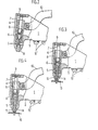
- Fig. 1 a front view partly in vertical section and showing the same with its handles fully opened;
- Fig. 2 a fragmentary sectional view partly broken away and showing the same with the upper handle slightly lowered by gravity, and
- Fig. 3 and Fic. 4 are views illustrating a blind rivet as inserted in place.
- Indicated at 1 is a hand riveter main body having a
lower handle 2. A tubularjas case housing 4, which is directed downward, is formed at the front end of ahead frame 3 included in the main body.Jaws 5, ajaw pusher 6 and aspring 7 for pressing the jaw pusher are inserted in this order in ajaw case 8, which is fitted in thehousing 4. The base end of thepressing spring 7 projecting outward from the upper end of thejaw case 8 bears against and is held by a closure member 9-in the form of a bored barrel and screwed in the upper end of thehousing 4. Theclosure member 9 is spaced from the upper end of thejaw case 8 by a required distance. Anupper handle 10 is pivoted at a boss portion to themain body 1. Thehandle 10 is formed at its front end with a bifurcatedportion 11 which is fittingly engaged inrecesses 12 formed at an upper portion of thejaw case 8 on the opposite sides of its outer periphery so that theupper handle 10, when moved upward or downward, advances or retracts thejaw case 8 within thehousing 4. With this arrangement, theupper handle 10 is biased by the force of the jawpusher pressing spring 7 so that thehandles nose piece 13 screwed inthe forward end of thehousing 4,interchangeable nose pieces 131 which are different in bore diameter and length, ablind rivet 14 andworkpieces 15 to be joined together. - When no consideration is given to the loweing of the
upper handle 10 which occurs under gravity depending on the position of the hand riveter of the above construction, the force of thespring 7 pressing thejaw pusher 6 fully acts on both the jaw members and theupper handle 10, advancing thejaw case 8 to cause thenose piece 13 to open thejaws 5 and also causing the jaw case to open thehandles upper handle 10 as seen in Fig. 1. Further when the hand riveter is held in the position in which gravity lowers theupper handle 10, theupper handle 10 slightly lowers under gravity against the force of thepressing spring 7, retracting thejaw case 8 to close thejaws 5 as shown in Fig. 2. - Accordingly the hand riveter is first held in the position of Fig. 1 so that the
upper handle 10 will not lower under gravity. Theblind rivet 14 can then be easily inserted through the jaw assembly because thejaws 5 are fully opened (see Fig. 3). When the hand riveter is subsequently so held that theupper handle 10, under gravity, suitably lowers against the force of thespring 7, thejaws 5 are closed to reliably grip theblind rivet 14 as shown in Fig.4. This eliminates the likelihood that the blind rivet will slip off the jaws, even when the riveter is used as directed downward for riveting, thus assuring the desired rivet setting operation. - As will be apparent from the above description, the present invention in which the spring for pressing the jaw pusher is used also for opening the handles eliminates the use of a spring for opening the handles to render the riveter simple in construction and inexpensive to make while completely overcoming the drawbacks of the two types of hand riveters described. The invention therefore assures a very smooth and easy rivet setting operation.
- In embodying this invention, the force of the pusher pressing spring is so determined that when the riveter is used for riveting, the upper handle will slightly lower under gravity against the force of the spring.
Claims (1)
- A hand riveter wherein a jaw case is movable forward and backward by opening and closing handles for setting rivets as desired, the hand riveter being characterized in that a closure member (9) for holding the base end of a spring (7) for pressing a jaw pusher (6) accommodated in the jaw case (8) is attached to an upper portion of a tubular jaw case housing (4) at a required distance from the jaw case (8),the handles being operable by the force of the pressing spring.
Applications Claiming Priority (2)
| Application Number | Priority Date | Filing Date | Title |
|---|---|---|---|
| JP6495/82U | 1982-01-20 | ||
| JP649582U JPS605960Y2 (en) | 1982-01-20 | 1982-01-20 | hand riveter |
Publications (1)
| Publication Number | Publication Date |
|---|---|
| EP0108835A1 true EP0108835A1 (en) | 1984-05-23 |
Family
ID=11640036
Family Applications (1)
| Application Number | Title | Priority Date | Filing Date |
|---|---|---|---|
| EP82201337A Withdrawn EP0108835A1 (en) | 1982-01-20 | 1982-10-25 | Hand riveter |
Country Status (3)
| Country | Link |
|---|---|
| EP (1) | EP0108835A1 (en) |
| JP (1) | JPS605960Y2 (en) |
| ES (1) | ES268389Y (en) |
Cited By (2)
| Publication number | Priority date | Publication date | Assignee | Title |
|---|---|---|---|---|
| EP2402095A1 (en) | 2010-07-01 | 2012-01-04 | BURY Sp. z o.o. | Universal blind rivet and threaded rivet nut setting system |
| CN105033150A (en) * | 2015-07-28 | 2015-11-11 | 德清恒鑫电子有限公司 | Press-riveting device |
Citations (4)
| Publication number | Priority date | Publication date | Assignee | Title |
|---|---|---|---|---|
| DE707582C (en) * | ||||
| FR1074497A (en) * | 1952-04-14 | 1954-10-06 | Wedge rivet and tool that can be used to set this rivet | |
| US3426572A (en) * | 1967-03-31 | 1969-02-11 | Celus Fasteners Inc | Rivet setting tool |
| US3760627A (en) * | 1971-12-13 | 1973-09-25 | Richline Co Inc | Rivet gun |
-
1982
- 1982-01-20 JP JP649582U patent/JPS605960Y2/en not_active Expired
- 1982-10-25 EP EP82201337A patent/EP0108835A1/en not_active Withdrawn
- 1982-11-08 ES ES1982268389U patent/ES268389Y/en not_active Expired
Patent Citations (4)
| Publication number | Priority date | Publication date | Assignee | Title |
|---|---|---|---|---|
| DE707582C (en) * | ||||
| FR1074497A (en) * | 1952-04-14 | 1954-10-06 | Wedge rivet and tool that can be used to set this rivet | |
| US3426572A (en) * | 1967-03-31 | 1969-02-11 | Celus Fasteners Inc | Rivet setting tool |
| US3760627A (en) * | 1971-12-13 | 1973-09-25 | Richline Co Inc | Rivet gun |
Cited By (2)
| Publication number | Priority date | Publication date | Assignee | Title |
|---|---|---|---|---|
| EP2402095A1 (en) | 2010-07-01 | 2012-01-04 | BURY Sp. z o.o. | Universal blind rivet and threaded rivet nut setting system |
| CN105033150A (en) * | 2015-07-28 | 2015-11-11 | 德清恒鑫电子有限公司 | Press-riveting device |
Also Published As
| Publication number | Publication date |
|---|---|
| ES268389Y (en) | 1983-12-01 |
| JPS58111142U (en) | 1983-07-29 |
| JPS605960Y2 (en) | 1985-02-25 |
| ES268389U (en) | 1983-05-16 |
Similar Documents
| Publication | Publication Date | Title |
|---|---|---|
| US4308770A (en) | Allen wrench handle | |
| US5335800A (en) | Magazine for rivet gun | |
| EP0081345A1 (en) | Hand held setting tool and method for setting deformable head fasteners | |
| ES461188A1 (en) | Automatic tool for setting rivets or like fasteners supplied in strip form | |
| WO2004012912A3 (en) | Handheld tool for breaking up rock | |
| US3374656A (en) | Tool for setting tubular rivets | |
| EP0108835A1 (en) | Hand riveter | |
| US3003657A (en) | Fastener-setting hand tool | |
| GB1376064A (en) | Rivet setting tool for blind rivets | |
| GB1116321A (en) | Improvements in or relating to blind-riveting tools | |
| US3785037A (en) | Hand tool for assembling open, bowed-body retaining rings having locking prongs in shaft or spindle grooves | |
| US3961517A (en) | Rivet setting tool | |
| US3626745A (en) | Rivet gun accessory | |
| US3426572A (en) | Rivet setting tool | |
| US3646800A (en) | Mandrel rivet-setting tool | |
| US2216767A (en) | Riveting tool | |
| US3326030A (en) | Manually operable tool for installing tubular rivets | |
| US3005566A (en) | Tool for installing hollow rivets | |
| US2909302A (en) | Riveting gun | |
| US5234147A (en) | Setting machine having moveable upper receiver | |
| JPS6178526A (en) | Jaw part structure of riveter | |
| US3711006A (en) | Nutplate installation device | |
| JP3433303B2 (en) | Riveter | |
| US5009556A (en) | Blind riveting nut | |
| SU598681A1 (en) | Chuck to riveting tool for setting single-side rivets |
Legal Events
| Date | Code | Title | Description |
|---|---|---|---|
| PUAI | Public reference made under article 153(3) epc to a published international application that has entered the european phase |
Free format text: ORIGINAL CODE: 0009012 |
|
| AK | Designated contracting states |
Designated state(s): AT BE CH DE FR GB IT LI LU NL SE |
|
| 17P | Request for examination filed |
Effective date: 19841108 |
|
| STAA | Information on the status of an ep patent application or granted ep patent |
Free format text: STATUS: THE APPLICATION IS DEEMED TO BE WITHDRAWN |
|
| 18D | Application deemed to be withdrawn |
Effective date: 19890404 |
|
| RIN1 | Information on inventor provided before grant (corrected) |
Inventor name: HOSODA, MASAHIRO |