EP0106985A2 - Operation monitoring of digital transmission links - Google Patents
Operation monitoring of digital transmission links Download PDFInfo
- Publication number
- EP0106985A2 EP0106985A2 EP83108586A EP83108586A EP0106985A2 EP 0106985 A2 EP0106985 A2 EP 0106985A2 EP 83108586 A EP83108586 A EP 83108586A EP 83108586 A EP83108586 A EP 83108586A EP 0106985 A2 EP0106985 A2 EP 0106985A2
- Authority
- EP
- European Patent Office
- Prior art keywords
- telemetry
- telegram
- telegrams
- signal
- shift register
- Prior art date
- Legal status (The legal status is an assumption and is not a legal conclusion. Google has not performed a legal analysis and makes no representation as to the accuracy of the status listed.)
- Granted
Links
Images
Classifications
-
- H—ELECTRICITY
- H04—ELECTRIC COMMUNICATION TECHNIQUE
- H04B—TRANSMISSION
- H04B17/00—Monitoring; Testing
- H04B17/40—Monitoring; Testing of relay systems
- H04B17/407—Monitoring; Testing of relay systems without selective localization
- H04B17/408—Monitoring; Testing of relay systems without selective localization using successive loop-backs
-
- H—ELECTRICITY
- H04—ELECTRIC COMMUNICATION TECHNIQUE
- H04B—TRANSMISSION
- H04B17/00—Monitoring; Testing
- H04B17/40—Monitoring; Testing of relay systems
- H04B17/401—Monitoring; Testing of relay systems with selective localization
Definitions
- the invention relates to a method for monitoring the operation of digital transmission links with intermediate regenerators arranged between two line terminals, in which a telemetry signal is transmitted via the same signal path as the digital signal, in which at least some of the intermediate regenerators contain telemetry units in which the transmitted telemetry signal is regenerated and amplified, and of which, in the first stinkre enerator g with telemetry unit, which no telemetry signal receives, from cyclically one consisting of several blocks of data telegram is sent, wherein the sequence of telegrams in the form of a telegram chain form the telemetry signal, in which the transmission of each subsequent telegram, the Telemetry unit of an intermediate regenerator is triggered by the receipt of at least one telegram from the line terminal or from the previous intermediate regenerator, in which self-monitoring of the intermediate regenerators is carried out
- the data blocks of the telegrams contain information about the state of the received digital signals and the function of the respective intermediate regenerator, in which the intermediate
- the monitoring signals can either be transmitted on a dedicated line or on the main signal. The latter type of transmission is preferred for planning and cost reasons. If the main and monitoring signals are transmitted on a common transmission medium, an adequate mutual signal-to-noise ratio must be ensured for both types of signal. Digital transmission systems with high bit rates may only have very small bit error rates of ⁇ 10 -10 bit errors per transmitted bit per regenerator field. The influence of the monitoring signal on the eye diagram at the decision threshold of the main signal must be correspondingly small. This means that the modulation spectrum of the monitoring signal has a negligible influence compared to the spectrum of the main signal. On the other hand, the proportionate spectrum of the Main signal be sufficiently small to ensure safe transmission of the monitoring signals.
- the sending line terminal also contains a telemetry transmitter, the receiving line terminal, which can be arranged at the far end of the line or can be identical to the sending line terminal, contains a telemetry unit. and a downstream locating device that stores, decrypts and displays all received monitoring signals.
- the telemetry transmitter sends a first telegram of a given word length in the sending line terminal with a subsequent closing character.
- the telemetry unit in the first intermediate regenerator receives this telegram, regenerates it and attaches its own telegram to the first and sends both out again.
- a telegram chain is created which is sent by the last telemetry unit in the receiving line terminal for evaluation to the locating device.
- the telegram chain in the receiving line terminal contains one more telegram than there are intermediate regenerators.
- the chronological assignment of the telegrams within the telegram chain corresponds to the sequence of the intermediate regenerators in the transmission direction or when a loop is formed from a specific telegram in the opposite direction.
- addressless telegrams in the locating device there is a clear assignment of the individual telegrams to the respective intermediate regenerators.
- the next telemetry unit begins after a predetermined waiting time to send its own telegram with the following closing characters.
- the telemetry units of the subsequent intermediate regenerators of the monitoring chain then behave as in the normal case, so that the telegram chain begins with the telegram of the intermediate regenerator that follows the faulty section.
- the telegram chain is now shortened by the number of intermediate regenerators located in front of the fault location, so that the fault location can be determined by counting the telegrams.
- the main information namely the information about the presence of a malfunction and the location of the fault
- the main information is the number of telegrams per chain at the receiving line terminal.
- the telegram contents are of minor importance in this regard, they normally serve to transmit discrete functional states of the individual intermediate regenerators to the locating device and relate to them Number of code rule violations, based on the bit rate, operating states of individual modules and information about the remote supply voltage or the transmission voltage of the main signal.
- the above-described method is sensitive to disturbances, particularly to so-called error bursts, so that considerable uncertainty about the actual fault location can result.
- the object of the invention is therefore to improve the interference immunity in a method of the type mentioned at the outset and also to provide an arrangement for carrying out the improved method.
- each of the telegrams in addition to the data blocks has at least one header identifier and an end identifier, that the header and end identifiers of the telegrams are identical to one another and form a time frame that the header and end identifiers of the telegrams in the receiving ones Telemetry units are monitored and a telegram is recognized as correct if the number of correctly received bits of the header and end identifiers exceeds a predefinable threshold value, that only correctly received telegrams are regenerated, amplified and delivered to the next section of the route in the order in which they were received that the associated telegram is suppressed when the specified threshold value is undershot and that a replacement telegram is inserted in its place in the telegram chain to be sent.
- the method according to the invention has the particular advantage of comparatively little effort in relation to the improvement in interference immunity achieved. Further developments of the method according to the invention are described in claims 2 and 3, an arrangement which is advantageous because of their structure in integrated technology for carrying out the method according to the invention is described in claims 4 to 6.
- a registration data input ME is connected to the first input E1, which acts as a series-parallel converter and contains data coding.
- a telemetry signal demodulator DEM and a telemetry signal decoder DEC are connected in succession to the telemetry signal input E2; the DEM telemetry signal demodulator is an AM demodulator, the DEC telemetry signal decoder converts the CD code (Conditioned Diphased) into a binary code.
- modulators or demodulators with FSK and PSK modulation are also used.
- the one output of the telemetry signal decoder is connected to an input of a central control ST, which is constructed as multiple logic.
- the binary signals are sent from a further output of the telemetry signal decoder to a first shifter gister SR1 output, the output of which is connected via a digital switch S to the input of a second shift register SR2.
- the output of this shift register is followed in series by a telemetry signal encoder for converting the binary signals into those in the CD code and a telemetry signal modulator in the form of an AM modulator to which the telemetry signal output of the telemetry unit is connected.
- the central controller ST is connected to a clock oscillator TO, which is constructed in the form of a phase-locked loop and which on the one hand outputs the generated clock signal to the central controller and on the other hand receives readjustment pulses from it.
- a clock oscillator TO which is constructed in the form of a phase-locked loop and which on the one hand outputs the generated clock signal to the central controller and on the other hand receives readjustment pulses from it.
- Two binary counters are connected in parallel to an output of the central control ST, the first serves as a frame counter RZ for counting the 28 bits from which a telegram is composed, while the other serves as a waiting time counter WZ counts a certain number of time units, after which one is lost
- the central control ST emits start pulses, by means of which the telemetry unit becomes a starter and emits the first telegram of a telegram chain.
- a frame and data checker RD On the output side, inputs of a frame and data checker RD are connected to the first and second shift registers SR1, SR2, which essentially contains AND gate logic and pass the test result on to an input of the central control ST via an output.
- the input of a frame renewer RE is connected, which is a set register, the parallel outputs of which are connected to the parallel inputs of the first and second shift registers SR1 and SR2, so that these inputs are output signals of the frame renewer RE can be activated and in the event of a telemetry fault a replacement telegram can be inserted.
- FIG. 2a shows the last, the penultimate and the first telegram Tn, Tn-1 and T1 of a telegram chain, which are constructed identically and each have a first and a second header password K1, K2, the actual data part and a first end password E1 contain.
- the header passwords K1 and K2 and the end password E1 were chosen with a length of 4 bits each, while the data part has a length of 16 bits and the length of the entire telegram thus results in 28 bits.
- the time for the transmission of a telegram is approximately 12 ms.
- the telegram chain has a cycle time of approximately 6.8 seconds with a maximum number of 512 telegrams and a corresponding number of final characters.
- the shift register arrangement according to FIG. 1 consisting of the first and second shift registers SR1, SR2 has a total of 32 shift register stages, so that a word with a length of 32 bits can be checked in each case. This makes it possible, in addition to an entire telegram include the first header password K1 of the next telegram or the final character E2, if it is the last telegram, in a single monitoring process.
- Such a word to be monitored with a bit length of 32 bits is shown schematically in the upper part of the following table.
- the frame recognizer and data checker RD in the exemplary embodiment is now organized in such a way that a telegram is recognized as correct if of the two head passwords, the first end password, the head password K1 of the next telegram or the final character E2 if it is the last telegram of the chain is about four individual characters, three correctly recognized.
- the frame counter RZ and the waiting time counter WZ are reset on the one hand via the central control ST, and on the other hand the frame renewer RE is activated, by means of which the two head passwords K1, K2 and the end password E1 in the shift register arrangement are renewed by parallel overwriting.
- the frame-renewed telegram is then read out and the next telegram is read into the shift register arrangement SR1, SR2, as shown in the table one after the other.
- a fault can now occur that after the frame counter RZ has expired, the frame of a subsequent telegram is not recognized according to the above criteria, since more than one of the header passwords is illegible and there is also no second final character E2.
- all 28 bits of the unrecognized telegram are overwritten by a replacement telegram in the shift register arrangement, this is also read out and the next telegram is read. For the duration of the fault, this continues until the frame recognition and data check the transition from the last telegram to the closing character, that is to say from the end password E1 to the final character E2 or, alternatively, a final character string in the cycle of the frame. counter RZ recognizes.
- the 28 final character bits immediately following the last telegram in the second shift register SR2 are overwritten in parallel by the operator's own telegram via the activation of the frame renewer RE and the registration data input ME and then also read out.
- the frame recognizer and data checker RD also checks whether the frame renewal of other telegrams and the insertion of the frame and the reporting data of the own telegram into the shift register SR2 was carried out correctly. If the test result is negative, the reading is stopped so that the telemetry unit stops sending its telemetry signals. This ensures that the telemetry unit only transmits telegrams with the correct frame and with its own telegram also with correct data to the next telemetry unit.
- the absence of telemetry signals is interpreted as a malfunction in the next telemetry unit.
- the waiting time counter WZ causes the central control ST to change over to the so-called "starter mode" after the waiting time has expired. This is shown as the second operating state in the table.
- the telemetry unit starts then with the transmission of its own telegram with the following final character E2 in time with the cycle time of the telegram chain Tk, but during such a cycle the fault in the previous transmission section can be remedied, so that the telemetry unit effective as a starter suddenly receives telemetry signals from the previous telemetry unit again.
- the entire shift register arrangement is subdivided into a first shift register SR1 with four stages and a second shift register SR2 with 28 stages by an interposed digital switch S.
- the two shift registers are separated by the digital switch S which is open in this case.
- the second shift register SR2 is then used to send out its own telegram followed by the final character 32, while the first shift register SR1, clocked by the asynchronous clock of the decoder DEC, is still available for reading in possible new telegrams. If the frame recognizer and data tester RD now recognizes the first or second header password K1, K2, the central control ST is switched over and the starter operation is thus interrupted.
- the digital switch S is closed to the second shift register SR2 and the incoming telegram is read into the second shift register with the clock of the decoder.
- the clock oscillator TO which is constructed as a phase locked loop, is re-synchronized via the decoder clock. If the frame recognizer and data checker RD recognizes the frame of the telegram according to the criteria already explained, then the central control ST is caused to switch back from the starter to normal operation. Normal operation then runs in the manner already described.
- the frame recognizer and data checker RD recognizes the frame within 28 bits during the synchronization state however, the telemetry unit does not remain in starter mode.
- the digital switch S between the two shift registers is opened again and the clock oscillator TO is returned to its mean oscillation frequency. and the transmission of the own telegram with subsequent final characters is continued with the aid of the separated second shift register in the cycle time cycle.
- the operating state "starter" of the telemetry unit is, due to the described processes, the inevitable consequence of the non-detection of telegram frames after the waiting time has expired.
- the waiting time was therefore chosen to be twice the cycle time; The telemetry unit thus only returns to normal operation, and from one bit to the next, if it has correctly recognized the frame of an incoming telegram according to the criteria mentioned. This ensures that normal operation due to simulated telemetry data is largely prevented.
- the exemplary embodiment could be implemented by means of integrated C-MOS modules, the transmission rate of the digital telemetry signals being 2.4 kbit / s and the maximum permissible rate of registration data at the first input E1 being approximately 3 Mbit / s.
Abstract
Description
Die Erfindung betrifft ein Verfahren zur Betriebsüberwachung digitaler Übertragungsstrecken mit zwischen zwei Leitungsendgeräten angeordneten Zwischenregeneratoren, bei dem ein Telemetriesignal über den gleichen Signalweg wie das digitale Signal übertragen wird, bei dem wenigstens einige der Zwischenregeneratoren Telemetrieeinheiten enthalten, in denen das übertragene Telemetriesignal regeneriert und verstärkt wird und von denen, beim ersten Zwischenregenerator mit Telemetrieeinheit, der kein Telemetriesignal empfängt, angefangen, zyklisch ein aus mehreren Datenblöcken bestehendes Telegramm ausgesendet wird, bei dem die Folge der Telegramme in Form einer Telegrammkette das Telemetriesignal bildet, bei dem die Aussendung jedes anschließenden Telegramms der Telemetrieeinheit eines Zwischenregenerators durch den Empfang wenigstens eines Telegramms vom Leitungsendgerät oder vom vorhergehenden Zwischenregenerator ausgelöst wird, bei dem eine Eigenüberwachung der Zwischenregeneratoren durchgeführt wird und als Ergebnis dieser Überwachung die Datenblöcke der Telegramme Informationen über den Zustand der empfangenen digitalen Signale und die Funktion des jeweiligen Zwischenregenerators enthalten, bei dem im Ortungsgerät des empfangsseitigen Leitungsendgerätes die Zwischenregeneratoren durch Auszählen der Telemetriesignale lokalisiert werden und die verschiedenen Streckenabschnitte und Zwischenregeneratoren durch Auswerten der Datenblöcke der Telemetriesignale überwacht werden, und eine Anordnung zur Durchführung des erfindungsgemäßen Verfahrens.The invention relates to a method for monitoring the operation of digital transmission links with intermediate regenerators arranged between two line terminals, in which a telemetry signal is transmitted via the same signal path as the digital signal, in which at least some of the intermediate regenerators contain telemetry units in which the transmitted telemetry signal is regenerated and amplified, and of which, in the first Zwischenre enerator g with telemetry unit, which no telemetry signal receives, from cyclically one consisting of several blocks of data telegram is sent, wherein the sequence of telegrams in the form of a telegram chain form the telemetry signal, in which the transmission of each subsequent telegram, the Telemetry unit of an intermediate regenerator is triggered by the receipt of at least one telegram from the line terminal or from the previous intermediate regenerator, in which self-monitoring of the intermediate regenerators is carried out As a result of this monitoring, the data blocks of the telegrams contain information about the state of the received digital signals and the function of the respective intermediate regenerator, in which the intermediate regenerators are located in the locating device of the receiving-side line terminal by counting the telemetry signals and the various route sections and intermediate regenerators by evaluation of the data blocks of the telemetry signals are monitored, and an arrangement for carrying out the method according to the invention.
Bei digitalen Übertragungssystemen hoher Bitrate auf Koaxialkabeln und Lichtwellenleitern ist die überbrückbare Leitungslänge begrenzt. Zwischen zwei Endstellen, bei Koaxialkabeln gleichzeitig den fernspeisenden, ist daher eine große Zahl von bis zu einigen hundert Zwischenregeneratoren eingefügt. Zur Gewährleistung der Betriebssicherheit ist eine laufende Überwachung der digitalen Übertragungsstrecke und damit der Leitungsendgeräte und aller Zwischenregeneratoren während des Betriebs erwünscht. Diese Aufgabe übernimmt ein sogenanntes Betriebsüberwachungssystem, das die Funktionszustände der über die Strecke verteilten Zwischenregeneratoren an die in Übertragungsrichtung ferne Endstelle übermittelt, es besteht auch die Möglichkeit, durch Bildung einer Schleife in der fernen Endstelle oder den Zwischenstellen die Funktionszustände der Zwischenregeneratoren beider Übertragungsrichtungen zu einer überwachenden Endstelle am Streckenanfang oder -ende zu übermitteln. Die Übertragung der Überwachungssignale kann entweder auf einer eigenen Leitung oder auf der des Hauptsignals erfolgen. Aus Planungs- und Kostengründen wird letzterer Übertragungsart der Vorzug gegeben. Erfolgt die Übertragung der Haupt- und Überwachungssignale auf einem gemeinsamen Übertragungsmedium, ist für einen ausreichenden gegenseitigen Störabstand beider Signalarten zu sorgen. Digitale Übertragungssysteme hoher Bitraten dürfen nur sehr kleine Bitfehlerraten von < 10-10 Bitfehler pro übertragenes Bit je Regeneratorfeld aufweisen. Entsprechend gering muß der Einfluß des Überwachungssignals auf das Augendiagramm an der Entscheiderschwelle des Hauptsignals sein. Dies bedingt, daß das Modulationsspektrum des Überwachungssignals gegenüber dem Spektrum des Hauptsignals von vernachlässigbarem Einfluß ist. Andererseits muß aber auch innerhalb der Bandbreite des Überwachungssignals das anteilige Spektrum des Hauptsignals ausreichend klein sein, um eine sichere Übertragung der Überwachungssignale zu gewährleisten. Die einander widersprechenden Forderungen bedingen zu ihrer Erfüllung ein entsprechend weites Auseinanderrücken beider Übertragungsspektren, oder wenn dies aus Übertragungsgründen nicht möglich ist, z.B. wegen der bandbegrenzenden Übertragungseigenschaften der Fernspeiseweichen, einen entsprechend hohen Aufwand an Filter- und Entzerrungsmitteln.In the case of digital transmission systems with a high bit rate on coaxial cables and optical fibers, the cable length that can be bridged is limited. A large number of up to a few hundred intermediate regenerators is therefore inserted between two end points, in the case of coaxial cables simultaneously the remote feeders. To ensure operational safety, continuous monitoring of the digital transmission path and thus the line terminals and all intermediate regenerators is desirable during operation. This task is carried out by a so-called operational monitoring system, which transmits the functional states of the intermediate regenerators distributed over the route to the end station remote in the direction of transmission; it is also possible to monitor the functional states of the intermediate regenerators in both transmission directions by forming a loop in the distant end station or the intermediate stations To transmit the end point at the beginning or end of the route. The monitoring signals can either be transmitted on a dedicated line or on the main signal. The latter type of transmission is preferred for planning and cost reasons. If the main and monitoring signals are transmitted on a common transmission medium, an adequate mutual signal-to-noise ratio must be ensured for both types of signal. Digital transmission systems with high bit rates may only have very small bit error rates of <10 -10 bit errors per transmitted bit per regenerator field. The influence of the monitoring signal on the eye diagram at the decision threshold of the main signal must be correspondingly small. This means that the modulation spectrum of the monitoring signal has a negligible influence compared to the spectrum of the main signal. On the other hand, the proportionate spectrum of the Main signal be sufficiently small to ensure safe transmission of the monitoring signals. The contradicting requirements require a correspondingly wide separation of both transmission spectra to meet them, or if this is not possible for transmission reasons, e.g. due to the band-limiting transmission properties of the remote feeders, a correspondingly high level of filter and equalization means.
Aus der DE-OS 30 27 755 ist ein adressenloses Telemetrieverfahren der eingangs erwähnten Art bekannt. Dieses Verfahren setzt eine Telemetrieeinheit in jedem Zwischenregenerator voraus, die einen Telemetriesignal-Regenerator und einen Telemetriesignalsender enthält. Die Aus- und Einspeisung der Überwachungssignale zur und von der Telemetrieeinheit in den Übertragungsweg des Hauptsignals erfolgt dabei über Aus- und Einkoppeleinrichtungen am Eingang und am Ausgang des jeweiligen Zwischenregenerators.From DE-OS 30 27 755 an addressless telemetry method of the type mentioned is known. This method requires a telemetry unit in each intermediate regenerator, which contains a telemetry signal regenerator and a telemetry signal transmitter. The monitoring signals are fed in and out to and from the telemetry unit in the transmission path of the main signal via coupling and decoupling devices at the input and output of the respective intermediate regenerator.
Das sendende Leitungsendgerät enthält ebenfalls einen Telemetriesender, das empfangende Leitungsendgerät, das am fernen Leitungsende angeordnet sein kann oder mit dem sendenden Leitungsendgerät identisch sein kann, enthält eine Telemetrieeinheit. und ein nachgeschaltetes Ortungsgerät, das sämtliche empfangenen Überwachungssignale speichert, dechiffriert und anzeigt. Zu Beginn der Übertragung sendet der Telemetriesender im sendenden Leitungsendgerät ein erstes Telegramm vorgegebener Wortlänge mit nachfongendem Schlußzeichen aus. Die Telemetrieeinheit im ersten Zwischenregenerator empfängt dieses Telegramm, regeneriert es und hängt ihr eigenes Telegramm an das erste an und sendet beide wieder aus. Bei der Weitergabe der Telegramme zu den einzelnen Zwischenregeneratoren entsteht so eine Telegrammkette, die von der letzten Telemetrieeinheit im empfangenden Leitungsendgerät zur Auswertung an das Ortungsgerät abgegeben wird. Im Normalfall enthält damit die Telegrammkette im empfangenden Leitungsendgerät ein Telegramm mehr als Zwischenregeneratoren vorhanden sind. Die zeitliche Zuordnung der Telegramme innerhalb der Telegrammkette entspricht der Reihenfolge der Zwischenregeneratoren in der Übertragungsrichtung bzw. bei der Bildung einer Schleife ab einem bestimmten Telegramm in Gegenrichtung. So ist trotz adressenloser Telegramme im Ortungsgerät eine eindeutige Zuordnung der einzelnen Telegramme zu den jeweiligen Zwischenregeneratoren gegeben.The sending line terminal also contains a telemetry transmitter, the receiving line terminal, which can be arranged at the far end of the line or can be identical to the sending line terminal, contains a telemetry unit. and a downstream locating device that stores, decrypts and displays all received monitoring signals. At the beginning of the transmission, the telemetry transmitter sends a first telegram of a given word length in the sending line terminal with a subsequent closing character. The telemetry unit in the first intermediate regenerator receives this telegram, regenerates it and attaches its own telegram to the first and sends both out again. When the telegrams are passed on to the individual intermediate regenerators, a telegram chain is created which is sent by the last telemetry unit in the receiving line terminal for evaluation to the locating device. Normally, the telegram chain in the receiving line terminal contains one more telegram than there are intermediate regenerators. The chronological assignment of the telegrams within the telegram chain corresponds to the sequence of the intermediate regenerators in the transmission direction or when a loop is formed from a specific telegram in the opposite direction. Despite addressless telegrams in the locating device, there is a clear assignment of the individual telegrams to the respective intermediate regenerators.
Tritt im Übertragungsweg eine Störung auf, die zu einer Unterbrechung der Telemetriesignalübertragung führt, beginnt die nächstfolgende Telemetrieeinheit nach einer vorgegebenen Wartezeit von sich aus mit dem Aussenden des eigenen Telegramms mit nachfolgenden Schlußzeichen. Die Telemetrieeinheiten der nachfolgenden Zwischenregeneratoren der Überwachungskette verhalten sich daraufhin so wie im Regelfall, so daß die Telegrammkette mit dem Telegramm des Zwischenregenerators beginnt, der auf den gestörten Abschnitt folgt. Die Telegrammkette ist nun um die Zahl der vor der Störungsstelle befindlichen Zwischenregeneratoren verkürzt, so daß durch Abzählen der Telegramme der Störungsort bestimmbar ist.If a malfunction occurs in the transmission path, which leads to an interruption in the telemetry signal transmission, the next telemetry unit begins after a predetermined waiting time to send its own telegram with the following closing characters. The telemetry units of the subsequent intermediate regenerators of the monitoring chain then behave as in the normal case, so that the telegram chain begins with the telegram of the intermediate regenerator that follows the faulty section. The telegram chain is now shortened by the number of intermediate regenerators located in front of the fault location, so that the fault location can be determined by counting the telegrams.
Bei dem erläuterten Uberwachungsverfahren liegt die Hauptinformation, nämlich die Information über das Vorliegen einer Betriebsstörung und den Störungsort in der Anzahl der Telegramme je Kette am empfangenden Leitungsendgerät. Die Telegramminhalte sind diesbezüglich von untergeordneter Bedeutung, sie dienen im Normalfall der Übermittlung diskreter Funktionszustände der einzelnen Zwischenregeneratoren an das Ortungsgerät und betreffen Anzahl der Coderegelverletzungen, bezogen auf die Bitrate, Betriebszustände einzelner Baugruppen und Informationen über die Fernspeisespannung bzw. die Sendespannung des Hauptsignals.In the monitoring method explained, the main information, namely the information about the presence of a malfunction and the location of the fault, is the number of telegrams per chain at the receiving line terminal. The telegram contents are of minor importance in this regard, they normally serve to transmit discrete functional states of the individual intermediate regenerators to the locating device and relate to them Number of code rule violations, based on the bit rate, operating states of individual modules and information about the remote supply voltage or the transmission voltage of the main signal.
Bei der eingangs erwähnten großen Anzahl von bis zu mehreren 100 Zwischenregeneratoren pro Übertragungsstrecke und einer entsprechend langen Telegrammkette ist das vorstehend geschilderte Verfahren empfindlich gegen Störungen, besonders gegen sogenannte Fehlerbursts, so daß sich eine erhebliche Unsicherheit über den tatsächlichen Störungsort ergeben kann.Given the large number of up to several hundred intermediate regenerators per transmission link and a correspondingly long telegram chain mentioned above, the above-described method is sensitive to disturbances, particularly to so-called error bursts, so that considerable uncertainty about the actual fault location can result.
Die Aufgabe der Erfindung besteht also darin, bei einem Verfahren der eingangs erwähnten Art die Störsicherheit zu verbessern und außerdem eine Anordnung zur Durchführung des verbesserten Verfahrens anzugeben.The object of the invention is therefore to improve the interference immunity in a method of the type mentioned at the outset and also to provide an arrangement for carrying out the improved method.
Erfindungsgemäß wird die Aufgabe dadurch gelöst, daß jedes der Telegramme neben den Datenblöcken wenigstens eine Kopfkennung und eine Endekennung aufweist, daß die Kopf- und die Endekennungen der Telegramme untereinander gleich sind und einen Zeitrahmen bilden, daß die Kopf-und Endekennungen der Telegramme in den empfangenden Telemetrieeinheiten überwacht werden und ein Telegramm dann als richtig erkannt gilt, wenn die Anzahl der richtig empfangenen Bits der Kopf- und der Endekennungen einen vorgebbaren Schwellenwert überschreitet, daß nur richtig empfangene Telegramme in der Reihenfolge ihres Empfanges regeneriert, verstärkt und an den nächsten Streckenabschnitt abgegeben werden, daß bei Unterschreiten des vorgegebenen Schwellenwertes das zugehörige Telegramm unterdrückt und daß an dessen Stelle ein Ersatztelegramm in die auszusendende Telegrammkette eingeblendet wird. Das erfindungsgemäße Verfahren hat den besonderen Vorteil des vergleichweise geringen Aufwandes im Verhältnis zur erreichten Verbesserung der Störsicherheit. Weiterbildungen des erfindungsgemäßen Verfahrens sind in den Patentansprüchen 2 und 3 beschrieben, eine wegen ihres Aufbaus in integrierter Technik vorteilhafte Anordnung zur Durchführung des erfindungsgemäßen Verfahrens ist in den Patentansprüchen 4 bis 6 beschrieben.According to the invention the object is achieved in that each of the telegrams in addition to the data blocks has at least one header identifier and an end identifier, that the header and end identifiers of the telegrams are identical to one another and form a time frame that the header and end identifiers of the telegrams in the receiving ones Telemetry units are monitored and a telegram is recognized as correct if the number of correctly received bits of the header and end identifiers exceeds a predefinable threshold value, that only correctly received telegrams are regenerated, amplified and delivered to the next section of the route in the order in which they were received that the associated telegram is suppressed when the specified threshold value is undershot and that a replacement telegram is inserted in its place in the telegram chain to be sent. The method according to the invention has the particular advantage of comparatively little effort in relation to the improvement in interference immunity achieved. Further developments of the method according to the invention are described in claims 2 and 3, an arrangement which is advantageous because of their structure in integrated technology for carrying out the method according to the invention is described in claims 4 to 6.
Die Erfindung soll im folgenden anhand der Zeichnung näher erläutert werden. In der Zeichnung zeigt
- Fig. 1 den prinzipiellen Aufbau einer.Telemetrieeinheit und
- Fig. 2 den Aufbau der übertragenen Telegramme und einer Telegrammkette.
- Fig. 1 shows the basic structure of a telemetry unit and
- Fig. 2 shows the structure of the transmitted telegrams and a telegram chain.
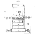
Die Telemetrieeinheit nach der Fig. 1 weist einen ersten Eingang E1 auf, an den der Meldedatengeber des Zwischenregenerators angeschlossen ist, sowie einen zweiten Eingang E2, an dem das im Signalweg mitübertragene Telemetriesignal der vorhergehenden Zwischenregeneratoren ansteht. An den ersten Eingang E1 ist eine Meldedateneingabe ME angeschlossen, die als Serien-Parallel-Wandler fungiert und eine Datencodierung enthält. An den Telemetriesignaleingang E2 sind nacheinander ein Telemetriesignal-Demodulator DEM und ein Telemetriesignal- Decoder DEC angeschlossen; beim Telemetriesignal-Demodulator DEM handelt es sich um einen AM-Demodulator, im Telemetriesignal-Decoder DEC findet eine Umwandlung vom CD-Code (Conditioned Diphased-) in einen Binärcode statt. Bei anderen Ausführungsbeispielen werden auch Modulatoren bzw. Demodulatoren mit FSK-und PSK-Modulation verwendet. Mit dem einen Ausgang des Telemetriesignal-Decoders ist ein Eingang einer zentralen Steuerung ST verbunden, die als Mehrfachlogik aufgebaut ist. Von einem weiteren Ausgang des Telemetriesignal-Decoders werden die Binärsignale an ein erstes Schieberegister SR1 abgegeben, dessen Ausgang über einen digitalen Schalter S mit dem Eingang eines zweiten Schieberegisters SR2 verbunden ist. An den Ausgang dieses Schieberegisters schließen sich in Reihe ein Telemetriesignal-Codierer zur Umwandlung der Binärsignale in solche im CD-Code und ein Telemetriesignal-Modulator in Form eines AM-Modulators an, an den der Telemetriesignalausgang der Telemetrieeinheit angeschlossen ist.1 has a first input E1 to which the reporting data transmitter of the intermediate regenerator is connected, and a second input E2 to which the telemetry signal of the previous intermediate regenerators transmitted in the signal path is present. A registration data input ME is connected to the first input E1, which acts as a series-parallel converter and contains data coding. A telemetry signal demodulator DEM and a telemetry signal decoder DEC are connected in succession to the telemetry signal input E2; the DEM telemetry signal demodulator is an AM demodulator, the DEC telemetry signal decoder converts the CD code (Conditioned Diphased) into a binary code. In other exemplary embodiments, modulators or demodulators with FSK and PSK modulation are also used. The one output of the telemetry signal decoder is connected to an input of a central control ST, which is constructed as multiple logic. The binary signals are sent from a further output of the telemetry signal decoder to a first shifter gister SR1 output, the output of which is connected via a digital switch S to the input of a second shift register SR2. The output of this shift register is followed in series by a telemetry signal encoder for converting the binary signals into those in the CD code and a telemetry signal modulator in the form of an AM modulator to which the telemetry signal output of the telemetry unit is connected.
Die zentrale Steuerung ST ist mit einem Taktoszillator TO verbunden, der in Form einer Phasenregelschleife aufgebaut ist und der einerseits an die zentrale Steuerung das erzeugte Taktsignal abgibt und andererseits von dieser Nachsteuerungsimpulse erhält. An einen Ausgang der zentralen Steuerung ST sind parallel zwei Binärzähler angeschlossen, der erste dient als Rahmenzähler RZ zur Zählung der 28 Bit, aus denen sich ein Telegramm zusammensetzt, während der andere als Wartezeitzähler WZ eine bestimmte Anzahl von Zeiteinheiten zählt, nach denen bei Wegfall eines Ausgangssignals am Telemetriesignal-Decoder DEC die zentrale Steuerung ST Startimpulse abgibt, durch die die Telemetrieeinheit zum Starter wird und das erste Telegramm einer Telegrammkette abgibt. Mit dem ersten und dem zweiten Schieberegister SR1, SR2 sind ausgangsseitig Eingänge eines Rahmen- und Datenprüfers RD verbunden, der im wesentlichen eine UND-Gatterlogik enthält und das Prüfungsergebnis über einen Ausgang an einen Eingang der zentralen Steuerung ST weiterletiet. Mit einem weiteren Ausgang der zentralen Steuerung ST ist der Eingang eines Rahmenerneuerers RE verbunden, bei dem es sich um ein gesetztes Register handelt, dessen Parallelausgänge mit den Paralleleingängen des ersten und des zweiten'Schieberegisters SR1 und SR2 verbunden sind, so daß diese Eingänge durch Ausgangssignale des Rahmenerneuerers RE aktiviert werden können und bei einer Störung der Telemetriesignalübertragung ein Ersatztelegramm eingefügt werden kann.The central controller ST is connected to a clock oscillator TO, which is constructed in the form of a phase-locked loop and which on the one hand outputs the generated clock signal to the central controller and on the other hand receives readjustment pulses from it. Two binary counters are connected in parallel to an output of the central control ST, the first serves as a frame counter RZ for counting the 28 bits from which a telegram is composed, while the other serves as a waiting time counter WZ counts a certain number of time units, after which one is lost Output signal at the telemetry signal decoder DEC, the central control ST emits start pulses, by means of which the telemetry unit becomes a starter and emits the first telegram of a telegram chain. On the output side, inputs of a frame and data checker RD are connected to the first and second shift registers SR1, SR2, which essentially contains AND gate logic and pass the test result on to an input of the central control ST via an output. With another output of the central control ST, the input of a frame renewer RE is connected, which is a set register, the parallel outputs of which are connected to the parallel inputs of the first and second shift registers SR1 and SR2, so that these inputs are output signals of the frame renewer RE can be activated and in the event of a telemetry fault a replacement telegram can be inserted.
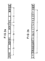
Der Aufbau der übermittelten Telegramme in sich und die Kombination in einer Telegrammkette Tk ist in der Fig. 2 erläutert. In der Fig. 2a sind das letzte, das vorletzte und das erste Telegramm Tn, Tn-1 und T1 einer Telegrammkette dargestellt, die gleich aufgebaut sind und jeweils ein erstes und ein zweites Kopfkennwort K1, K2, den eigentlichen Datenteil und ein erstes Endekennwort E1 enthalten. Im vorliegenden Falle wurden die Kopfkennworte K1 und K2 sowie das Endekennwort E1 mit einer Länge von je 4 Bit gewählt, während der Datenteil eine Länge von 16 Bit umfaßt und die Länge des gesamten Telegramms sich damit zu 28 Bit ergibt. Im Hinblick auf die gewählte Übertragungsgeschwindigkeit von 2,4 kBit/s ergibt sich damit die Zeitdauer für die Übermittlung eines Telegramms zu etwa 12 ms.The structure of the transmitted telegrams in itself and the combination in a telegram chain Tk is explained in FIG. 2. 2a shows the last, the penultimate and the first telegram Tn, Tn-1 and T1 of a telegram chain, which are constructed identically and each have a first and a second header password K1, K2, the actual data part and a first end password E1 contain. In the present case, the header passwords K1 and K2 and the end password E1 were chosen with a length of 4 bits each, while the data part has a length of 16 bits and the length of the entire telegram thus results in 28 bits. With regard to the selected transmission speed of 2.4 kbit / s, the time for the transmission of a telegram is approximately 12 ms.
In der Fig. 2b ist eine vollständige Telegrammkette dargestellt, die neben den aufeinanderfolgenden Einzeltelegrammen als Füllzeichen eine Anzahl zweiter Endekennwörter E2 enthält. Diese zweiten Endekennwörter stellen gleichzeitig das Schlußzeichen der Telegrammkette dar, bei deren Empfang eine Rückstellung des entsprechenden Ortungsgerätes erfolgt. Die Telegrammkette weist im Ausführungsbeispiel bei einer maximalen Anzahl von 512 Telegrammen und einer entsprechenden Anzahl an Schlußzeichen eine Zykluszeit von etwa 6,8 sec auf.2b shows a complete telegram chain which, in addition to the successive individual telegrams, contains a number of second end passwords E2 as filler characters. These second end passwords simultaneously represent the final character of the telegram chain, upon receipt of which the corresponding locating device is reset. In the exemplary embodiment, the telegram chain has a cycle time of approximately 6.8 seconds with a maximum number of 512 telegrams and a corresponding number of final characters.
Die aus den ersten und zweiten Schieberegistern SR1, SR2 bestehende Schieberegisteranordnung nach der Fig. 1 weist insgesamt 32 Schieberegisterstufen auf, so daß ein Wort mit einer Länge von 32 Bit jeweils überprüft werden kann. Damit ist es möglich, neben einem gesamten Telegramm auch das erste Kopfkennwort K1 des nächsten Telegramms oder das Schlußzeichen E2, wenn es sich um'das letzte Telegramm handelt, in einen einzelnen Überwachungsvorgang einzubeziehen.The shift register arrangement according to FIG. 1 consisting of the first and second shift registers SR1, SR2 has a total of 32 shift register stages, so that a word with a length of 32 bits can be checked in each case. This makes it possible, in addition to an entire telegram include the first header password K1 of the next telegram or the final character E2, if it is the last telegram, in a single monitoring process.
In der nachfolgenden Tabelle ist im oberen Teil schematisch ein derartiges zu überwachendes Wort mit einer,Bit- länge von 32 Bit dargestellt.
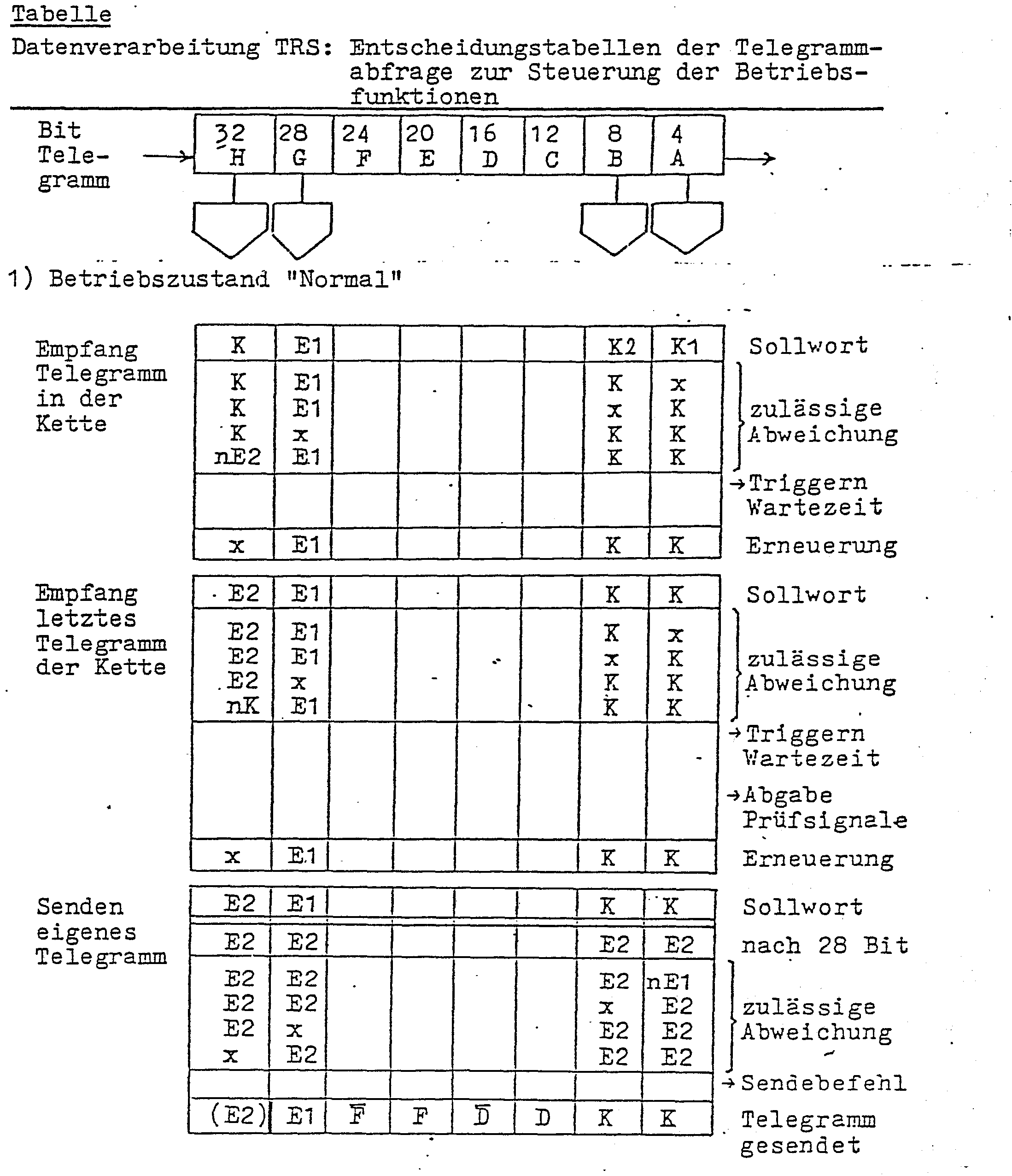
Entsprechend der Tabelle ist nun der Rahmenerkenner und Datenprüfer RD im Ausführungsbeispiel so organisiert, daß ein Telegramm dann als richtig erkannt gilt, wenn von den beiden Kopfkennworten, dem ersten Endekennwort, dem Kopfkennwort K1 des nächsten Telegramms oder dem'Schlußzeichen E2, falls es sich um das letzte Telegramm der Kette handelt, also von vier einzelnen Zeichen, drei richtig erkannt werden. In diesem Fall wird zum einen über die zentrale Steuerung ST der Rahmenzähler RZ und der Wartezeitzähler WZ zurückgesetzt, zum andern der Rahmenerneuerer RE aktiviert, durch den die beiden Kopfkennworte K1, K2 und das Endekennwort E1 in der Schieberegisteranordnung durch paralleles Überschreiben erneuert werden. Danach wird das rahmenerneuerte Telegramm ausgelesen und das nächste Telegramm in die Schieberegisteranordnung SR1, SR2 eingelesen, wie dies in der Tabelle nacheinander dargestellt ist.According to the table, the frame recognizer and data checker RD in the exemplary embodiment is now organized in such a way that a telegram is recognized as correct if of the two head passwords, the first end password, the head password K1 of the next telegram or the final character E2 if it is the last telegram of the chain is about four individual characters, three correctly recognized. In this case, the frame counter RZ and the waiting time counter WZ are reset on the one hand via the central control ST, and on the other hand the frame renewer RE is activated, by means of which the two head passwords K1, K2 and the end password E1 in the shift register arrangement are renewed by parallel overwriting. The frame-renewed telegram is then read out and the next telegram is read into the shift register arrangement SR1, SR2, as shown in the table one after the other.
Durch eine Störung kann nun der Fall eintreten, daß nach Ablauf des Rahmenzählers RZ der Rahmen eines folgenden Telegramms nach den obigen Kriterien nicht erkannt wird, da mehr als eines der Kopfkennworte unleserlich ist und auch kein zweites Schlußzeichen E2 auftritt. In diesem Falle werden alle 28 Bit des nicht erkannten Telegramms durch ein Ersatztelegramm in der Schieberegisteranordnung überschrieben, diese gleichfalls aus- und das nächste Telegramm eingelesen. Für die Dauer der Störung wird dies fortgesetzt, bis die Rahmenerkennung und Datenprüfung den Übergang vom letzten Telegramm zum Schlußzeichen,also vom Endekennwort E1 zum Schlußzeicnen E2 oder ersatzweise eine Schlußzeichenfolge im Takte des Rahmen-. zählers RZ erkennt. Ist dies der Fall, dann werden die unmittelbar dem letzten Telegramm folgenden 28 Schlußzeichenbits im zweiten Schieberegister SR2 durch das eigene Telegramm über die Aktivierung des Rahmenerneuerers RE und der Meldedateneingabe ME parallel überschrieben und danach ebenfalls ausgelesen. Außerdem prüft der Rahmenerkenner und Datenprüfer RD vor dem Auslesen, ob die Rahmenerneuerung fremder Telegramme und das Einsetzen des Rahmens und der Meldedaten des eigenen Telegramms in-das Schieberegister SR2 korrekt erfolgte. Bei negativem Prüfungsergebnis wird das Auslesen gestoppt, so daß die Telemetrieeinheit die Aussendung ihrer Telemetriesignale einstellt. Damit ist sichergestellt, daß die Telemetrieeinheit nur Telegramme mit korrektem Rahmen und beim eigenen Telegramm zusätzlich mit korrekten Daten an die nächste Telemetrieeinheit weitergibt.A fault can now occur that after the frame counter RZ has expired, the frame of a subsequent telegram is not recognized according to the above criteria, since more than one of the header passwords is illegible and there is also no second final character E2. In this case, all 28 bits of the unrecognized telegram are overwritten by a replacement telegram in the shift register arrangement, this is also read out and the next telegram is read. For the duration of the fault, this continues until the frame recognition and data check the transition from the last telegram to the closing character, that is to say from the end password E1 to the final character E2 or, alternatively, a final character string in the cycle of the frame. counter RZ recognizes. If this is the case, then the 28 final character bits immediately following the last telegram in the second shift register SR2 are overwritten in parallel by the operator's own telegram via the activation of the frame renewer RE and the registration data input ME and then also read out. Before reading out, the frame recognizer and data checker RD also checks whether the frame renewal of other telegrams and the insertion of the frame and the reporting data of the own telegram into the shift register SR2 was carried out correctly. If the test result is negative, the reading is stopped so that the telemetry unit stops sending its telemetry signals. This ensures that the telemetry unit only transmits telegrams with the correct frame and with its own telegram also with correct data to the next telemetry unit.
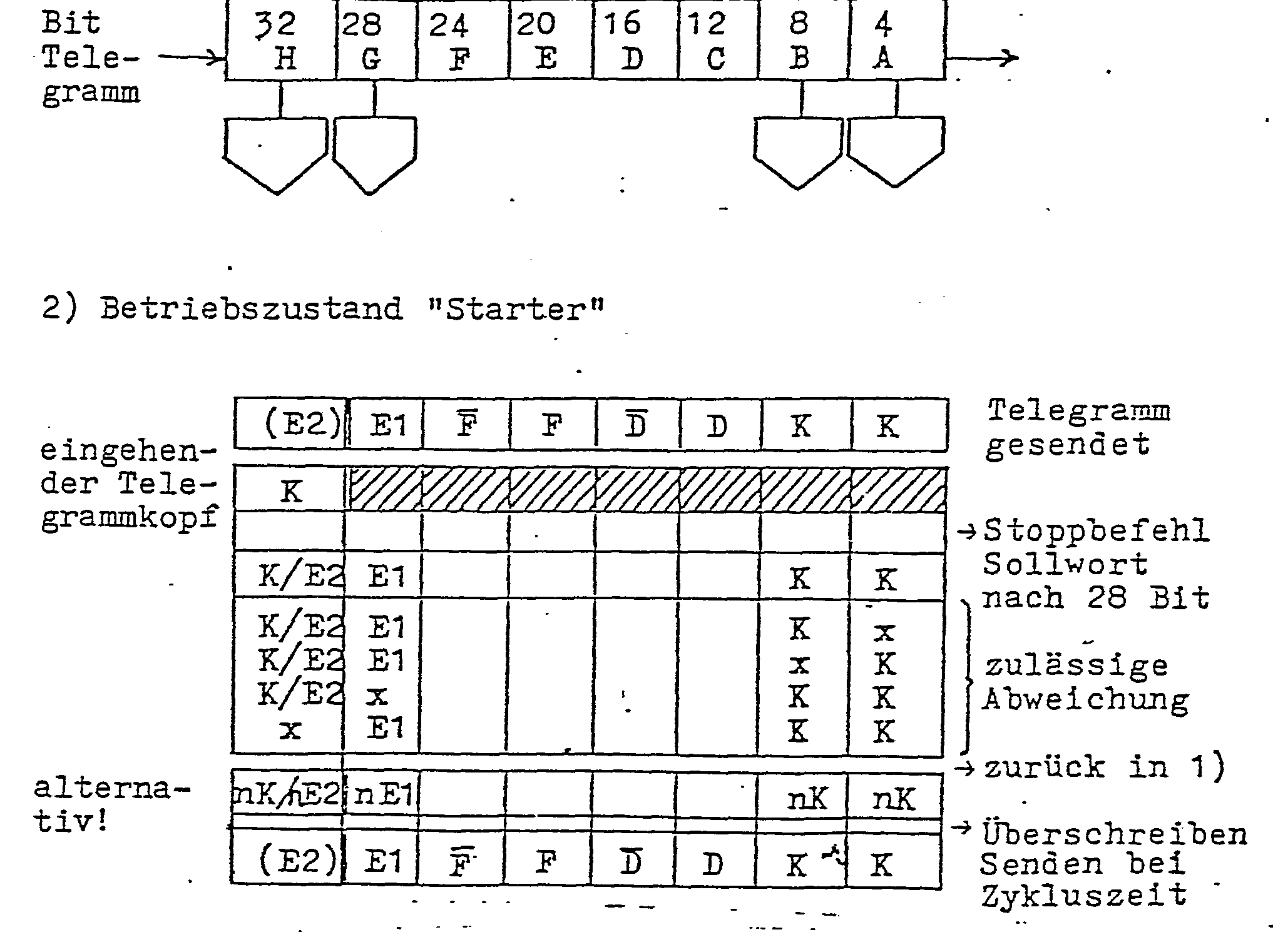
Das Ausbleiben von Telemetriesignalen wird in der nächsten Telemetrieeinheit als Betriebsstörung interpretiert. Infolge fehlender Rücksetzsignale veranlaßt der Wartezeitzähler WZ nach Ablauf der Wartezeit die zentrale Steuerung ST in den sogenannten "Starterbetrieb" überzugehen. Dies ist als zweiter Betriebszustand in der Tabelle dargestellt. Die Telemetrieeinheit beginnt dann mit der Aussendung ihres eigenen Telegramms mit nachfolgendem Schlußzeichen E2 im Takte der Zykluszeit der Telegrammkette Tk, Während eines derartigen Zyklus kann aber die Störung im vorausgehenden Übertragungsabschnitt behoben sein, so daß die als Starter wirksame Telemetrieeinheit plötzlich wieder Telemetriesignale von der vorausgehenden Telemetrieeinheit erhält. Im Hinblick darauf ist die gesamte Schieberegisteranordnung in ein erstes Schieberegister SR1 mit vier Stufen und ein zweites Schieberegister SR2 mit 28 Stufen durch einen dazwischengeschalteten digitalen Schalter S unterteilt. Im Starterbetrieb sind die beiden Schieberegister durch den in diesem Falle offenen digitalen Schalter S aufgetrennt. Das zweite Schieberegister SR2 dient dann zum Aussenden des eigenen Telegramms mit nachfolgendem Schlußzeichen 32, während das erste Schieberegister SR1, durch den asynchronen Takt des Decoders DEC taktiert, weiterhin für das Einlesen möglicher neuer Telegramme zur Verfügung steht. Erkennt nun der Rahmenerkenner und Datenprüfer RD das erste oder zweite Kopfkennwort K1, K2, so wird die zentrale Steuerung ST umgeschaltet und damit der Starterbetrieb unterbrochen. Dabei wird der digitale Schalter S zum zweiten Schieberegister SR2 geschlossen und das eingehende Telegramm mit dem Takt des Decoders in das zweite Schieberegister eingelesen, außerdem wird über den Dacodertakt der als Phasenregelschleife aufgebaute Taktoszillator TO nachsynchronisiert. Wird von dem Rahmen - erkenner und Datenprüfer RD der Rahmen des Telegramms nach den bereits erläuterten Kriterien erkannt, dann wird die zentrale Steuerung ST veranlaßt, vom Starterauf den Normalbetrieb zurückzuschalten. Der Normalbetrieb läuft dann in der bereits geschilderten Weise ab.The absence of telemetry signals is interpreted as a malfunction in the next telemetry unit. As a result of missing reset signals, the waiting time counter WZ causes the central control ST to change over to the so-called "starter mode" after the waiting time has expired. This is shown as the second operating state in the table. The telemetry unit starts then with the transmission of its own telegram with the following final character E2 in time with the cycle time of the telegram chain Tk, but during such a cycle the fault in the previous transmission section can be remedied, so that the telemetry unit effective as a starter suddenly receives telemetry signals from the previous telemetry unit again. In this regard, the entire shift register arrangement is subdivided into a first shift register SR1 with four stages and a second shift register SR2 with 28 stages by an interposed digital switch S. In the starter mode, the two shift registers are separated by the digital switch S which is open in this case. The second shift register SR2 is then used to send out its own telegram followed by the final character 32, while the first shift register SR1, clocked by the asynchronous clock of the decoder DEC, is still available for reading in possible new telegrams. If the frame recognizer and data tester RD now recognizes the first or second header password K1, K2, the central control ST is switched over and the starter operation is thus interrupted. The digital switch S is closed to the second shift register SR2 and the incoming telegram is read into the second shift register with the clock of the decoder. In addition, the clock oscillator TO, which is constructed as a phase locked loop, is re-synchronized via the decoder clock. If the frame recognizer and data checker RD recognizes the frame of the telegram according to the criteria already explained, then the central control ST is caused to switch back from the starter to normal operation. Normal operation then runs in the manner already described.
Erkennt der Rahmenerkenner und Datenprüfer RD während des Synchronisierzustandes binnen 28 Bit den Rahmen jedoch nicht, verbleibt die Telemetrieeinheit im Starterbetrieb. Der digitale Schalter S zwischen den beiden Schieberegistern wird wieder geöffnet, der TaktoszillatorTO auf seine mittlere Schwingfrequenz zurückgeführt. und die Aussendung des eigenen Telegramms mit nachfolgenden Schlußzeichen mit Hilfe des separierten zweiten Schieberegisters im Takte der Zykluszeit fortgesetzt.The frame recognizer and data checker RD recognizes the frame within 28 bits during the synchronization state however, the telemetry unit does not remain in starter mode. The digital switch S between the two shift registers is opened again and the clock oscillator TO is returned to its mean oscillation frequency. and the transmission of the own telegram with subsequent final characters is continued with the aid of the separated second shift register in the cycle time cycle.
Der Betriebszustand "Starter" der Telemetrieeinheit ist aufgrund der beschriebenen Abläufe die zwangsweise Folge der Nichterkennung von Telegrammrahmen nach Ablauf der Wartezeit. Im Ausführungsbeispiel wurde deshalb die Wartezeit doppelt so groß wie die Zykluszeit gewählt-; Die Telemetrieeinheit kehrt damit nur dann in den Normalbetrieb zurück, und das vom einen Bit zum nächsten, wenn sie den Rahmen eines eingehenden Telegramms nach den erwähnten Kriterien richtig erkannt hat. Dadurch ist sichergestellt, daß ein Normalbetrieb aufgrund vorgetäuschter Telemetriedaten weitgehend unterbunden ist.The operating state "starter" of the telemetry unit is, due to the described processes, the inevitable consequence of the non-detection of telegram frames after the waiting time has expired. In the exemplary embodiment, the waiting time was therefore chosen to be twice the cycle time; The telemetry unit thus only returns to normal operation, and from one bit to the next, if it has correctly recognized the frame of an incoming telegram according to the criteria mentioned. This ensures that normal operation due to simulated telemetry data is largely prevented.
Das Ausführungsbeispiel konnte mittels integrierter C-MOS-Bausteine realisiert werden, wobei die Übertragungsrate der digitalen Telemetriesignale bei 2,4 kbit/s und die höchstzulässige Rate von Meldedaten am ersten Eingang E1 bei etwa 3 Mbit/s lag.The exemplary embodiment could be implemented by means of integrated C-MOS modules, the transmission rate of the digital telemetry signals being 2.4 kbit / s and the maximum permissible rate of registration data at the first input E1 being approximately 3 Mbit / s.
Claims (6)
Priority Applications (1)
| Application Number | Priority Date | Filing Date | Title |
|---|---|---|---|
| AT83108586T ATE34891T1 (en) | 1982-09-02 | 1983-08-31 | OPERATION MONITORING OF DIGITAL TRANSMISSION LINES. |
Applications Claiming Priority (2)
| Application Number | Priority Date | Filing Date | Title |
|---|---|---|---|
| DE19823232681 DE3232681A1 (en) | 1982-09-02 | 1982-09-02 | OPERATIONAL MONITORING OF DIGITAL TRANSMISSION ROUTES |
| DE3232681 | 1982-09-02 |
Publications (3)
| Publication Number | Publication Date |
|---|---|
| EP0106985A2 true EP0106985A2 (en) | 1984-05-02 |
| EP0106985A3 EP0106985A3 (en) | 1986-07-16 |
| EP0106985B1 EP0106985B1 (en) | 1988-06-01 |
Family
ID=6172326
Family Applications (1)
| Application Number | Title | Priority Date | Filing Date |
|---|---|---|---|
| EP83108586A Expired EP0106985B1 (en) | 1982-09-02 | 1983-08-31 | Operation monitoring of digital transmission links |
Country Status (4)
| Country | Link |
|---|---|
| EP (1) | EP0106985B1 (en) |
| JP (1) | JPS5964949A (en) |
| AT (1) | ATE34891T1 (en) |
| DE (2) | DE3232681A1 (en) |
Cited By (5)
| Publication number | Priority date | Publication date | Assignee | Title |
|---|---|---|---|---|
| EP0199326A2 (en) * | 1985-04-22 | 1986-10-29 | Siemens Aktiengesellschaft | Operation monitoring of digital transmission links |
| DE3726573A1 (en) * | 1987-08-10 | 1989-02-23 | Siemens Ag | In-operation monitoring of communication transmission lines |
| GB2328125A (en) * | 1997-08-08 | 1999-02-10 | Ericsson Telefon Ab L M | Network control system |
| DE4308730C2 (en) * | 1993-03-19 | 2003-04-24 | Philips Corp Intellectual Pty | Device for determining at least one code error measure |
| DE102009037721A1 (en) * | 2009-08-17 | 2011-04-28 | Siemens Aktiengesellschaft | Devices and methods for identifying external influences on at least one processing unit of an embedded system |
Citations (3)
| Publication number | Priority date | Publication date | Assignee | Title |
|---|---|---|---|---|
| GB1401261A (en) * | 1972-01-13 | 1975-07-16 | Siemens Ag | Data transmission systems |
| EP0044556A1 (en) * | 1980-07-22 | 1982-01-27 | Siemens Aktiengesellschaft | Method of monitoring repeating regenerators |
| GB2094110A (en) * | 1981-01-30 | 1982-09-08 | Eltra Corp | A method and apparatus for locating a discontinuity in a data transmission |
-
1982
- 1982-09-02 DE DE19823232681 patent/DE3232681A1/en not_active Withdrawn
-
1983
- 1983-08-31 DE DE8383108586T patent/DE3376944D1/en not_active Expired
- 1983-08-31 EP EP83108586A patent/EP0106985B1/en not_active Expired
- 1983-08-31 AT AT83108586T patent/ATE34891T1/en active
- 1983-09-02 JP JP58160577A patent/JPS5964949A/en active Pending
Patent Citations (3)
| Publication number | Priority date | Publication date | Assignee | Title |
|---|---|---|---|---|
| GB1401261A (en) * | 1972-01-13 | 1975-07-16 | Siemens Ag | Data transmission systems |
| EP0044556A1 (en) * | 1980-07-22 | 1982-01-27 | Siemens Aktiengesellschaft | Method of monitoring repeating regenerators |
| GB2094110A (en) * | 1981-01-30 | 1982-09-08 | Eltra Corp | A method and apparatus for locating a discontinuity in a data transmission |
Cited By (8)
| Publication number | Priority date | Publication date | Assignee | Title |
|---|---|---|---|---|
| EP0199326A2 (en) * | 1985-04-22 | 1986-10-29 | Siemens Aktiengesellschaft | Operation monitoring of digital transmission links |
| EP0199326A3 (en) * | 1985-04-22 | 1988-12-14 | Siemens Aktiengesellschaft Berlin Und Munchen | Operation monitoring of digital transmission links |
| DE3726573A1 (en) * | 1987-08-10 | 1989-02-23 | Siemens Ag | In-operation monitoring of communication transmission lines |
| DE4308730C2 (en) * | 1993-03-19 | 2003-04-24 | Philips Corp Intellectual Pty | Device for determining at least one code error measure |
| GB2328125A (en) * | 1997-08-08 | 1999-02-10 | Ericsson Telefon Ab L M | Network control system |
| GB2328125B (en) * | 1997-08-08 | 2002-04-10 | Ericsson Telefon Ab L M | Network control system |
| US6560653B1 (en) | 1997-08-08 | 2003-05-06 | Telefonaktiebolaget Lm Ericsson (Publ) | System and method for processing a signalling message in an ATM network |
| DE102009037721A1 (en) * | 2009-08-17 | 2011-04-28 | Siemens Aktiengesellschaft | Devices and methods for identifying external influences on at least one processing unit of an embedded system |
Also Published As
| Publication number | Publication date |
|---|---|
| ATE34891T1 (en) | 1988-06-15 |
| EP0106985A3 (en) | 1986-07-16 |
| JPS5964949A (en) | 1984-04-13 |
| DE3376944D1 (en) | 1988-07-07 |
| EP0106985B1 (en) | 1988-06-01 |
| DE3232681A1 (en) | 1984-03-08 |
Similar Documents
| Publication | Publication Date | Title |
|---|---|---|
| DE3136128C2 (en) | ||
| EP0213063A1 (en) | Circuit arrangement for testing a passive bus network (CSMA/CD access method) | |
| DE3027755A1 (en) | METHOD FOR MONITORING INTERIM REGENERATORS | |
| DE2527593A1 (en) | METHOD AND DEVICE FOR REMOTE MONITORING AND FAULT LOCATION OF PULSE GENERATORS | |
| DE3418084A1 (en) | REMOTE MONITORING DEVICE FOR DATA TRANSFER | |
| DE3004767B1 (en) | Method for combined monitoring and fault location in transmission links for digital signals and arrangement for carrying out the method | |
| EP0374303B1 (en) | Process for the individual monitoring of transmission sections of a communications transmission link, and apparatus for carrying out the process | |
| EP0106985B1 (en) | Operation monitoring of digital transmission links | |
| DE3125724C2 (en) | ||
| EP0009600B1 (en) | Method and interface device for carrying out maintenance operations over an interface between a maintenance processor and a plurality of individually testable functional units of a data processing system | |
| DE4218499C2 (en) | Fault detection device for a transmission system | |
| EP0044556B1 (en) | Method of monitoring repeating regenerators | |
| EP0013944B1 (en) | Method and arrangement for error location in, and the monitoring of, a communication link | |
| DE3506945A1 (en) | METHOD FOR COLLECTING MONITORING INFORMATION IN TRANSMISSION DEVICES AND ARRANGEMENT FOR IMPLEMENTING THE METHOD | |
| DE3726573C2 (en) | ||
| DE3044401C2 (en) | Procedure for monitoring and locating faults in PCM transmission systems | |
| EP0204248B1 (en) | Digital transmission link with series-connected telemetry channels | |
| DE3522446C1 (en) | Fault location circuit arrangement for a line transmission device | |
| DE3207397A1 (en) | Method for monitoring the functional capacity of a digital transmission path | |
| EP0567204B1 (en) | Method and circuit for monitoring digital periodical signals | |
| AT367582B (en) | DEVICE FOR DETECTING DEFECTIVE PACKAGES | |
| DE3109059A1 (en) | Method and arrangement for error location in a digital transmission path | |
| DE19511178A1 (en) | Data transfer system for industrial control systems with diagnostic function for locating faults | |
| EP0392246B1 (en) | Monitoring and control system for digital information transmission systems with master and substitution master | |
| DE3340151C2 (en) | Alarm signal collective transmission device |
Legal Events
| Date | Code | Title | Description |
|---|---|---|---|
| PUAI | Public reference made under article 153(3) epc to a published international application that has entered the european phase |
Free format text: ORIGINAL CODE: 0009012 |
|
| AK | Designated contracting states |
Designated state(s): AT BE CH DE FR GB IT LI NL SE |
|
| 17P | Request for examination filed |
Effective date: 19841219 |
|
| PUAL | Search report despatched |
Free format text: ORIGINAL CODE: 0009013 |
|
| AK | Designated contracting states |
Kind code of ref document: A3 Designated state(s): AT BE CH DE FR GB IT LI NL SE |
|
| 17Q | First examination report despatched |
Effective date: 19870914 |
|
| GRAA | (expected) grant |
Free format text: ORIGINAL CODE: 0009210 |
|
| AK | Designated contracting states |
Kind code of ref document: B1 Designated state(s): AT BE CH DE FR GB IT LI NL SE |
|
| PG25 | Lapsed in a contracting state [announced via postgrant information from national office to epo] |
Ref country code: IT Free format text: LAPSE BECAUSE OF FAILURE TO SUBMIT A TRANSLATION OF THE DESCRIPTION OR TO PAY THE FEE WITHIN THE PRESCRIBED TIME-LIMIT;WARNING: LAPSES OF ITALIAN PATENTS WITH EFFECTIVE DATE BEFORE 2007 MAY HAVE OCCURRED AT ANY TIME BEFORE 2007. THE CORRECT EFFECTIVE DATE MAY BE DIFFERENT FROM THE ONE RECORDED. Effective date: 19880601 |
|
| REF | Corresponds to: |
Ref document number: 34891 Country of ref document: AT Date of ref document: 19880615 Kind code of ref document: T |
|
| PG25 | Lapsed in a contracting state [announced via postgrant information from national office to epo] |
Ref country code: SE Effective date: 19880630 |
|
| REF | Corresponds to: |
Ref document number: 3376944 Country of ref document: DE Date of ref document: 19880707 |
|
| ET | Fr: translation filed | ||
| PG25 | Lapsed in a contracting state [announced via postgrant information from national office to epo] |
Ref country code: GB Free format text: LAPSE BECAUSE OF NON-PAYMENT OF DUE FEES Effective date: 19881122 |
|
| GBV | Gb: ep patent (uk) treated as always having been void in accordance with gb section 77(7)/1977 [no translation filed] | ||
| PLBE | No opposition filed within time limit |
Free format text: ORIGINAL CODE: 0009261 |
|
| STAA | Information on the status of an ep patent application or granted ep patent |
Free format text: STATUS: NO OPPOSITION FILED WITHIN TIME LIMIT |
|
| 26N | No opposition filed | ||
| PGFP | Annual fee paid to national office [announced via postgrant information from national office to epo] |
Ref country code: BE Payment date: 19890824 Year of fee payment: 7 |
|
| PG25 | Lapsed in a contracting state [announced via postgrant information from national office to epo] |
Ref country code: NL Effective date: 19900301 |
|
| NLV4 | Nl: lapsed or anulled due to non-payment of the annual fee | ||
| PG25 | Lapsed in a contracting state [announced via postgrant information from national office to epo] |
Ref country code: FR Effective date: 19900427 |
|
| REG | Reference to a national code |
Ref country code: FR Ref legal event code: ST |
|
| PG25 | Lapsed in a contracting state [announced via postgrant information from national office to epo] |
Ref country code: BE Effective date: 19900831 |
|
| BERE | Be: lapsed |
Owner name: SIEMENS A.G. BERLIN UND MUNCHEN Effective date: 19900831 |
|
| PGFP | Annual fee paid to national office [announced via postgrant information from national office to epo] |
Ref country code: AT Payment date: 19930716 Year of fee payment: 11 |
|
| PGFP | Annual fee paid to national office [announced via postgrant information from national office to epo] |
Ref country code: DE Payment date: 19931020 Year of fee payment: 11 |
|
| PGFP | Annual fee paid to national office [announced via postgrant information from national office to epo] |
Ref country code: CH Payment date: 19931116 Year of fee payment: 11 |
|
| PG25 | Lapsed in a contracting state [announced via postgrant information from national office to epo] |
Ref country code: LI Effective date: 19940831 Ref country code: CH Effective date: 19940831 Ref country code: AT Effective date: 19940831 |
|
| REG | Reference to a national code |
Ref country code: CH Ref legal event code: PL |
|
| PG25 | Lapsed in a contracting state [announced via postgrant information from national office to epo] |
Ref country code: DE Effective date: 19950503 |