EP0106777A1 - Sea swell characteristics measuring apparatus - Google Patents
Sea swell characteristics measuring apparatus Download PDFInfo
- Publication number
- EP0106777A1 EP0106777A1 EP83460002A EP83460002A EP0106777A1 EP 0106777 A1 EP0106777 A1 EP 0106777A1 EP 83460002 A EP83460002 A EP 83460002A EP 83460002 A EP83460002 A EP 83460002A EP 0106777 A1 EP0106777 A1 EP 0106777A1
- Authority
- EP
- European Patent Office
- Prior art keywords
- buoy
- swell
- axis
- projection
- acceleration
- Prior art date
- Legal status (The legal status is an assumption and is not a legal conclusion. Google has not performed a legal analysis and makes no representation as to the accuracy of the status listed.)
- Granted
Links
Images


Classifications
-
- G—PHYSICS
- G01—MEASURING; TESTING
- G01P—MEASURING LINEAR OR ANGULAR SPEED, ACCELERATION, DECELERATION, OR SHOCK; INDICATING PRESENCE, ABSENCE, OR DIRECTION, OF MOVEMENT
- G01P15/00—Measuring acceleration; Measuring deceleration; Measuring shock, i.e. sudden change of acceleration
-
- G—PHYSICS
- G01—MEASURING; TESTING
- G01P—MEASURING LINEAR OR ANGULAR SPEED, ACCELERATION, DECELERATION, OR SHOCK; INDICATING PRESENCE, ABSENCE, OR DIRECTION, OF MOVEMENT
- G01P13/00—Indicating or recording presence, absence, or direction, of movement
- G01P13/02—Indicating direction only, e.g. by weather vane
Definitions
- the present invention relates to an apparatus for measuring the vertical acceleration due to swell, the slope of the free surface of water, and the direction of swell.
- the measuring assembly is outside the middle and, in the other, it is included in the middle.
- SEASAT SEASAT
- a radar pulse from a geostationary satellite and analyze this pulse on the return to extract the amplitude and direction of the swell.
- Another project uses an HF radar, with the emission of a RADAR pulse which, after ionospheric reflection, is reflected by the surface of the water. Measurement and the analysis of the Doppler effect on this pulse must make it possible to determine the amplitude and the direction of the swell.
- a direct radar is used, with the emission of a RADAR pulse towards the surface of the water. After reflection, this pulse is analyzed and must be able to determine the amplitude and direction of the swell.
- the measuring system When the measuring system is included in the medium, it is housed in a buoy, which, directly subjected to the swell, has three degrees of freedom. In this case, you must first decide on the frame of reference in which the measurement is performed. We can consider either the enslavement of the reference frame vertically, or the enslavement of the reference frame on the surface.
- the vertical control can be performed by a gyroscopic crew fixed on the vertical of the place. This solution, which has been the most explored and exploited, as attractive as it may seem, is no less cumbersome and consuming. Vertical control can also find a solution in the use of gravity.
- a spherical swell buoy is known which operates with an accelerometer mounted on a circular plate which plate moves in a sphere. The external reference there is the acceleration of gravity% which in all points of the terrestrial globe is directed along the vertical.
- the vertical control is completely dissociated from the measurement of the swell acceleration. It is therefore necessary that the natural oscillation frequency of the moving equipment is much lower than the frequency band in which the swell spectrum is located (0.1 s to 60 s).
- the mechanical separation between the measurement and the servo implies a large sensor size, the filling of the sphere with a liquid, such as for example glycerine, and very good mechanical characteristics of the wire supporting the moving assembly. .
- This type of control only allows knowledge of the vertical acceleration vector of the swell.
- the object of the present invention is to propose a measuring device operating with servo-control of the reference frame on the sea surface, this device making it possible to apprehend the parameters that are the vertical acceleration due to the swell, the slope of the free surface of water, and the direction of the swell, while bringing advantages compared to the existing materials.
- gyroscopic servo buoys are generally bulky, therefore difficult to use especially since they require significant energy reserves.
- the gravity system which has been the most widely used in recent years, has the disadvantage of only showing the vertical acceleration due to the swell.
- the present invention which aims to provide a buoy of small dimensions and low consumption to acquire the parameters: vertical acceleration of the swell, slope of the swell, and direction of the swell, is of interest, both in the scientific field, with regard to the study of the marine environment and the swell phenomenon, than in the technical field, with regard to the knowledge of the stresses to which marine works are subjected.
- an apparatus for measuring wave characteristics at sea comprising a buoy whose main plane follows the free surface of the water, an accelerometer mounted along the axis of the buoy, two orthogonal acoelerometers mounted in the main plane of the buoy, and a triaxial magnetoneter.
- the axes of the triaxial magnetoateter are merged with those of the accelerometers.
- the buoy supports, in addition to the sensors, the energy source and the electronic equipment necessary for the processing, recording and / or transmission of information relating to swells.
- the acceleration due to swell being normal to the free surface of the water
- the accelerometer mounted along the axis of the buoy measures the sum of the acceleration due to swell and the projection of the acceleration of gravity g along the axis of the buoy.
- the two orthogonal accelerometers mounted in the main plane of the buoy measure the components of the projection of the vector g in the main plane of the buoy. Knowing the value of g and the values of the components of g in the main plane of the buoy, we deduce the projection of the vectorg along the axis of the buoy, then we deduce this value from the value measured by the first accelerometer. The result of the subtraction is the value of the acceleration due to the swell.
- the value of the projection of the vector g along the axis of the buoy makes it possible to know the inclination of this axis relative to the vertical, which gives directly the slope of the free surface of the water. Knowing the value of the acceleration due to the swell and its inclination relative to the vertical, we deduce the vertical acceleration due to the swell.
- the magnetometer makes it possible to determine the earth's magnetic field vector with respect to the buoy.
- the direction of the swell is defined as the angle of the horizontal projection of the acceleration vector due to the swell with the horizontal projection of the magnetic field vector.
- the horizontal plane is defined in relation to the buoy by knowledge of the vector]. It is therefore possible to determine the direction of the swell.
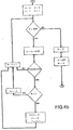
- Figs. 4a to 4g are flowcharts illustrating the operation of the computer of the measuring device.
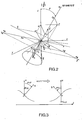
- the measuring device shown in Fig. 1, comprises a buoy 1 which essentially consists of a disc 2 carrying a mast 3 oriented along its axis of revolution.
- a buoy 1 which essentially consists of a disc 2 carrying a mast 3 oriented along its axis of revolution.
- three orthogonal accelerometers Gl, G2 and G3 are mounted, three magnetometers Bl, B2 and B3.
- the accelerometer G3 and the magnetometer B3 are oriented along the axis Oz of the mast 3.
- the accelerometer Gl and the magnetometer Bl are oriented in the same direction Ox while the accelerometer G2 and the magnetometer B2 are oriented in the same direction Oy, Ox and Oy being perpendicular to each other in the plane of the disc 2.
- the measuring device is completed by an electronic box 4 which contains the power source or sources necessary to power the accelerometers and magnetometers.
- the values of the recorded signals are processed in a digital computer which can be in box 4, or remotely. Finally, the device is completed by a data transmitter 5 connected to an antenna 6 mounted at the end of the mast 2. When the processing computer is in the box 4, the data transmitted by 5 comes from the computer. When the computer is remote, the data to be transmitted is supplied by the individual recording circuits.
- the accelerometers Gl, G2, and G3 are integral with the buoy, the measurement values which they deliver are referred to the reference trihedron Ox, Oy, Oz, FIG. 2, which is essentially mobile.
- the magnetic field vector B is used as auxiliary reference which is supposed to be completely defined at the place of mooring of the buoy and which is measured by the magnetometers B 1, B2, B3 integral with the reference trihedron Ox, Oy, Oz.
- V Z makes it possible to lift the indeterminacies of sign on p and of on d, these indeterminacies being inevitable since the configuration of the accelerometers and magnetometers does not favor a horizontal direction.
- A being the constant angle of the vertical of the place and the earth's magnetic field and B the constant modulus of the magretic field, A and B depending only on the place of wetting.
- Equation (5) in ⁇ is therefore a second degree equation which has two solutions: ⁇ 1 and ⁇ 2 , defining two vectors Z 1 (a1, b1, c1) and Z 2 (a2, b2, c2).
- This double solution is geometrically understood, because Z is provided by the intersection of a plane, containing G and Zz , and a cone with axis B and opening A.
- Equation (6) makes it possible to know the sign of V Z1 and, on the other hand, cl is equal to - (L + ⁇ K), therefore:
- L (B.cos A) .Bz -1 is always negative if the slope p of the swell remains less than (90 ° - A), which corresponds to the case of a little rough sea.
- the vertical speed must be substantially zero when the buoy is itself vertical, that is to say a crest or a trough.
- the parameter L can vary according to two different paces:
- phase 0 ( ⁇ ) from phase 2 from phase 2 ( ⁇ ) via V Zj .
- ⁇ a speed V Zj ⁇
- V Zj 0, if we are in phase 0.
- the slope of the swell can be estimated with the only indications of the accelerometers, since: is or
- Fig. 4a it has been indicated that the measurements carried out by the accelerometers and the magnetometers are sampled, at the rate of 2 Hz, so as to obtain for each of the measured values 2,048 consecutive samples which are memorized at each measurement phase.
- the measurement phase therefore corresponds to the recording of the wave parameters for approximately 20 minutes.
- the flow diagram of FIG. 4b indicates how from the difference between the projection of the acceleration G undergone by the buoy and gravity, the rows N of the stored samples are deduced therefrom for which the buoy is on a crest or at the bottom of a trough.
- R1 gives the number of peaks and troughs in the waves during the 20 minutes of recording and Q is equal to the average of the vertical projection of the magnetic field.
- Fig. 4g the output data have been defined, ie Tl and Ll which form the components of the slope, Vl which corresponds to the vertical acceleration V z and the direction Dl corresponding to d. Note that we use the intermediate variables I, J and V which are defined in Fig. 4a.
- buoy 1 is obviously wet, as indicated by the rope 7.
- the orientation of the buoy is stabilized by a floating anchor 8.
Abstract
L'appareil comprend une bouée (1) dont le plan principal (2) suit la surface libre de l'eau. Sont montés sur la bouée (1), un accéléromètre (G3) dirigé selon l'axe (Ox) de la bouée (1), deux accéléromètres orthogonaux (G1, G2) montés dans le plan principal (Ox, Oy) de la bouée (1), et un magnétomètre triaxial (B1, B2, B3). Les axes du magnétomètre sont confondus avec ceux des accéléromètres. Les mesures effectuées servent à calculer notamment la projection du vecteur vertical unité (OZ) sur l'axe (Oz) de la bouée (1) pour avoir la pente (p) et les angles des projections, sur le plan horizontal du lieu, de l'axe (Oz) de la bouée (1) et du champ magnétique (B) pour avoir la direction (d) de la houle. La vitesse verticale (Vz) de la bouée (1) est aussi évaluée pour lever des indéterminations.The apparatus comprises a buoy (1) whose main plane (2) follows the free surface of the water. Are mounted on the buoy (1), an accelerometer (G3) directed along the axis (Ox) of the buoy (1), two orthogonal accelerometers (G1, G2) mounted in the main plane (Ox, Oy) of the buoy (1), and a triaxial magnetometer (B1, B2, B3). The axes of the magnetometer are merged with those of the accelerometers. The measurements carried out are used to calculate in particular the projection of the vertical vector unit (OZ) on the axis (Oz) of the buoy (1) to have the slope (p) and the angles of the projections, on the horizontal plane of the place, of the axis (Oz) of the buoy (1) and the magnetic field (B) to have the direction (d) of the swell. The vertical speed (Vz) of the buoy (1) is also evaluated to remove indeterminacies.
Description
La présente invention concerne un appareil de mesure de l'accélération verticale due à la houle, la pente de la surface libre de l'eau, et la direction de la houle.The present invention relates to an apparatus for measuring the vertical acceleration due to swell, the slope of the free surface of water, and the direction of swell.
La mesure de ces trois paramètres n'a d'existence que par rapport à un repère fixe dans l'espace qui peut être défini de la façon suivante:
- - l'axe Oz est dirigé suivant la verticale ascendante du lieu, c'est à dire la direction du fil à plomb,
- - l'axe Oy est dirigé vers le Nord magnétique, et
- - l'axe Ox est dirigé vers l'Est magnétique.
- - the axis Oz is directed along the upward vertical of the place, that is to say the direction of the plumb line,
- - the axis Oy is directed towards magnetic North, and
- - the axis Ox is directed towards the magnetic East.
On connaît des appareils de mesure des paramètres de la houle fonctionnant suivant deux principes différents. Dans un cas, l'ensemble de mesure est extérieur au milieu et, dans l'autre, il est inclus dans le milieu.There are known wave measurement parameters operating according to two different principles. In one case, the measuring assembly is outside the middle and, in the other, it is included in the middle.
En ce qui concerne les appareils fonctionnant en dehors du milieu, trois études sont actuellement en cours. Dans le projet dit SEASAT, il est prévu l'émission à partir d'un satellite géostationnaire d'une impulsion radar et l'analyse de cette impulsion au retour pour en extraire l'amplitude et la direction de la houle. Un autre projet utilise un radar HF, avec émission d'une impulsion RADAR qui, après réflexion ionosphérique, est réfléchie par la surface de l'eau. La mesure et l'analyse de l'effet Doppler sur cette impulsion doit permettre de déterminer l'amplitude et la direction de la houle. Dans un troisième projet, on utilise un radar direct, avec émission d'une impulsion RADAR vers la surface de l'eau. Après réflexion, cette impulsion est analysée et doit pouvoir permettre de déterminer l'amplitude et la direction de la houle.With regard to devices operating outside the environment, three studies are currently underway. In the so-called SEASAT project, it is planned to send a radar pulse from a geostationary satellite and analyze this pulse on the return to extract the amplitude and direction of the swell. Another project uses an HF radar, with the emission of a RADAR pulse which, after ionospheric reflection, is reflected by the surface of the water. Measurement and the analysis of the Doppler effect on this pulse must make it possible to determine the amplitude and the direction of the swell. In a third project, a direct radar is used, with the emission of a RADAR pulse towards the surface of the water. After reflection, this pulse is analyzed and must be able to determine the amplitude and direction of the swell.
Quand l'ensemble de mesure est inclus dans le milieu, il est logé dans une bouée, laquelle, directement soumise à la houle, possède trois degrés de liberté. Dans ce cas, il faut d'abord décider du référentiel dans lequel est effectuée la mesure. On peut envisager, soit l'asservissement du référentiel à la verticale, soit l'asservissement du référentiel à la surface.When the measuring system is included in the medium, it is housed in a buoy, which, directly subjected to the swell, has three degrees of freedom. In this case, you must first decide on the frame of reference in which the measurement is performed. We can consider either the enslavement of the reference frame vertically, or the enslavement of the reference frame on the surface.
L'asservissement à la verticale peut être réalisé par un équipage gyroscopique calé sur la verticale du lieu. Cette solution, qui a été la plus explorée et exploitée, aussi séduisante qu'elle puisse paraître, n'en est pas moins lourde et consommante. L'asservissement à la verticale peut également trouver une solution dans l'utilisation de la pesanteur. On connaît une bouée de houle sphérique qui fonctionne avec un accéléromètre monté sur un plateau circulaire lequel plateau se déplace dans une sphère. La référence extérieure y est l'accélération de la pesanteur% qui en tous points du globe terrestre est dirigée suivant la verticale. L'asservissement suivant la verticale est complètement dissocié de la mesure de l'accélération de la houle. Il faut donc que la fréquence d'oscillation propre de l'équipage mobile soit très inférieure à la bande de fréquence dans laquelle se situe le spectre de houle (0,1s à 60s). En pratique, la séparation mécanique entre la mesure et l'asservissement implique une taille de capteur importante, le remplissage de la sphère par un liquide, tel que par exemple de la glycérine, et de très bonnes caractéristiques mécaniques du fil supportant l'équipage mobile. Ce type d'asservissement ne permet la connaissance que du vecteur accélération verticale de la houle.The vertical control can be performed by a gyroscopic crew fixed on the vertical of the place. This solution, which has been the most explored and exploited, as attractive as it may seem, is no less cumbersome and consuming. Vertical control can also find a solution in the use of gravity. A spherical swell buoy is known which operates with an accelerometer mounted on a circular plate which plate moves in a sphere. The external reference there is the acceleration of gravity% which in all points of the terrestrial globe is directed along the vertical. The vertical control is completely dissociated from the measurement of the swell acceleration. It is therefore necessary that the natural oscillation frequency of the moving equipment is much lower than the frequency band in which the swell spectrum is located (0.1 s to 60 s). In practice, the mechanical separation between the measurement and the servo implies a large sensor size, the filling of the sphere with a liquid, such as for example glycerine, and very good mechanical characteristics of the wire supporting the moving assembly. . This type of control only allows knowledge of the vertical acceleration vector of the swell.
La présente invention a pour objet de proposer un appareil de mesure fonctionnant avec asservissement du référentiel à la surface de la mer, cet appareil permettant d'appréhender les paramètres que sont l'accélération verticale due à la houle, la pente de la surface libre de l'eau, et la direction de la houle, tout en apportant des avantages par rapport aux matériels existants.The object of the present invention is to propose a measuring device operating with servo-control of the reference frame on the sea surface, this device making it possible to apprehend the parameters that are the vertical acceleration due to the swell, the slope of the free surface of water, and the direction of the swell, while bringing advantages compared to the existing materials.
Quantitativement, on peut dire que les ensembles réalisant des mesures hors du milieu font appel à des techniques et à des matériels sophistiqués nécessitant la mise en place de moyens en personnel et en budget importants.Quantitatively, it can be said that the units carrying out measurements outside the environment call on sophisticated techniques and materials requiring the implementation of significant personnel and budget resources.
Pour ce qui est des mesures dans le milieu, les bouées à asservissement gyroscopiques sont généralement volumineuses, donc d'un emploi malaisé d'autant plus qu'elles nécessitent d'importantes réserves d'énergie. Le système utilisant la pesanteur, qui a été le plus largement utilisé durant les dernières années, présente cependant l'inconvénient de ne mettre en évidence que l'accélération verticale due à la houle.In terms of measurements in the environment, gyroscopic servo buoys are generally bulky, therefore difficult to use especially since they require significant energy reserves. The gravity system, which has been the most widely used in recent years, has the disadvantage of only showing the vertical acceleration due to the swell.
La présente invention qui a pour objet de prévoir une bouée de petites dimensions et de faible consommation permettant d'acquérir les paramètres: accélération verticale de la houle, pente de la houle, et direction de la houle, présente de l'intérêt, tant dans le domaine scientifique, en ce qui concerne l'étude du milieu marin et du phénomène de houle, que dans le domaine technique, en ce qui conaerne la connaissance des sollicitations auxquelles sont soumis les ouvrages marins.The present invention which aims to provide a buoy of small dimensions and low consumption to acquire the parameters: vertical acceleration of the swell, slope of the swell, and direction of the swell, is of interest, both in the scientific field, with regard to the study of the marine environment and the swell phenomenon, than in the technical field, with regard to the knowledge of the stresses to which marine works are subjected.
Suivant une caractéristique de l'invention, il est prévu un appareil de mesures de caractéristiques de la houle en mer comprenant une bouée dont le plan principal suit la surface libre de l'eau, un accéléromètre monté selon l'axe de la bouée, deux acoéléromètres orthogonaux montés dans le plan principal de la bouée, et un magnétonètre triaxial.According to a characteristic of the invention, there is provided an apparatus for measuring wave characteristics at sea comprising a buoy whose main plane follows the free surface of the water, an accelerometer mounted along the axis of the buoy, two orthogonal acoelerometers mounted in the main plane of the buoy, and a triaxial magnetoneter.
Suivant une autre caractéristique les axes du magnétoatètre triaxial sont confondus avec ceux des accéléromètres.According to another characteristic, the axes of the triaxial magnetoateter are merged with those of the accelerometers.
La bouée supporte, outre les capteurs, la source d'énergie et le matériel électronique nécessaires au traitement, à l'enregistrement et/ou la transmission des informations relatives à la houle.The buoy supports, in addition to the sensors, the energy source and the electronic equipment necessary for the processing, recording and / or transmission of information relating to swells.
L'accélération due à la houle étant normale à la surface libre de l'eau, l'accéléromètre monté selon l'axe de la bouée mesure la somme de l'accélération due à la houle et la projection de l'accélération de la pesanteur g selon l'axe de la bouée.The acceleration due to swell being normal to the free surface of the water, the accelerometer mounted along the axis of the buoy measures the sum of the acceleration due to swell and the projection of the acceleration of gravity g along the axis of the buoy.
Les deux accéléromètres orthogonaux montés dans le plan principal de la bouée mesurent les composantes de la projection du vecteur g dans le plan principal de la bouée. Connaissant la valeur de g et les valeurs des composantes de g dans le plan principal de la bouée, on en déduit la projection du vecteurg selon l'axe de la bouée, puis on déduit cette valeur de la valeur mesurée par le premier accéléromètre. Le résultat de la soustraction est la valeur de l'accélération due à la houle.The two orthogonal accelerometers mounted in the main plane of the buoy measure the components of the projection of the vector g in the main plane of the buoy. Knowing the value of g and the values of the components of g in the main plane of the buoy, we deduce the projection of the vectorg along the axis of the buoy, then we deduce this value from the value measured by the first accelerometer. The result of the subtraction is the value of the acceleration due to the swell.
La valeur de la projection du vecteur g selon l'axe de la bouée permet de connaître l'inclinaison de cet axe par rapport à la verticale, ce qui donne directement la pente de la surface libre de l'eau. Connaissant la valeur de l'accélération due à la houle et son inclinaison par rapport à la verticale, on en déduit l'accélération verticale due à la houle.The value of the projection of the vector g along the axis of the buoy makes it possible to know the inclination of this axis relative to the vertical, which gives directly the slope of the free surface of the water. Knowing the value of the acceleration due to the swell and its inclination relative to the vertical, we deduce the vertical acceleration due to the swell.
Le magnétomètre permet de déterminer le vecteur champ magnétique terrestre par rapport à la bouée. La direction de la houle est définie comme l'angle de la projection horizontale du vecteur accélération due à la houle avec la projection horizontale du vecteur champ magnétique. Le plan horizontal est défini par rapport à la bouée par la connaissance du vecteur]. Il est donc possible de déterminer la direction de la houle.The magnetometer makes it possible to determine the earth's magnetic field vector with respect to the buoy. The direction of the swell is defined as the angle of the horizontal projection of the acceleration vector due to the swell with the horizontal projection of the magnetic field vector. The horizontal plane is defined in relation to the buoy by knowledge of the vector]. It is therefore possible to determine the direction of the swell.
Les caractéristiques de l'invention mentionnées ci-dessus, ainsi que d'autres, apparaîtront plus clairement à la lecture de la description suivante d'un exemple de réalisation, ladite description étant faite en relation avec les dessins joints, parmi lesquels:
- la Fig. 1 est une vue schématique en perspective d'un appareil suivant l'invention, comprenant une bouée,
- la Fig. 2 est un dessin géométrique destiné à illustrer le fonctionnement de l'appareil de mesure,
- la Fig. 3 est un schéma illustrant un aspect du fonctionnement de l'appareil de mesure, et
- Fig. 1 is a schematic perspective view of an apparatus according to the invention, comprising a buoy,
- Fig. 2 is a geometric drawing intended to illustrate the operation of the measuring apparatus,
- Fig. 3 is a diagram illustrating an aspect of the operation of the measuring apparatus, and
les Figs. 4a à 4g sont des organigrammes illustrant le fonctionnement du calculateur de l'appareil de mesure.Figs. 4a to 4g are flowcharts illustrating the operation of the computer of the measuring device.
L'appareil de mesure, montré à la Fig. 1, comprend une bouée 1 laquelle est essentiellement constituée par un disque 2 portant un mât 3 orienté selon son axe de révolution. Sur le disque 2, sont montés trois accéléromètres orthogonaux Gl, G2 et G3, trois magnétomètres Bl, B2 et B3. L'accéléromètre G3 et le magnétomètre B3 sont orientés selon l'axe Oz du mât 3. L'accéléromètre Gl et le magnétomètre Bl sont orientés suivant la même direction Ox tandis que l'accéléromètre G2 et le magnétomètre B2 sont orientés suivant la même direction Oy, Ox et Oy étant perpendiculaires entre eux dans le plan du disque 2. L'appareil de mesure est complété par un coffret d'électronique 4 qui contient la ou les sources d'alimentation nécessaires pour alimenter les accéléromètres et les magnétomètres. Les valeurs des signaux enregistrés sont traités dans un calculateur numérique lequel peut se trouver dans le coffret 4, ou à distance. Enfin l'appareil est complété par un émetteur de données 5 connecté à une antenne 6 montée au bout du mât 2. Quand le calculateur de traitement est dans le coffret 4, les données émises par 5 proviennent du calculateur. Quand le calculateur est à distance, les données à transmettre sont fournies par les circuits d'enregistrement individuels.The measuring device, shown in Fig. 1, comprises a
Etant donné que les accéléromètres Gl, G2, et G3 sont solidaires de la bouée, les valeurs de mesure qu'ils délivrent sont rapportées au trièdre de référence Ox, Oy, Oz, Fig. 2, qui est essentiellement mobile. Pour transformer les mesures rapportées au trièdre mobile Ox, Oy, Oz en mesures rapportées au trièdre de référence absolu OX, OY, OZ, Fig. 2, où OZ est confondu avec la verticale du lieu de mouillage de la bouée, on utilise comme référence auxiliaire le vecteur champ magnétique B que l'on suppose complètement défini au lieu de mouillage de la bouée et qui est mesuré par les magnétomètres Bl, B2, B3 solidaires du trièdre de référence Ox, Oy, Oz.Since the accelerometers Gl, G2, and G3 are integral with the buoy, the measurement values which they deliver are referred to the reference trihedron Ox, Oy, Oz, FIG. 2, which is essentially mobile. To transform the measurements related to the mobile trihedron Ox, Oy, Oz into measurements related to the absolute reference trihedron OX, OY, OZ, Fig. 2, where OZ is confused with the vertical of the place of mooring of the buoy, the magnetic field vector B is used as auxiliary reference which is supposed to be completely defined at the place of mooring of the buoy and which is measured by the
La bouée disque 1 de la Fig. 1, où la masse du disque 2 est prépondérante par rapport à la somme des masses des autres composants de la bouée, suit le profil de la surface libre de la mer et on verra, dans la suite, comment on tient compte de cette condition.The
Dans la suite, on supposera, ce qui est tout à fait vraisemblable, que l'accélération de la surface libre de l'eau, donc du centre 0 de la bouée, se trouve toujours dans le plan vertical contenant la direction de la ligne de plus grande pente de la surface libre.In the following, it will be assumed, which is quite likely, that the acceleration of the free surface of the water, therefore from the
Dans la figure géométrique de la Fig. 2, on a indiqué les vecteurs et les angles suivants:
- - Gx représentant l'accélération mesurée par Gl,
- - Gy représentant l'accélération mesurée par G2,
- - Gz représentant l'accélération mesurée par G3,
- - G représentant (Gx + Gy + Gz),
- - g représentant l'accélération de pesanteur, orientée négativement suivant OZ,
- - h représentant la différence (G - g), c'est à dire l'accélération de la surface
libre au point 0, - - Bx représentant la composante du champ magnétique mesurée par Bl,
- - By représentant la composante du champ magnétique mesurée par B2,
- - Bz représentant la composante du champ magnétique mesurée par B3,
- - B représentant la somme (Bx + By + Bz), c'est à dire le champ magnétique
B au point 0, - - B' représentant la projection de B sur le plan horizontal OX, OY,
- - p représentant l'angle de Oz avec OZ,
- - Oz' représentant la projection de Oz sur le plan horizontal OX, OY,
- - d représentant l'angle de Oz' avec B'.
- - Gx representing the acceleration measured by Gl,
- - Gy representing the acceleration measured by G2,
- - Gz representing the acceleration measured by G3,
- - G representing (Gx + Gy + Gz),
- - g representing the acceleration of gravity, oriented negatively along OZ,
- - h representing the difference (G - g ), i.e. the acceleration of the free surface at
point 0, - - Bx representing the component of the magnetic field measured by Bl,
- - By representing the component of the magnetic field measured by B2,
- - Bz representing the component of the magnetic field measured by B3,
- - B representing the sum (Bx + By + Bz), i.e. the magnetic field B at
point 0, - - B 'representing the projection of B on the horizontal plane OX, OY,
- - p representing the angle of Oz with OZ,
- - Oz 'representing the projection of Oz on the horizontal plane OX, OY,
- - d representing the angle of Oz 'with B'.
Dans les calculs qui vont suivrent, on a adopté les conventions de signe suivantes:
- - OZ et Oz sont orientés positivement vers le haut, ce qui n'entraîne pas de limitation car la valeur absolue de la pente p est limitée à moins de 90°,
- - le plan horizontal OX, OY est orienté dans le sens trigonométrique déduit de l'orientation de OZ, et
- - le plan vertical contenant la direction de la houle est orienté par OZ et un axe orienté positivement dans le sens de la houle.
- - OZ and Oz are positively oriented upwards, which does not lead to any limitation because the absolute value of the slope p is limited to less than 90 °,
- - the horizontal plane OX, OY is oriented in the trigonometric direction deduced from the orientation of OZ, and
- - the vertical plane containing the direction of the swell is oriented by OZ and an axis oriented positively in the direction of the swell.
Comme on va le voir dans la suite, la connaissance des vecteurs
- -
Z représentant le vecteur unitaire de la verticale ascendante du lieu, - -
V Z représentant la vitesse verticale de la bouée, avec son signe, - - p° représentant la valeur absolue de la pente de la houle,
- - p déjà défini ci-dessus,
- -
z ' représentant la projection du vecteur unitairez porté par Oz, sur le plan horizontal OX, OY du lieu, - -
B ' déjà défini ci-dessus, - - d° représentant la valeur absolue de l'angle de
B ' et dez ', et - - d déjà défini ci-dessus.
- -
Z representing the unit vector of the upward vertical of the place, - -
V Z representing the vertical speed of the buoy, with its sign, - - p ° representing the absolute value of the slope of the swell,
- - p already defined above,
- -
z '' representing the projection of the unit vectorz carried by Oz, on the horizontal plane OX, OY of the place, - -
B 'already defined above, - - d ° representing the absolute value of the angle of
B ' and ofz ', and - - d already defined above.
On verra notamment qu'en pratique le calcul de
Comme le montre la Fig. 3, illustrant deux états a et b successifs de la bouée, l'état a étant postérieur à l'état b, ce qu'indique implicitement la flèche "sens de la houle":
- 1) quand VZ > 0, on a p < 0 la bouée montant avant le passage à la crête où p = 0,
- 2) quand VZ < 0, on a p > 0
la bouée descendant avant le passage au creux où p = 0.As shown in Fig. 3, illustrating two successive states a and b of the buoy, state a being after state b, which is implicitly indicated by the arrow "swell direction":
- 1) when V Z > 0, the buoy rising before the passage to the crest is ap <0 where p = 0,
- 2) when V Z <0, we ap> 0
the buoy descending before passing into the hollow where p = 0.
Par ailleurs, la direction de la houle d, c'est à dire la direction d'où vient la houle, sera:
- 1) d = (
B ',z '), quand p> 0, c'est à dire VZ < 0, et - 2) d = (
B ' ,z ' ) π, quand p < 0, c'est à dire VZ > 0.
- 1) d = (
B ',z '), when p> 0, i.e. V Z <0, and - 2) d = (
B ',z ') π, when p <0, i.e. V Z > 0.
Si l'on considère le gisement ou cap magnétique, de la direction d'où vient la houle, on prendra:
- 1) d = (
B ',z '), quand VZ < 0, et - 2) d = - (
B ',z ') - π, quand VZ> 0,
puisque les gisements sont comptés dans le sens inverse du sens trigonométrique dans le plan horizontal OX, OY.If we consider the deposit or magnetic heading, from the direction from which the swell comes, we will take:
- 1) d = (
B ',z '), when V Z <0, and - 2) d = - (
B ',z ') - π, when V Z > 0,
since the deposits are counted in the opposite direction from the trigonometric direction in the horizontal plane OX, OY.
La connaissance du signe de VZ permet de lever les indéterminations de signe sur p et de sur d, ces indéterminations étant inévitables puisque la configuration des accéléromètres et des magnétomètres ne privilège pas une direction horizontale.Knowledge of the sign of V Z makes it possible to lift the indeterminacies of sign on p and of on d, these indeterminacies being inevitable since the configuration of the accelerometers and magnetometers does not favor a horizontal direction.
On va maintenant décrire le calcul des coordonnées a, b, c du vecteur
On a les équations suivantes:
Par ailleurs, ![]()
![]()
![]()
![]()

![]()
![]()
![]()
![]()
Le remplaçement, dans l'équation (1), de a, b, c par leurs valeurs du système (4) conduit à l'équation (5) ci-dessous, dont la solution donne le paramètre :
- Si l'on appelle:
- Go = (Gx2 + Gy2)½
- K = (Bx.Gx + By.Gy).Bz-1
- L = B.cos A.Bz-1
l'équation (5) devient:
- If we call:
- Go = ( G x 2 + Gy 2 ) ½
- K = (Bx. G x + By.Gy) .Bz -1
- L = B.cos A.Bz -1
equation (5) becomes:
L'équation (5) en λ est donc une équation du second degré qui a deux solutions: λ1 et λ2, définissant deux vecteurs
On notera que Go, K et L se calculent à partir de mesures faites par Gl, G2, Bl, B2, B3 et la connaissance de B et A. Donc, les valeurs de λ sont bien calculables.It will be noted that Go, K and L are calculated from measurements made by Gl, G2, Bl, B2, B3 and the knowledge of B and A. Therefore, the values of λ are well calculable.
Pour obtenir la valeur de la pente p, on va d'abord calculer la vitesse verticale de la bouée, en affectant les valeurs liées au réfé- renciel défini par la solution ![]()
![]()
![]()
![]()
![]()
![]()
![]()
![]()
L'équation (6) permet de connaître le signe de VZ1 et, d'autre part, cl est égal à - (L+ λK), donc:![]()
![]()
On peut remarquer que cl et c2 sont toujours positifs puisque la pente est, en valeur absolue, inférieure à 90°. De plus, d'après (4) et (1), on a aussi:![]()
![]()
Bien entendu, les derniers modes de calcul sur λ1 sont aussi valables sur A2.Of course, the last calculation methods on λ1 are also valid on A2.
On va maintenant calculer la projection
On a:
-
z '1.Z - (
z -z' ) ∧ z1 = 0
soit, en posant

-
z '1.Z - ((
z -z ' ) ∧ z1 = 0
either, by asking
La projection ![]()

![]()
On va maintenant calculer l'angle orienté B·1, z'1 que l'on définit, par exemple, par son cosinus et le signe de son sinus.We will now calculate the oriented angle B · 1, z'1 which we define, for example, by its cosine and the sign of its sine.
Ici le signe du sinus sera donné par le signe du produit vectoriel B'1∧z'1, suivant l'axe OZ1. On a donc:
![]()


![]()
A noter que le cosinus s'exprime encore simplement sous la forme suivante:
On peut ensuite déduire des calculs ci-dessus la valeur de d, comme on l'a mentionné plus haut.We can then deduce from the above calculations the value of d, as mentioned above.
Il est évidemment nécessaire de choisir, entre les deux solutions offertes par l'équation (5), celle qui donne la vraie verticale du lieu de mouillage. En toute rigueur, il est impossible de la déterminer avec les seuls paramètres mesurés, sans introduire des considérations physiques supplémentaires par une autre mesure, celle du vent, par exemple.It is obviously necessary to choose, between the two solutions offered by equation (5), that which gives the true vertical of the mooring place. Strictly speaking, it is impossible to determine it with the only parameters measured, without introducing additional physical considerations by another measurement, that of the wind, for example.
Toutefois, quelques remarques préliminaires permettent de distinguer les deux solutions à partir du paramètre L.However, a few preliminary remarks make it possible to distinguish the two solutions from the parameter L.
En effet, L = (B.cos A).Bz-1 est toujours négatif si la pente p de la houle reste inférieure à (90° - A), ce qui correspond au cas d'une mer peu agitée.Indeed, L = (B.cos A) .Bz -1 is always negative if the slope p of the swell remains less than (90 ° - A), which corresponds to the case of a little rough sea.
De plus, en posant L = L' et si L' < 1, on a:![]()
![]()
![]()
![]()
![]()
![]()
Si L' > 1, on a λ1.λ2 > 0, λ1 et λ2 étant tous deux du signe de K. On peut vérifier que pl et p2 sont de même signe, ainsi que les vitesses verticales V1 et VZ2. Par ailleurs, on a:
Si, maintenant, on λ1 >λ2, on peut affirmer que, par continuité, si la solution Ai est la solution correcte, elle le reste jusqu'à ce que l'équation (5) admette une solution double, ce qui se produit pour:![]()
![]()
D'autre part, on sait que la vitesse verticale doit être sensiblement nulle lorsque la bouée est elle-même verticale, c'est à dire que une crête ou un creux.On the other hand, we know that the vertical speed must be substantially zero when the buoy is itself vertical, that is to say a crest or a trough.
La bouée est donc verticale lorsque la verticale vraie OZi est confondue avec Oz. A cet instant, on a:
L = B.cos A.Bz-1= -1.The buoy is therefore vertical when the true vertical OZi is confused with Oz. At this moment, we have:
L = B.cos A.Bz -1 = -1.
Réciproquement, quand L = - 1, on a deux solutions:![]()
![]()
![]()
![]()
On voit ainsi qu'au cours d'une vague, le paramètre L peut varier suivant deux allures différentes:We can thus see that during a wave, the parameter L can vary according to two different paces:
L' > 1, Oz penché vers le secteur SUD,
- phase 0 L' = 1, au passage de Oz à la verticale, L' < 1, pour Oz dans le cône (B, A)
- phase 0_ L' = 1, au passage de Oz par la verticale dans l'autre sens.
- phase 0 L '= 1, when Oz passes vertically, L'<1, for Oz in the cone (B, A)
- phase 0_ L '= 1, when Oz passes vertically in the other direction.
L' > 1, Oz penché vers le secteur SUD,
- phase 0 L' = 1, au passage de Oz à la verticale, L' < 1, pour Oz dans le cône,
- phase 2+ L' = 1 au passage de Oz sur OZj "montant", L' >1,
- phase 2 L' = 1, au passage de Oz sur OZj en sens inverse, L' < 1, pour Oz dans le cône,
- phase 0 L' = 1, au passage de Oz à la verticale en sens inverse.
- phase 0 L '= 1, when Oz passes vertically, L'<1, for Oz in the cone,
- phase 2 + L '= 1 on the passage from Oz to OZj "amount", L'> 1,
- phase 2 L '= 1, at the passage of Oz on OZj in opposite direction, L'<1, for Oz in the cone,
- phase 0 L '= 1, when Oz goes vertically in the opposite direction.
L'une ou l'autre allure sera la bonne suivant l'état de la mer et la direction de la houle. La seconde devient de plus en plus probable, même pour des états de mer faibles, lorsque la direction de la houle s'approche de l'EST ou de l'OUEST. Lorsque la houle est d'EST ou d'OUEST, on a évidemment en permamence L' = 1.Either way will be the right one depending on the state of the sea and the direction of the swell. The second becomes more and more probable, even for weak sea conditions, when the direction of the swell approaches the EAST or the WEST. When the swell is from EAST or WEST, we obviously have a permanent L '= 1.
Dans les calculs, on distinguera la phase 0(±) de la phase 2 de la phase 2(±) par l'intermédiaire de VZj. En effet, dans la phase 2, on trouvera pour la valeur λ = 0, une vitesse VZj ≠ 0, alors que l'on trouvera VZj = 0, si l'on est en phase 0.In the calculations, we will distinguish phase 0 (±) from
On cherchera donc la solution telle que, pour l'instant t0:
- L' = 1, pour t = t0
- L' > 1, pour t < tO
- L' < 1, pour t > to
- λi = 0
- VZi = 0
- L '= 1, for t = t0
- L '> 1, for t <tO
- L '<1, for t> to
- λ i = 0
- V Zi = 0
La solution correcte pour la période L' < 1 est alors celle qui est attachée au λi ainsi prédéterminé. C'est également la solution à retenir pour la période précédente (L'> 1), sauf si à = K2L2 + (1 -L2).(Go + K2) s'est annulé, en donnant à l'équation (5) une solution double.The correct solution for the period L '<1 is then that which is attached to the λi thus predetermined. It is also the solution to retain for the previous period (L '> 1), unless à = K 2 L 2 + ( 1 -L 2 ). (Go + K 2 ) is canceled, giving l equation (5) a double solution.
Cette procédure est mise en défaut lorsque l'on a simultanément L' = 1 et Δ = 0, mais ces deux égalités entraînent K = 0, ce qui indique que les projections de
On peut conclure également que l'on n'aura un changement possible de solution à retenir que lorsque la direction instantanée de la houle passera par l'EST ou par l'OUEST. Un test sur la passage de L' par la valeur 1 permettra alors de dégager la solution correcte pour la période suivant un passage de A par zéro.We can also conclude that we will only have a possible change of solution to adopt when the instantaneous direction of the swell will pass through the EAST or the WEST. A test on the passage of L 'by the
Avant de décrire un organigramme de calcul permettant d'effectuer les déterminations de p et d en partant des considérations et équations ci-dessus, on va énoncer les simplifications que l'on peut faire dans ces équations en supposant que le vecteur accélération
Dans ce cas, on mesure, à chaque instant,: soit![]()

![]()
La pente de la houle peut être estimée avec les seules indications des accéléromètres, puisque:
![]()
![]()
![]()
![]()
![]()
![]()
La direction de la houle est alors donnée, dans l'intervalle (-π .+π), par:![]()
![]()
![]()
![]()
Il est intéressant de noter qu'avec cette hypothèse simplificatrice, les calculs ne font plus appel à Bx et By, c'est à dire les composantes de B dans un plan perpendiculaire à l'axe de la bouée. Si les valeurs 
A la Fig. 4a, on a indiqué que les mesures effectuées par les accéléromètres et les magnétomètres sont échantillonnées, au rythme de 2 Hz, de manière à obtenir pour chacune des valeurs mesurées 2 048 échantillons consécutifs qui sont mémorisés à chaque phase de mesure. La phase de mesure correspond donc à l'enregistrement des paramètres de la houle pendant environ 20 minutes.In Fig. 4a, it has been indicated that the measurements carried out by the accelerometers and the magnetometers are sampled, at the rate of 2 Hz, so as to obtain for each of the measured values 2,048 consecutive samples which are memorized at each measurement phase. The measurement phase therefore corresponds to the recording of the wave parameters for approximately 20 minutes.
L'organigramme de la Fig. 4b indique comment de la différence entre la projection de l'accélération G subie par la bouée et la pesanteur, on en déduit les rangs N des échantillons mémorisés pour lesquels la bouée est sur une crête ou au fond d'un creux. Rl donne le nombre des crêtes et des creux de houle pendant les 20 minutes d'enregistrement et Q est égal à la moyenne de la projection verticale du champ magnétique.The flow diagram of FIG. 4b indicates how from the difference between the projection of the acceleration G undergone by the buoy and gravity, the rows N of the stored samples are deduced therefrom for which the buoy is on a crest or at the bottom of a trough. R1 gives the number of peaks and troughs in the waves during the 20 minutes of recording and Q is equal to the average of the vertical projection of the magnetic field.
A la Fig.4c, l'organigramme permet, avec un certain degré d'incertitude, quand l'accélération verticale est nulle, avec la projection verticale du champ magnétique sur l'axe de la bouée égale à la projection de ce champ sur la verticale, ce qui implique la verticalité de la bouée.In Fig. 4c, the flowchart allows, with a certain degree of uncertainty, when the vertical acceleration is zero, with the vertical projection of the magnetic field on the axis of the buoy equal to the projection of this field on the vertical, which implies the verticality of the buoy.
A la Fig. 4d, on étudie comment varie la différence entre ces projections autour d'un point haut ou bas.In Fig. 4d, we study how the difference between these projections around a high or low point varies.
Aux Figs. 4e et 4f, on détermine, en levant l'incertitude de 180°, l'angle correspondant à la tangente définie par les projections du champ magnétique sur les axes Ox et Oy de la bouée qui, sur une crête ou dans un creux, sont également horizontaux.In Figs. 4th and 4f, determining, by removing the uncertainty of 180 °, the angle corresponding to the tangent defined by the projections of the magnetic field on the axes Ox and Oy of the buoy which, on a crest or in a hollow, are also horizontal.
A la Fig. 4g, on a défini les données de sortie, soit Tl et Ll qui forment les composantes de la pente, Vl qui correspond à l'accélération verticale Vz et la direction Dl correspondant à d. A noter que l'on utilise les variables intermédiaires I, J et V qui sont définies à la Fig. 4a.In Fig. 4g, the output data have been defined, ie Tl and Ll which form the components of the slope, Vl which corresponds to the vertical acceleration V z and the direction Dl corresponding to d. Note that we use the intermediate variables I, J and V which are defined in Fig. 4a.
Enfin, on notera que la bouée 1 est évidemment mouillée, ce qu'indique l'orin 7. L'orientation de la bouée est stabilisée par une ancre flottante 8.Finally, it will be noted that the
Claims (6)
Applications Claiming Priority (2)
| Application Number | Priority Date | Filing Date | Title |
|---|---|---|---|
| FR8217584 | 1982-10-14 | ||
| FR8217584A FR2534689A1 (en) | 1982-10-14 | 1982-10-14 | APPARATUS FOR MEASURING CHARACTERISTICS OF THE WAVE AT SEA |
Publications (2)
| Publication Number | Publication Date |
|---|---|
| EP0106777A1 true EP0106777A1 (en) | 1984-04-25 |
| EP0106777B1 EP0106777B1 (en) | 1987-01-21 |
Family
ID=9278438
Family Applications (1)
| Application Number | Title | Priority Date | Filing Date |
|---|---|---|---|
| EP83460002A Expired EP0106777B1 (en) | 1982-10-14 | 1983-10-03 | Sea swell characteristics measuring apparatus |
Country Status (7)
| Country | Link |
|---|---|
| US (1) | US4515013A (en) |
| EP (1) | EP0106777B1 (en) |
| CA (1) | CA1198609A (en) |
| DE (1) | DE3369388D1 (en) |
| ES (1) | ES526500A0 (en) |
| FR (1) | FR2534689A1 (en) |
| NO (1) | NO833741L (en) |
Cited By (2)
| Publication number | Priority date | Publication date | Assignee | Title |
|---|---|---|---|---|
| GB2215468A (en) * | 1988-03-02 | 1989-09-20 | Technical Survey Services Ltd | Measuring vertical motion of a floating platform |
| RU2523102C2 (en) * | 2012-08-10 | 2014-07-20 | Федеральное государственное автономное образовательное учреждение высшего профессионального образования "ЮЖНЫЙ ФЕДЕРАЛЬНЫЙ УНИВЕРСИТЕТ" | Gadget to measure sea wave parameters |
Families Citing this family (21)
| Publication number | Priority date | Publication date | Assignee | Title |
|---|---|---|---|---|
| CH659981A5 (en) * | 1983-06-22 | 1987-03-13 | Martin W Oettli | Method for monitoring the drift of lying at anchor vessel and device for implementing the procedure. |
| US4769773A (en) * | 1985-08-28 | 1988-09-06 | Shell Offshore Inc. | Vessel wave heading control apparatus |
| US5922951A (en) * | 1997-06-11 | 1999-07-13 | The Broken Hill Proprietary Company Ltd. | Gravity gradiometer |
| US5962782A (en) * | 1997-06-11 | 1999-10-05 | The Broken Hill Proprietary Company Limited | Gravity gradiometer accelerometers |
| US5872535A (en) * | 1997-09-30 | 1999-02-16 | National Oceanic & Atmos Admin | Removing buoy motion from wind profiler moment |
| US7313495B2 (en) * | 2002-12-10 | 2007-12-25 | Bhp Billiton Innovation Pty Ltd. | Method of processing marine magnetic gradient data and exploration methods using that data |
| US7331229B2 (en) * | 2004-12-09 | 2008-02-19 | The Boeing Company | Magnetic null accelerometer |
| WO2008016679A2 (en) * | 2006-08-02 | 2008-02-07 | 24Eight Llc | Wireless detection and alarm system for monitoring human falls and entries into swimming pools by using three dimensional acceleration and wireless link energy data method and apparatus |
| US8307710B2 (en) * | 2009-07-09 | 2012-11-13 | Honeywell International Inc. | Translational mass in-plane MEMS accelerometer |
| US8195395B2 (en) * | 2009-09-06 | 2012-06-05 | The United States Of America As Represented By The Secretary Of Commerce | System for monitoring, determining, and reporting directional spectra of ocean surface waves in near real-time from a moored buoy |
| US8423487B1 (en) * | 2010-08-11 | 2013-04-16 | The United States Of America As Represented By The Secretary Of The Navy | Machine learning approach to wave height prediction |
| US8494697B2 (en) * | 2011-03-28 | 2013-07-23 | The Boeing Company | Methods and systems for predicting water vessel motion |
| ES2459891B1 (en) * | 2012-06-12 | 2015-03-10 | Consejo Superior Investigacion | FREE FLOATING SYSTEM AND DEVICE FOR THE DIRECTIONAL CHARACTERIZATION OF THE SURFACE WAVE |
| US10031220B2 (en) * | 2012-09-20 | 2018-07-24 | Furuno Electric Co., Ltd. | Ship radar apparatus and method of measuring velocity |
| ES2454915B2 (en) * | 2012-10-11 | 2014-10-15 | Marine Instruments, S.A. | Buoy for fish detection |
| CN105157950B (en) * | 2015-09-22 | 2017-06-27 | 山东省科学院海洋仪器仪表研究所 | A kind of wave simulation device for wave-measuring buoy |
| FR3042889B1 (en) * | 2015-10-27 | 2018-10-05 | IFP Energies Nouvelles | METHOD FOR PREDICTING A RESULTANT CHARACTERISTIC OF THE WAVE ON A FLOATING SYSTEM FOR AT LEAST TWO STEPS OF FUTURE TIME |
| RU177210U1 (en) * | 2016-12-28 | 2018-02-13 | федеральное государственное бюджетное образовательное учреждение высшего образования "Российский государственный гидрометеорологический университет" | Compact buoy for measuring the statistical characteristics of short surface waves on the sea surface |
| CN107356534B (en) * | 2017-09-01 | 2023-04-21 | 孙兆华 | In-situ apparent spectrum observation equipment for water body |
| RU188357U1 (en) * | 2018-01-31 | 2019-04-10 | федеральное государственное бюджетное образовательное учреждение высшего образования "Российский государственный гидрометеорологический университет" | Drifting waveographic complex for measuring the parameters of short wind waves on the sea surface |
| CN110794169B (en) * | 2019-10-10 | 2021-09-10 | 沈阳化工大学 | Intelligent monitoring system for water flow condition in seabed-imitated ocean current experiment |
Citations (3)
| Publication number | Priority date | Publication date | Assignee | Title |
|---|---|---|---|---|
| US3383915A (en) * | 1965-10-22 | 1968-05-21 | Canadian Patents Dev | Deep-water wave recorder |
| FR2275777A1 (en) * | 1974-06-18 | 1976-01-16 | Yung Jean Marie | Marine wave measuring system - using floating body with attached pendulum and magnetic compass |
| US4258568A (en) * | 1979-07-19 | 1981-03-31 | Reinder Boetes | Water current meter |
Family Cites Families (1)
| Publication number | Priority date | Publication date | Assignee | Title |
|---|---|---|---|---|
| CA945679A (en) * | 1971-01-29 | 1974-04-16 | Lawrence A. Buckler | Wave measuring apparatus |
-
1982
- 1982-10-14 FR FR8217584A patent/FR2534689A1/en active Granted
-
1983
- 1983-10-03 DE DE8383460002T patent/DE3369388D1/en not_active Expired
- 1983-10-03 EP EP83460002A patent/EP0106777B1/en not_active Expired
- 1983-10-11 US US06/540,794 patent/US4515013A/en not_active Expired - Fee Related
- 1983-10-14 CA CA000439077A patent/CA1198609A/en not_active Expired
- 1983-10-14 NO NO833741A patent/NO833741L/en unknown
- 1983-10-14 ES ES526500A patent/ES526500A0/en active Granted
Patent Citations (3)
| Publication number | Priority date | Publication date | Assignee | Title |
|---|---|---|---|---|
| US3383915A (en) * | 1965-10-22 | 1968-05-21 | Canadian Patents Dev | Deep-water wave recorder |
| FR2275777A1 (en) * | 1974-06-18 | 1976-01-16 | Yung Jean Marie | Marine wave measuring system - using floating body with attached pendulum and magnetic compass |
| US4258568A (en) * | 1979-07-19 | 1981-03-31 | Reinder Boetes | Water current meter |
Non-Patent Citations (1)
| Title |
|---|
| RADIO FERNSEHEN ELEKTRONIK, vol. 30, no. 8, août 1981, pages 525-528, Berlin, DD * |
Cited By (4)
| Publication number | Priority date | Publication date | Assignee | Title |
|---|---|---|---|---|
| GB2215468A (en) * | 1988-03-02 | 1989-09-20 | Technical Survey Services Ltd | Measuring vertical motion of a floating platform |
| US4986121A (en) * | 1988-03-02 | 1991-01-22 | Technical Survey Services Ltd. | Apparatus for measuring the vertical motion of a floating platform |
| GB2215468B (en) * | 1988-03-02 | 1992-10-14 | Technical Survey Services Ltd | Apparatus and method for measuring the vertical displacement of a floating platform and a method of determining the pitch and roll thereof |
| RU2523102C2 (en) * | 2012-08-10 | 2014-07-20 | Федеральное государственное автономное образовательное учреждение высшего профессионального образования "ЮЖНЫЙ ФЕДЕРАЛЬНЫЙ УНИВЕРСИТЕТ" | Gadget to measure sea wave parameters |
Also Published As
| Publication number | Publication date |
|---|---|
| EP0106777B1 (en) | 1987-01-21 |
| FR2534689A1 (en) | 1984-04-20 |
| ES8405955A1 (en) | 1984-06-16 |
| NO833741L (en) | 1984-04-16 |
| US4515013A (en) | 1985-05-07 |
| ES526500A0 (en) | 1984-06-16 |
| FR2534689B1 (en) | 1985-05-17 |
| DE3369388D1 (en) | 1987-02-26 |
| CA1198609A (en) | 1985-12-31 |
Similar Documents
| Publication | Publication Date | Title |
|---|---|---|
| EP0106777B1 (en) | Sea swell characteristics measuring apparatus | |
| Large et al. | Open ocean momentum flux measurements in moderate to strong winds | |
| Veras Guimarães et al. | A surface kinematics buoy (SKIB) for wave–current interaction studies | |
| Fer et al. | Autonomous ocean turbulence measurements using shear probes on a moored instrument | |
| Shemer et al. | Estimates of currents in the nearshore ocean region using interferometric synthetic aperture radar | |
| FR2672389A1 (en) | DEVICE FOR GAUGHTING LIQUID IN A TANK. | |
| FR2682774A1 (en) | ACOUSTIC TRANSMITTING DEVICE FOR SEISMIC MARINE. | |
| FR2506007A1 (en) | DEVICE FOR MEASURING COORDINATES OF A ROTATING SPHERE AND METHOD FOR MANUFACTURING A PART OF SAID DEVICE | |
| De Vries et al. | Field tests of the new Datawell DWR-G GPA wave buoy | |
| EP0026706B1 (en) | Process and device for determining the directional parameters of a continuously explored well | |
| US3972231A (en) | Method for measuring velocity and direction of currents in a body of water | |
| Bender et al. | Wave heights during Hurricane Katrina: An evaluation of PPP and PPK measurements of the vertical displacement of the GPS antenna | |
| FR2528978A1 (en) | DEVICE FOR MEASURING THE CENTER OF GRAVITY OF AN AIRCRAFT IN FLIGHT | |
| Hara et al. | Observation of short wind waves in coastal waters | |
| EP0389305B1 (en) | Procedure to determine average windspeed relative to the ground in a flying aircraft | |
| EP3850394B1 (en) | Method for determining a depth or a bathymetric profile based on an average sound speed profile, method for determining such a speed profile, and related sonar system | |
| FR2748721A1 (en) | APPARATUS FOR ADJUSTING THE ROTATION OF A SPATIAL VESSEL AROUND A AXIS | |
| FR2590679A1 (en) | METHOD FOR PASSIVELY DETERMINING REPAIR DATA OF A VEHICLE | |
| CA2805690C (en) | Method and system for harmonizing a reference frame of an angular positioner with respect to a terrestrial reference frame | |
| FR2461926A1 (en) | INERTIAL NAVIGATION SYSTEM WITH CAP AND POSITION REFERENCE BASED ON THE USE OF GYROSCOPIC PENDULUM | |
| EP0717264B1 (en) | Procedure and device for estimating gyrometric biases | |
| FR2800876A1 (en) | Ultrasonic anemometer for measurement of wind speed has an improved phase measurement procedure to provide more accurate wind velocity measurements | |
| EP2303678B1 (en) | System and method for the inspection of the hull of a maritime vessel | |
| FR2622297A1 (en) | Method for determining the speed of propagation of a fluid such as air, water, etc., and device for implementing the method | |
| Hara et al. | Observation of hydrodynamic modulation of gravity‐capillary waves by dominant gravity waves |
Legal Events
| Date | Code | Title | Description |
|---|---|---|---|
| PUAI | Public reference made under article 153(3) epc to a published international application that has entered the european phase |
Free format text: ORIGINAL CODE: 0009012 |
|
| AK | Designated contracting states |
Designated state(s): BE DE GB IT NL SE |
|
| 17P | Request for examination filed |
Effective date: 19841003 |
|
| 17Q | First examination report despatched |
Effective date: 19860306 |
|
| GRAA | (expected) grant |
Free format text: ORIGINAL CODE: 0009210 |
|
| AK | Designated contracting states |
Kind code of ref document: B1 Designated state(s): BE DE GB IT NL SE |
|
| PG25 | Lapsed in a contracting state [announced via postgrant information from national office to epo] |
Ref country code: IT Free format text: LAPSE BECAUSE OF FAILURE TO SUBMIT A TRANSLATION OF THE DESCRIPTION OR TO PAY THE FEE WITHIN THE PRESCRIBED TIME-LIMIT;WARNING: LAPSES OF ITALIAN PATENTS WITH EFFECTIVE DATE BEFORE 2007 MAY HAVE OCCURRED AT ANY TIME BEFORE 2007. THE CORRECT EFFECTIVE DATE MAY BE DIFFERENT FROM THE ONE RECORDED. Effective date: 19870121 |
|
| PG25 | Lapsed in a contracting state [announced via postgrant information from national office to epo] |
Ref country code: SE Effective date: 19870131 |
|
| REF | Corresponds to: |
Ref document number: 3369388 Country of ref document: DE Date of ref document: 19870226 |
|
| PG25 | Lapsed in a contracting state [announced via postgrant information from national office to epo] |
Ref country code: BE Effective date: 19871031 |
|
| PLBE | No opposition filed within time limit |
Free format text: ORIGINAL CODE: 0009261 |
|
| STAA | Information on the status of an ep patent application or granted ep patent |
Free format text: STATUS: NO OPPOSITION FILED WITHIN TIME LIMIT |
|
| NLS | Nl: assignments of ep-patents |
Owner name: INSTITUT FRANCAIS DE RECHERCHE POUR L'EXPLOITATION |
|
| 26N | No opposition filed | ||
| BERE | Be: lapsed |
Owner name: CENTRE NATIONAL D'EXPLOITATION DES OCEANS (CNEXO) Effective date: 19871031 |
|
| GBPC | Gb: european patent ceased through non-payment of renewal fee | ||
| PG25 | Lapsed in a contracting state [announced via postgrant information from national office to epo] |
Ref country code: DE Effective date: 19880701 |
|
| PG25 | Lapsed in a contracting state [announced via postgrant information from national office to epo] |
Ref country code: GB Effective date: 19881122 |
|
| PGFP | Annual fee paid to national office [announced via postgrant information from national office to epo] |
Ref country code: FR Payment date: 19891027 Year of fee payment: 7 |
|
| PGFP | Annual fee paid to national office [announced via postgrant information from national office to epo] |
Ref country code: NL Payment date: 19931031 Year of fee payment: 11 |
|
| PG25 | Lapsed in a contracting state [announced via postgrant information from national office to epo] |
Ref country code: NL Effective date: 19950501 |
|
| NLV4 | Nl: lapsed or anulled due to non-payment of the annual fee |