EP0105966B1 - Ultrasonic testing apparatus - Google Patents
Ultrasonic testing apparatus Download PDFInfo
- Publication number
- EP0105966B1 EP0105966B1 EP19820109646 EP82109646A EP0105966B1 EP 0105966 B1 EP0105966 B1 EP 0105966B1 EP 19820109646 EP19820109646 EP 19820109646 EP 82109646 A EP82109646 A EP 82109646A EP 0105966 B1 EP0105966 B1 EP 0105966B1
- Authority
- EP
- European Patent Office
- Prior art keywords
- ultrasonic
- transmitting
- ultrasonic wave
- testing apparatus
- waves
- Prior art date
- Legal status (The legal status is an assumption and is not a legal conclusion. Google has not performed a legal analysis and makes no representation as to the accuracy of the status listed.)
- Expired
Links
Images

Classifications
-
- G—PHYSICS
- G10—MUSICAL INSTRUMENTS; ACOUSTICS
- G10K—SOUND-PRODUCING DEVICES; METHODS OR DEVICES FOR PROTECTING AGAINST, OR FOR DAMPING, NOISE OR OTHER ACOUSTIC WAVES IN GENERAL; ACOUSTICS NOT OTHERWISE PROVIDED FOR
- G10K11/00—Methods or devices for transmitting, conducting or directing sound in general; Methods or devices for protecting against, or for damping, noise or other acoustic waves in general
- G10K11/004—Mounting transducers, e.g. provided with mechanical moving or orienting device
-
- G—PHYSICS
- G01—MEASURING; TESTING
- G01N—INVESTIGATING OR ANALYSING MATERIALS BY DETERMINING THEIR CHEMICAL OR PHYSICAL PROPERTIES
- G01N29/00—Investigating or analysing materials by the use of ultrasonic, sonic or infrasonic waves; Visualisation of the interior of objects by transmitting ultrasonic or sonic waves through the object
- G01N29/04—Analysing solids
- G01N29/06—Visualisation of the interior, e.g. acoustic microscopy
- G01N29/0654—Imaging
- G01N29/069—Defect imaging, localisation and sizing using, e.g. time of flight diffraction [TOFD], synthetic aperture focusing technique [SAFT], Amplituden-Laufzeit-Ortskurven [ALOK] technique
-
- G—PHYSICS
- G01—MEASURING; TESTING
- G01N—INVESTIGATING OR ANALYSING MATERIALS BY DETERMINING THEIR CHEMICAL OR PHYSICAL PROPERTIES
- G01N29/00—Investigating or analysing materials by the use of ultrasonic, sonic or infrasonic waves; Visualisation of the interior of objects by transmitting ultrasonic or sonic waves through the object
- G01N29/22—Details, e.g. general constructional or apparatus details
- G01N29/221—Arrangements for directing or focusing the acoustical waves
-
- G—PHYSICS
- G01—MEASURING; TESTING
- G01S—RADIO DIRECTION-FINDING; RADIO NAVIGATION; DETERMINING DISTANCE OR VELOCITY BY USE OF RADIO WAVES; LOCATING OR PRESENCE-DETECTING BY USE OF THE REFLECTION OR RERADIATION OF RADIO WAVES; ANALOGOUS ARRANGEMENTS USING OTHER WAVES
- G01S7/00—Details of systems according to groups G01S13/00, G01S15/00, G01S17/00
- G01S7/52—Details of systems according to groups G01S13/00, G01S15/00, G01S17/00 of systems according to group G01S15/00
- G01S7/52017—Details of systems according to groups G01S13/00, G01S15/00, G01S17/00 of systems according to group G01S15/00 particularly adapted to short-range imaging
- G01S7/52053—Display arrangements
- G01S7/52057—Cathode ray tube displays
- G01S7/5206—Two-dimensional coordinated display of distance and direction; B-scan display
Definitions
- This invention relates to an ultrasonic synthetic aperture testing apparatus according to the preambles of claim 1 and 4, respectively.
- An ultrasonic synthetic aperture testing apparatus according to the preambles of claim 1 and 4 is known from Proc. IEEE 67 (4), PP. 510-525, April 1979.
- the synthetic aperture method is known as a method for enhancing the direction resolution, which expresses the ability of discriminating between two objects under testing (e.g. a flaw in a steel material).
- information is obtained as follows. Namely, ultrasonic waves are transmitted and received at multiple points, and all these signals are synthesized in such a manner that the phases of the received signals obtained at these points coincide with each other.
- the direction resolution becomes higher as 6 is smaller. Therefore, recently, an ultrasonic wave probe with a large value of 0 is used. With use of spherical vibrators, the focus is placed on a position of the surface of a steel material. However, as will be mentioned later, as the refraction angle of the ultrasonic wave becomes larger, the sensitivity of this prior art apparatus decreases. This causes a limit on the angle (p. However, a further improvement has been needed in the direction resolution of the synthetic aperture testing apparatus.
- US-A-3 996 792 discloses the use of transverse and longitudinal waves for ultrasonic wave flaw detection.
- This known apparatus fails to show a combination of a synthetic aperture technic with the use of the transverse and longitudinal waves.
- the transducer is for generating an ultrasonic wave beam of the narrow directivity pattern whereby according to an embodiment of the present invention the first and second vibrator units are provided on a spherical surface of the ultrasonic probe.
- an object of the present invention to provide an ultrasonic synthetic aperture testing apparatus having a high sensitivity even with a large aperture ⁇ and has a high direction resolution 6.
- an ultrasonic synthetic aperture testing apparatus comprising transmitting/receiving sections having an ultrasonic probe transmitting and receiving ultrasonic waves at multiple points on the surface of an object to be tested, an operation section including means accumulating the received signals corresponding to the distances between said multiple points and a reproduction point in a desired region of said object, and a display section which displays an image formed by the result of an accumulation operation by said accumulating means, which is, according to the invention, characterized in that said ultrasonic probe includes at least two vibrators corresponding to different vibration modes transmitting and receiving two kinds of ultrasonic waves in different vibration modes, and said accumulating means are arranged to accumulate signals corresponding to said two kinds of waves in the different vibration modes.
- said accumulating means include controller means for varying parameters for said accumulation operation in accordance with the propagation velocities of said two kinds of waves.
- said accumulating means include a plurality of calculation means, each calculation means corresponding to each of said vibration modes and a controller means driving said calculation means separately.
- an ultrasonic synthetic aperture testing apparatus comprising transmitting/receiving means including an ultrasonic probe movable on a surface of an object to be tested for transmitting and receiving ultrasonic waves at multiple points on the surface of the object, operation means for synthesising the received signals corresponding to the distances between the multiple points and a reproduction point in a desired region of the object, and display means for displaying an image formed in accordance with a synthesizing operation of the operation means, which is, according to the invention, characterized in that the ultrasonic probe includes a first vibrator unit producing a first type of ultrasonic wave and a second vibrator unit producing a different second type of ultrasonic wave, the first and second vibrator units being arranged with respect to the object to be tested so that the first and second vibrator units transmit the first and second types of waves, respectively, into the object at different incident angles, and the operation means are arranged to be responsive to the received first and second types of ultrasonic waves for synthesizing signals indicative thereof, whereby
- the first and second vibrator units produce the first and second ultrasonic waves, respectively, having different sound velocities in the object to be tested;
- an ultrasonic wave probe 10 and flaw detection signals 100a to 100g are shown. These are the signals reflected from a to-be-tested object 20, determined by the scanning method and the scanning position of the probe.
- scanning of the ultrasonic wave probe 10 is one dimensional along the direction of x axis and reproduction of image is done in the tomographic way.
- vibrators with a short focal point converging surface are used in order that transmission and reception of ultrasonic waves of an acoustic discontinuous part 21 in an object 20 to be tested, may occur in an as wide as possible scan region. Namely, the ultrasonic waves are focused on a focal point and thereafter diffused toward the object 20, whereby the above-mentioned function is realized.
- the presence of the acoustic discontinuity 21 in the to-be-tested object yields the ultrasonic flaw detection signals 100a to 100g.
- Positions of the ultrasonic wave probe corresponding to the ultrasonic flaw detection signals 100a to 100g are denoted as 101 a to 101 g, respectively.
- the distance between the position 101 a of the ultrasonic wave probe and the reproduction point is measured.
- the propagation time is calculated from the sound velocity in the to-be-tested object. Using this propagation time, a signal for the image data is derived from the ultrasonic flaw detection signal 100a.
- the image formation process using the synthetic aperture method will be explained by using mathematical equations with reference to Fig. 3.
- the coordinate of the ultrasonic wave probe is given by (x o , 0), and the to-be-tested object situates in the region of z?0.
- the coordinate of a reproduction point 23 within the region of the to-be-tested object is given by (x" z,).
- the ultrasonic wave probe 10 transmits a wave expressed as follows at a time t.
- Fig. 4 shows a whole constitution of one embodiment of this invention.
- An ultrasonic wave probe 10 is scanned either manually or automatically on the surface of the to-be-tested object.
- the structure of the probe used in this invention will be described.
- the structure of the ultrasonic wave probe 10 is shown in Fig. 5.
- 14L denotes a longitudinal wave vibrator while 14S denotes a transverse wave vibrator.
- Both vibrators are shown disposed on the same spherical surface. However, it is not always necessary that the distances from the center 0 to both vibrators are equal to each other.
- Fig. 6 shows the "turnaround" sound pressure transmission rate vs.
- the longitudinal wave vibrator 14L and the transverse wave vibrator 14S are made to have the following characteristic,
- the waveform data stored in the wave memory 50 are transferred to a memory 113 in a controller 11 through a bus 111.
- the controller 11 is controlled by a CPU 115 constituted by a microcomputer, etc. Next, explanation will be made of the operation of the controller 11.
- the waveform data stored in the wave memory 50 are read out sequentially by CPU 115.
- the data thus read out are compared with a threshold level of the data which are preliminarily read. Those data which exceed this threshold level are processed in the following way.
- the threshold level of the waveform data is S TH .
- the waveform data S r (x r , t) of a received signal at a position x r of the ultrasonic wave probe those data S r (x r , t,) which satisfy where t denotes time, is operated as follows. Namely, the radius R i to be written into an image memory 90 is calculated from the following equation.
- v i is the sound velocity of the used ultrasonic wave.
- t denotes a discrete time which satisfies eq. (3).
- the sound velocities of the longitudinal and transverse waves are preliminarily introduced from a keyboard 112 into the memory. After the position x, of the ultrasonic wave probe is transferred to a distance arithmetic unit section 70 through the bus 111, the value of R, obtained through eq. (4) is transferred to the distance arithmetic unit section 70 through the bus 111.
- the waveform data S r (x r , t i ) is transferred to a synthesizing arithmetic unit section 60 through the bus 111.
- a start signal is sent to the distance arithmetic unit section 70 from the controller 11 through the bus 111.
- the coordinate of the image memory 90 (address of the memory) is calculated in order to write the waveform data S r (x, t ; ) into the distance arithmetic unit section 70.
- the waveform data S r (x r , t i ) are written into the image memory 90 along the locus of a radius R i , which is expressed by where (x R , y R ) is the coordinate of the image memory 90.
- the value of y R corresponding to x R or the coordinate of the image memory 90 is calculated from eq. (5) to obtain the value of (x R , YR ).
- This is introduced into the image memory 90 as the image address data 71.
- the image data corresponding to this introduced address are . read out from the image memory 90, and supplied to the synthesizing arithmetic unit section 60.
- the synthesizing arithmetic unit section 60 the sum of the preliminarily set waveform data and the image data are calculated.
- the synthesized data 61 are written into the image memory 90 again.
- eq. (4) is calculated and calculation for synthesis is performed for the coordinate ( XR , YR ) as determined by eq. (5). For every one position x, of the ultrasonic wave probe, the above calculation is done for two signals of longitudinal and transverse waves through the same procedure.
- the above-mentioned operation for the position x, of the ultrasonic wave probe is applicable to other positions of the ultrasonic wave probe.
- an image which is formed in the image memory 90 is displayed on a display section 95 in accordance with the program of a program storage 114 in the controller 11. If the controller 11 has a CRT 116 provided with a buffer memory for the image, the CRT 116 can also be used as the display.
- the whole control is done by the controller 11.
- the control procedure is executed by an instruction program in the program memory 114. Next, explanation will be made of the operation of the apparatus following the flow of program.
- the sound velocities v L , v S , the threshold value S TH of the waveform data, and the setting values of the scanning points of the ultrasonic wave probe are supplied from the keyboard 112. This is the setting of the initial values in the hardware.
- the initial position x, of scanning of the ultrasonic wave probe is set.
- a position signal is read into a position detector 80 and compared with the scanning position x,. When they coincide with each other, the longitudinal ultrasonic wave transmitting/receiving section 30 is driven, and an ultrasonic wave is generated by the ultrasonic wave probe 10.
- the received signal S r (x r , t) is stored in the wave memory 50 through the multiplexer 40 and the A/D converter 45.
- the stored waveform data are introduced into the memory 113 in the controller 11 to execute the above-mentioned process.
- the distance arithmetic unit section 70, the image memory section 90 and the synthesizing arithmetic unit section 60 are driven to make the operation for synthesis.
- the same procedure is taken for the transverse wave. Then, the ultrasonic wave probe is moved and the above-mentioned procedure is repeated.
- the image is displayed on the display section 95 in accordance with the image data of the image memory 90.
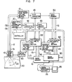
- Fig. 7 shows another embodiment of this invention, where the read-in processes of the longitudinal and transverse ultrasonic wave signals are forced to occur simultaneously. Therefore, a higher speed data processing can be done with use of the components having the same performance.
- the apparatus shown in Fig. 7 does not contain any multiplexer, and the transmitting/receiving sections (30,13), A/D converters (45, 46), wave memories (50, 53), distance arithmetic unit sections (70, 17), synthesizing arithmetic unit sections (60, 16), and image memories (90, 19) have a dual structure.
- Exclusive buses 51 and 52 are provided as the data transfer buses from the wave memories 50 and 53 to synthesizing arithmetic unit sections 60 and 16, respectively.
- Hardware constitution is formed in such a manner that the synthesizing arithmetic unit sections 60 and 16 and the image memories 90 and 19 act cooperatively.
- An image processing section 25 selects or unites the images obtained by the synthesizing arithmetic unit sections 60 and 16, and displays either an image of longitudinal wave or an image of transverse wave, or a synthesized image of the both images on the display section 95.
Description
- This invention relates to an ultrasonic synthetic aperture testing apparatus according to the preambles of
claim 1 and 4, respectively. - An ultrasonic synthetic aperture testing apparatus according to the preambles of
claim 1 and 4 is known from Proc. IEEE 67 (4), PP. 510-525, April 1979. - The synthetic aperture method is known as a method for enhancing the direction resolution, which expresses the ability of discriminating between two objects under testing (e.g. a flaw in a steel material). According to this method, information is obtained as follows. Namely, ultrasonic waves are transmitted and received at multiple points, and all these signals are synthesized in such a manner that the phases of the received signals obtained at these points coincide with each other.
- The direction resolution 6 of the synthetic aperture testing apparatus is expressed as δ=λ/φ, where 0 is the angle subtended by the transmission-reception region (aperture) seen toward a reflection body (a to-be-tested object). The direction resolution becomes higher as 6 is smaller. Therefore, recently, an ultrasonic wave probe with a large value of 0 is used. With use of spherical vibrators, the focus is placed on a position of the surface of a steel material. However, as will be mentioned later, as the refraction angle of the ultrasonic wave becomes larger, the sensitivity of this prior art apparatus decreases. This causes a limit on the angle (p. However, a further improvement has been needed in the direction resolution of the synthetic aperture testing apparatus.
- In the proceedings IEEE 67 (4) the known apparatus is disclosed in an article "Acoustic imaging for Nondestructure Evaluation" by Gordon S. Kino discussing the application of acoustic imaging techniques to nondestructive testing of materials. However, this reference is silent as to the use of at least two vibrators for generation of longitudinal and transverse waves and accumulation by accumulating means of received signals corresponding to the distances between multiple points and a reproduction point in a desired region of the to-be-tested object.
- US-A-3 996 792 discloses the use of transverse and longitudinal waves for ultrasonic wave flaw detection. This known apparatus fails to show a combination of a synthetic aperture technic with the use of the transverse and longitudinal waves. Further the transducer is for generating an ultrasonic wave beam of the narrow directivity pattern whereby according to an embodiment of the present invention the first and second vibrator units are provided on a spherical surface of the ultrasonic probe.
- Accordingly, it is an object of the present invention to provide an ultrasonic synthetic aperture testing apparatus having a high sensitivity even with a large aperture φ and has a high direction resolution 6.
- A solution of the above object is achieved by an ultrasonic synthetic aperture testing apparatus comprising transmitting/receiving sections having an ultrasonic probe transmitting and receiving ultrasonic waves at multiple points on the surface of an object to be tested, an operation section including means accumulating the received signals corresponding to the distances between said multiple points and a reproduction point in a desired region of said object, and a display section which displays an image formed by the result of an accumulation operation by said accumulating means, which is, according to the invention, characterized in that said ultrasonic probe includes at least two vibrators corresponding to different vibration modes transmitting and receiving two kinds of ultrasonic waves in different vibration modes, and said accumulating means are arranged to accumulate signals corresponding to said two kinds of waves in the different vibration modes.
- According to an advantageous development thereof said accumulating means include controller means for varying parameters for said accumulation operation in accordance with the propagation velocities of said two kinds of waves.
- According to a further advantageous development thereof said accumulating means include a plurality of calculation means, each calculation means corresponding to each of said vibration modes and a controller means driving said calculation means separately.
- A further solution of the object is achieved by an ultrasonic synthetic aperture testing apparatus comprising transmitting/receiving means including an ultrasonic probe movable on a surface of an object to be tested for transmitting and receiving ultrasonic waves at multiple points on the surface of the object, operation means for synthesising the received signals corresponding to the distances between the multiple points and a reproduction point in a desired region of the object, and display means for displaying an image formed in accordance with a synthesizing operation of the operation means, which is, according to the invention, characterized in that the ultrasonic probe includes a first vibrator unit producing a first type of ultrasonic wave and a second vibrator unit producing a different second type of ultrasonic wave, the first and second vibrator units being arranged with respect to the object to be tested so that the first and second vibrator units transmit the first and second types of waves, respectively, into the object at different incident angles, and the operation means are arranged to be responsive to the received first and second types of ultrasonic waves for synthesizing signals indicative thereof, whereby the display means display an image in accordance with the output of the operation means.
- According to advantageous developments thereof the first and second vibrator units produce the first and second ultrasonic waves, respectively, having different sound velocities in the object to be tested;
- the first vibrator unit produces a longitudinal ultrasonic wave and the second vibrator unit produces a transverse ultrasonic wave, the first vibrator unit being disposed for transmitting the longitudinal ultrasonic wave into the object at incident angles smaller than the incident angles at which the second vibrator unit transmits the transverse ultrasonic wave into the object;
- the first and second vibrator units are disposed on a spherical surface of the ultrasonic probe;
- the operation means include means varying parameters for the synthesizing operation in accordance with the different propagation velocities of the longitudinal and transverse waves; and
- the transmitting/receiving means include a first transmitting and receiving unit for transmission and reception of the longitudinal ultrasonic wave and a second transmitting and receiving unit for transmission and reception of the transverse ultrasonic wave.
- The present invention will be made more apparent from the following detailed description taken in conjunction with the accompanying drawings, in which:
- Figs. 1 to 3 are explanatory diagrams showing the background principle of this invention;
- Fig. 4 is a block diagram of one embodiment of this invention;
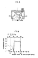
- Fig. 5 is a diagram showing the detailed structure of an ultrasonic wave probe as used in this invention;
- Fig. 6 is an explanatory diagram showing the principle of the ultrasonic wave probe shown in Fig. 5; and
- Fig. 7 is a block diagram showing another embodiment of this invention.
- Before the explanation of the embodiments of this invention, a brief explanation will be made of an example where the synthetic aperture method is applied to an ultrasonic wave testing apparatus. Reference is made to Figs. 1 to 3.
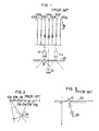
- In Fig. 1, an
ultrasonic wave probe 10 and flaw detection signals 100a to 100g are shown. These are the signals reflected from a to-be-tested object 20, determined by the scanning method and the scanning position of the probe. Here, scanning of theultrasonic wave probe 10 is one dimensional along the direction of x axis and reproduction of image is done in the tomographic way. In theultrasonic wave probe 10, vibrators with a short focal point converging surface are used in order that transmission and reception of ultrasonic waves of an acousticdiscontinuous part 21 in anobject 20 to be tested, may occur in an as wide as possible scan region. Namely, the ultrasonic waves are focused on a focal point and thereafter diffused toward theobject 20, whereby the above-mentioned function is realized. The presence of theacoustic discontinuity 21 in the to-be-tested object yields the ultrasonic flaw detection signals 100a to 100g. - The procedure for obtaining a tomographic image from the ultrasonic flaw detection signals will be explained next with reference to Fig. 2. Positions of the ultrasonic wave probe corresponding to the ultrasonic flaw detection signals 100a to 100g are denoted as 101 a to 101 g, respectively. Let us consider the formation of an image of the
reproduction point 23 corresponding to the acoustic discontinuity 21 (see Fig. 1) of the to-be-testedobject 20. The distance between the position 101 a of the ultrasonic wave probe and the reproduction point is measured. The propagation time is calculated from the sound velocity in the to-be-tested object. Using this propagation time, a signal for the image data is derived from the ultrasonic flaw detection signal 100a. Similar operations are performed for the ultrasonicflaw detection signals 100b to 100g, and these image data are accumulated. This completes the image formation of thereproduction point 23. Next, the above operation is performed for each point in the tomographic image. This procedure enables the tomographic image reproduction using the synthetic aperture method. The data of the detection signal 100a are superimposed on the image data of the points lying at an equi-distance from the position 101a of the ultrasonic wave probe. Data on the other points are superimposed in the same way, whereby the image of thereproduction point 23 corresponding to theacoustic dislocation 21 is obtained. - The image formation process using the synthetic aperture method will be explained by using mathematical equations with reference to Fig. 3. We assume that the
ultrasonic wave probe 10 is scanned in the direction of x-axis and that the image reproduction is tomographic in the x-z plane. A point (xo, zo) in the x-z plane means that its coordinate is given by x=xo, z=zo. The coordinate of the ultrasonic wave probe is given by (xo, 0), and the to-be-tested object situates in the region of z?0. The coordinate of areproduction point 23 within the region of the to-be-tested object is given by (x" z,). Theultrasonic wave probe 10 transmits a wave expressed as follows at a time t. - St(t)=u(t)sin(2πfot)
- Fig. 4 shows a whole constitution of one embodiment of this invention. An
ultrasonic wave probe 10 is scanned either manually or automatically on the surface of the to-be-tested object. Before the explanation of the whole constitution, the structure of the probe used in this invention will be described. The structure of theultrasonic wave probe 10 is shown in Fig. 5. 14L denotes a longitudinal wave vibrator while 14S denotes a transverse wave vibrator. Both vibrators are shown disposed on the same spherical surface. However, it is not always necessary that the distances from thecenter 0 to both vibrators are equal to each other. Let us refer to Fig. 6 in order to understand the positional relation between the vibrators. Fig. 6 shows the "turnaround" sound pressure transmission rate vs. the incident angle θi of an ultrasonic wave beam incident on a steel material (longitudinal sound wave velocity V,=5,850 m/s, transverse sound wave velocity VS=3,230 m/s) through an acrylic resin shoe 15 (longitudinal sound wave velocity V°=2,720 m/s) in which ultrasonic waves go forward through and return backward through the steel material. Abscissae θlr and θsr denote refraction angles of the longitudinal and transverse waves, respectively. The solid curve represents the transverse wave, while the broken curve represents the longitudinal wave. The figure indicates the following fact. In the range of small θi, the longitudinal wave contributes primarily to the ultrasonic wave signal. With an increase in 8,, the transmission rate of the longitudinal wave decreases and the contribution of the transverse wave gradually increases. Finally, only the transverse wave contributes to the signal. In the ultrasonic wave probe shown in Fig. 5, thelongitudinal wave vibrator 14L and thetransverse wave vibrator 14S are made to have the following characteristic, - 15°≦θ1≦20°,
- 30°≦θt1≦35°,
- 50°≦θt2≦57°.
- The waveform data stored in the
wave memory 50 are transferred to amemory 113 in a controller 11 through a bus 111. The controller 11 is controlled by aCPU 115 constituted by a microcomputer, etc. Next, explanation will be made of the operation of the controller 11. - The waveform data stored in the
wave memory 50 are read out sequentially byCPU 115. The data thus read out are compared with a threshold level of the data which are preliminarily read. Those data which exceed this threshold level are processed in the following way. - Assume that the threshold level of the waveform data is STH. Of the waveform data Sr(xr, t) of a received signal at a position xr of the ultrasonic wave probe, those data Sr(xr, t,) which satisfy

image memory 90 is calculated from the following equation.
keyboard 112 into the memory. After the position x, of the ultrasonic wave probe is transferred to a distancearithmetic unit section 70 through the bus 111, the value of R, obtained through eq. (4) is transferred to the distancearithmetic unit section 70 through the bus 111. - The waveform data Sr(xr, ti) is transferred to a synthesizing
arithmetic unit section 60 through the bus 111. After the above-mentioned data setting, a start signal is sent to the distancearithmetic unit section 70 from the controller 11 through the bus 111. In synchronization with the start signal, the coordinate of the image memory 90 (address of the memory) is calculated in order to write the waveform data Sr(x, t;) into the distancearithmetic unit section 70. The waveform data Sr(xr, ti) are written into theimage memory 90 along the locus of a radius Ri, which is expressed by
image memory 90. - In the distance
arithmetic unit section 70, the value of yR corresponding to xR or the coordinate of theimage memory 90, is calculated from eq. (5) to obtain the value of (xR, YR). This is introduced into theimage memory 90 as theimage address data 71. The image data corresponding to this introduced address are . read out from theimage memory 90, and supplied to the synthesizingarithmetic unit section 60. In the synthesizingarithmetic unit section 60, the sum of the preliminarily set waveform data and the image data are calculated. The synthesizeddata 61 are written into theimage memory 90 again. The above-mentioned calculation for synthesis is performed for all points (xR, yR) that satisfy eq. (5). This can be realized with a high speed hardware which starts automatically with a start signal entering the distancearithmetic unit section 70. - If the condition given by eq. (3) is satisfied for one received signal, eq. (4) is calculated and calculation for synthesis is performed for the coordinate (XR, YR) as determined by eq. (5). For every one position x, of the ultrasonic wave probe, the above calculation is done for two signals of longitudinal and transverse waves through the same procedure.
- The above-mentioned operation for the position x, of the ultrasonic wave probe is applicable to other positions of the ultrasonic wave probe. When the operation for all the positions of the probe is finished, an image which is formed in the
image memory 90 is displayed on adisplay section 95 in accordance with the program of aprogram storage 114 in the controller 11. If the controller 11 has aCRT 116 provided with a buffer memory for the image, theCRT 116 can also be used as the display. - The whole control is done by the controller 11. The control procedure is executed by an instruction program in the
program memory 114. Next, explanation will be made of the operation of the apparatus following the flow of program. - First, the sound velocities vL, vS, the threshold value STH of the waveform data, and the setting values of the scanning points of the ultrasonic wave probe are supplied from the
keyboard 112. This is the setting of the initial values in the hardware. The initial position x, of scanning of the ultrasonic wave probe is set. A position signal is read into aposition detector 80 and compared with the scanning position x,. When they coincide with each other, the longitudinal ultrasonic wave transmitting/receivingsection 30 is driven, and an ultrasonic wave is generated by theultrasonic wave probe 10. Thereafter, the received signal Sr(xr, t) is stored in thewave memory 50 through themultiplexer 40 and the A/D converter 45. The stored waveform data are introduced into thememory 113 in the controller 11 to execute the above-mentioned process. The distancearithmetic unit section 70, theimage memory section 90 and the synthesizingarithmetic unit section 60 are driven to make the operation for synthesis. The same procedure is taken for the transverse wave. Then, the ultrasonic wave probe is moved and the above-mentioned procedure is repeated. - When the read-in process of all the signals is finished, the image is displayed on the
display section 95 in accordance with the image data of theimage memory 90. - Fig. 7 shows another embodiment of this invention, where the read-in processes of the longitudinal and transverse ultrasonic wave signals are forced to occur simultaneously. Therefore, a higher speed data processing can be done with use of the components having the same performance. The apparatus shown in Fig. 7 does not contain any multiplexer, and the transmitting/receiving sections (30,13), A/D converters (45, 46), wave memories (50, 53), distance arithmetic unit sections (70, 17), synthesizing arithmetic unit sections (60, 16), and image memories (90, 19) have a dual structure.
Exclusive buses wave memories arithmetic unit sections 60 and 16, respectively. Hardware constitution is formed in such a manner that the synthesizingarithmetic unit sections 60 and 16 and theimage memories image processing section 25 selects or unites the images obtained by the synthesizingarithmetic unit sections 60 and 16, and displays either an image of longitudinal wave or an image of transverse wave, or a synthesized image of the both images on thedisplay section 95.


Let us refer to Fig. 4 again. The transmission and the reception of ultrasonic wave signals are done at preliminarily specified positions of the ultrasonic wave probe. The operation of transmission and reception is performed once for longitudinal and transverse waves. A longitudinal ultrasonic wave transmitting/ receiving
Claims (9)
Priority Applications (2)
| Application Number | Priority Date | Filing Date | Title |
|---|---|---|---|
| EP19820109646 EP0105966B1 (en) | 1982-10-19 | 1982-10-19 | Ultrasonic testing apparatus |
| DE8282109646T DE3277083D1 (en) | 1982-10-19 | 1982-10-19 | Ultrasonic testing apparatus |
Applications Claiming Priority (1)
| Application Number | Priority Date | Filing Date | Title |
|---|---|---|---|
| EP19820109646 EP0105966B1 (en) | 1982-10-19 | 1982-10-19 | Ultrasonic testing apparatus |
Publications (2)
| Publication Number | Publication Date |
|---|---|
| EP0105966A1 EP0105966A1 (en) | 1984-04-25 |
| EP0105966B1 true EP0105966B1 (en) | 1987-08-26 |
Family
ID=8189290
Family Applications (1)
| Application Number | Title | Priority Date | Filing Date |
|---|---|---|---|
| EP19820109646 Expired EP0105966B1 (en) | 1982-10-19 | 1982-10-19 | Ultrasonic testing apparatus |
Country Status (2)
| Country | Link |
|---|---|
| EP (1) | EP0105966B1 (en) |
| DE (1) | DE3277083D1 (en) |
Families Citing this family (5)
| Publication number | Priority date | Publication date | Assignee | Title |
|---|---|---|---|---|
| DE3715914A1 (en) * | 1987-05-13 | 1988-12-01 | Fraunhofer Ges Forschung | Method and apparatus for detecting cracks with the aid of ultrasound |
| DE9214948U1 (en) * | 1992-11-03 | 1994-03-10 | Siemens Ag | Ultrasonic transducer arrangement |
| DE102013200974A1 (en) | 2013-01-22 | 2014-07-24 | Siemens Aktiengesellschaft | Method and system for hand-held ultrasonic testing of a test object |
| DE102013201975A1 (en) | 2013-02-07 | 2014-08-07 | Siemens Aktiengesellschaft | Method and device for improving SAFT analysis in case of irregular measurement |
| JP6992678B2 (en) * | 2018-05-31 | 2022-01-13 | Jfeスチール株式会社 | Ultrasonic flaw detection method, ultrasonic flaw detector, steel manufacturing equipment line, steel manufacturing method, and steel quality assurance method |
Family Cites Families (4)
| Publication number | Priority date | Publication date | Assignee | Title |
|---|---|---|---|---|
| JPS5311473B2 (en) * | 1974-07-03 | 1978-04-21 | ||
| US4058001A (en) * | 1976-08-02 | 1977-11-15 | G. D. Searle & Co. | Ultrasound imaging system with improved scan conversion |
| AU523895B2 (en) * | 1978-08-04 | 1982-08-19 | Commonwealth Of Australia, The | Ultrasonic echoscope |
| JPS5644842A (en) * | 1979-09-21 | 1981-04-24 | Hitachi Ltd | Ultrasonic probe |
-
1982
- 1982-10-19 DE DE8282109646T patent/DE3277083D1/en not_active Expired
- 1982-10-19 EP EP19820109646 patent/EP0105966B1/en not_active Expired
Also Published As
| Publication number | Publication date |
|---|---|
| DE3277083D1 (en) | 1987-10-01 |
| EP0105966A1 (en) | 1984-04-25 |
Similar Documents
| Publication | Publication Date | Title |
|---|---|---|
| US4481822A (en) | Synthetic aperture ultrasonic testing apparatus with shear and longitudinal wave modes | |
| US5840033A (en) | Method and apparatus for ultrasound imaging | |
| EP0168565B1 (en) | Ultrasonic measurement method and apparatus therefor | |
| CN102652678A (en) | Ultrasound diagnostic apparatus, method of transmitting and receiving ultrasonic wave, and program for transmitting and receiving ultrasonic wave | |
| EP0642036A2 (en) | Ultrasonic diagnostic equipment | |
| JP2001187054A (en) | Numerical optimization of ultrasound beam path | |
| US4252026A (en) | Multiple line of sight ultrasonic apparatus | |
| CA1240786A (en) | Ultrasonic imaging device | |
| US4862892A (en) | Ultrasonic reflex transmission imaging method and apparatus with artifact removal | |
| US4688430A (en) | Device for imaging three dimensions with a single pulse transmission | |
| EP0105966B1 (en) | Ultrasonic testing apparatus | |
| EP0293803B1 (en) | Fan-shape scanning ultrasonic flaw detecting apparatus | |
| EP0421279A1 (en) | Ultrasonic diagnostic apparatus with selective focussing patterns | |
| JPH0244394B2 (en) | ||
| CA1190312A (en) | Ultrasonic testing apparatus | |
| JPH07236642A (en) | Ultrasonic diagnostic device | |
| JPH0364831B2 (en) | ||
| JP2672123B2 (en) | Ultrasonic microscope | |
| JP3101301B2 (en) | Ultrasound diagnostic equipment | |
| JP2784788B2 (en) | Ultrasound diagnostic equipment | |
| JP2643318B2 (en) | 3D object shape recognition method using ultrasonic waves | |
| KR100543736B1 (en) | Ultrasonic imaging method | |
| JP2859916B2 (en) | Echo signal processing device and underwater detection device including the same | |
| JPH0440360A (en) | Ultrasonic flaw detecting method for composite material | |
| JPS60242365A (en) | Ultrasonic inspecting device |
Legal Events
| Date | Code | Title | Description |
|---|---|---|---|
| PUAI | Public reference made under article 153(3) epc to a published international application that has entered the european phase |
Free format text: ORIGINAL CODE: 0009012 |
|
| AK | Designated contracting states |
Designated state(s): DE FR GB IT |
|
| 17P | Request for examination filed |
Effective date: 19840426 |
|
| GRAA | (expected) grant |
Free format text: ORIGINAL CODE: 0009210 |
|
| AK | Designated contracting states |
Kind code of ref document: B1 Designated state(s): DE FR GB IT |
|
| RBV | Designated contracting states (corrected) |
Designated state(s): DE FR GB |
|
| REF | Corresponds to: |
Ref document number: 3277083 Country of ref document: DE Date of ref document: 19871001 |
|
| ET | Fr: translation filed | ||
| PLBE | No opposition filed within time limit |
Free format text: ORIGINAL CODE: 0009261 |
|
| STAA | Information on the status of an ep patent application or granted ep patent |
Free format text: STATUS: NO OPPOSITION FILED WITHIN TIME LIMIT |
|
| 26N | No opposition filed | ||
| PGFP | Annual fee paid to national office [announced via postgrant information from national office to epo] |
Ref country code: DE Payment date: 19911217 Year of fee payment: 10 |
|
| PGFP | Annual fee paid to national office [announced via postgrant information from national office to epo] |
Ref country code: FR Payment date: 19920814 Year of fee payment: 11 |
|
| PGFP | Annual fee paid to national office [announced via postgrant information from national office to epo] |
Ref country code: GB Payment date: 19921009 Year of fee payment: 11 |
|
| PG25 | Lapsed in a contracting state [announced via postgrant information from national office to epo] |
Ref country code: DE Effective date: 19930701 |
|
| PG25 | Lapsed in a contracting state [announced via postgrant information from national office to epo] |
Ref country code: GB Effective date: 19931019 |
|
| GBPC | Gb: european patent ceased through non-payment of renewal fee |
Effective date: 19931019 |
|
| PG25 | Lapsed in a contracting state [announced via postgrant information from national office to epo] |
Ref country code: FR Effective date: 19940630 |
|
| REG | Reference to a national code |
Ref country code: FR Ref legal event code: ST |