EP0105265B1 - An anchor bolt - Google Patents
An anchor bolt Download PDFInfo
- Publication number
- EP0105265B1 EP0105265B1 EP82902534A EP82902534A EP0105265B1 EP 0105265 B1 EP0105265 B1 EP 0105265B1 EP 82902534 A EP82902534 A EP 82902534A EP 82902534 A EP82902534 A EP 82902534A EP 0105265 B1 EP0105265 B1 EP 0105265B1
- Authority
- EP
- European Patent Office
- Prior art keywords
- sleeve
- rod
- expansion body
- head
- outer sleeve
- Prior art date
- Legal status (The legal status is an assumption and is not a legal conclusion. Google has not performed a legal analysis and makes no representation as to the accuracy of the status listed.)
- Expired
Links
- 239000000463 material Substances 0.000 claims description 19
- 125000006850 spacer group Chemical group 0.000 claims description 14
- 230000004048 modification Effects 0.000 description 4
- 238000012986 modification Methods 0.000 description 4
- 239000007787 solid Substances 0.000 description 4
- 238000011065 in-situ storage Methods 0.000 description 2
- 238000004519 manufacturing process Methods 0.000 description 2
- 229920003023 plastic Polymers 0.000 description 2
- 239000004033 plastic Substances 0.000 description 2
- 238000004873 anchoring Methods 0.000 description 1
- 230000007812 deficiency Effects 0.000 description 1
- 230000000694 effects Effects 0.000 description 1
- 239000002184 metal Substances 0.000 description 1
- 230000000717 retained effect Effects 0.000 description 1
- 238000004901 spalling Methods 0.000 description 1
Images

Classifications
-
- F—MECHANICAL ENGINEERING; LIGHTING; HEATING; WEAPONS; BLASTING
- F16—ENGINEERING ELEMENTS AND UNITS; GENERAL MEASURES FOR PRODUCING AND MAINTAINING EFFECTIVE FUNCTIONING OF MACHINES OR INSTALLATIONS; THERMAL INSULATION IN GENERAL
- F16B—DEVICES FOR FASTENING OR SECURING CONSTRUCTIONAL ELEMENTS OR MACHINE PARTS TOGETHER, e.g. NAILS, BOLTS, CIRCLIPS, CLAMPS, CLIPS OR WEDGES; JOINTS OR JOINTING
- F16B13/00—Dowels or other devices fastened in walls or the like by inserting them in holes made therein for that purpose
- F16B13/04—Dowels or other devices fastened in walls or the like by inserting them in holes made therein for that purpose with parts gripping in the hole or behind the reverse side of the wall after inserting from the front
- F16B13/045—Dowels or other devices fastened in walls or the like by inserting them in holes made therein for that purpose with parts gripping in the hole or behind the reverse side of the wall after inserting from the front having axially compressing parts allowing the clamping of an object tightly to the wall
Definitions
- the invention relates to an anchor bolt of the type defined in the preamble of claim 1.
- a prior art anchor bolt of this type is shown in FR-A-2362299.
- An anchor- bolt described therein has a screw-threaded bolt 6 carrying on its threads a frusto-conical expansion body 10 which engages in a longitudinally split expansion sleeve 11 for anchoring the bolt in a hole.
- a plastic socket 13 which is collapsed longitudinally on anchorage in the hole. Collapsing of the socket 13 means that the sleeve 11 can be over-expanded with consequent spalling of the material surrounding the hole.
- the arrangement defined in Claim 1 obviates the deficiencies of the prior art anchor in that the distance between the abutment on the expansion body and the head of the rod progressively reduces from the moment the anchor rod is turned in the expansion body first to set the expansion sleeve to the required torque, and then to reduce further axially until the object to be clamped is brought firmly against the receiving material and the sleeve occupies or substantially occupies the distance between the abutments.
- a solid or substantially solid body is formed between the internal surface of the socket and the body of the anchor rod thereby providing the required ability to withstand high shear loads, while the induced load in the bolt from the torque tightening, remains substantially to clamp down the fixture and hence maximise the anti-vibration efficiency.
- the spacer means is a coiled spring held between the abutment on the expansion body and the rod head.
- the spacer means may comprise a pair of spacer sleeves one of which is press-fit within the outer sleeve and in abutment with the anchor head, the other spacer sleeve being arranged for slidable movement within the outer sleeve as the distance between the abutments is reduced.
- the outer sleeve and the first and second spacer sleeves are preferably longitudinally split tubes, the second spacer sleeve abutting the abutment on the expansion body and of lesser outside diameter than the outside diameter of the first spacer sleeve which is positioned within the outer sleeve in press-fit engagement.
- the outer sleeve is tapered, with its maximum diameter being adjacent the head of the rod and of slightly greater diameter than the receiving socket.
- the outer sleeve is firmly engaged in the socket at the position of maximum taper so preventing the sleeve falling out of the socket when the anchor bolt is used in an overhead application, or if the rod is removed after the anchor has been set.
- the anchor bolt shown in Figure 1 comprises a threaded anchor rod 1 having a head portion 2 shaped to enable torque to be applied to the rod when setting the anchor bolt.
- An expansion body 3 is threadedly received on the anchor rod 1 and has a leading circular head portion 4, a trailing circular head portion 5 and a waisted portion 6 between the head portions 4 and 5 which tapers towards the head 2 of the anchor rod 1.
- An expansible tubular split sleeve 7 is mounted on the waisted portion 6 and is of substantially the same diameter as the head portions 4 and 5.
- the anchor bolt as above described operates when used to clamp an object such as a profiled beam to receiving material, as follows.
- a socket of the diameter of the head portions 4 and 5, the sleeve and the plain tube 10, is first drilled in a receiving material.
- a similar hole is drilled, or pre-drilled, through the object to be clamped.
- the anchor bolt is then inserted through the hole in the object to be clamped and tapped home in the socket.
- Application of torque to the head 2 of the anchor 1 causes the expansion body 3 to be drawn axially of the anchor rod 1 thereby expanding the sleeve 7 into gripping contact with the socket to thereby set the anchor bolt.
- Axial movement of the expansion body 3 during this torquing-up action correspondingly reduces the distance between the head portion 5 and the end of the sleeve 10, and compresses the spring 8.
- the sleeve 10 is longitudinally dimensioned so that subsequent rotation of the anchor rod 1 in the expansion body 3 further reduces the distance between the sleeve 10 and the abutment 5 until the object to to clamped is firmly held against the receiving material, at which point, the end of the sleeve 10 is in contact with or preferably almost in contact with the abutment or head portion 5.
- the combination of the sleeve 10 and the compressed spring 8, spaced between the sleeve and the shank of the anchor rod 1, in the set condition of the fixing provides the anchor with the ability to withstand high shear loads. This coupled with the fact that the object to be clamped is held firmly against the bare material provides all the advantages which the prior art does not possess.
- any torque loading applied to the anchor rod 1 in an effort to achieve this end does not go to otherwise uselessly loading the sleeve 10 as with the prior art device, but rather to improve the gripping action of the anchor rod by introducing stress forces acting between the head of the anchor rod 1 and the expansion body 6 through the bare material and along the rod itself to the expansion body 3, and thus between it and the sleeve 7. In this way the anti-vibrational properties of the fixing as a whole are maximised.
- the anchor bolt shown in Figure 2 is a modification of the anchor bolt shown in Figure 1, the modification being exemplified in the cross-sectional view of the bolt shown.
- those parts in common with the embodiment of Figure 1 will be given like reference numerals.
- the inner split sleeve 11 is in friction fit with an outer longitudinally split tubular sleeve 12 of greater longitudinal extent along the axis of the rod 1 than the inner sleeve 11, and positioned over the coiled spring 8.
- the arrangement of the longitudinal splits 11' and 12' in the sleeves 11 and 12 is shown in the cross-sectional view through the split sleeve assembly in Figure 2.
- the splits 11' and 12' are arranged to be diametrically opposed as shown although this is not essential.
- the splits 11' and 12' are introduced so that the sleeves 11 and 12 may be made from strip material and to improve the interference fit between the two sleeves since any variation in diameter is taken up by the induced resilience of the respective split sleeves.
- the embodiment shown in Figure 4 removes these dangers by dispensing with the coiled spring and introducing an additional inner longitudinally split tubular sleeve 14 movable within the outer tubular sleeve 12. This is shown clearly in the cross-sectional view shown in Figure 4.
- the lengths of the sleeves 11 and 14 are such that when the anchor bolt is fully torqued-up and the object to be clamped is firmly against the receiving material, the sleeves 11 and 14 are in abutment, or substantially so, within the outer sleeve 12 thus introducing solidity between the wall of the socket and the anchor rod 1.
- the additional sleeve 14 is of lesser diameter that the inner sleeve 11 such that the outer sleeve 12 forms a tapered configuration the tapering direction being towards the expansion body 3.
- the diameter of the inner sleeve 11 is such that the diameter of the outer sleeve 12 at this point is a little greater than the diameter of the drilled receiving socket. In this way when the anchor bolt is tapped home in the socket the sleeve is held in friction grip in the socket so that it will not fall out of the socket in an overhead application, upon removal of the anchor rod 1.
- the additional sleeve 14 of Figure 4 is provided with a mid-section belled-out portion 15 so that as the outer sleeve 12 moves over the surface of the additional sleeve 14 it is wedged outwardly into gripping contact with the receiving socket.
- This arrangement comprises two longitudinally split outer tubular sleeves 15 and 16 spaced from one another and each being in abutment respectively with the head 2 of the bolt 1 and the head portion 5 of the expansible body 3.
- a shorter split inner tubular sleeve 17 is held in press-fit engagement at the end of the sleeve 15 and in abutment with the washer 9 or head 2 of the anchor rod 1, while a split inner tubular sleeve 18 of similar dimensions is held in press-fit engagement within the outer sleeve 16 and in abutment with the head portion 5.
- a further split inner tubular sleeve 19 for sliding movement within the outer sleeves 15 and 16, is situated centrally between the head portion 5 and the washer 9 or head 2, as shown.
- the relative dimensions of the inner sleeves 17, 18 and 19 is such that with the bolt fully torqued-up and the object to be clamped held hard against the receiving material, the sleeves 15, 16 abut or substantially abut one another, and the sleeve 19 is both in abutment with the sleeves 17 and 18, thereby forming a solid or nearly solid piece of material between the receiving socket and the anchor rod 1.
- the centrally situated inner sleeve 19 can be modified according to the sleeve 15 of the embodiment of Figure 5 and of lesser diameter at its entrant portions into the sleeves 15 and 16, to provide the tapering effect of the sleeves 15 and 16 as required.
- FIG. 7 An anchor bolt of the type as described in Figure 4 is shown in-situ in Figure 7.
- the position shown corresponds to an arrangement of anchor bolt parts, prior to torquing-up the anchor rod 1.
- the anchor bolt has been tapped through the hole in the object to be clamped S, is received in the receiving socket R, and a distance D exists between the abutment formed by the expansion body 3 and the end of the outer sleeve 12.
- the expansion body 3 moves axially up to the anchor rod 1 to reduce the distance D while at the same time the sleeve 7 is moved into gripping contact with the socket R.
- the material used for the collapsible sleeve arrangements of the. devices as above described may be made of a metal or of plastics.
Landscapes
- Engineering & Computer Science (AREA)
- General Engineering & Computer Science (AREA)
- Mechanical Engineering (AREA)
- Dowels (AREA)
- Joining Of Building Structures In Genera (AREA)
Description
- The invention relates to an anchor bolt of the type defined in the preamble of
claim 1. - A prior art anchor bolt of this type is shown in FR-A-2362299. An anchor- bolt described therein has a screw-threaded
bolt 6 carrying on its threads a frusto-conical expansion body 10 which engages in a longitudinally splitexpansion sleeve 11 for anchoring the bolt in a hole. Between thesleeve 11 and abrace 14 adjacent the head of thebolt 6 there is aplastic socket 13 which is collapsed longitudinally on anchorage in the hole. Collapsing of thesocket 13 means that thesleeve 11 can be over-expanded with consequent spalling of the material surrounding the hole. - It is an object of the invention therefore to remove the disadvantages of the prior art by providing an anchor bolt which while having the ability to withstand high shear loads, ensures that the object being clamped is pulled down against the bare material so that the fixing is able to withstand vibrational loads.
- According to the invention this object is achieved by the features set out in the characterising part of
claim 1. - The arrangement defined in
Claim 1 obviates the deficiencies of the prior art anchor in that the distance between the abutment on the expansion body and the head of the rod progressively reduces from the moment the anchor rod is turned in the expansion body first to set the expansion sleeve to the required torque, and then to reduce further axially until the object to be clamped is brought firmly against the receiving material and the sleeve occupies or substantially occupies the distance between the abutments. - Moreover the fact that the spacer means is between the outer sleeve and the anchor rod in the anchored or set position, a solid or substantially solid body is formed between the internal surface of the socket and the body of the anchor rod thereby providing the required ability to withstand high shear loads, while the induced load in the bolt from the torque tightening, remains substantially to clamp down the fixture and hence maximise the anti-vibration efficiency.
- Preferably the spacer means is a coiled spring held between the abutment on the expansion body and the rod head.
- Alternatively the spacer means may comprise a pair of spacer sleeves one of which is press-fit within the outer sleeve and in abutment with the anchor head, the other spacer sleeve being arranged for slidable movement within the outer sleeve as the distance between the abutments is reduced.
- The outer sleeve and the first and second spacer sleeves are preferably longitudinally split tubes, the second spacer sleeve abutting the abutment on the expansion body and of lesser outside diameter than the outside diameter of the first spacer sleeve which is positioned within the outer sleeve in press-fit engagement. The outer sleeve is tapered, with its maximum diameter being adjacent the head of the rod and of slightly greater diameter than the receiving socket.
- In this way, with the anchor bolt fully tapped home in the socket prior to torquing-up, the outer sleeve is firmly engaged in the socket at the position of maximum taper so preventing the sleeve falling out of the socket when the anchor bolt is used in an overhead application, or if the rod is removed after the anchor has been set.
- Other features and advantages of the present invention will become apparent from the description that follows.
- Embodiments of the present invention will now be described by way of example with reference to the accompanying drawings wherein:
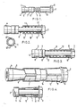
- Figure 1 is a view of an anchor bolt according to an embodiment of the invention;
- Figure 2 is a cross-sectional view of an anchor bolt according to another embodiment of the invention and includes a sectional view through the split tube assembly of the bolt;
- Figure 3 is a cross-sectional view through an anchor bolt according to another embodiment of the invention;
- Figure 4 shows an anchor bolt according to a further embodiment of the invention and includes a cross-sectional view through the bolt;
- Figure 5 shows a part cross-sectional view through an anchor bolt according to another embodiment of the invention;
- Figure 6 is a cross-sectional view through an anchor bolt according to a still further embodiment of the invention; and
- Figure 7 shows the anchor bolt of Figure 4 mounted in-situ and clamping an object to bare material.
- The anchor bolt shown in Figure 1 comprises a threaded
anchor rod 1 having ahead portion 2 shaped to enable torque to be applied to the rod when setting the anchor bolt. - An
expansion body 3 is threadedly received on theanchor rod 1 and has a leading circular head portion 4, a trailingcircular head portion 5 and a waistedportion 6 between thehead portions 4 and 5 which tapers towards thehead 2 of theanchor rod 1. - An expansible
tubular split sleeve 7 is mounted on the waistedportion 6 and is of substantially the same diameter as thehead portions 4 and 5. - The
head portion 5, and thehead 2 of theanchor rod 1, form abutments between which is held acoiled spring 8. Normally awasher 9 is interposed between thespring 8 and thehead portion 2 as shown. - A plain
tubular sleeve 10 of the same diameter as theportions 4 and 5 andsleeve 7, is mounted over a portion of thespring 8 and in abutment with thewasher 9. - The anchor bolt as above described operates when used to clamp an object such as a profiled beam to receiving material, as follows.
- A socket of the diameter of the
head portions 4 and 5, the sleeve and theplain tube 10, is first drilled in a receiving material. A similar hole is drilled, or pre-drilled, through the object to be clamped. - The anchor bolt is then inserted through the hole in the object to be clamped and tapped home in the socket. Application of torque to the
head 2 of theanchor 1 causes theexpansion body 3 to be drawn axially of theanchor rod 1 thereby expanding thesleeve 7 into gripping contact with the socket to thereby set the anchor bolt. Axial movement of theexpansion body 3 during this torquing-up action correspondingly reduces the distance between thehead portion 5 and the end of thesleeve 10, and compresses thespring 8. Thesleeve 10 is longitudinally dimensioned so that subsequent rotation of theanchor rod 1 in theexpansion body 3 further reduces the distance between thesleeve 10 and theabutment 5 until the object to to clamped is firmly held against the receiving material, at which point, the end of thesleeve 10 is in contact with or preferably almost in contact with the abutment orhead portion 5. - The combination of the
sleeve 10 and thecompressed spring 8, spaced between the sleeve and the shank of theanchor rod 1, in the set condition of the fixing provides the anchor with the ability to withstand high shear loads. This coupled with the fact that the object to be clamped is held firmly against the bare material provides all the advantages which the prior art does not possess. - Moreover since the
sleeve 10 does not come into contact with thehead portion 5 before the object to be clamped is firmly held against the receiving material, any torque loading applied to theanchor rod 1 in an effort to achieve this end, does not go to otherwise uselessly loading thesleeve 10 as with the prior art device, but rather to improve the gripping action of the anchor rod by introducing stress forces acting between the head of theanchor rod 1 and theexpansion body 6 through the bare material and along the rod itself to theexpansion body 3, and thus between it and thesleeve 7. In this way the anti-vibrational properties of the fixing as a whole are maximised. - The anchor bolt shown in Figure 2 is a modification of the anchor bolt shown in Figure 1, the modification being exemplified in the cross-sectional view of the bolt shown. In this example of the invention, as with the further embodiments to be described, those parts in common with the embodiment of Figure 1 will be given like reference numerals.
- Thus in Figure 2 the coiled
spring 8 abuts an inner longitudinally splittubular sleeve 11 interposed between thespring 8 and thewasher 9. - The
inner split sleeve 11 is in friction fit with an outer longitudinally splittubular sleeve 12 of greater longitudinal extent along the axis of therod 1 than theinner sleeve 11, and positioned over the coiledspring 8. - The arrangement of the longitudinal splits 11' and 12' in the
sleeves - The presence of the
inner sleeve 11 while retaining the coiledspring 8 within the assembly, serves to fully support the bolt when in shear. - The splits 11' and 12' are introduced so that the
sleeves - In the embodiment of anchor bolt shown in Figure 3, the whole of the coiled spring between the
head portion 5 and thehead 2 of theanchor rod 1 is enclosed. This is provided by adding an additional tubularinner split sleeve 13 for move- mentwithin the outertubular split sleeve 12 in the embodiment of Figure 2. - While this arrangement reduces the influence of grit entering between the coils of the
spring 8, nevertheless due to the need to make theadditional sleeve 13 of thin section so that the maximum diameter of thespring 8 and the thickness of theouter sleeve 13 may be retained, there is a tendancy for the assembly to seize up during movement such that full travel can not be ensured. - The embodiment shown in Figure 4 removes these dangers by dispensing with the coiled spring and introducing an additional inner longitudinally split
tubular sleeve 14 movable within the outertubular sleeve 12. This is shown clearly in the cross-sectional view shown in Figure 4. The lengths of thesleeves sleeves outer sleeve 12 thus introducing solidity between the wall of the socket and theanchor rod 1. - In the embodiment of Figure 4 the
additional sleeve 14 is of lesser diameter that theinner sleeve 11 such that theouter sleeve 12 forms a tapered configuration the tapering direction being towards theexpansion body 3. - Additionally the diameter of the
inner sleeve 11 is such that the diameter of theouter sleeve 12 at this point is a little greater than the diameter of the drilled receiving socket. In this way when the anchor bolt is tapped home in the socket the sleeve is held in friction grip in the socket so that it will not fall out of the socket in an overhead application, upon removal of theanchor rod 1. - While the arrangement of Figure 4 ensures that a portion of the
outer sleeve 12 is in friction fit with the socket, the modification shown in Figure 5, while retaining the tapering properties of theouter sleeve 12, is designed so that the whole extent of the outer surface of thesleeve 12 is in friction fit with the receiving socket in the fully clamped position of the anchor bolt. - To this end the
additional sleeve 14 of Figure 4 is provided with a mid-section belled-outportion 15 so that as theouter sleeve 12 moves over the surface of theadditional sleeve 14 it is wedged outwardly into gripping contact with the receiving socket. - Due to manufacturing restrictions the length to which the split sleeves of the anchor bolts as described hereinbefore may be made, is restricted. This restriction is overcome by the embodiment shown in Figure 6.
- This arrangement comprises two longitudinally split outer
tubular sleeves head 2 of thebolt 1 and thehead portion 5 of theexpansible body 3. - A shorter split inner
tubular sleeve 17 is held in press-fit engagement at the end of thesleeve 15 and in abutment with thewasher 9 orhead 2 of theanchor rod 1, while a split innertubular sleeve 18 of similar dimensions is held in press-fit engagement within theouter sleeve 16 and in abutment with thehead portion 5. - A further split inner
tubular sleeve 19 for sliding movement within theouter sleeves head portion 5 and thewasher 9 orhead 2, as shown. The relative dimensions of theinner sleeves sleeves sleeve 19 is both in abutment with thesleeves anchor rod 1. - The centrally situated
inner sleeve 19 can be modified according to thesleeve 15 of the embodiment of Figure 5 and of lesser diameter at its entrant portions into thesleeves sleeves - An anchor bolt of the type as described in Figure 4 is shown in-situ in Figure 7. The position shown corresponds to an arrangement of anchor bolt parts, prior to torquing-up the
anchor rod 1. Thus the anchor bolt has been tapped through the hole in the object to be clamped S, is received in the receiving socket R, and a distance D exists between the abutment formed by theexpansion body 3 and the end of theouter sleeve 12. As thehead 2 of theanchor rod 1 is turned theexpansion body 3 moves axially up to theanchor rod 1 to reduce the distance D while at the same time thesleeve 7 is moved into gripping contact with the socket R. When the required setting torque has been achieved the remaining application of effort to theanchor rod 1 forces the object to be clamped S into firm engagement with the receiving material M until the end of theouter sleeve 12 touches, or almost touches, thehead portion 5 of theexpansion body 3 at which time theinner sleeve 14 abuts, or nearly abuts, theinner sleeve 11. - The material used for the collapsible sleeve arrangements of the. devices as above described may be made of a metal or of plastics.
- Further other modifications and variations will be apparent to those skilled in the art which are clearly within the scope of the present inventive disclosure.
- For example manufacturing limitations may be placed on the lengths of sleeves used in the fixings thereby limiting the lengths of the anchor bolt. To overcome this problem, the embodiments for instance shown in Figure 4 or 5, may be modified by dispensing with the
sleeve 11 and having thesleeve 15 of the same length as theouter sleeve 12. Similar considerations apply to the Figure 6 embodiment the main criterion being that throughout the dimensions of the respective sleeves are such that none of the effort imparted to the anchor to achieve a fully torqued-up condition, with the object to be clamped held fast against the bare material, is lost in loading the sleeves. This means that the sleeves must be free to slide relative to one another until the above- mentioned set conditions of the anchor bolt, are achieved.
Claims (5)
Priority Applications (1)
| Application Number | Priority Date | Filing Date | Title |
|---|---|---|---|
| AT82902534T ATE27044T1 (en) | 1982-04-15 | 1982-07-28 | CHANGE BOLT. |
Applications Claiming Priority (2)
| Application Number | Priority Date | Filing Date | Title |
|---|---|---|---|
| GB8211011 | 1982-04-15 | ||
| GB8211011 | 1982-04-15 |
Publications (2)
| Publication Number | Publication Date |
|---|---|
| EP0105265A1 EP0105265A1 (en) | 1984-04-18 |
| EP0105265B1 true EP0105265B1 (en) | 1987-05-06 |
Family
ID=10529722
Family Applications (1)
| Application Number | Title | Priority Date | Filing Date |
|---|---|---|---|
| EP82902534A Expired EP0105265B1 (en) | 1982-04-15 | 1982-07-28 | An anchor bolt |
Country Status (11)
| Country | Link |
|---|---|
| EP (1) | EP0105265B1 (en) |
| CA (1) | CA1253365A (en) |
| DE (1) | DE3276256D1 (en) |
| DK (1) | DK151315C (en) |
| FI (1) | FI75914C (en) |
| GB (1) | GB2119048B (en) |
| IE (1) | IE53250B1 (en) |
| IT (1) | IT1152355B (en) |
| PT (1) | PT75393B (en) |
| WO (1) | WO1983003645A1 (en) |
| ZA (1) | ZA825670B (en) |
Families Citing this family (5)
| Publication number | Priority date | Publication date | Assignee | Title |
|---|---|---|---|---|
| GB8606440D0 (en) * | 1986-03-15 | 1986-04-23 | Johnson Metal Press Workers Lt | Fastening device |
| GB2201214B (en) * | 1987-02-13 | 1990-12-19 | Dom Holdings Plc | Expansion anchor |
| JPH0446211A (en) * | 1990-06-06 | 1992-02-17 | Shinjiyou Seisakusho:Yugen | Anchor bolt having spring |
| DE10308807A1 (en) * | 2003-02-27 | 2004-09-09 | Janicon Ag | Anchor for temporarily holding loads, e.g. walls, in position comprises spring-loaded bolt which is normally locked in sleeve but can be released when in position, together with retaining barbs on its end |
| GB2590410B (en) * | 2019-12-16 | 2022-03-23 | Three Smith Group Ltd | Anchor assembly |
Family Cites Families (8)
| Publication number | Priority date | Publication date | Assignee | Title |
|---|---|---|---|---|
| GB1309391A (en) * | 1969-02-20 | 1973-03-07 | Rawlplug Co Ltd | Expansible anchoring device |
| GB1453435A (en) * | 1972-10-27 | 1976-10-20 | Harris Ltd Edgar | Expander device |
| HU174915B (en) * | 1973-06-15 | 1980-04-28 | Artur Fischer | Retainer for anchorage in the parts of building structures |
| SE386489B (en) * | 1974-11-12 | 1976-08-09 | Gujo Verkstads Ab | EXPANSION BOLT |
| GB1504962A (en) * | 1975-02-14 | 1978-03-22 | Dom Holdings Ltd | Expanding bolt-like fastening means |
| DE2536137C2 (en) * | 1975-08-13 | 1986-04-10 | Hilti Ag, Schaan | Expansion anchor |
| FR2360007A1 (en) * | 1976-07-29 | 1978-02-24 | Maechtle Fritz | EXPANDABLE BOLT FOR SEALS |
| DE2637043C2 (en) * | 1976-08-17 | 1986-04-10 | Hilti Ag, Schaan | Dowel with spacer |
-
1982
- 1982-07-28 DE DE8282902534T patent/DE3276256D1/en not_active Expired
- 1982-07-28 EP EP82902534A patent/EP0105265B1/en not_active Expired
- 1982-07-28 WO PCT/GB1982/000234 patent/WO1983003645A1/en active IP Right Grant
- 1982-08-05 ZA ZA825670A patent/ZA825670B/en unknown
- 1982-08-09 PT PT75393A patent/PT75393B/en not_active IP Right Cessation
- 1982-08-10 IT IT22797/82A patent/IT1152355B/en active
- 1982-09-03 IE IE2160/82A patent/IE53250B1/en unknown
- 1982-11-16 CA CA000415667A patent/CA1253365A/en not_active Expired
-
1983
- 1983-03-01 GB GB08305560A patent/GB2119048B/en not_active Expired
- 1983-12-15 DK DK578983A patent/DK151315C/en not_active IP Right Cessation
- 1983-12-15 FI FI834622A patent/FI75914C/en not_active IP Right Cessation
Also Published As
| Publication number | Publication date |
|---|---|
| GB2119048A (en) | 1983-11-09 |
| DE3276256D1 (en) | 1987-06-11 |
| WO1983003645A1 (en) | 1983-10-27 |
| ZA825670B (en) | 1983-06-29 |
| IT1152355B (en) | 1986-12-31 |
| IE822160L (en) | 1983-10-15 |
| EP0105265A1 (en) | 1984-04-18 |
| DK578983A (en) | 1983-12-15 |
| IT8222797A0 (en) | 1982-08-10 |
| DK151315C (en) | 1988-05-02 |
| IE53250B1 (en) | 1988-09-14 |
| PT75393B (en) | 1984-08-20 |
| DK578983D0 (en) | 1983-12-15 |
| PT75393A (en) | 1982-09-01 |
| GB8305560D0 (en) | 1983-03-30 |
| FI75914B (en) | 1988-04-29 |
| FI75914C (en) | 1988-08-08 |
| FI834622A (en) | 1983-12-15 |
| CA1253365A (en) | 1989-05-02 |
| FI834622A0 (en) | 1983-12-15 |
| DK151315B (en) | 1987-11-23 |
| GB2119048B (en) | 1986-07-23 |
Similar Documents
| Publication | Publication Date | Title |
|---|---|---|
| US4613264A (en) | Anchor bolt | |
| US4287807A (en) | Pull-to-set anchoring device | |
| US4656806A (en) | Expansion anchor assembly | |
| EP0877172B1 (en) | Expansion anchor | |
| CA2068579C (en) | Expansion dowel with friction reducing coating | |
| GB2094919A (en) | Expansion anchor bolt | |
| US5288190A (en) | Expansion dowel assembly | |
| US6702534B2 (en) | Spreader dowel | |
| US4501520A (en) | Expansion dowel assembly | |
| US4770581A (en) | Expansion anchor | |
| SU1713445A3 (en) | Expansion bolt | |
| EP0105265B1 (en) | An anchor bolt | |
| US5689923A (en) | Device for securing steel reinforcing or prestressing members in an anchorage | |
| US4702656A (en) | Expansion bolt assembly | |
| HU213989B (en) | Sleeve screwed joint | |
| US4516378A (en) | Anchoring device | |
| US3837257A (en) | Anchoring device | |
| GB1583566A (en) | Expansion anchor device | |
| EP0154466A1 (en) | Bolt anchor | |
| SU1318735A1 (en) | Dowel | |
| WO1998054438B1 (en) | Bottomhole assembly orienting sub | |
| AU2001100201A4 (en) | Masonry anchors | |
| TH10513B (en) | Bolt fixing device | |
| DK154795B (en) | Expansion anchor | |
| TH34953A (en) | Bolt fixing device |
Legal Events
| Date | Code | Title | Description |
|---|---|---|---|
| PUAI | Public reference made under article 153(3) epc to a published international application that has entered the european phase |
Free format text: ORIGINAL CODE: 0009012 |
|
| AK | Designated contracting states |
Designated state(s): AT BE CH DE FR GB LI LU NL SE |
|
| 17P | Request for examination filed |
Effective date: 19840223 |
|
| GRAA | (expected) grant |
Free format text: ORIGINAL CODE: 0009210 |
|
| AK | Designated contracting states |
Kind code of ref document: B1 Designated state(s): AT BE CH DE FR GB LI LU NL SE |
|
| REF | Corresponds to: |
Ref document number: 27044 Country of ref document: AT Date of ref document: 19870515 Kind code of ref document: T |
|
| REF | Corresponds to: |
Ref document number: 3276256 Country of ref document: DE Date of ref document: 19870611 |
|
| PG25 | Lapsed in a contracting state [announced via postgrant information from national office to epo] |
Ref country code: LU Free format text: LAPSE BECAUSE OF NON-PAYMENT OF DUE FEES Effective date: 19870731 |
|
| ET | Fr: translation filed | ||
| PLBE | No opposition filed within time limit |
Free format text: ORIGINAL CODE: 0009261 |
|
| STAA | Information on the status of an ep patent application or granted ep patent |
Free format text: STATUS: NO OPPOSITION FILED WITHIN TIME LIMIT |
|
| 26N | No opposition filed | ||
| PGFP | Annual fee paid to national office [announced via postgrant information from national office to epo] |
Ref country code: GB Payment date: 19900730 Year of fee payment: 9 |
|
| PGFP | Annual fee paid to national office [announced via postgrant information from national office to epo] |
Ref country code: NL Payment date: 19900731 Year of fee payment: 9 Ref country code: FR Payment date: 19900731 Year of fee payment: 9 |
|
| PGFP | Annual fee paid to national office [announced via postgrant information from national office to epo] |
Ref country code: AT Payment date: 19900809 Year of fee payment: 9 |
|
| PGFP | Annual fee paid to national office [announced via postgrant information from national office to epo] |
Ref country code: CH Payment date: 19900824 Year of fee payment: 9 |
|
| PGFP | Annual fee paid to national office [announced via postgrant information from national office to epo] |
Ref country code: SE Payment date: 19900828 Year of fee payment: 9 |
|
| PGFP | Annual fee paid to national office [announced via postgrant information from national office to epo] |
Ref country code: BE Payment date: 19900904 Year of fee payment: 9 |
|
| PGFP | Annual fee paid to national office [announced via postgrant information from national office to epo] |
Ref country code: DE Payment date: 19900927 Year of fee payment: 9 |
|
| PGFP | Annual fee paid to national office [announced via postgrant information from national office to epo] |
Ref country code: LU Payment date: 19901002 Year of fee payment: 9 |
|
| PG25 | Lapsed in a contracting state [announced via postgrant information from national office to epo] |
Ref country code: GB Effective date: 19910728 Ref country code: AT Effective date: 19910728 |
|
| PG25 | Lapsed in a contracting state [announced via postgrant information from national office to epo] |
Ref country code: SE Effective date: 19910729 |
|
| PG25 | Lapsed in a contracting state [announced via postgrant information from national office to epo] |
Ref country code: LI Effective date: 19910731 Ref country code: CH Effective date: 19910731 Ref country code: BE Effective date: 19910731 |
|
| BERE | Be: lapsed |
Owner name: LIMBRICK ROBERT WILLIAM Effective date: 19910731 Owner name: MCINTYRE DOUGLAS OWEN Effective date: 19910731 |
|
| PG25 | Lapsed in a contracting state [announced via postgrant information from national office to epo] |
Ref country code: NL Effective date: 19920201 |
|
| NLV4 | Nl: lapsed or anulled due to non-payment of the annual fee | ||
| GBPC | Gb: european patent ceased through non-payment of renewal fee | ||
| PG25 | Lapsed in a contracting state [announced via postgrant information from national office to epo] |
Ref country code: FR Effective date: 19920331 |
|
| REG | Reference to a national code |
Ref country code: CH Ref legal event code: PL |
|
| PG25 | Lapsed in a contracting state [announced via postgrant information from national office to epo] |
Ref country code: DE Effective date: 19920401 |
|
| REG | Reference to a national code |
Ref country code: FR Ref legal event code: ST |
|
| EUG | Se: european patent has lapsed |
Ref document number: 82902534.5 Effective date: 19920210 |