EP0104569A2 - Device for depositing workpieces after the last operation step in a press - Google Patents
Device for depositing workpieces after the last operation step in a press Download PDFInfo
- Publication number
- EP0104569A2 EP0104569A2 EP83109242A EP83109242A EP0104569A2 EP 0104569 A2 EP0104569 A2 EP 0104569A2 EP 83109242 A EP83109242 A EP 83109242A EP 83109242 A EP83109242 A EP 83109242A EP 0104569 A2 EP0104569 A2 EP 0104569A2
- Authority
- EP
- European Patent Office
- Prior art keywords
- workpieces
- depositing
- area
- transport
- workpiece
- Prior art date
- Legal status (The legal status is an assumption and is not a legal conclusion. Google has not performed a legal analysis and makes no representation as to the accuracy of the status listed.)
- Granted
Links
Images


Classifications
-
- B—PERFORMING OPERATIONS; TRANSPORTING
- B21—MECHANICAL METAL-WORKING WITHOUT ESSENTIALLY REMOVING MATERIAL; PUNCHING METAL
- B21D—WORKING OR PROCESSING OF SHEET METAL OR METAL TUBES, RODS OR PROFILES WITHOUT ESSENTIALLY REMOVING MATERIAL; PUNCHING METAL
- B21D43/00—Feeding, positioning or storing devices combined with, or arranged in, or specially adapted for use in connection with, apparatus for working or processing sheet metal, metal tubes or metal profiles; Associations therewith of cutting devices
- B21D43/20—Storage arrangements; Piling or unpiling
- B21D43/22—Devices for piling sheets
Definitions
- the invention relates to a device for storing of workpieces after the last in a pressing M ool performed processing step for their further transport, in particular for non-contact deposition of curved workpieces, such as body components in receiving devices, with a device for withdrawing the work pieces from the press.
- the workpieces can thus be fed to further processing and / or treatment stages, for example surface treatment for the purpose of corrosion protection, surface beautification and the like. serve.
- the size of the parts has so far been used e.g. 4 people employed. This enabled uninterrupted stacking and the parts were placed undamaged on their surface; however, the labor costs incurred were high.
- the workpiece sequence takes place at the end of processing in the press or after an intermediate stage using slides and conveyor belts.
- the workpieces can be derived in open-plan platforms or placed manually in stacking racks. Two stacking racks are provided for each discharge point, and there is no interruption during the stacking process, since the second stacking rack can be filled while changing a full stacking rack for an empty one. Surface damage to the body elements, and in particular such, cannot be avoided Damage that - when viewed against the light - can be seen as a shadow on the surface of the finished part after the application has been painted.
- coated sheets are passed through a drying oven by means of a chain conveyor having a holding finger to avoid surface damage and are deposited from the vertical position into the horizontal position on a conveyor belt and from there by deflecting an intermediate deflecting conveyor belt optionally into one of two containers placed on movable pedestals.
- the last phase of the deposit takes place under the force of gravity and is only controlled by wall parts of the container after the board to be put down has been placed with an edge on the last set board.
- the US-PS 2 685 359 shows a turning device for flat workpieces within a conveyor line with turning spokes, which are arranged parallel to a part of the conveyor line forming conveyor belts and are guided through gaps between them when the turner rotates.
- These parts such as doors, hoods and the like car body parts, should be available for further processing steps in a press after the last processing operation or directly for surface treatments.
- the object is achieved by means of a device which pivots the workpieces from the production position into a vertical (transport) position, which, if appropriate with the interposition of a finished part conveyor for bridging the distance, is guided into the effective range of the workpiece removal device, by a cross slide part for taking over workpieces from the pivoting device, which grips the workpieces by means of gripping elements and leads essentially perpendicular to the conveying direction of the finished part conveyor out of the swiveling area into storage areas, and by means of transport frames arranged interchangeably in the storage areas, with the use of rescue conveyors, corresponding suspensions for vertical storage of the workpieces.
- the workpieces are advantageously brought into a transport position directly after the last processing stage, which e.g. the treatment layer serves for surface preservation and beautification.
- the workpieces can be fed directly to the cleaning, preserving and painting baths without having to turn them over again.
- a cross-slide part is provided which is controllable to deposit the workpieces in time with the press, with the advantages of a continuous automatic depositing.
- the surface treatment is not carried out in the press area.
- transport frames are provided for hanging transport, which, according to claim 3, are advantageously displaceable step by step parallel to the workpiece dispensing from the press.
- the output area of the work pieces 17, which are led out of the work area 2 of the press 1, is formed by a drive 5 for a transfer device 6.
- the workpieces removed from the press arrive at a feed conveyor 8, which is formed from a roller conveyor with rollers driven by motor 22 or corresponding conveyor belts, via a finished part conveyor 7, which is driven by means of a motor-gear unit 21 or by ram drive of the press and the workpieces transported into the swivel range of the swivel device 10.
- the swiveling device essentially consists of a frame, in the upper area of which swivel arms 11 are pivotably or rotatably mounted about a pivot point for erecting the incoming workpieces.
- the swivel arms are driven clockwise in the observer's view via the drive motor 23, which is controlled by a signal.
- the drive motor 23 which is controlled by a signal.
- passages are left free for the movement of the swivel arms.
- the workpieces pivoted into the vertical are removed from the swivel arms by gripping elements 12, for example by suction elements working with controlled negative pressure.
- the gripping elements are located on a carriage which can be moved perpendicularly to the previous conveying direction by a motor-gear unit 24 and which is essentially formed from a cross slide 16 and, if necessary, components to be described later and can be designed differently according to its different tasks.
- the cross slide is slidably mounted on a cross member 15, which is part of a portal 9, which consists of uprights 13 and upper chords 14.
- the cross slide carries suction elements at its two end areas, so that when the cross slide stops moving, one end area with a workpiece is located in a storage area, while the other end area is in the area of the pivoting device for gripping a subsequent workpiece. After it has been grasped and the workpiece conveyed into the storage area has been deposited, this is guided as a result of the opposite movement of the cross slide into a second storage area and is deposited here, while another workpiece is gripped by the gripping elements of the end region of the cross slide mentioned above.
- the storage areas are located on both sides and in parallel alignment to the first workpiece conveying direction and are each formed from a chain conveyor 31, which has not shown but known chain links with chain hangers 32 and conveys the detected workpieces via conveyor and deflection rollers 33, e.g. to the first surface treatment station or by containers 19 placed on a ramp 19 and above them running container conveyors 20 in the manner of transport frames with pick-up strips 26 for spaced storage of the workpieces.
- the chain conveyor is driven step by step via the motor 34, and the container conveyor is driven step by step via the drive unit 25.
- the containers 18 are already at the level of the workpiece 17 pivoted into the vertical by the swivel device 10. This is gripped by the gripping elements 12 of the cross slide 16 for movement in the direction perpendicular to the plane of the drawing. 1 shows the curvature of the vertically arranged workpieces on the cross slide and in the container which is kept open on the side.
- F ig. 2 shows, inter alia, the storage devices extending parallel on both sides to the conveyors 7 and 8, such as containers 18 and chain conveyors 31 for storing, receiving, hanging and the like.
- the workpieces are oriented in such a way as to come from the press tool that they are transported with the door uprights upwards, i.e. in the position of use, after being erected.
- Position 3 refers to gripper rails for transporting the workpieces between the press stages and, if necessary, for dispensing the workpieces.
- Fig. 3 shows the vertical arrangement of two workpieces 17, one of which is for storage in the container 18, another is still in the pivoting device 10.
- Fig. 4 refers to a further embodiment shown in this and in Figs. 5 and 6 with floor-level containers Conveyors 20 and for inserting the workpieces from above into the container cross slide 16.
- the workpieces 17 are pivoted into a position above the container 18 and quenched.
- the workpieces 17 are conveyed in the direction of travel, this expression relating to the installation position on the vehicle.
- the workpieces are inserted into the container 18 from above.
- the workpieces stored in these indicate the curvature and thus their storage position.
- the cross slide 16 is motor-driven in the longitudinal extent of the cross member 15.
- a left and a right lowering spar 29, 30 are assigned to the end regions of the cross slide, and their height can be adjusted in height via the drive unit shown in FIG. 4 for inserting the workpieces into the containers from above.
- the gripping elements 12 on the cross slide 16 or on the lowering bars 29, 30 grip the workpieces 17 on the swiveling device 10 from the side, so that there is no obstruction by the gripping and moving elements when being put down.
- FIG. 7 shows a turner 35 that can be rotated by the motor 36 in order to swap the workpieces 17 lying on the side before being accessed by the pivoting arms 11.
Landscapes
- Engineering & Computer Science (AREA)
- Mechanical Engineering (AREA)
- Specific Conveyance Elements (AREA)
Abstract
Description
Die Erfindung betrifft eine Einrichtung zum Ablegen von Werkstücken nach der letzten in einen PressenMerkzeug erfolgten Bearbeitungsstufe zu deren Weitertransport, insbesondere zum berührungsfreien Ablegen von gewölbten Werkstücken, wie z.B. Karosserieelementen in Aufnahmeeinrichtungen, mit einer Vorrichtung zum Entnehmen der Werkstücke aus der Presse. Die Werkstücke können damit weiteren Bearbeitungs- und/oder Behandlungsstufen zugeführt werden, die z.B. der Oberflächenbehandlung zum Zwecke des Korrosionsschutzes, der Oberflächenverschönerung u.dgl. dienen.The invention relates to a device for storing of workpieces after the last in a pressing M ool performed processing step for their further transport, in particular for non-contact deposition of curved workpieces, such as body components in receiving devices, with a device for withdrawing the work pieces from the press. The workpieces can thus be fed to further processing and / or treatment stages, for example surface treatment for the purpose of corrosion protection, surface beautification and the like. serve.
Zur Ablage von Karosserieelementen in vorbereitete Transportbehälter wurden bisher auch wegen der Größe der Teile z.B. 4 Personen beschäftigt. Hierdurch wurde zwar ein unterbrechungsloses Abstapeln ermöglicht und die Teile in ihrer Oberfläche unbeschädigt abgelegt; die anfallenden Lohnkosten waren demzufolge jedoch hoch.For storing body elements in prepared transport containers, the size of the parts has so far been used e.g. 4 people employed. This enabled uninterrupted stacking and the parts were placed undamaged on their surface; however, the labor costs incurred were high.
Nach der Aufsatz "Fertigung mittelflächiger Karosserieteile auf einer Großpresse", veröffentlicht in Werkstatt und Betrieb, 111 (1978) 3, Seite 215, erfolgt der Werkstückablauf am Ende der Bearbeitung in der Presse oder nach einer Zwischenstufe über Rutschen und Transportbänder. Die Werkstücke können hierbei in Großraumpritschen abgeleitet oder manuell in Stapelgestelle gesetzt werden. Pro Ablaufstelle werden zwei Stapelgestelle bereitgestellt, und es kommt hier zu keiner Unterbrechung während des Abstapelns, da während des Wechselns eines vollen Stapelgestelles gegen ein leeres das zweite Stapelgestell gefüllt werden kann. Nicht vermeidbar sind hierbei Oberflächenbeschädigungen an den Karosserieelementen und insbesondere solche Beschädigungen, die - im Gegenlicht betrachtet - als Schatten nach der Auftrags lackierung auf der Oberfläche des Fertigteiles zu erkennen sind.According to the essay "Production of medium-sized body parts on a large press", published in Werkstatt und Betrieb, 111 (1978) 3, page 215, the workpiece sequence takes place at the end of processing in the press or after an intermediate stage using slides and conveyor belts. The workpieces can be derived in open-plan platforms or placed manually in stacking racks. Two stacking racks are provided for each discharge point, and there is no interruption during the stacking process, since the second stacking rack can be filled while changing a full stacking rack for an empty one. Surface damage to the body elements, and in particular such, cannot be avoided Damage that - when viewed against the light - can be seen as a shadow on the surface of the finished part after the application has been painted.
Nach der US-PS 2 392 032 werden beschichtete Tafeln zur Vermeidung von Oberflächenbeschädigungan vermittels eines Haltefinger aufweisenden Kettenförderers durch einen Trocknungsofen geleitet und aus der vertikalen Lage in die horizontale Lage auf einem Transportband abgelegt und von diesem durch Umlenken eines zwischengeschalteten Umlenkförderbandes wahlweise in einen von zwei auf verfahrbaren Untersätzen befindlichen Containern abgelgt. Die letzte Phase der Ablage erfolgt unter Schwerkraft und erst nach dem Aufsetzen der abzulegenden Tafel mit einer Kante auf der zuletzt abgelegten Tafel durch Wandungsteile des Containers gesteuert.According to US Pat. No. 2,392,032, coated sheets are passed through a drying oven by means of a chain conveyor having a holding finger to avoid surface damage and are deposited from the vertical position into the horizontal position on a conveyor belt and from there by deflecting an intermediate deflecting conveyor belt optionally into one of two containers placed on movable pedestals. The last phase of the deposit takes place under the force of gravity and is only controlled by wall parts of the container after the board to be put down has been placed with an edge on the last set board.
Die US-PS 2 685 359 zeigt eine Wendeeinrichtung für ebene Werkstücke innerhalb einer Förderstrecke mit Wendespeichen, die parallel zu einen Teil der Förderstrecke bildenden Förderriemen angeordnet sind und bei Drehbewegung des Wenders durch Zwischenräume zwischen diesen hindurchgeführt werden.The US-PS 2 685 359 shows a turning device for flat workpieces within a conveyor line with turning spokes, which are arranged parallel to a part of the conveyor line forming conveyor belts and are guided through gaps between them when the turner rotates.
Es ist Aufgabe der Erfindung, stark geformte Bauteile, Werkstücke, insbesondere Karosserieelamente, deren metallische Oberflächen nach dem Entnehmen aus dem Pressenwerkzeug vor Beschädigungen zu schützen sind, raumsparend und so abzustapeln, daß sich die Werkstükke untereinander nicht berühren. Diese Teile, wie Türen, Hauben und dgl. Autokarosserieteile sollen nach dem letzten Bearbeitungsvorgang in einer Presse weiteren Bearbeitungsstufen oder direkt für Oberflächenbehandlungen zur Verfügung stehen.It is an object of the invention to stack heavily shaped components, workpieces, in particular body elements, whose metallic surfaces are to be protected from damage after removal from the press tool, in a space-saving manner and in such a way that the workpieces do not touch one another. These parts, such as doors, hoods and the like car body parts, should be available for further processing steps in a press after the last processing operation or directly for surface treatments.
Die Aufgabe wird gelöst durch eine die Werkstücke aus der Fertigungslage in eine vertikale (Transport-) Lage verschwenkende Einrichtung, die ggf. unter Zwischenanordnung eines Fertigteilförderers zur Abstandsüberbrückung in den Wirkbereich der Werkstückentnahmevorrichtung geführt ist, durch einen Querschieberteil zur Übernahme von Werkstücken aus der Verschwenkeinrichtung, der die Werkstücke vermittels Greifelementen erfaßt und im wesentlichen senkrecht zur Förderrichtung des Fertigteilförderers aus dem Verschwenkbereich heraus in Ablagebereiche führt, und durch in den Ablagebereichen austauschbar angeordnete Transportrahmen, bei Verwendung von Rettenförderern entsprechende Aufhängungen für eine vertikale Ablage der Werkstücke.The object is achieved by means of a device which pivots the workpieces from the production position into a vertical (transport) position, which, if appropriate with the interposition of a finished part conveyor for bridging the distance, is guided into the effective range of the workpiece removal device, by a cross slide part for taking over workpieces from the pivoting device, which grips the workpieces by means of gripping elements and leads essentially perpendicular to the conveying direction of the finished part conveyor out of the swiveling area into storage areas, and by means of transport frames arranged interchangeably in the storage areas, with the use of rescue conveyors, corresponding suspensions for vertical storage of the workpieces.
Hierdurch wird erreicht, daß die Werkstücke neben den sich aus dem Ablagevorgang ergebenden Vorteilen direkt nach der letzten Bearbeitungsstufe in vorteilhafter Weise in eine Transportlage gebracht werden, die z.B. der Behandlungslage zur Oberflächenkonservierung und -verschönerung dient. Die Werkstücke sind direkt den Reinigungs-, Konservierungs- und Lackierbädern ohne nochmaliges Wenden zuführbar.This ensures that, in addition to the advantages resulting from the depositing process, the workpieces are advantageously brought into a transport position directly after the last processing stage, which e.g. the treatment layer serves for surface preservation and beautification. The workpieces can be fed directly to the cleaning, preserving and painting baths without having to turn them over again.
Entsprechend den Merkmalen des Patentanspruches 2 ist ein Querschieherteil vorgesehen, der im Takt der Presse ansteuerbar die Werkstücke abzulegen im Stande ist mit den Vorteilen eines kontinuierlichen automatischen Ablegens.According to the features of claim 2, a cross-slide part is provided which is controllable to deposit the workpieces in time with the press, with the advantages of a continuous automatic depositing.
In der Regel erfolgt die Oberflächenbehandlung nicht im Bereich der Presse. Es sind im Unterschied zu den sonst auch einsetzbaren weiteren Transportmitteln, wie Kettenförderer, für einen hängenden Transport Transportrahmen vorgesehen, die nach Patentanspruch 3 vorteilhaft parallel zur Werkstückausgabe aus der Presse schrittweise verschieblich sind.As a rule, the surface treatment is not carried out in the press area. In contrast to the other transport means that can also be used otherwise, such as chain conveyors, transport frames are provided for hanging transport, which, according to
Nach Patentanspruch 4 ist eine weitere beispiel- und vorteilhafte Ablageforn gegeben.According to claim 4, another exemplary and advantageous filing form is given.
Anhand von Ausführungsbeispielen wird die Erfindung unter Rückbeziehung auf die Figurendarstellung im folgenden beschrieben.The invention is described below with reference to exemplary embodiments and with reference to the figure representation.
In den Figuren wird gezeigt:
- Fig. 1 eine Seitenansicht auf die Längserstreckung zwischen Presse und Wender,
- Fig. 2 eine Draufsicht auf die in Fig. 1 gezeigte Einrichtung,
- Fig. 3 eine Ansicht in Richtung des Pfeiles III in Fig. 1,
- Fig. 4 eine Seitenansicht auf die Längserstreckung zwischen Presse und Wender einer zweiten Ausführungsform,
- Fig. 5 eine Draufsicht auf die in Fig. 4 gezeigte Einrichtung,
- Fig. 6 eine Ansicht in Richtung des Pfeiles VI in Fig. 4 und
- Fig. 7 eine Draufsicht auf eine weitere Ausführungsform.
- 1 is a side view of the longitudinal extent between the press and turner,
- 2 is a plan view of the device shown in FIG. 1,
- F ig. 3 is a view in the direction of arrow III in FIG. 1,
- F ig. 4 shows a side view of the longitudinal extent between the press and turner of a second embodiment,
- 5 is a plan view of the device shown in FIG. 4,
- Fig. 6 is a view in the direction of arrow VI in Fig. 4 and
- Fig. 7 is a plan view of another embodiment.
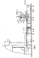
In den Figuren ist der Ausgabebereich der Werksüicke 17, die aus dem Arbeitsbereich 2 der Presse 1 herausgeführt sind, durch einen Antrieb 5 für eine Transfereinrichtung 6 gebildet. Die der Presse entnonmenen Werkstücke gelangen über einen Fertigteilförderer 7, der vermittels eines Motor-Getriebe-Aggregates 21 oder von Stößelantrieb der Presse getrieben wird, zur Auflage auf einen Zuführförderer 8, der aus einer Rollenbahn mit von Motor 22 getriebenen Rollen oder entsprechenden Förderriemen gebildet ist und die Werkstücke bis in den Schwenkbereich der Schwenkeinrichtung 10 transportiert. Die Schwenkeinrichtung besteht im wesentlichen aus einem Gestellrahmen, in dessen oberen Bereich Schwenkarme 11 um einen Drehpunkt herum verschwenkbar bzw. drehbeweglich gelagert sind zum Aufrichten der ankommenden Werkstücke. Der Antrieb der Schwenkarme erfolgt im Uhrzeigersinn in Betrachtersicht über den Antriebsmotor 23, der auf Signal hin angesteuert wird. In der Rollenbahn bzw. bei Verwendung eines Riemenförderers sind Durchtritte freigelassen für die Bewegung der Schwenkarme. Die in die Vertikale verschwenkten Werkstücke werden von Greifelementen 12, beispielsweise von mit gesteuertem Unterdruck arbeitenden Saugelementen, von den Schwenkarmen abgenommen. Die Greifelemente befinden sich hierzu an einen senkrecht zur bisherigen Förderrichtung von einem Motor-Getriebe-Aggregat 24 bewegbaren Laufwagen, der im wesentlichen aus einem Querschieber 16 und ggf. später noch zu beschreibenden Bauelementen gebildet ist und entsprechend seinen unterschiedlichen Aufgaben unterschiedlich ausgeführt sein kann. Der Querschieber ist an einer Traverse 15 verschieblich gelagert, die Teil eines Portals 9 ist, das aus Ständern 13 und Obergurten 14 besteht. Der Querschieber trägt an seinen beiden Endbereichen Saugelemente, wodurch bei Bewegungsstop des Qerschiebers ein Endbereich mit einem Werkstück in einem Ablagebereich befindlich ist, während der andere Endbereich sich im Bereich der Schwenkeinrichtung befindet zum Erfassen eines folgenden Werkstückes. Dieses wird, nachdem es erfaßt ist und das in den Ablagebereich geförderte Werkstück abgelegt ist, als Folge der gegenläufigen Bewegung des Querschiebers in einen zweiten Ablagebereich geführt und hier abgelegt, während ein weiteres Werkstück von den Greifelementen des zunächst erwähnten Endbereiches des Querschiebers erfaßt wird.In the figures, the output area of the
Die Ablagebereiche befinden sich beidseitig und in paralleler Ausrichtung zu der ersten Werkstückförderrichtung und werden gebildet aus jeweils einem Kettenförderer 31, der nicht näher gezeichnete aber bekannte Kettenglieder mit Kettenaufhängern 32 aufweist und über Förder- und Umlenkrollen 33 die erfaßten Werkstücke fördert, z.B. zur ersten Oberflächenbehandlungs-Station oder durch auf eine Rampe 19 und oberhalb dieser laufende Containerförderer 20 aufgesetzte Container 19 in Art von Transportrahmen mit Aufnabmeleisten 26 zur beabstandeten Ablage der Werkstücke. Der schrittweise zu erfolgende Antrieb des Kettenförderers erfolgt über den Motor 34, der schrittweise Antrieb des Containerförderers über das Antriebsaggregat 25.The storage areas are located on both sides and in parallel alignment to the first workpiece conveying direction and are each formed from a
Zur besseren übersicht sind in Fig. 1 die ansonsten vor dem Zuführförderer 8 befindliche Rampe und Container nicht gezeichnet.1 for clarity are not drawn to the front of the otherwise Z
Die Container 18 befinden sich bereits in Höhe des durch die Schwenkeinrichtung 10 in die Vertikale verschwenkten Werkstückes 17. Dieses ist von den Greifelementen 12 des Querschiebers 16 erfaßt für eine Bewegung in Richtung senkrecht zur Zeichnungsebene. Die Fig. 1 läßt die Wölbung der vertikal angeordneten Werkstücke am Querschieber und in dem seitlich offengehaltenen Container erkennen.The
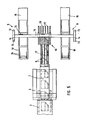
Fig. 2 zeigt u.a. die beidseitig zu den Förderern 7 und 8 sich parallel erstreckenden Ablageeinrichtungen, wie Container 18 und Kettenförderer 31 zur Ablage, zur Aufnahme, zum Einhängen und dgl. Handhabung für die Werkstücke 17. Die Werkstücke sind in der Weise von dem Pressenwerkzeug kommend orientiert, daß sie nach dem Aufrichten mit den Türoberholmen nach oben, also in der Gebrauchslage weitertransportiert werden. Die Position 3 verweist auf Greiferschienen für den Transport der Werkstücke zwischen den Pressenstufen und ggf. zur Ausgabe der Werkstücke. F ig. 2 shows, inter alia, the storage devices extending parallel on both sides to the
Fig. 3 zeigt die vertikale Anordnung von zwei Werkstükken 17, von denen sich eines zur Ablage in dem Container 18, ein weiteres noch in der Verschwenkeinrichtung 10 befindet. Der mit seinen Endbereichen in die Ablagebereiche 18 führbare Querschieber 16 ist an senkrechten Streben 27 und diese an einem Träger 28 befestigt, der an der Traverse 15 und in deren Längsausdehnung motorgetrieben verschieblich ist.Fig. 3 shows the vertical arrangement of two
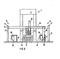
Fig. 4 verweist auf eine in dieser und in den Fig. 5 und 6 dargestellte weitere Ausführungsform mit bodengleichen Containerförderern 20 und zum Einschieben der Werkstücke von oben in die Container höhenverschieblichen Querschieber 16. Die Werkstücke 17 werden in eine Lage oberhalb der Container 18 geschwenkt und quengeführt.Fig. 4 refers to a further embodiment shown in this and in Figs. 5 and 6 with floor-
Nach Fig. 5 werden die Werkstücke 17 in Fahrtrichtung gefördert, wobei sich dieser Ausdruck auf die Einbaulage an Fahrzeug bezieht. Der Einschub der Werkstücke erfolgt von oben in die Container 18. Die in diesen abgelegten Werkstücke lassen die Wölbung und somit ihre Ablagestellung erkennen.5, the
Nach Fig. 6 ist der Querschieber 16 in Längsausdehnung der Traverse 15 motorgetrieben beweglich. Den Endbereichen des Querschiebers sind ein linker und ein rechter Absenkholm 29, 30 zugeordnet, die über das in Fig. 4 gezeigte Antriebsaggregat höhenmäßig verstellbar sind zum Einschieben der Werkstücke in die Container von oben.6, the
Die Greifelemente 12 an dem Querschieber 16 bzw. an den Absenkholmen 29, 30 erfassen die Werkstücke 17 auf der Schwenkeinrichtung 10 von der Seite, so daß beim Ablegen eine Behinderung durch die Greif- und Bewegungselemente nicht erfolgt.The
Fig. 7 zeigt einen von dem Motor 36 drehbaren Wender 35 zur Seitenvertauschung der aufliegenden Werkstücke 17 vor dem Zugriff durch die Verschwenkarme 11.FIG. 7 shows a
Claims (4)
Applications Claiming Priority (2)
| Application Number | Priority Date | Filing Date | Title |
|---|---|---|---|
| DE19823236145 DE3236145A1 (en) | 1982-09-29 | 1982-09-29 | DEVICE FOR DEPOSITING WORKPIECES AFTER THE LAST WORKING STAGE IN A PRESS TOOL |
| DE3236145 | 1982-09-29 |
Publications (3)
| Publication Number | Publication Date |
|---|---|
| EP0104569A2 true EP0104569A2 (en) | 1984-04-04 |
| EP0104569A3 EP0104569A3 (en) | 1984-07-04 |
| EP0104569B1 EP0104569B1 (en) | 1987-07-01 |
Family
ID=6174516
Family Applications (1)
| Application Number | Title | Priority Date | Filing Date |
|---|---|---|---|
| EP83109242A Expired EP0104569B1 (en) | 1982-09-29 | 1983-09-19 | Device for depositing workpieces after the last operation step in a press |
Country Status (2)
| Country | Link |
|---|---|
| EP (1) | EP0104569B1 (en) |
| DE (2) | DE3236145A1 (en) |
Cited By (5)
| Publication number | Priority date | Publication date | Assignee | Title |
|---|---|---|---|---|
| FR2615167A1 (en) * | 1987-05-11 | 1988-11-18 | Peugeot | Installation for storing motor-vehicle components in containers |
| FR2783730A1 (en) * | 1998-09-28 | 2000-03-31 | Mueller Weingarten Maschf | Apparatus for transporting workpieces |
| DE19850964C2 (en) * | 1998-09-28 | 2003-03-27 | Mueller Weingarten Maschf | Device for the transport of workpieces |
| CN104889283A (en) * | 2015-05-17 | 2015-09-09 | 合肥长城制冷科技有限公司 | Orderly fin receiving device for medium-speed punch |
| CN110355288A (en) * | 2019-07-22 | 2019-10-22 | 无锡蓝力智能装备有限公司 | Plate heat exchanger piece numerical control precision form outfit |
Families Citing this family (3)
| Publication number | Priority date | Publication date | Assignee | Title |
|---|---|---|---|---|
| JPS59147728A (en) * | 1983-02-15 | 1984-08-24 | Komatsu Ltd | Automatic palletizing device |
| DE3416277A1 (en) * | 1984-05-03 | 1985-11-07 | Karl 6096 Raunheim Gerlach | DEVICE FOR STACKING THIN-WALLED MOLDED PARTS |
| DE59000969D1 (en) * | 1989-10-18 | 1993-04-08 | Mueller Weingarten Maschf | STORAGE FOR WORKPIECE PARTS IN STEP PRESSES. |
Citations (7)
| Publication number | Priority date | Publication date | Assignee | Title |
|---|---|---|---|---|
| US2392032A (en) * | 1944-02-10 | 1946-01-01 | Caspers Tin Plate Company | Stripping and stacking apparatus and method |
| US2685359A (en) * | 1947-12-03 | 1954-08-03 | United States Steel Corp | Method of handling and assorting sheets |
| US3178041A (en) * | 1961-10-23 | 1965-04-13 | Libbey Owens Ford Glass Co | Sheet handling apparatus |
| DE1756061B1 (en) * | 1968-03-28 | 1970-08-20 | Ziegelei Appbau Gmbh | System for stacking roof tiles bundled into packages in a bundling device |
| DE1943125A1 (en) * | 1969-08-25 | 1971-03-18 | Braas & Co Gmbh | Method and device for erecting and placing flat individual parts, preferably roof tiles, horizontally on a conveyor belt |
| DE2825512B1 (en) * | 1978-06-10 | 1979-10-31 | Lingl Anlagenbau | Device for setting up strand roof tiles in pairs to form rows of rows |
| US4178122A (en) * | 1978-03-29 | 1979-12-11 | Abrahamson Daniel P | Method and apparatus for cubing brick |
-
1982
- 1982-09-29 DE DE19823236145 patent/DE3236145A1/en not_active Withdrawn
-
1983
- 1983-09-19 EP EP83109242A patent/EP0104569B1/en not_active Expired
- 1983-09-19 DE DE8383109242T patent/DE3372258D1/en not_active Expired
Patent Citations (7)
| Publication number | Priority date | Publication date | Assignee | Title |
|---|---|---|---|---|
| US2392032A (en) * | 1944-02-10 | 1946-01-01 | Caspers Tin Plate Company | Stripping and stacking apparatus and method |
| US2685359A (en) * | 1947-12-03 | 1954-08-03 | United States Steel Corp | Method of handling and assorting sheets |
| US3178041A (en) * | 1961-10-23 | 1965-04-13 | Libbey Owens Ford Glass Co | Sheet handling apparatus |
| DE1756061B1 (en) * | 1968-03-28 | 1970-08-20 | Ziegelei Appbau Gmbh | System for stacking roof tiles bundled into packages in a bundling device |
| DE1943125A1 (en) * | 1969-08-25 | 1971-03-18 | Braas & Co Gmbh | Method and device for erecting and placing flat individual parts, preferably roof tiles, horizontally on a conveyor belt |
| US4178122A (en) * | 1978-03-29 | 1979-12-11 | Abrahamson Daniel P | Method and apparatus for cubing brick |
| DE2825512B1 (en) * | 1978-06-10 | 1979-10-31 | Lingl Anlagenbau | Device for setting up strand roof tiles in pairs to form rows of rows |
Cited By (5)
| Publication number | Priority date | Publication date | Assignee | Title |
|---|---|---|---|---|
| FR2615167A1 (en) * | 1987-05-11 | 1988-11-18 | Peugeot | Installation for storing motor-vehicle components in containers |
| FR2783730A1 (en) * | 1998-09-28 | 2000-03-31 | Mueller Weingarten Maschf | Apparatus for transporting workpieces |
| DE19850964C2 (en) * | 1998-09-28 | 2003-03-27 | Mueller Weingarten Maschf | Device for the transport of workpieces |
| CN104889283A (en) * | 2015-05-17 | 2015-09-09 | 合肥长城制冷科技有限公司 | Orderly fin receiving device for medium-speed punch |
| CN110355288A (en) * | 2019-07-22 | 2019-10-22 | 无锡蓝力智能装备有限公司 | Plate heat exchanger piece numerical control precision form outfit |
Also Published As
| Publication number | Publication date |
|---|---|
| EP0104569A3 (en) | 1984-07-04 |
| DE3236145A1 (en) | 1984-03-29 |
| EP0104569B1 (en) | 1987-07-01 |
| DE3372258D1 (en) | 1987-08-06 |
Similar Documents
| Publication | Publication Date | Title |
|---|---|---|
| DE2631942A1 (en) | DEPALLETIZING DEVICE | |
| EP0312498B1 (en) | Conveying method for plates | |
| DE4203118A1 (en) | Transport handling system for stacks of flat objects - has grippers with fingers attached to swivel levers which are attached to holder raised and lowered by piston cylinder unit | |
| EP1323651A2 (en) | Process and apparatus for sorting glass sheets | |
| EP0104569B1 (en) | Device for depositing workpieces after the last operation step in a press | |
| EP0517349B1 (en) | Method and apparatus for charging and discharging platelike products in and from a electrplaiting plant. | |
| DE3107437A1 (en) | DEVICE FOR LOADING A MACHINE TOOL SUPPORT TABLE | |
| DE4213301C2 (en) | Device and method for removing stacked boxes open at the top | |
| DE4205923C2 (en) | Device for stacking bowls or bowl-like objects, in particular dishes bowls | |
| DE3000967A1 (en) | FEEDING AND EMPTYING DEVICE FOR INPUTING AND EXTRACTING A PRESS PACKAGE INTO A OR FROM A PRESS | |
| EP0149146B1 (en) | Method for packing groups of goods in a folding box and a device for executing the method | |
| DE2106091C3 (en) | Device for nested, layer-by-layer stacking of profiled rolling stock | |
| EP0426694B1 (en) | Device for stacking preforms | |
| DE3001010A1 (en) | Loading and unloading system for panel press - has supporting strips and carrier belt synchronised with feed and discharge members | |
| DE3119418C2 (en) | Transfer device when transporting objects for applying coatings | |
| EP0210172B1 (en) | Device for stacking thin-walled parts | |
| EP0256403B1 (en) | Method of transferring champagne bottle wire straps automatically from a machining station to a stacker or from a stacker to a subsequent machining station and device for carrying out the method | |
| DE2435671C3 (en) | Method and device for handling and storing elongated objects | |
| DE102019107077A1 (en) | Conveyor system for moving at least one plate-shaped workpiece | |
| EP1535867B1 (en) | Feed apparatus and method for bales and bundles of tobacco | |
| DE3712838C2 (en) | ||
| DE3151208C2 (en) | Device for removing ferromagnetic sheet metal blanks from sheet metal processing machines | |
| DE8501637U1 (en) | Device for stacking individually arriving objects, e.g. B. workpieces, in superimposed, each containing several objects object layers | |
| DE2727938A1 (en) | Conveyor with roller track and transverse transporter - separates individual workpieces using truck and aligns with roller track | |
| DE2105729C3 (en) | Device for depalletizing a stack with objects arranged in layers on telescopic or dividing shelves |
Legal Events
| Date | Code | Title | Description |
|---|---|---|---|
| PUAI | Public reference made under article 153(3) epc to a published international application that has entered the european phase |
Free format text: ORIGINAL CODE: 0009012 |
|
| AK | Designated contracting states |
Designated state(s): DE FR GB IT SE |
|
| PUAL | Search report despatched |
Free format text: ORIGINAL CODE: 0009013 |
|
| AK | Designated contracting states |
Designated state(s): DE FR GB IT SE |
|
| 17P | Request for examination filed |
Effective date: 19841206 |
|
| 17Q | First examination report despatched |
Effective date: 19860219 |
|
| GRAA | (expected) grant |
Free format text: ORIGINAL CODE: 0009210 |
|
| AK | Designated contracting states |
Kind code of ref document: B1 Designated state(s): DE FR GB IT SE |
|
| ET | Fr: translation filed | ||
| REF | Corresponds to: |
Ref document number: 3372258 Country of ref document: DE Date of ref document: 19870806 |
|
| ITF | It: translation for a ep patent filed |
Owner name: STUDIO JAUMANN |
|
| PLBE | No opposition filed within time limit |
Free format text: ORIGINAL CODE: 0009261 |
|
| STAA | Information on the status of an ep patent application or granted ep patent |
Free format text: STATUS: NO OPPOSITION FILED WITHIN TIME LIMIT |
|
| 26N | No opposition filed | ||
| PG25 | Lapsed in a contracting state [announced via postgrant information from national office to epo] |
Ref country code: GB Effective date: 19880919 |
|
| PG25 | Lapsed in a contracting state [announced via postgrant information from national office to epo] |
Ref country code: SE Effective date: 19880920 |
|
| PG25 | Lapsed in a contracting state [announced via postgrant information from national office to epo] |
Ref country code: FR Free format text: LAPSE BECAUSE OF NON-PAYMENT OF DUE FEES Effective date: 19890531 |
|
| GBPC | Gb: european patent ceased through non-payment of renewal fee | ||
| PG25 | Lapsed in a contracting state [announced via postgrant information from national office to epo] |
Ref country code: DE Effective date: 19890601 |
|
| REG | Reference to a national code |
Ref country code: FR Ref legal event code: ST |
|
| EUG | Se: european patent has lapsed |
Ref document number: 83109242.4 Effective date: 19890712 |