EP0103621B1 - Scrambling and descrambling of television signals for subscription tv - Google Patents
Scrambling and descrambling of television signals for subscription tv Download PDFInfo
- Publication number
- EP0103621B1 EP0103621B1 EP83901125A EP83901125A EP0103621B1 EP 0103621 B1 EP0103621 B1 EP 0103621B1 EP 83901125 A EP83901125 A EP 83901125A EP 83901125 A EP83901125 A EP 83901125A EP 0103621 B1 EP0103621 B1 EP 0103621B1
- Authority
- EP
- European Patent Office
- Prior art keywords
- signals
- tagging
- predetermined
- line
- descrambling
- Prior art date
- Legal status (The legal status is an assumption and is not a legal conclusion. Google has not performed a legal analysis and makes no representation as to the accuracy of the status listed.)
- Expired - Lifetime
Links
Images
Classifications
-
- H—ELECTRICITY
- H04—ELECTRIC COMMUNICATION TECHNIQUE
- H04N—PICTORIAL COMMUNICATION, e.g. TELEVISION
- H04N7/00—Television systems
- H04N7/16—Analogue secrecy systems; Analogue subscription systems
- H04N7/167—Systems rendering the television signal unintelligible and subsequently intelligible
- H04N7/171—Systems operating in the amplitude domain of the television signal
- H04N7/1713—Systems operating in the amplitude domain of the television signal by modifying synchronisation signals
Definitions
- the present invention relates to subscription TV and particularly to methods and apparatus for scrambling and descrambling TV signals so that they may be displayed only at authorized receiving stations.
- the invention is especially suitable for use in scrambling and descrambling systems where sync intervals of the TV signals are suppressed and then reinserted at the appropriate location in the video waveform.
- Features of the invention are applicable for other types of scrambling and wherever a higher level of encoding of scrambling information is desired in order to discourage unauthorized reception of the premium programming.
- additional pulses referred to as tag or tagging pulses are transmitted during a predetermined line interval.
- the additional pulses compound the encoding of the television signal and allow for channel identification to remotely enable or disable the descramblers at the receiving stations where the subscribers are located.
- an additional tag pulse may be transmitted during at least one horizontal interval and repeated during each picture field.
- the tag pulse identifies the channel number of the received signal by virtue of the line number (time slot) associated with the tag pulse.
- One additional tag pulse can identify any one of 262 possibilities, since a field has at least 262 lines (horizontal sweeps between vertical retrace intervals). Transmitting additional tagging pulses on different lines within a field, further compounds the encoding. For example, two pulses on two different lines within a field, provides 34,191 possible codes.
- counting means may be used to count the horizontal line number which is transmitted.
- the timing pulses which control the descrambler may be used to increment a line counter. The occurrence of a tag pulse and the state of the counter when the tag pulse occurs identifies the channel.
- Memory means such as a programmable read only memory (PROM), may be used to verify the receipt of the encoded information and authorize descrambling.
- the state of the counter may be used as the PROM address. The coincidence of an output from the PROM at a predetermined address corresponding to the predetermined line number and a tag pulse received on that line enables the descrambler.
- the descrambler is disabled and the video signal is intermittently disconnected to disrupt it and further distort the display on the TV receiver, if the PROM contents at the address pointed to by the counter is not an authorized line when the tag pulse is received.
- a high level of encoding which discourages unauthorized viewing of premium programming may thereby readily be obtained.
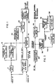
- the scrambler system shown in FIG. 1 is located at the head end of the cable system.
- the baseband video input of the premium programming is converted at the head end of the cable system by an input converter 10 to IF frequency.
- the accompanying audio signal is similarly converted.
- a sync detector 12 detects the horizontal sync pulses.
- a scrambler timing pulse generator 14 generates timing pulses with a delay with respect to the horizontal sync pulses. The timing pulses are applied to a variable attenuator 16 which effectively amplitude modulates the FM carrier of the audio IF signal as by attenuating it except during the timing pulse.
- a scrambler tagging pulse generator 18 also responds to the horizontal sync pulses and outputs a tagging pulse slightly ahead of the timing pulse in a predetermined horizontal line interval.
- the tagging pulse generator may include a counter reset by the vertical sync pulses which counts the horizontal sync pulses. After a count equal to the number of the horizontal line in the picture field which is selected, the tagging pulse is generated.
- This tagging pulse is also applied to the variable attenuator 16 and operates it to remove the attenuation during the tagging pulse. Accordingly, on the predetermined line of the field, the audio IF will have a tagging pulse followed by a timing pulse.
- the tagging pulse generator may generate the tagging pulse by means of a horizontal line counter and PROM arrangement similar to that used in the descrambling system shown in FIG. 3 which is described in detail hereinafter. It will be noted that synchronization is inherent in this system in that the horizontal sync pulses (the horizontal line rate) is used as the basic data rate in transmission of encoding information.
- a scrambler suppression pulse generator 20 generates the suppression pulses coincidentally with the horizontal sync intervals. Since both the suppression and timing pulses derive their timing from the sync pulses in the video signal, the selected time relationship between the timing of the suppression pulses is maintained during each line of the television signal.
- the scrambler suppression pulse generator 20 generates the suppression pulses with sufficient delay to make up the difference in delay in the video audio IF channels.
- Another variable attenuator 22 in the video IF channel suppresses the horizontal sync signal and outputs the scrambled video IF signal to the output combiner and converter 24 of the head end modulator.
- the converter locates the FM audio signal adjacent to the video signal in the RF channel allocated to the premium programming. This RF signal may be applied to the cable at the head end of the cable TV system. Accordingly, the TV signal is scrambled and then encoded with the timing and tagging pulses on the FM audio.
- Each receiving station which is adapted to receive subscription TV is provided with a system which is shown in general in FIG. 2.
- the RF input from the cable goes to the set top converter 26 which converts the cable channels to a standard channel frequency band of the TV receiver which is to display the subscription programming. Other channels may, of course, be selected by the converter 26.
- the TV signal with audio and video combined is, when the premium channel is selected, connected through a variable attenuator 28 to the input terminal (the antenna terminals) of the TV receiver.
- the variable attenuator 28 and other circuits for descrambling may be contained in the set top converter 26.
- the scrambler timing and tag pulses are detected from the FM audio components of the TV signal by a timing and tag pulse detector 30.
- This detector may include the usual traps and filters for the audio component of the TV signal and a diode AM detector.
- the timing pulses are applied to a restore pulse generator 32 which subjects the pulse to a delay corresponding to the delay imposed by the scrambler timing pulse generator 14 with respect to its succeeding horizontal sync pulse.
- the delayed timing pulse is used to time the generation of restoring pulses coincident with the horizontal sync pulses so as to restore and descramble the premium channel output.
- the restore pulse generator 32 is, however, enabled only when the tag pulse is detected in a tagging pulse detector 34. In only the predetermined horizontal line interval will the tag pulse be followed by a timing pulse. The tagging pulse detector 34 will therefore provide an output only during the predetermined horizontal line interval or time slot. This output is applied to an authorization code detector 36 in which the timing pulses are counted. Only when the tagging pulse detector output occurs during the predetermined horizontal line corresponding to the timing pulse count, does the authorization code detector 36 enable the restore pulse generator 32. Unless the predetermined line number is known, the authorization code will not be detected and the scrambled TV signal will proceed out of the RF output of the set top converter to the TV receiver. The authorization code may be changed from time to time to further thwart the unauthorized use of premium programming.
- the method and system of the invention provides for generating of tagging pulses which correspond to at least one predetermined line in each picture field of the TV signal which are scrambled and transmitted with the tagging pulses to the receiving stations.
- the reception of the tagging pulses with their corresponding line are identified and then, and only then, are the TV signals descrambled at the receiving station.
- the premium channel input from the set top converter is fed to a switchable gain amplifier 40 which serves as the variable attenuator.
- This amplifier passes the signal unaltered with a gain of 0 dB during the information portion of each horizontal line.
- the gain of the amplifier 40 is increased by 6 dB. This increase in gain restores the correct level of the signal during the horizontal interval.
- the restoring pulse is provided by the circuitry responsive to the timing pulses which is discussed below.
- the variable attenuator 22 in the scrambler (FIG. 1) attenuates the signal by 6 dB to effectively drop the sync tips below the typical picture level.
- a sound carrier AM demodulator and pulse detector circuit 42 To detect the timing and tagging pulses, there is provided a sound carrier AM demodulator and pulse detector circuit 42.
- the demodulator is tuned to the sound carrier frequency and provides discrimination so as to isolate the video signal spectrum.
- the timing signals modulated on the sound or audio carrier and the tagging signals which precede them on the predetermined horizontal line are detected for use in providing the restore pulse to the switchable gain amplifier and for decoding purposes to determine if descrambling is authorized.
- the output pulses from the demodulator and pulse detector 42 trigger a horizontal sync insertion delay timer 44.
- This timer may be a digital logic circuit with counters to provide the delay time, or a one-shot.
- the timer outputs an 11 microsecond pulse aligned with the horizontal blanking interval.
- This pulse is the restore pulse which will switch the amplifier 40 to the 6 dB gain condition and descramble the TV signal.
- An AND gate 46 controls the application of the restore pulse to the amplifier 40. The restore pulse is applied only if the descrambling system is authorized to descramble the premium channel programming.
- the authorization code detector is provided by much of the remaining circuitry shown in FIG. 3. Unless the authorization code is transmitted by sending the tagging pulse ahead of the timing pulse during the predetermined horizontal line, the AND gate remains inhibited and the switchable gain amplifier 40 is disabled from descrambling the TV signal.
- a two-bit shift register 48 consisting of two D flip-flops 50 and 52 detects the presence of the tagging pulse preceding the timing pulse.
- the first stage 50 of the register 48 toggles to the "high” state when the first pulse is received.
- the second stage 52 of the register 48 toggles "high” only if a second pulse is received in the same horizontal line interval. This is because the shift register is reset by the output of the delay timer 44, shaped in a 1 microsecond one-shot 54 at the end of the horizontal line (i.e., during the horizontal pulse interval when sync tip insertion can occur).
- a 9-bit binary counter 56 counts the current horizontal line since the last vertical retrace (i.e., from the beginning of the picture field).
- a vertical interval retrace detector 58 senses the absence of timing pulses during the vertical retrace interval and causes the counter 56 to reset to "0" just prior to the beginning of a new picture field.
- the counter 56 is toggled and counts the timing and tag pulses which are applied to its count input from the first stage 50 of the register 48.
- the first cell flip-flop 50 provides a sharp transition to assure a proper count.
- the state of the stages of the counter 56 is used as an address code for a programmable read only memory (PROM) 60.
- PROM programmable read only memory
- This memory is programmed with either a "0” or a "1" at each address location between location 1 and location 262.
- the "1” means that a particular channel is authorized to be descrambled, while a "0” means that authorization is not permitted.
- the descrambling is authorized and the authorization code provided by the tagging pulse occurs, if a tag pulse occurs and a "1" is stored at the address pointed to by the horizontal line counter 56. If the tag pulse does not coincide with an authorized address in the PROM 60, the descrambler remains disabled.
- the authorized output from the PROM may, if desired, be applied directly to the AND gate 46.
- the digital integrator 62 uses a 4-bit binary up-down counter 64 which averages the authorization commands over 16 picture fields.
- the integrator has a latch flip-flop 66 which is set only after having received 16 correct commands through the AND gate 68. It will be observed that a reset does not result until at least 16 incorrect commands are received through the other AND gate 70 of the integrator 62. Accordingly, the authorization code will be quickly acquired and then maintains the descrambler in operation.
- the vertical interval reset timer 58 remains in a "high" state.
- the switchable gain amplifier remains in a 0 dB gain state, such that the sync pulses, which have not been suppressed in the unscrambled signal, pass in proper amplitude to the channel output.
- An electronic switch 72, an OR gate 74, and a 6-bit counter 76 further scramble the signal in the absence of the authorization code.
- the vertical interval reset timer 58 toggles the counter 76 so as to provide a square wave pulse train with a 1 second period (1/2 second "high” and 1/2 second “low”).
- This square wave passes through the OR gate 74 and successively causes the switch 72 to open and close for 1/2 second intervals, thereby chopping and further scrambling the TV signal.
- the chopping square wave signal is overridden when an authorization code is detected, since the latch flip-flop 66 goes "high".
- a field rate pulse detector 78 provides a "high” or enable output to override the chopping square wave.
- This detector may be a triggerable flip-flop which has a timer (a one-shot) which causes it to remain “high” if the vertical interval reset timer remains “high” continuously, as is the case when an unscrambled or normal signal is transmitted on the premium channel and there are no timing pulses.
- a timer a one-shot
Description
- The present invention relates to subscription TV and particularly to methods and apparatus for scrambling and descrambling TV signals so that they may be displayed only at authorized receiving stations.
- The invention is especially suitable for use in scrambling and descrambling systems where sync intervals of the TV signals are suppressed and then reinserted at the appropriate location in the video waveform. Features of the invention are applicable for other types of scrambling and wherever a higher level of encoding of scrambling information is desired in order to discourage unauthorized reception of the premium programming.
- While various schemes have been suggested to compound the encoding system used to protect subscription TV programming from unauthorized reception, the problem remains to provide a high level of encoding with minimum hardware complexity. Complex hardware is involved in systems which send the multibit coded data words modulated on the sound carrier during the vertical retrace interval of the TV signal. The coded data contains the channel number and information to authorize a particular set of descramblers to work. Such a scheme is disclosed in U.S. Patent US-A-3,919,462 issued November 11, 1975. Another scheme uses a separate carrier which is located outside of the band of the TV signal. This carrier is modulated with a multibit pattern, for example tones, containing information identifying the authorized channels (see U.S. Patent US-A-3,184,537, issued May 18, 1965). The transmission of the multibit codes requires precision telemetry for the transmission of the code words. Complex encoders and decoders are also needed. The scheme where the codes are transmitted on out-of-band carrier even requires a separate receiver tuned to that carrier. The hardware complexity and consequent cost of high level encoding has caused it not to be adopted, notwithstanding that high level coding is desirable to discourage and prevent unauthorized reception of the premium subscription TV programs.
- It is also desirable to provide for high level encoding of premium programming which is compatible with the sync suppressed scrambling and descrambling systems which are used extensively for premium programming. Such a system is described in U.S. Patent Application Serial No. 334,040 filed December 23, 1981 (US-A-4 466 017 Published 14.8.1984) in the name of Robert O. Banker and assigned to the same assignee as this application. In such sync suppressed systems, amplitude modulated, band-limited timing pulses are transmitted on the audio or sound carrier. These timing pulses are synchronous with the horizontal sync intervals and are used to time the reinsertion of the suppressed horizontal sync at the appropriate location on the video signal which accompanies the audio.
- Briefly, in a system in accordance with the invention additional pulses, referred to as tag or tagging pulses are transmitted during a predetermined line interval. The additional pulses compound the encoding of the television signal and allow for channel identification to remotely enable or disable the descramblers at the receiving stations where the subscribers are located.
- In accordance with the invention, an additional tag pulse may be transmitted during at least one horizontal interval and repeated during each picture field. The tag pulse identifies the channel number of the received signal by virtue of the line number (time slot) associated with the tag pulse. One additional tag pulse can identify any one of 262 possibilities, since a field has at least 262 lines (horizontal sweeps between vertical retrace intervals). Transmitting additional tagging pulses on different lines within a field, further compounds the encoding. For example, two pulses on two different lines within a field, provides 34,191 possible codes.
- In implementing the invention, counting means may be used to count the horizontal line number which is transmitted. In a suppressed sync system, the timing pulses which control the descrambler may be used to increment a line counter. The occurrence of a tag pulse and the state of the counter when the tag pulse occurs identifies the channel. Memory means, such as a programmable read only memory (PROM), may be used to verify the receipt of the encoded information and authorize descrambling. The state of the counter may be used as the PROM address. The coincidence of an output from the PROM at a predetermined address corresponding to the predetermined line number and a tag pulse received on that line enables the descrambler. The descrambler is disabled and the video signal is intermittently disconnected to disrupt it and further distort the display on the TV receiver, if the PROM contents at the address pointed to by the counter is not an authorized line when the tag pulse is received. A high level of encoding which discourages unauthorized viewing of premium programming may thereby readily be obtained.
- Accordingly, it is an object of the present invention to provide improved methods and apparatus for the scrambling and descrambling of television signals.
- It is another object of the invention to provide an improved system and method for obtaining high level encoding of television signals with a minimum of hardware complexity.
- It is a further object of the present invention to provide an improved system and method for scrambling and descrambling of TV signals which does not require the transmission of a complex code word.
- It is a still further object of the present invention to provide an improved system and method for the transmission of sync suppressed TV signals which enables them to be encoded with a high degree of coding efficiency and with minimum hardware complexity.
- In Accordance with the present invention the following is provided
- a) a method of scrambling and descrambling TV signals as claimed in claim 1;
- b) a method of descrambling TV signals as claimed in claim 7;
- c) a system for scrambling and descrambling TV signals as claimed in
claim 12; and - d) a system for descrambling TV signals as claimed in
claim 18. - Preferred embodiments of the invention are disclosed in the dependent claims.
- The foregoing and other objects, features and advantages of the invention as well as the best mode now known for practicing the invention and the presently preferred embodiment thereof will become more apparent from a reading of the following description in connection with the accompanying drawings in which:
- FIG. 1 is a block diagram illustrating, in a general manner, a system for sync suppression scrambling in accordance with the invention;
- FIG. 2 is a block diagram illustrating, in a general manner, a system for sync suppression descrambling in accordance with the invention;
- FIG. 3 is a more detailed block diagram illustrating a descrambling system embodying the invention.
- The scrambler system shown in FIG. 1 is located at the head end of the cable system. The baseband video input of the premium programming is converted at the head end of the cable system by an
input converter 10 to IF frequency. The accompanying audio signal is similarly converted. Async detector 12 detects the horizontal sync pulses. A scrambler timing pulse generator 14 generates timing pulses with a delay with respect to the horizontal sync pulses. The timing pulses are applied to avariable attenuator 16 which effectively amplitude modulates the FM carrier of the audio IF signal as by attenuating it except during the timing pulse. - A scrambler
tagging pulse generator 18 also responds to the horizontal sync pulses and outputs a tagging pulse slightly ahead of the timing pulse in a predetermined horizontal line interval. The tagging pulse generator may include a counter reset by the vertical sync pulses which counts the horizontal sync pulses. After a count equal to the number of the horizontal line in the picture field which is selected, the tagging pulse is generated. This tagging pulse is also applied to thevariable attenuator 16 and operates it to remove the attenuation during the tagging pulse. Accordingly, on the predetermined line of the field, the audio IF will have a tagging pulse followed by a timing pulse. The tagging pulse generator may generate the tagging pulse by means of a horizontal line counter and PROM arrangement similar to that used in the descrambling system shown in FIG. 3 which is described in detail hereinafter. It will be noted that synchronization is inherent in this system in that the horizontal sync pulses (the horizontal line rate) is used as the basic data rate in transmission of encoding information. - A scrambler
suppression pulse generator 20 generates the suppression pulses coincidentally with the horizontal sync intervals. Since both the suppression and timing pulses derive their timing from the sync pulses in the video signal, the selected time relationship between the timing of the suppression pulses is maintained during each line of the television signal. The scramblersuppression pulse generator 20 generates the suppression pulses with sufficient delay to make up the difference in delay in the video audio IF channels. Anothervariable attenuator 22 in the video IF channel suppresses the horizontal sync signal and outputs the scrambled video IF signal to the output combiner and converter 24 of the head end modulator. The converter locates the FM audio signal adjacent to the video signal in the RF channel allocated to the premium programming. This RF signal may be applied to the cable at the head end of the cable TV system. Accordingly, the TV signal is scrambled and then encoded with the timing and tagging pulses on the FM audio. - Each receiving station which is adapted to receive subscription TV is provided with a system which is shown in general in FIG. 2. The RF input from the cable goes to the
set top converter 26 which converts the cable channels to a standard channel frequency band of the TV receiver which is to display the subscription programming. Other channels may, of course, be selected by theconverter 26. The TV signal with audio and video combined is, when the premium channel is selected, connected through avariable attenuator 28 to the input terminal (the antenna terminals) of the TV receiver. Thevariable attenuator 28 and other circuits for descrambling may be contained in theset top converter 26. The scrambler timing and tag pulses are detected from the FM audio components of the TV signal by a timing andtag pulse detector 30. This detector may include the usual traps and filters for the audio component of the TV signal and a diode AM detector. The timing pulses are applied to a restorepulse generator 32 which subjects the pulse to a delay corresponding to the delay imposed by the scrambler timing pulse generator 14 with respect to its succeeding horizontal sync pulse. The delayed timing pulse is used to time the generation of restoring pulses coincident with the horizontal sync pulses so as to restore and descramble the premium channel output. - The restore
pulse generator 32 is, however, enabled only when the tag pulse is detected in a taggingpulse detector 34. In only the predetermined horizontal line interval will the tag pulse be followed by a timing pulse. The taggingpulse detector 34 will therefore provide an output only during the predetermined horizontal line interval or time slot. This output is applied to anauthorization code detector 36 in which the timing pulses are counted. Only when the tagging pulse detector output occurs during the predetermined horizontal line corresponding to the timing pulse count, does theauthorization code detector 36 enable the restorepulse generator 32. Unless the predetermined line number is known, the authorization code will not be detected and the scrambled TV signal will proceed out of the RF output of the set top converter to the TV receiver. The authorization code may be changed from time to time to further thwart the unauthorized use of premium programming. - It will therefore be seen that the method and system of the invention provides for generating of tagging pulses which correspond to at least one predetermined line in each picture field of the TV signal which are scrambled and transmitted with the tagging pulses to the receiving stations. At the receiving stations the reception of the tagging pulses with their corresponding line are identified and then, and only then, are the TV signals descrambled at the receiving station.
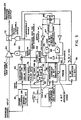
- Referring next to FIG. 3 the premium channel input from the set top converter is fed to a
switchable gain amplifier 40 which serves as the variable attenuator. This amplifier passes the signal unaltered with a gain of 0 dB during the information portion of each horizontal line. During the horizontal retrace where the horizontal sync pulse (blanking plus sync tip) occurs, the gain of theamplifier 40 is increased by 6 dB. This increase in gain restores the correct level of the signal during the horizontal interval. The restoring pulse is provided by the circuitry responsive to the timing pulses which is discussed below. Thevariable attenuator 22 in the scrambler (FIG. 1) attenuates the signal by 6 dB to effectively drop the sync tips below the typical picture level. Therefore, increasing the gain by a corresponding 6 dB restores the correct sync to picture level. To detect the timing and tagging pulses, there is provided a sound carrier AM demodulator andpulse detector circuit 42. The demodulator is tuned to the sound carrier frequency and provides discrimination so as to isolate the video signal spectrum. The timing signals modulated on the sound or audio carrier and the tagging signals which precede them on the predetermined horizontal line are detected for use in providing the restore pulse to the switchable gain amplifier and for decoding purposes to determine if descrambling is authorized. - The output pulses from the demodulator and
pulse detector 42 trigger a horizontal syncinsertion delay timer 44. This timer may be a digital logic circuit with counters to provide the delay time, or a one-shot. The timer outputs an 11 microsecond pulse aligned with the horizontal blanking interval. This pulse is the restore pulse which will switch theamplifier 40 to the 6 dB gain condition and descramble the TV signal. An ANDgate 46 controls the application of the restore pulse to theamplifier 40. The restore pulse is applied only if the descrambling system is authorized to descramble the premium channel programming. - The authorization code detector is provided by much of the remaining circuitry shown in FIG. 3. Unless the authorization code is transmitted by sending the tagging pulse ahead of the timing pulse during the predetermined horizontal line, the AND gate remains inhibited and the
switchable gain amplifier 40 is disabled from descrambling the TV signal. - A two-
bit shift register 48 consisting of two D flip-flops first stage 50 of theregister 48 toggles to the "high" state when the first pulse is received. Thesecond stage 52 of theregister 48 toggles "high" only if a second pulse is received in the same horizontal line interval. This is because the shift register is reset by the output of thedelay timer 44, shaped in a 1 microsecond one-shot 54 at the end of the horizontal line (i.e., during the horizontal pulse interval when sync tip insertion can occur). - A 9-bit
binary counter 56 counts the current horizontal line since the last vertical retrace (i.e., from the beginning of the picture field). A vertical interval retracedetector 58 senses the absence of timing pulses during the vertical retrace interval and causes thecounter 56 to reset to "0" just prior to the beginning of a new picture field. Thecounter 56 is toggled and counts the timing and tag pulses which are applied to its count input from thefirst stage 50 of theregister 48. The first cell flip-flop 50 provides a sharp transition to assure a proper count. - The state of the stages of the
counter 56 is used as an address code for a programmable read only memory (PROM) 60. This memory is programmed with either a "0" or a "1" at each address location between location 1 and location 262. The "1" means that a particular channel is authorized to be descrambled, while a "0" means that authorization is not permitted. - The descrambling is authorized and the authorization code provided by the tagging pulse occurs, if a tag pulse occurs and a "1" is stored at the address pointed to by the
horizontal line counter 56. If the tag pulse does not coincide with an authorized address in thePROM 60, the descrambler remains disabled. The authorized output from the PROM may, if desired, be applied directly to the ANDgate 46. - It is desirable, however, to use a digital integrator 62 for noise immunity thereby obviating to a great extent the possibility of either missing a tagging pulse or adding an extraneous tagging pulse due to operation in a noisy signal environment. The digital integrator 62 uses a 4-bit binary up-
down counter 64 which averages the authorization commands over 16 picture fields. The integrator has a latch flip-flop 66 which is set only after having received 16 correct commands through the ANDgate 68. It will be observed that a reset does not result until at least 16 incorrect commands are received through the other ANDgate 70 of the integrator 62. Accordingly, the authorization code will be quickly acquired and then maintains the descrambler in operation. In the event that the TV signal is not scrambled and timing pulses are absent, the vertical interval resettimer 58 remains in a "high" state. The switchable gain amplifier remains in a 0 dB gain state, such that the sync pulses, which have not been suppressed in the unscrambled signal, pass in proper amplitude to the channel output. - An
electronic switch 72, an OR gate 74, and a 6-bit counter 76 further scramble the signal in the absence of the authorization code. The vertical interval resettimer 58 toggles thecounter 76 so as to provide a square wave pulse train with a 1 second period (1/2 second "high" and 1/2 second "low"). This square wave passes through the OR gate 74 and successively causes theswitch 72 to open and close for 1/2 second intervals, thereby chopping and further scrambling the TV signal. The chopping square wave signal is overridden when an authorization code is detected, since the latch flip-flop 66 goes "high". A fieldrate pulse detector 78 provides a "high" or enable output to override the chopping square wave. This detector may be a triggerable flip-flop which has a timer (a one-shot) which causes it to remain "high" if the vertical interval reset timer remains "high" continuously, as is the case when an unscrambled or normal signal is transmitted on the premium channel and there are no timing pulses.
Claims (22)
- The method of scrambling and descrambling TV signals which comprises the steps of generating at least one tagging pulse which corresponds uniquely to at least one predetermined horizontal line of the lines in each picture field of the TV signals by occuring coincidentally with said predetermined horizontal line, scrambling said TV signals, transmitting said scrambled signals with said tagging pulse to receiving stations, storing information identifying such predetermined horizontal line at a receiving station, identifying in response to the stored information the reception of said tagging pulse in coincidence with said predetermined horizontal line at a receiving station, and descrambling said TV signals at said receiving station when the reception of said tagging pulse and said predetermined line in coincidence with each other is identified.
- The method according to claim 1 wherein said identifying step includes the step of counting said lines as they occur during said fields, and detecting the occurence of each of said tagging pulse and the counting of a predetermined number of said lines.
- The method according to claim 1 or 2 wherein said generating step comprises generating said tagging pulse in synchronism with said predetermined line.
- The method according to any of claims 1-3 further comprising generating timing pulses in synchronism with each of the horizontal lines of said picture field and generating said tagging pulse during the interval of said predetermined horizontal line, and said counting step is carried out by counting said timing pulses to detect the occurence of said predetermined line.
- The method according to any of claim 2-4 wherein said scrambling step is carried out by suppressing the horizontal sync pulses of said TV signal in predetermined time relationship with said timing pulses, and said descrambling step is carried out by restoring the amplitude of said horizontal sync pulses in predetermined time relationship with said timing pulses when the counting of a predetermined number of said timing pulses (which indicates the occurence of said predetermined line) and the reception of a tagging pulse occurs during the interval of said predetermined horizontal line.
- The method according to any of claims 1-5 wherein said transmitting step comprises the step of modulating the audio signals of said TV signals with said timing and tagging pulses to encode said TV signals, and demodulating said audio signals at said receiving station to derive said timing and tagging pulses.
- The method of descrambling TV signals which have been encoded with tagging signals which occur uniquely during the interval of at least one predetermined line of the lines in each field of said TV signals, which method comprises the step of detecting said tagging signals, storing information identifying said predetermined line, detecting the occurence of said predetermined line in response to said stored information, identifying the simultaneous detection of said tagging signals and said predetermined line, and enabling the descrambling of said TV signals when said tagging signals are identified as simultaneously occuring with said predetermine line.
- The method according to claim 7 wherein said TV signals are also encoded with scrambling control signals, further comprising detecting said control signals, and inhibiting said control signals to prevent descrambling of said signals in the absence of the identification of said tagging signals as occuring simultaneously with said predetermined line.
- The method according to claim 8 wherein said step of detecting the occurence of said predetermined line comprises the steps of counting said lines, and said identifying step comprises detecting the occurence of said tagging signal when no less and no more than a predetermined number of lines is counted, which number corresponds to said predetermined line.
- The method according to claim 9 wherein said control signals are timing signals which control the descrambling of the TV signals and occur in predetermined time relationship with the horizontal sync pulses of said TV signals and are encoded with said tagging signals, said counting step is carried out by counting said timing signals to count said lines, and said enabling step is carried out to enable the descrambling of said TV signals in response to said timing signals when said tagging signals occur coincident with the occurence of a count equal to said predetermined number.
- The method according to claim 7-10 further comprising chopping said TV signal to further scramble said TV signal in the absence of identification of said tagging signals as occuring simultaneously with said predetermined line.
- The system for scrambling and descrambling TV signals which comprises means for generating at least one tagging pulse which corresponds uniquely to at least one predetermined line of the horizontal lines in each picture field of the TV signals by occuring coincidentally only with said predetermined line, means for scrambling said TV signals, means for transmitting said scrambled signals with said tagging pulse to receiving stations, means for storing information identifying said predetermined line, means responsive to said stored information for identifying the reception of said tagging pulse in coincidence with said predetermined line at a receiving station, and means for descrambling said TV signals at said receiving station when the reception of said tagging pulse and said predetermined line in coincidence with each other is identified.
- The system according to claim 12 wherein said identifying means includes means for counting said lines as they occur during said field, and means for detecting the occurence of said tagging pulse upon a count corresponding no less and no more than to said predetermined line.
- The system according to claim 12 or 13 wherein said generating means comprises means for generating said tagging pulse in synchronism with said predetermined line.
- The system according to any of claims 12-14 further comprising means for generating timing pulses in synchronism with each of said lines of said field and for generating said tagging pulse during the interval of said predetermined horizontal line, and said counting means is operable for counting said timing pulses to detect the occurrence of said predetermined line.
- The system according to any of claims 13-15 wherein said scrambling means comprises means for suppressing the horizontal sync pulses of said TV signal in predetermined time relationship with said timing pulses, and said descrambling means comprises means for restoring the amplitude of said horizontal sync pulses in predetermined time relationship with said timing pulses when the counting of a predetermined number of said timing pulses (which indicates the occurence of said predetermined horizontal line) and the reception of a tagging pulse occurs during the interval of said predetermined horizontal line.
- The system according to any of claims 12-16 wherein said transmitting means comprises means for modulating the audio signals of said TV signals with said timing and tagging pulses to encode said TV signals, and means for demodulating said audio signals at said receiving station to derive said timing and tagging pulses.
- The system for descrambling TV signals which have been encoded with tagging pulses which occur uniquely during the interval of at least one predetermined horizontal line in each field of said TV signals, which system comprises means for detecting said tagging signals, means for storing information identifying said predetermined horizontal line, means responsive to said storing means for detecting the occurence of said predetermined horizontal line, means for identifying the simultaneous detection of said tagging signals and said predetermined line, and means for enabling the descrambling of said TV signals when said tagging signals are identified as simultaneously occuring with said predetermined line.
- The system according to claim 18 wherein said TV signals are also encoded with scrambling control signals, further comprising means for detecting said control signals and inhibiting said control signals to prevent descrambling of said signals in the absence of the identification of said tagging signals as occuring simultaneously with said predetermined line.
- The system according to claim 19 wherein said identifying means comprises means for counting said lines, and means for detecting the occurence of said tagging signal when no less and no more than a predetermined number of lines is counted, which corresponds to said predetermined line.
- The system according to claim 20 wherein said control signals are timing signals which control the descrambling of the TV signals and occur in predetermined time relationship with the horizontal sync pulses of said TV signals and are encoded with said tagging signals, said counting means comprising means for counting said timing signals to count said lines, and said enabling means being operable to enable the descrambling of said TV signals in response to said timing signals when said tagging signals occur coincident with the occurence of a count equal to said predetermined number.
- The system according to claim 18-21 further comprising means for chopping said TV signal to further scramble said TV signal in the absence of identification of said tagging signals as occuring simultaneously with said predetermined line.
Priority Applications (1)
| Application Number | Priority Date | Filing Date | Title |
|---|---|---|---|
| AT83901125T ATE69344T1 (en) | 1982-03-15 | 1983-02-14 | ENCRYPTION AND DECRYPTION OF TELEVISION SIGNALS FOR SUBSCRIPTION TELEVISION. |
Applications Claiming Priority (2)
| Application Number | Priority Date | Filing Date | Title |
|---|---|---|---|
| US06/358,135 US4471380A (en) | 1982-03-15 | 1982-03-15 | Scrambling and descrambling of television signals for subscription TV |
| US358135 | 1982-03-15 |
Publications (3)
| Publication Number | Publication Date |
|---|---|
| EP0103621A1 EP0103621A1 (en) | 1984-03-28 |
| EP0103621A4 EP0103621A4 (en) | 1986-05-16 |
| EP0103621B1 true EP0103621B1 (en) | 1991-11-06 |
Family
ID=23408443
Family Applications (1)
| Application Number | Title | Priority Date | Filing Date |
|---|---|---|---|
| EP83901125A Expired - Lifetime EP0103621B1 (en) | 1982-03-15 | 1983-02-14 | Scrambling and descrambling of television signals for subscription tv |
Country Status (7)
| Country | Link |
|---|---|
| US (1) | US4471380A (en) |
| EP (1) | EP0103621B1 (en) |
| JP (1) | JPH0744682B2 (en) |
| AU (1) | AU566603B2 (en) |
| CA (1) | CA1186793A (en) |
| DE (1) | DE3382450D1 (en) |
| WO (1) | WO1983003329A1 (en) |
Families Citing this family (47)
| Publication number | Priority date | Publication date | Assignee | Title |
|---|---|---|---|---|
| US4802214A (en) * | 1982-04-23 | 1989-01-31 | Eagle Comtronics, Inc. | Method and apparatus for identifying and rendering operative particular descramblers in a television signal scrambling system |
| JPS595790A (en) * | 1982-07-01 | 1984-01-12 | Pioneer Electronic Corp | Scrambling method of television video |
| US4523228A (en) * | 1983-02-15 | 1985-06-11 | Scientific Atlanta Inc. | Sync suppression scrambling of television signals for subscription TV |
| US4605961A (en) * | 1983-12-22 | 1986-08-12 | Frederiksen Jeffrey E | Video transmission system using time-warp scrambling |
| US4712237A (en) * | 1984-10-29 | 1987-12-08 | Zenith Electronics Corporation | Method and apparatus for unscrambling sync-suppressed television signals |
| US4603349A (en) * | 1984-12-04 | 1986-07-29 | General Instrument Corporation | Cable television system with stereo sound reproduction |
| CA1284211C (en) * | 1985-04-29 | 1991-05-14 | Terrence Henry Pocock | Cable television system selectively distributing pre-recorder video and audio messages |
| US4817142A (en) * | 1985-05-21 | 1989-03-28 | Scientific Atlanta, Inc. | Restoring framing in a communications system |
| US4716588A (en) * | 1985-10-29 | 1987-12-29 | Payview Limited | Addressable subscription television system having multiple scrambling modes |
| JPS6277980U (en) * | 1985-11-05 | 1987-05-19 | ||
| US4688247A (en) * | 1986-06-05 | 1987-08-18 | Oak Industries Inc. | Pay TV scrambling by audio encryption |
| US5142575A (en) * | 1988-04-29 | 1992-08-25 | Scientific-Atlanta, Inc. | Method and apparatus for improving video scrambling and employing split sync pulses |
| US4924498A (en) * | 1988-04-29 | 1990-05-08 | Scientific Atlanta, Inc. | Method and apparatus for improving video scrambling and employing split snyc pulses |
| US4922532A (en) * | 1988-07-29 | 1990-05-01 | Scientific-Atlanta, Inc. | Sync suppression scrambling and descrambling of television signals for subscription TV |
| US5177787A (en) * | 1989-05-01 | 1993-01-05 | Scientific-Atlanta, Inc | Scrambler with self-calibration |
| DK0483234T3 (en) * | 1989-07-20 | 1995-04-24 | Scientific Atlanta | Subcarrier Multiplication Method, which retains AM information in FM systems |
| US5883661A (en) * | 1990-09-28 | 1999-03-16 | Ictv, Inc. | Output switching for load levelling across multiple service areas |
| US5587734A (en) * | 1990-09-28 | 1996-12-24 | Ictv, Inc. | User interface for selecting television information services through pseudo-channel access |
| US5412720A (en) * | 1990-09-28 | 1995-05-02 | Ictv, Inc. | Interactive home information system |
| US5557316A (en) * | 1990-09-28 | 1996-09-17 | Ictv, Inc. | System for distributing broadcast television services identically on a first bandwidth portion of a plurality of express trunks and interactive services over a second bandwidth portion of each express trunk on a subscriber demand basis |
| US5594507A (en) * | 1990-09-28 | 1997-01-14 | Ictv, Inc. | Compressed digital overlay controller and method for MPEG type video signal |
| US5526034A (en) * | 1990-09-28 | 1996-06-11 | Ictv, Inc. | Interactive home information system with signal assignment |
| US5442700A (en) * | 1990-09-28 | 1995-08-15 | Ictv, Inc. | Scrambling method |
| ATE147917T1 (en) * | 1991-04-12 | 1997-02-15 | Thomson Multimedia Sa | METHOD FOR CONTROLLING A RECORDING DEVICE |
| US5319709A (en) * | 1991-06-13 | 1994-06-07 | Scientific-Atlanta, Inc. | System for broadband descrambling of sync suppressed television signals |
| US5309514A (en) * | 1992-06-01 | 1994-05-03 | Scientific-Atlanta, Inc. | Pulse generator including a memory for storing pulses for modulation on a carrier of a television signal |
| JPH11507795A (en) * | 1995-06-08 | 1999-07-06 | アイシーティーブイ・インク | Switch channel system |
| DE69622233T2 (en) * | 1995-09-05 | 2003-03-27 | Hitachi Ltd | Digital access control procedures |
| US5870472A (en) * | 1996-11-12 | 1999-02-09 | General Instrument Corporation | Dynamic relocation of the service data channel |
| US6307593B1 (en) * | 1997-10-03 | 2001-10-23 | Wavetek Corporation | Pulsed leakage tagging signal |
| EP1038401A1 (en) * | 1997-12-09 | 2000-09-27 | ICTV,Inc. | Virtual lan printing over interactive cable television system |
| US6424716B1 (en) * | 1998-12-15 | 2002-07-23 | Macrovision Corp. | Method and apparatus for improved horizontal and vertical overlay signals for greater concealment in modern TV sets |
| US6519773B1 (en) | 2000-02-08 | 2003-02-11 | Sherjil Ahmed | Method and apparatus for a digitized CATV network for bundled services |
| US8074248B2 (en) | 2005-07-26 | 2011-12-06 | Activevideo Networks, Inc. | System and method for providing video content associated with a source image to a television in a communication network |
| US9826197B2 (en) | 2007-01-12 | 2017-11-21 | Activevideo Networks, Inc. | Providing television broadcasts over a managed network and interactive content over an unmanaged network to a client device |
| WO2008088741A2 (en) | 2007-01-12 | 2008-07-24 | Ictv, Inc. | Interactive encoded content system including object models for viewing on a remote device |
| US7660570B2 (en) * | 2007-03-12 | 2010-02-09 | John Mezzalingua Associates, Inc. | Active step attenuator |
| CA2814070A1 (en) | 2010-10-14 | 2012-04-19 | Activevideo Networks, Inc. | Streaming digital video between video devices using a cable television system |
| EP2695388B1 (en) | 2011-04-07 | 2017-06-07 | ActiveVideo Networks, Inc. | Reduction of latency in video distribution networks using adaptive bit rates |
| WO2013106390A1 (en) | 2012-01-09 | 2013-07-18 | Activevideo Networks, Inc. | Rendering of an interactive lean-backward user interface on a television |
| US9800945B2 (en) | 2012-04-03 | 2017-10-24 | Activevideo Networks, Inc. | Class-based intelligent multiplexing over unmanaged networks |
| US9123084B2 (en) | 2012-04-12 | 2015-09-01 | Activevideo Networks, Inc. | Graphical application integration with MPEG objects |
| WO2014145921A1 (en) | 2013-03-15 | 2014-09-18 | Activevideo Networks, Inc. | A multiple-mode system and method for providing user selectable video content |
| US9326047B2 (en) | 2013-06-06 | 2016-04-26 | Activevideo Networks, Inc. | Overlay rendering of user interface onto source video |
| US9219922B2 (en) | 2013-06-06 | 2015-12-22 | Activevideo Networks, Inc. | System and method for exploiting scene graph information in construction of an encoded video sequence |
| US9294785B2 (en) | 2013-06-06 | 2016-03-22 | Activevideo Networks, Inc. | System and method for exploiting scene graph information in construction of an encoded video sequence |
| US9788029B2 (en) | 2014-04-25 | 2017-10-10 | Activevideo Networks, Inc. | Intelligent multiplexing using class-based, multi-dimensioned decision logic for managed networks |
Family Cites Families (12)
| Publication number | Priority date | Publication date | Assignee | Title |
|---|---|---|---|---|
| US2862048A (en) * | 1953-08-17 | 1958-11-25 | Zenith Radio Corp | Subscription television system |
| US2889399A (en) * | 1954-12-31 | 1959-06-02 | Jr John Hays Hammond | Single frame facsimile system |
| US3184537A (en) * | 1960-10-04 | 1965-05-18 | Paramount Pictures Corp | Subscription-television system employing suppression of synchronizing signals |
| US3530232A (en) * | 1966-06-17 | 1970-09-22 | Intern Telemeter Corp | Subscription television system |
| US3777053A (en) * | 1972-05-16 | 1973-12-04 | Optical Systems Corp | Converter for catv |
| US3919462A (en) * | 1973-08-15 | 1975-11-11 | System Dev Corp | Method and apparatus for scrambling and unscrambling communication signals |
| US4024574A (en) * | 1975-02-26 | 1977-05-17 | Teleglobe Pay Tv System Inc. | Validation method and apparatus for pay television systems |
| US4068264A (en) * | 1976-07-19 | 1978-01-10 | Teleglobe Pay-Tv System, Inc. | Pay television system utilizing binary coding |
| US4115807A (en) * | 1976-07-19 | 1978-09-19 | Pires H George | Telephone billing apparatus for a subscription television system |
| US4095258A (en) * | 1976-10-15 | 1978-06-13 | Blonder-Tongue Laboratories, Inc. | Apparatus for decoding scrambled television and similar transmissions |
| US4215366A (en) * | 1977-10-19 | 1980-07-29 | Feature Film Services | Subscriber-limited reception television broadcast security encoder-decoder system |
| US4338628A (en) * | 1979-12-19 | 1982-07-06 | Dynacom International, Inc. | Scrambled video communication system |
-
1982
- 1982-03-15 US US06/358,135 patent/US4471380A/en not_active Expired - Lifetime
-
1983
- 1983-02-14 AU AU13775/83A patent/AU566603B2/en not_active Ceased
- 1983-02-14 EP EP83901125A patent/EP0103621B1/en not_active Expired - Lifetime
- 1983-02-14 JP JP58501154A patent/JPH0744682B2/en not_active Expired - Lifetime
- 1983-02-14 DE DE8383901125T patent/DE3382450D1/en not_active Expired - Fee Related
- 1983-02-14 WO PCT/US1983/000187 patent/WO1983003329A1/en active IP Right Grant
- 1983-03-14 CA CA000423499A patent/CA1186793A/en not_active Expired
Also Published As
| Publication number | Publication date |
|---|---|
| DE3382450D1 (en) | 1991-12-12 |
| AU566603B2 (en) | 1987-10-22 |
| EP0103621A1 (en) | 1984-03-28 |
| JPH0744682B2 (en) | 1995-05-15 |
| CA1186793A (en) | 1985-05-07 |
| AU1377583A (en) | 1983-10-24 |
| US4471380A (en) | 1984-09-11 |
| EP0103621A4 (en) | 1986-05-16 |
| WO1983003329A1 (en) | 1983-09-29 |
| JPS59500545A (en) | 1984-03-29 |
Similar Documents
| Publication | Publication Date | Title |
|---|---|---|
| EP0103621B1 (en) | Scrambling and descrambling of television signals for subscription tv | |
| US4523228A (en) | Sync suppression scrambling of television signals for subscription TV | |
| EP0096724B1 (en) | Sync suppression scrambling of television signals for subscription tv | |
| US4864614A (en) | Authorising coded signals | |
| EP0128771B1 (en) | Timing generator for sync suppressed television signals | |
| EP0060299B1 (en) | Multiple signal transmission method and system, particularly for television | |
| EP0053885B1 (en) | Protected television signal distribution system | |
| US4410911A (en) | Multiple signal transmission method and system, particularly for television | |
| US4562465A (en) | Adaptive video descrambling system | |
| US5230019A (en) | Key signal conversion device for CATV system | |
| US6292567B1 (en) | Sync suppression television security system with addressable sync restoration | |
| FI85206B (en) | AOTERSTAELLANDE AV RAMLAOSNINGEN I TELEKOMMUNIKATIONSSYSTEM. | |
| US4614970A (en) | Descrambler apparatus | |
| US5651065A (en) | Insertion of supplemental burst into video signals to thwart piracy and/or carry data | |
| US5161187A (en) | Cable television system | |
| US4636852A (en) | Scrambling and descrambling of television signals for subscription TV | |
| US4542407A (en) | Method and apparatus for scrambling and descrambling television programs | |
| US5161188A (en) | Scrambling video by horizontal and vertical time shifting | |
| US4802214A (en) | Method and apparatus for identifying and rendering operative particular descramblers in a television signal scrambling system | |
| US5617475A (en) | Scrambling and descrambling of video signals using horizontal line combinations | |
| US4807285A (en) | Method and apparatus for scrambling a television signal | |
| US5287409A (en) | Method and apparatus for frustrating vertical interval detection in scrambled television signals | |
| NO162050B (en) | SCRAMBLING AND DESCRAMBLING OF TELEVISION SIGNALS FOR SUBSCRIBER TV. | |
| JPH0143514B2 (en) | ||
| RU2094955C1 (en) | Scrambler and de-scrambler for tv signal |
Legal Events
| Date | Code | Title | Description |
|---|---|---|---|
| PUAI | Public reference made under article 153(3) epc to a published international application that has entered the european phase |
Free format text: ORIGINAL CODE: 0009012 |
|
| AK | Designated contracting states |
Designated state(s): AT BE CH DE FR GB LI LU NL SE |
|
| 17P | Request for examination filed |
Effective date: 19840314 |
|
| A4 | Supplementary search report drawn up and despatched |
Effective date: 19860516 |
|
| 17Q | First examination report despatched |
Effective date: 19890505 |
|
| GRAA | (expected) grant |
Free format text: ORIGINAL CODE: 0009210 |
|
| AK | Designated contracting states |
Kind code of ref document: B1 Designated state(s): AT BE CH DE FR GB LI LU NL SE |
|
| PG25 | Lapsed in a contracting state [announced via postgrant information from national office to epo] |
Ref country code: LI Effective date: 19911106 Ref country code: CH Effective date: 19911106 Ref country code: AT Effective date: 19911106 |
|
| REF | Corresponds to: |
Ref document number: 69344 Country of ref document: AT Date of ref document: 19911115 Kind code of ref document: T |
|
| REF | Corresponds to: |
Ref document number: 3382450 Country of ref document: DE Date of ref document: 19911212 |
|
| REG | Reference to a national code |
Ref country code: CH Ref legal event code: PL |
|
| EN | Fr: translation not filed | ||
| PG25 | Lapsed in a contracting state [announced via postgrant information from national office to epo] |
Ref country code: FR Effective date: 19920327 |
|
| PLBE | No opposition filed within time limit |
Free format text: ORIGINAL CODE: 0009261 |
|
| STAA | Information on the status of an ep patent application or granted ep patent |
Free format text: STATUS: NO OPPOSITION FILED WITHIN TIME LIMIT |
|
| 26N | No opposition filed | ||
| PG25 | Lapsed in a contracting state [announced via postgrant information from national office to epo] |
Ref country code: DE Effective date: 19921103 |
|
| REG | Reference to a national code |
Ref country code: FR Ref legal event code: ST |
|
| PGFP | Annual fee paid to national office [announced via postgrant information from national office to epo] |
Ref country code: LU Payment date: 19940131 Year of fee payment: 12 |
|
| PGFP | Annual fee paid to national office [announced via postgrant information from national office to epo] |
Ref country code: BE Payment date: 19940209 Year of fee payment: 12 |
|
| EPTA | Lu: last paid annual fee | ||
| EAL | Se: european patent in force in sweden |
Ref document number: 83901125.1 |
|
| PG25 | Lapsed in a contracting state [announced via postgrant information from national office to epo] |
Ref country code: LU Free format text: LAPSE BECAUSE OF NON-PAYMENT OF DUE FEES Effective date: 19950214 |
|
| PG25 | Lapsed in a contracting state [announced via postgrant information from national office to epo] |
Ref country code: BE Effective date: 19950228 |
|
| BERE | Be: lapsed |
Owner name: SCIENTIFIC-ATLANTA INC. Effective date: 19950228 |
|
| PGFP | Annual fee paid to national office [announced via postgrant information from national office to epo] |
Ref country code: GB Payment date: 19970106 Year of fee payment: 15 |
|
| PGFP | Annual fee paid to national office [announced via postgrant information from national office to epo] |
Ref country code: SE Payment date: 19970117 Year of fee payment: 15 |
|
| PGFP | Annual fee paid to national office [announced via postgrant information from national office to epo] |
Ref country code: NL Payment date: 19970120 Year of fee payment: 15 |
|
| PG25 | Lapsed in a contracting state [announced via postgrant information from national office to epo] |
Ref country code: GB Free format text: LAPSE BECAUSE OF NON-PAYMENT OF DUE FEES Effective date: 19980214 |
|
| PG25 | Lapsed in a contracting state [announced via postgrant information from national office to epo] |
Ref country code: SE Free format text: LAPSE BECAUSE OF NON-PAYMENT OF DUE FEES Effective date: 19980215 |
|
| PG25 | Lapsed in a contracting state [announced via postgrant information from national office to epo] |
Ref country code: NL Free format text: LAPSE BECAUSE OF NON-PAYMENT OF DUE FEES Effective date: 19980901 |
|
| GBPC | Gb: european patent ceased through non-payment of renewal fee |
Effective date: 19980214 |
|
| EUG | Se: european patent has lapsed |
Ref document number: 83901125.1 |
|
| NLV4 | Nl: lapsed or anulled due to non-payment of the annual fee |
Effective date: 19980901 |