EP0100598B1 - Feeder mechanism for supplying gobs of plastic material - Google Patents
Feeder mechanism for supplying gobs of plastic material Download PDFInfo
- Publication number
- EP0100598B1 EP0100598B1 EP83303777A EP83303777A EP0100598B1 EP 0100598 B1 EP0100598 B1 EP 0100598B1 EP 83303777 A EP83303777 A EP 83303777A EP 83303777 A EP83303777 A EP 83303777A EP 0100598 B1 EP0100598 B1 EP 0100598B1
- Authority
- EP
- European Patent Office
- Prior art keywords
- cam
- link
- plunger
- cam track
- shear blades
- Prior art date
- Legal status (The legal status is an assumption and is not a legal conclusion. Google has not performed a legal analysis and makes no representation as to the accuracy of the status listed.)
- Expired
Links
- 230000007246 mechanism Effects 0.000 title claims description 30
- 239000000463 material Substances 0.000 title claims description 13
- 238000010008 shearing Methods 0.000 claims description 16
- 239000006060 molten glass Substances 0.000 claims description 9
- 239000011521 glass Substances 0.000 description 2
- 238000010276 construction Methods 0.000 description 1
- 230000007423 decrease Effects 0.000 description 1
Images
Classifications
-
- C—CHEMISTRY; METALLURGY
- C03—GLASS; MINERAL OR SLAG WOOL
- C03B—MANUFACTURE, SHAPING, OR SUPPLEMENTARY PROCESSES
- C03B7/00—Distributors for the molten glass; Means for taking-off charges of molten glass; Producing the gob, e.g. controlling the gob shape, weight or delivery tact
- C03B7/10—Cutting-off or severing the glass flow with the aid of knives or scissors or non-contacting cutting means, e.g. a gas jet; Construction of the blades used
-
- Y—GENERAL TAGGING OF NEW TECHNOLOGICAL DEVELOPMENTS; GENERAL TAGGING OF CROSS-SECTIONAL TECHNOLOGIES SPANNING OVER SEVERAL SECTIONS OF THE IPC; TECHNICAL SUBJECTS COVERED BY FORMER USPC CROSS-REFERENCE ART COLLECTIONS [XRACs] AND DIGESTS
- Y10—TECHNICAL SUBJECTS COVERED BY FORMER USPC
- Y10T—TECHNICAL SUBJECTS COVERED BY FORMER US CLASSIFICATION
- Y10T83/00—Cutting
- Y10T83/869—Means to drive or to guide tool
- Y10T83/8798—With simple oscillating motion only
- Y10T83/8804—Tool driver movable relative to tool support
- Y10T83/8805—Cam or eccentric revolving about fixed axis
-
- Y—GENERAL TAGGING OF NEW TECHNOLOGICAL DEVELOPMENTS; GENERAL TAGGING OF CROSS-SECTIONAL TECHNOLOGIES SPANNING OVER SEVERAL SECTIONS OF THE IPC; TECHNICAL SUBJECTS COVERED BY FORMER USPC CROSS-REFERENCE ART COLLECTIONS [XRACs] AND DIGESTS
- Y10—TECHNICAL SUBJECTS COVERED BY FORMER USPC
- Y10T—TECHNICAL SUBJECTS COVERED BY FORMER US CLASSIFICATION
- Y10T83/00—Cutting
- Y10T83/929—Tool or tool with support
- Y10T83/9457—Joint or connection
- Y10T83/9488—Adjustable
- Y10T83/949—Rectilinearly
Definitions
- This invention is concerned with a feeder mechanism for supplying gobs of plastic material e.g. molten glass, the mechanism comprising a plunger driving means operable to move a plunger into and out of an opening in the bottom of a channel containing plastic material so that, when the plunger is out of the opening, the plastic material flows out through the opening, and apparatus for shearing gobs from the material flowing out through the opening, the apparatus comprising a set of shear blades movable towards and away from one another between open and shearing positions thereof, and a driving system arranged to drive the shear blades.
- a plunger driving means operable to move a plunger into and out of an opening in the bottom of a channel containing plastic material so that, when the plunger is out of the opening, the plastic material flows out through the opening
- apparatus for shearing gobs from the material flowing out through the opening the apparatus comprising a set of shear blades movable towards and away from one another between open and shearing positions thereof, and a driving
- a feeder mechanism as described above supplies gobs of molten glass which are moulded into containers by the machine. It is necessary that the shear blades of the mechanism perform a precise stroke between an overlapping shearing position and an open position thereof. The length of the stroke is constant for all working conditions of the feeder mechanism but it is necessary to vary the speed and relative timings of different portions of the stroke, when changing from gobs of one size to gobs of another size or when changing the shape of the gob, since there is a different desired position against time curve for the blades for each size and shape of gob.
- present feeder mechanisms each comprise a driving system for the shear blades which comprises a plate cam having an edge profile in accordance with the desired position against time curve for the blades, a cam follower running on the edge of the cam being mechanically connected to the blades.
- the cam is rotated continuously in the operation of the machine at a constant speed so that successive strokes of the shear blades are made with the position against time curve of the shear blades being determined entirely by the shape of the cam.
- a feeder mechanism of the above-identified type is described in "Glass Machines" edited by W. Giegerich and W. Trier published by Springer-Verlag in 1969 on pages 152 to 158.
- shear blades driven by a plate cam can be found in US-A-2472560.
- DE-B1-2818234 describes shear blades driven by a cam with a cam track which is rotated. A part of the cam track is arcuate about the centre of rotation of the cam and represents "dead time" during which the blades rest in an open position. There is provision for varying the "dead time” by driving the cam at different speeds when the arcuate part of the cam track is operational.
- the stroke of the blades is made with a position against time curve which is determined entirely by the shape of the cam.
- the cam With present feeders, when a gob of a different size or shape is to be produced, the cam is removed and replaced by another having a different profile. It is usually necessary to maintain a supply of alternative cams. Furthermore, it is not possible to vary the position against time curve without producing a new cam and stopping the machine to fit it.
- the invention provides a feeder mechanism for supplying gobs of plastic material, e.g. molten glass, the mechanism comprising a plunger driving means operable to move a plunger into and out of an opening in the bottom of a channel containing the plastic material so that, when the plunger is out of the opening, the plastic material flows out through the opening, and apparatus for shearing gobs from the material flowing out through the opening, the apparatus comprising a set of shear blades movable towards and away from one another between open and shearing positions thereof, and a driving system arranged to drive the shear blades, the driving system for the shear blades comprising a link connected to the shear blades and mounted for linear movement to move the shear blades as aforesaid, a cam mounted for rotation and driven to rotate about a central axis thereof, the cam having a cam track, and a cam follower mounted on the link and engaging the cam track so that rotation of the cam about its axis causes linear movement of the link thereby moving the shear
- the driving system for the shear blades does not involve any cams which require replacement and thus avoids the necessity to maintain a supply of cams. If it is desired to vary the position against time curve of the shear blades, the stored programme can be altered to affect this change. Indeed, it is possible to affect this change without stopping the machine.
- the use of the cam track to) define the limits of the movement ensures that the open and shearing positions of the blades are precisely defined. Furthermore, the use of simpler cams is possible since the cam track can have a simple shape.
- the cam track is in the form of a continuous groove which closely fits the cam follower.
- the programming of the mechanism can be simplified if the cam track is in the shape of a sine wave.
- the plunger driving means is similar to the driving system for the shear blades in that it comprises a continuously driven plate cam having an edge profile in accordance with the desired position against time curve for the plunger. Accordingly, as the plunger movements require to be altered for different gobs, it is necessary to maintain a supply of alternative cams. Such cams also incorporate different extreme positions for the plunger since different strokes of the plunger may be of different length.
- the plunger driving means comprises a stroke device which determines the extreme positions reached by the plunger, the stroke device having an adjustable stroke, and a driving system for the stroke device, the driving system for the stroke device comprising a further link connected to the stroke device and mounted for linear movement to cause the stroke device to move the plunger, a further cam mounted for rotation about a central axis thereof, the further cam having a further cam track, a further cam follower mounted on the further link and engaging the further cam track so that rotation of the further cam about its axis causes linear movement of the further link, the further cam being arranged to be driven about its axis by a further servo-motor at a speed which is varied in accordance with control signals derived from a stored programme to thereby move the further link in accordance with a desired position against
- the Figures show portions of a feeder mechanism in accordance with the invention.
- the feeder mechanism is for supplying gobs of molten glass.
- the mechanism comprises a plunger driving means shown in Figure 2 which is operable to move a plunger (not shown) into and out of an opening in the bottom of a channel (not shown).
- the channel contains molten glass and, in conventional manner, when the plunger is out of the opening, the molten glass flows out through the opening.
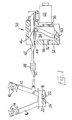
- the mechanism also comprises apparatus shown in Figure 1 for shearing gobs from the molten glass flowing out through the opening.
- the shearing apparatus shown in Figure 1 comprises a set of shear blades comprising two blades 10 mounted on an arm 12 and two co-operating blades 14 mounted on an arm 16.
- the set of shear blades is arranged to shear two gobs simultaneously with each blade 10 co-operating with one of the blades 14 to shear through the molten glass.
- the arms 12 and 16 are mounted for pivoting movement about pivot pins 18 and 20 respectively to move the blades 10 and 14 along arcuate paths towards and away from one another between open (shown in Figure 1) and shearing positions thereof.
- the arm 12 has a portion 22 thereof which is arcuate about the pin 18 formed with teeth which mesh with similar teeth formed on a portion 24 of the arm 16 which is arcuate about the pin 20. Through the meshing of the teeth on the portions 22 and 24, it is ensured that, when the arm 12 moves pivotally about the pin 18, the arm 16 makes an equal pivotal movement about the pin 20 but in the opposite direction.
- the shearing apparatus also comprises a driving system 30 arranged to drive the shear blades 10 and 14 by moving the arm 12 pivotally about the pin 18.
- the driving system comprises a box 32 within which a cylindrical cam 34 is mounted.
- the cam 34 is fixedly mounted on a shaft 36 which is rotatable in bearings 38 supported by the box 32 so that the cam 34 can be rotated about its central axis.
- a cam track 40 is formed in the outer curved surface of the cam 34.
- the cam track 40 is in the .shape of a sine wave and is in the form of a con- tiriuous groove around the cam 34.
- the system 30 also comprises a link 42 which is.slidable longitudinally thereof and parallel to the longitudinal axis of the cam 34 on bearings 44 supported by the box 32.
- a cam follower in the form of a roller 46 is mounted on the link 42 so that the roller 46 can rotate about an axis which extends transversely of the link 42 and radially of the cam 34.
- the roller 46 is received in the cam track 40 in which it fits closely so that rotation of the cam 34 causes the link 42 to slide on the bearings 44 between limits defined by the shape of the cam track 40.
- the link 42 is connected, via, an overload and overlap adjuster 48, to a further link 50 which is pivotally connected to the arm 12.
- the overload and overlap adjuster 48 allows an initial adjustment of the distance between the link 42 and the link 50 to fix the amount of overlap of the blades 10 and 14 in the shearing position thereof and the adjuster 48 also contains a strong spring which allows the distance between the link 42 and the link 50 to reduce if the blades 10 and 14 become jammed but, in normal operation, the distance between the link 42 and the link 50 is fixed.
- the arrangement is thus such that, as the cam 34 is rotated, the link 42 is caused to slide and the blades 10 and 14 are moved between their open and shearing positions.
- the open and shearing positions of the blades 10 and 14 depend on the stroke made by the link 42 which in turn depends on the extremes of the cam track 40.
- the driving system 30 also comprises a D.C. servomotor 52 which is arranged to drive the cam 34 about its axis.
- the motor 52 has the shaft 36 as its output shaft so that operation of the motor 52 is effective to rotate the cam 34.
- the driving system also comprises control means (not shown) arranged to generate electrical command signals to control the operation of the motor 52. These signals are derived from a stored programme to cause the shear blades 10 and 12 to be moved in accordance with a desired position against time curve, due account being taken of the shape of the cam track 34 in determining the magnitude of the signal.
- the control means may comprise a memory containing details of the desired position against time curve, a feedback device driven from the motor 52, and a computer arranged to continuously calculate the difference between the desired position of the motor 52 at a given time, as obtained from the memory, and the actual position of the motor at that time, as received from the feedback device, and to provide an appropriate driving signal to the motor 52.
- control signals are altered so that blades 10 and 14 move with a different position against time curve but the open and shearing positions of the blades 10 and 14 will remain unchanged as they are controlled by the shape of the cam track 40. It is thus possible to change the gob size without stopping the machine and no replacement of cams is necessary.
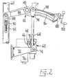
- the plunger driving means shown in Figure 2 is arranged to move a column 60 on which the plunger is mounted.
- the plunger driving means comprises a stroke device which determines the extreme positions reached by the plunger.
- the stroke device comprises a driving system 62 which is of similar construction to the driving system 30 having a cylindrical cam 64 with a cam track 66, a link 68 and a roller 70, the parts 64, 66, 68 and 70 being identical to the parts 34, 40, 42 and 46 respectively.
- the driving system 62 is mounted on a bracket 72 for pivoting movement about a pivot pin 74.
- the driving system 62 also comprises a D.C. servo-motor 76 which is identical to the motor 52.
- the driving system 62 causes the link 68 to move through a stroke whose limits are defined by the shape of the cam track 66 and this stroke is transmitted to the column 60 by a lever arrangement of the stroke device.
- the lever arrangement of the stroke device comprises a fixed pivot 80 on which a lever 82 is mounted for pivoting movement.
- the lever 82 comprises a first portion 84 which is to the left of the pivot 80 viewing Figure 2 and a second portion 86 which is to the right of the pivot 80 viewing Figure 2.
- the portion 84 of the lever 82 is pivotally connected to a link 88 which is in turn connected to the column 60 via a connection 90 which can be moved along the column 60 by means of an adjusting screw 92.
- the portion 86 of the lever 82 forms an arcuate slideway on which a block 94 to which the link 68 is connected is movable towards or away from the pivot 80.
- the block 94 can be moved along the slideway by means of an adjustment screw 98 which is supported by a bracket 100 carried by the portion 86.
- the screw 98 can be turned by means of a handle 102.
- the arrangement is such that by turning the handle 102, the block 94 can be moved relative to the pivot 80 and the point at which the rod 68 acts on the lever 82 can be moved. Movement of the block 94 towards the pivot 80 increases the movement made by the column 60 during a stroke of the stroke device while movement of the block 94 away from the pivot 80 decreases this movement. When the block 94 is moved the driving system 62 pivots about the pin 74 to accommodate the movement.
Description
- This invention is concerned with a feeder mechanism for supplying gobs of plastic material e.g. molten glass, the mechanism comprising a plunger driving means operable to move a plunger into and out of an opening in the bottom of a channel containing plastic material so that, when the plunger is out of the opening, the plastic material flows out through the opening, and apparatus for shearing gobs from the material flowing out through the opening, the apparatus comprising a set of shear blades movable towards and away from one another between open and shearing positions thereof, and a driving system arranged to drive the shear blades.
- In the operation of a glass container forming machine, a feeder mechanism as described above supplies gobs of molten glass which are moulded into containers by the machine. It is necessary that the shear blades of the mechanism perform a precise stroke between an overlapping shearing position and an open position thereof. The length of the stroke is constant for all working conditions of the feeder mechanism but it is necessary to vary the speed and relative timings of different portions of the stroke, when changing from gobs of one size to gobs of another size or when changing the shape of the gob, since there is a different desired position against time curve for the blades for each size and shape of gob.
- In order to achieve the desired position against time curve for a particular gob, present feeder mechanisms each comprise a driving system for the shear blades which comprises a plate cam having an edge profile in accordance with the desired position against time curve for the blades, a cam follower running on the edge of the cam being mechanically connected to the blades. The cam is rotated continuously in the operation of the machine at a constant speed so that successive strokes of the shear blades are made with the position against time curve of the shear blades being determined entirely by the shape of the cam. A feeder mechanism of the above-identified type is described in "Glass Machines" edited by W. Giegerich and W. Trier published by Springer-Verlag in 1969 on pages 152 to 158. Another example of shear blades driven by a plate cam can be found in US-A-2472560. DE-B1-2818234 describes shear blades driven by a cam with a cam track which is rotated. A part of the cam track is arcuate about the centre of rotation of the cam and represents "dead time" during which the blades rest in an open position. There is provision for varying the "dead time" by driving the cam at different speeds when the arcuate part of the cam track is operational. However, the stroke of the blades is made with a position against time curve which is determined entirely by the shape of the cam. With present feeders, when a gob of a different size or shape is to be produced, the cam is removed and replaced by another having a different profile. It is usually necessary to maintain a supply of alternative cams. Furthermore, it is not possible to vary the position against time curve without producing a new cam and stopping the machine to fit it.
- It is an object of the present invention to provide a feeder mechanism in which the position against time curve of the shear blades can be varied without requiring a new cam and without requiring the machine to be stopped.
- The invention provides a feeder mechanism for supplying gobs of plastic material, e.g. molten glass, the mechanism comprising a plunger driving means operable to move a plunger into and out of an opening in the bottom of a channel containing the plastic material so that, when the plunger is out of the opening, the plastic material flows out through the opening, and apparatus for shearing gobs from the material flowing out through the opening, the apparatus comprising a set of shear blades movable towards and away from one another between open and shearing positions thereof, and a driving system arranged to drive the shear blades, the driving system for the shear blades comprising a link connected to the shear blades and mounted for linear movement to move the shear blades as aforesaid, a cam mounted for rotation and driven to rotate about a central axis thereof, the cam having a cam track, and a cam follower mounted on the link and engaging the cam track so that rotation of the cam about its axis causes linear movement of the link thereby moving the shear blades between limits defined by the shape of the cam track, characterised in that the cam is arranged to be driven about its axis by a servo-motor at a speed which is varied in accordance with control signals derived from a stored programme to thereby move the shear blades in accordance with a desired position against time curve.
- In a feeder mechanism according to the invention, the driving system for the shear blades does not involve any cams which require replacement and thus avoids the necessity to maintain a supply of cams. If it is desired to vary the position against time curve of the shear blades, the stored programme can be altered to affect this change. Indeed, it is possible to affect this change without stopping the machine. The use of the cam track to) define the limits of the movement ensures that the open and shearing positions of the blades are precisely defined. Furthermore, the use of simpler cams is possible since the cam track can have a simple shape.
- Preferably, the cam track is in the form of a continuous groove which closely fits the cam follower.
- The programming of the mechanism can be simplified if the cam track is in the shape of a sine wave.
- In present feeder mechanisms, the plunger driving means is similar to the driving system for the shear blades in that it comprises a continuously driven plate cam having an edge profile in accordance with the desired position against time curve for the plunger. Accordingly, as the plunger movements require to be altered for different gobs, it is necessary to maintain a supply of alternative cams. Such cams also incorporate different extreme positions for the plunger since different strokes of the plunger may be of different length. In order to avoid the necessity for maintaining a supply of cams for the plunger driving means and also because it is generally convenient to operate the driving system of the shear blades and the plunger driving means on a similar principle, according to a further arrangement of the invention the plunger driving means comprises a stroke device which determines the extreme positions reached by the plunger, the stroke device having an adjustable stroke, and a driving system for the stroke device, the driving system for the stroke device comprising a further link connected to the stroke device and mounted for linear movement to cause the stroke device to move the plunger, a further cam mounted for rotation about a central axis thereof, the further cam having a further cam track, a further cam follower mounted on the further link and engaging the further cam track so that rotation of the further cam about its axis causes linear movement of the further link, the further cam being arranged to be driven about its axis by a further servo-motor at a speed which is varied in accordance with control signals derived from a stored programme to thereby move the further link in accordance with a desired position against time curve between limits defined by the shape of the further cam track.
- There now follows a detailed description, to be read with reference to the accompanying drawings, of a feeder mechanism which is illustrative of the invention. It is to be understood that the illustrative feeder mechanism has been selected for description by way of example and not of limitation of the invention as defined in the claims.
- In the drawings:
- Figure 1 is a diagrammatic view of shear blades and associated parts of the illustrative feeder mechanism; and
- Figure 2 is a diagrammatic view of plunger moving means of the illustrative feeder mechanism.
- The Figures show portions of a feeder mechanism in accordance with the invention. The feeder mechanism is for supplying gobs of molten glass. The mechanism comprises a plunger driving means shown in Figure 2 which is operable to move a plunger (not shown) into and out of an opening in the bottom of a channel (not shown). The channel contains molten glass and, in conventional manner, when the plunger is out of the opening, the molten glass flows out through the opening. The mechanism also comprises apparatus shown in Figure 1 for shearing gobs from the molten glass flowing out through the opening.
- The shearing apparatus shown in Figure 1 comprises a set of shear blades comprising two
blades 10 mounted on anarm 12 and twoco-operating blades 14 mounted on anarm 16. The set of shear blades is arranged to shear two gobs simultaneously with eachblade 10 co-operating with one of theblades 14 to shear through the molten glass. Thearms pivot pins blades arm 12 has aportion 22 thereof which is arcuate about thepin 18 formed with teeth which mesh with similar teeth formed on aportion 24 of thearm 16 which is arcuate about thepin 20. Through the meshing of the teeth on theportions arm 12 moves pivotally about thepin 18, thearm 16 makes an equal pivotal movement about thepin 20 but in the opposite direction. - The shearing apparatus also comprises a
driving system 30 arranged to drive theshear blades arm 12 pivotally about thepin 18. The driving system comprises abox 32 within which acylindrical cam 34 is mounted. Thecam 34 is fixedly mounted on ashaft 36 which is rotatable inbearings 38 supported by thebox 32 so that thecam 34 can be rotated about its central axis. Acam track 40 is formed in the outer curved surface of thecam 34. Thecam track 40 is in the .shape of a sine wave and is in the form of a con- tiriuous groove around thecam 34. Thesystem 30 also comprises alink 42 which is.slidable longitudinally thereof and parallel to the longitudinal axis of thecam 34 onbearings 44 supported by thebox 32. A cam follower in the form of aroller 46 is mounted on thelink 42 so that theroller 46 can rotate about an axis which extends transversely of thelink 42 and radially of thecam 34. Theroller 46 is received in thecam track 40 in which it fits closely so that rotation of thecam 34 causes thelink 42 to slide on thebearings 44 between limits defined by the shape of thecam track 40. Thelink 42 is connected, via, an overload and overlap adjuster 48, to afurther link 50 which is pivotally connected to thearm 12. The overload andoverlap adjuster 48 allows an initial adjustment of the distance between thelink 42 and thelink 50 to fix the amount of overlap of theblades adjuster 48 also contains a strong spring which allows the distance between thelink 42 and thelink 50 to reduce if theblades link 42 and thelink 50 is fixed. The arrangement is thus such that, as thecam 34 is rotated, thelink 42 is caused to slide and theblades blades link 42 which in turn depends on the extremes of thecam track 40. - The
driving system 30 also comprises aD.C. servomotor 52 which is arranged to drive thecam 34 about its axis. Themotor 52 has theshaft 36 as its output shaft so that operation of themotor 52 is effective to rotate thecam 34. The driving system also comprises control means (not shown) arranged to generate electrical command signals to control the operation of themotor 52. These signals are derived from a stored programme to cause theshear blades cam track 34 in determining the magnitude of the signal. The control means may comprise a memory containing details of the desired position against time curve, a feedback device driven from themotor 52, and a computer arranged to continuously calculate the difference between the desired position of themotor 52 at a given time, as obtained from the memory, and the actual position of the motor at that time, as received from the feedback device, and to provide an appropriate driving signal to themotor 52. - When it is desired to change the size or shape of the gob, the control signals are altered so that
blades blades cam track 40. It is thus possible to change the gob size without stopping the machine and no replacement of cams is necessary. - The plunger driving means shown in Figure 2 is arranged to move a
column 60 on which the plunger is mounted. The plunger driving means comprises a stroke device which determines the extreme positions reached by the plunger. The stroke device comprises adriving system 62 which is of similar construction to thedriving system 30 having acylindrical cam 64 with acam track 66, alink 68 and aroller 70, theparts parts system 62 is mounted on abracket 72 for pivoting movement about apivot pin 74. The drivingsystem 62 also comprises a D.C. servo-motor 76 which is identical to themotor 52. - Under the action of the
motor 76, which is controlled by similar control means to themotor 52, the drivingsystem 62 causes thelink 68 to move through a stroke whose limits are defined by the shape of thecam track 66 and this stroke is transmitted to thecolumn 60 by a lever arrangement of the stroke device. - The lever arrangement of the stroke device comprises a fixed
pivot 80 on which alever 82 is mounted for pivoting movement. Thelever 82 comprises afirst portion 84 which is to the left of thepivot 80 viewing Figure 2 and asecond portion 86 which is to the right of thepivot 80 viewing Figure 2. Theportion 84 of thelever 82 is pivotally connected to alink 88 which is in turn connected to thecolumn 60 via a connection 90 which can be moved along thecolumn 60 by means of an adjustingscrew 92. Theportion 86 of thelever 82 forms an arcuate slideway on which ablock 94 to which thelink 68 is connected is movable towards or away from thepivot 80. Theblock 94 can be moved along the slideway by means of anadjustment screw 98 which is supported by abracket 100 carried by theportion 86. Thescrew 98 can be turned by means of ahandle 102. - The arrangement is such that by turning the
handle 102, theblock 94 can be moved relative to thepivot 80 and the point at which therod 68 acts on thelever 82 can be moved. Movement of theblock 94 towards thepivot 80 increases the movement made by thecolumn 60 during a stroke of the stroke device while movement of theblock 94 away from thepivot 80 decreases this movement. When theblock 94 is moved the drivingsystem 62 pivots about thepin 74 to accommodate the movement. - It will be apparent that it is not necessary to change cams when using the illustrative feeder mechanism and the position against time curve of the shear blades can be changed without stopping the machine.
Claims (6)
Applications Claiming Priority (2)
| Application Number | Priority Date | Filing Date | Title |
|---|---|---|---|
| GB8219985 | 1982-07-09 | ||
| GB8219985 | 1982-07-09 |
Publications (3)
| Publication Number | Publication Date |
|---|---|
| EP0100598A2 EP0100598A2 (en) | 1984-02-15 |
| EP0100598A3 EP0100598A3 (en) | 1985-04-17 |
| EP0100598B1 true EP0100598B1 (en) | 1987-06-24 |
Family
ID=10531584
Family Applications (1)
| Application Number | Title | Priority Date | Filing Date |
|---|---|---|---|
| EP83303777A Expired EP0100598B1 (en) | 1982-07-09 | 1983-06-30 | Feeder mechanism for supplying gobs of plastic material |
Country Status (5)
| Country | Link |
|---|---|
| US (1) | US4544397A (en) |
| EP (1) | EP0100598B1 (en) |
| JP (1) | JPS5921531A (en) |
| AU (1) | AU1669983A (en) |
| DE (1) | DE3372205D1 (en) |
Families Citing this family (12)
| Publication number | Priority date | Publication date | Assignee | Title |
|---|---|---|---|---|
| US4548637A (en) * | 1984-08-30 | 1985-10-22 | Owens-Illinois, Inc. | Servo-control of machine motions in manufacture of glass containers |
| JPS61259207A (en) * | 1985-05-14 | 1986-11-17 | Mitsubishi Rayon Co Ltd | Optical conductor and its production and cylinder body used therfor |
| GB2249090B (en) * | 1990-10-22 | 1994-04-06 | Heye Hermann | Apparatus for severing gobs from glass streams |
| DE4104495C1 (en) * | 1991-02-14 | 1992-02-06 | Fa. Hermann Heye, 3063 Obernkirchen, De | |
| US5379667A (en) * | 1991-10-28 | 1995-01-10 | General Tire | Pinch cutting method and apparatus |
| US5885317A (en) * | 1993-02-25 | 1999-03-23 | Owens-Brockway Glass Container Inc. | Multiple orifice glass feed system |
| DE9411572U1 (en) * | 1994-07-16 | 1994-09-15 | Heye Hermann Fa | Separating device for items of glass strands |
| US6905587B2 (en) * | 1996-03-22 | 2005-06-14 | Ronald Redline | Method for enhancing the solderability of a surface |
| US6705355B1 (en) * | 2000-04-03 | 2004-03-16 | Yair Wiesenfeld | Wire straightening and cut-off machine and process |
| DE102004022218A1 (en) * | 2004-05-04 | 2005-12-01 | Heye International Gmbh | Method and device for producing different glass gob masses in the manufacture of glass articles |
| DE102009006911A1 (en) * | 2009-01-30 | 2010-08-05 | Weber Maschinenbau Gmbh Breidenbach | Knife for cutting food products |
| DE102009022969B4 (en) * | 2009-05-28 | 2016-08-04 | Wafios Ag | Cutting system for wire processing machines |
Family Cites Families (7)
| Publication number | Priority date | Publication date | Assignee | Title |
|---|---|---|---|---|
| CA641944A (en) * | 1962-05-29 | A. Dahlman Frederick | Glass feeder shear mechanism activating means | |
| US1304568A (en) * | 1919-05-27 | Glass gathering machine and process, | ||
| US2472560A (en) * | 1946-11-20 | 1949-06-07 | Hartford Empire Co | Glass feeder shear mechanism actuating means |
| US2956371A (en) * | 1957-10-17 | 1960-10-18 | Kimble Glass Co | Insulated shear mechanism |
| US3996037A (en) * | 1974-02-08 | 1976-12-07 | Emhart Industries, Inc. | Pass through shears for molten glass feeder |
| DE2818234C2 (en) * | 1978-04-26 | 1980-07-17 | Jenaer Glaswerk Schott & Gen., 6500 Mainz | Glass scissors |
| US4388100A (en) * | 1981-12-08 | 1983-06-14 | Vitro Tec Fideicomiso | Shear mechanism for machines for the manufacture of articles of glass or other materials |
-
1983
- 1983-06-30 EP EP83303777A patent/EP0100598B1/en not_active Expired
- 1983-06-30 DE DE8383303777T patent/DE3372205D1/en not_active Expired
- 1983-07-05 US US06/510,866 patent/US4544397A/en not_active Expired - Fee Related
- 1983-07-08 AU AU16699/83A patent/AU1669983A/en not_active Abandoned
- 1983-07-08 JP JP58125369A patent/JPS5921531A/en active Pending
Non-Patent Citations (1)
| Title |
|---|
| W. Giegerich & W. Trier, "Glass Machines", 1969, Springer Verlag, Berlin, Heidelberg, New York, pages 152-158 * |
Also Published As
| Publication number | Publication date |
|---|---|
| AU1669983A (en) | 1984-01-12 |
| JPS5921531A (en) | 1984-02-03 |
| US4544397A (en) | 1985-10-01 |
| DE3372205D1 (en) | 1987-07-30 |
| EP0100598A2 (en) | 1984-02-15 |
| EP0100598A3 (en) | 1985-04-17 |
Similar Documents
| Publication | Publication Date | Title |
|---|---|---|
| EP0100598B1 (en) | Feeder mechanism for supplying gobs of plastic material | |
| US4996866A (en) | Orientable bending assembly | |
| US4833989A (en) | Axially shiftable sheet gripper assembly | |
| CN101712021A (en) | Device capable of automatically adjusting coating machine scraper gap | |
| EP0164902B1 (en) | Straight-line shearing | |
| JP2677379B2 (en) | Device for changing the degree of opening between a welding element and an opposing welding element in a packaging machine | |
| US4637338A (en) | Scraping apparatus | |
| EP0706977B1 (en) | Glass gob shearing apparatus | |
| US4357158A (en) | Gob distributor for the shaping of articles of glass and other materials | |
| US4562669A (en) | Machine for grinding cylindrical workpieces | |
| EP0273559A1 (en) | Apparatus for distributing gobs in a bottle making machine | |
| US4939967A (en) | Cut-off machine | |
| RU2733494C2 (en) | Method and device for cutting dough produced by an extrusion machine | |
| US4261674A (en) | Gear cutting machine and method | |
| US3205746A (en) | Glass shears | |
| US5188653A (en) | Apparatus for severing gobs from glass streams | |
| EP0251814A2 (en) | Engraving machine | |
| SU967774A1 (en) | Profiling machine | |
| US5637128A (en) | Gob distributor for glassware forming machines or for other materials | |
| JP2511124B2 (en) | Web feeder | |
| US2990753A (en) | Method of and apparatus for making plate-and cylinder cams | |
| US4467683A (en) | Shear mechanism for glass feeder | |
| CN107470545A (en) | The excision forming device of screw forming machine | |
| JP2549351B2 (en) | Mold opener for bottle making machine | |
| GB2108034A (en) | Cutting device for cutting web material |
Legal Events
| Date | Code | Title | Description |
|---|---|---|---|
| PUAI | Public reference made under article 153(3) epc to a published international application that has entered the european phase |
Free format text: ORIGINAL CODE: 0009012 |
|
| AK | Designated contracting states |
Designated state(s): DE FR GB IT |
|
| PUAL | Search report despatched |
Free format text: ORIGINAL CODE: 0009013 |
|
| AK | Designated contracting states |
Designated state(s): DE FR GB IT |
|
| 17P | Request for examination filed |
Effective date: 19850724 |
|
| 17Q | First examination report despatched |
Effective date: 19860505 |
|
| GRAA | (expected) grant |
Free format text: ORIGINAL CODE: 0009210 |
|
| AK | Designated contracting states |
Kind code of ref document: B1 Designated state(s): DE FR GB IT |
|
| REF | Corresponds to: |
Ref document number: 3372205 Country of ref document: DE Date of ref document: 19870730 |
|
| ET | Fr: translation filed | ||
| ITF | It: translation for a ep patent filed |
Owner name: UFFICIO BREVETTI RICCARDI & C. |
|
| PLBE | No opposition filed within time limit |
Free format text: ORIGINAL CODE: 0009261 |
|
| STAA | Information on the status of an ep patent application or granted ep patent |
Free format text: STATUS: NO OPPOSITION FILED WITHIN TIME LIMIT |
|
| 26N | No opposition filed | ||
| PG25 | Lapsed in a contracting state [announced via postgrant information from national office to epo] |
Ref country code: GB Effective date: 19880630 |
|
| GBPC | Gb: european patent ceased through non-payment of renewal fee | ||
| PG25 | Lapsed in a contracting state [announced via postgrant information from national office to epo] |
Ref country code: FR Free format text: LAPSE BECAUSE OF NON-PAYMENT OF DUE FEES Effective date: 19890228 |
|
| PG25 | Lapsed in a contracting state [announced via postgrant information from national office to epo] |
Ref country code: DE Effective date: 19890301 |
|
| REG | Reference to a national code |
Ref country code: FR Ref legal event code: ST |