EP0097465A1 - Diagnostic X-ray apparatus - Google Patents
Diagnostic X-ray apparatus Download PDFInfo
- Publication number
- EP0097465A1 EP0097465A1 EP83303378A EP83303378A EP0097465A1 EP 0097465 A1 EP0097465 A1 EP 0097465A1 EP 83303378 A EP83303378 A EP 83303378A EP 83303378 A EP83303378 A EP 83303378A EP 0097465 A1 EP0097465 A1 EP 0097465A1
- Authority
- EP
- European Patent Office
- Prior art keywords
- digital
- video signals
- analogue
- signals
- ray
- Prior art date
- Legal status (The legal status is an assumption and is not a legal conclusion. Google has not performed a legal analysis and makes no representation as to the accuracy of the status listed.)
- Granted
Links
Images

Classifications
-
- H—ELECTRICITY
- H04—ELECTRIC COMMUNICATION TECHNIQUE
- H04N—PICTORIAL COMMUNICATION, e.g. TELEVISION
- H04N5/00—Details of television systems
- H04N5/30—Transforming light or analogous information into electric information
- H04N5/32—Transforming X-rays
- H04N5/3205—Transforming X-rays using subtraction imaging techniques
-
- H—ELECTRICITY
- H05—ELECTRIC TECHNIQUES NOT OTHERWISE PROVIDED FOR
- H05G—X-RAY TECHNIQUE
- H05G1/00—X-ray apparatus involving X-ray tubes; Circuits therefor
- H05G1/08—Electrical details
- H05G1/64—Circuit arrangements for X-ray apparatus incorporating image intensifiers
Definitions
- This invention relates to diagnostic x-ray apparatus which makes use of a digital x-ray subtraction imaging technique, and more particularly to such apparatus having a master timing control unit.
- a digital x-ray subtraction imaging technique using an imaging intensifier-T.V. chain was developed and first described by Mistretta et al.
- U.S. Patent Nos. 4,204,225 and 4,204,226, in the name of Charles A. Mistretta a real-time digital x-ray subtraction imaging method and apparatus are disclosed.
- One of the digital x-ray subtraction imaging apparatuses includes an image intensifier, a T.V. camera the output of which is digitised and an image processor incorporating two digital memories.
- a second memory system integrates digital video signals and provides an output of these integrated video signals, from which the mask video signals from the first memory system are subtracted.
- the resulting digital difference video signals are supplied to a'digital-to-analogue converter which provides corresponding analogue difference video signals for display by a display device.
- the resulting analogue difference video signals may be fed to a multiformat camera for making a selected number of radiographic exposures on a single film.
- a series of difference images is produced by integrating digital video signals over a series of successive time intervals, performing a series of subtractions between the sets of successive integrated video signals stored in the memories to produce a series of digital difference video signals, and converting such digital difference video signals into visibly displayed difference images representing changes in the-x-ray image during the successive time intervals.
- One advatange of digital radiography apparatus is its capability to perform angiography by means of intravenous injection instead of intra-arterial catheter techniques with their higher risks.
- Still another advantage of digital radiography apparatus is its capability to provide improved low contrast detectability, namely, to amplify subtle amounts of contrast media in arteries better than film methods can.
- Another advantage of digital radiography apparatus employing pulsed x-rays is that significant loss of spatial resolution due to physiological motion can be prevented because the short radiation pulse for each image results in less loss of detail.
- These digital radiography apparatuses include a master timing control circuit which provides synchronisation and is connected to a slave timing control unit for controlling an associated memory unit.
- the T.V. camera operates in synchronisation with the system, via the master timing control which generates sync and blanking signals'for the camera video signals.
- the master timing control unit generally comprises a single-phase control clock, so that synchronisation erros arise between the sync signals produced by the video camera and a pixel clock via the master timing control circuit, which controls the memory unit for writing in the digital pixel signals.
- synchronisation errors cause mis- registration, and the artifacts from the mis-registration appear in the subtraction images.
- the artifacts from the mis-registration are especially harmful when the contrast between picture elements is rather low. It is desirable, therefore, to maintain improved spatial resolution and low contrast detectability by removing or minimising the synchronisation errors.
- the invention seeks to overcome the defects of previous digital radiography apparatus to provide subtraction images without the artifacts from mis- registration due to synchronisation errors, and to minimise significant misregistration due to synchronisation errors.
- the invention seeks to constrain synchronisation errors between the horizontal synchronising signals from the video camera and the synchronising signals from the master timing control unit to acceptably low levels.
- a diagnostic x-ray apparatus for producing visible difference images from x-ray images obtained from x-ray radiation comprising: an x-ray generating source for emitting x-ray radiation to produce an x-ray image; a television camera for converting the x-ray image into a series of television images comprising trains of analogue video signals; an analogue-to-digital converter for converting the analogue video signals into corresponding digital video signals; a digital memory system including at least two digital memory means for storing and integrating the digital video signals in a predetermined sequence; subtracting means for producing digital difference video signals by performing a subtraction between the recent digital video signals stored in the digital memory system and preceding digital video signals stored in the digital memory system; a digital-to-analogue converter for converting digital difference video signals into analogue difference video signals; synchronising means including means for generating a plurality of clock pulses in a predetermined time relationship and means for selecting one clock pulse out of said plurality of clock pulses according to a predetermined formula, and means responsive
- diagnostic x-ray apparatus using real time digital processing of x-ray transmission often includes a conventional T.V. fluoroscopy system employing real time digital processing hardware.
- an x-ray tube 10 has a conventional filament and an anode which produces x-rays which impinge upon a patient 12, thus casting a shadow image of the patient on an input of an image intensifier tube 14.
- a servo-controlled collimator 16 which has a collimator servo system (not shown) is disposed between the x-ray tube 10 and the patient, and controls the size of the x-ray beam emitted from the x-ray tube 10.
- the intensifier 14 intensifies the x-ray image and produces a corresponding optical image on the output screen of the intensifier 14.
- This image is scanned by a T.V. camera 18, via a known optical system 20 including an object lens, a field lens (not shown) and auto iris (not shown) for adjusting the quantity of light from the intensifier 14, under control of a T.V. camera control unit (not shown) to produce corresponding video signals on an output of the T.V. camera 18.
- An x-ray generator 22 serves to provide a high voltage to energise the x-ray tube 10 under control of an x-ray control unit (not shown).
- the x-ray generator 22- is also connected to a master timing control unit which will be described in detail later, so that x-ray tube 10 is pulsed on and off at regular intervals according to the requirement of the various imaging models.
- Subtraction is a known technique that is used to remove overlying and underlying structures after the object of interest is enhanced by a contrast medium. Images are acquired before and after the contrast medium is present and these images are subtracted.
- the contrast medium is preferably injected into the right basilic vein of the patient 12 using a high-pressure injector 24 synchronised with the operation of the x-ray generator 22.
- An analogue-to-digital interface circuit 26 including a sync stripper separates the vertical and horizontal synchronising pulses from the video information provided from the camera 18 to provide video signals without the synchronising pulses. These video signals are applied to a gate circuit and to an analogue-to-digital converter for converting analogue video signals provided at the output of the gate circuit into corresponding digital video signals.
- the master timing control unit 36 supplies clock and gating or control, pulses to the analogue-to-digital interface circuit 26.
- the digital video output of the analogue-to-digital interface circuit 26 is supplied to a video image processing unit 28.
- the video image processor 28 includes two memory systems 30, 32, for integrating and storing the digital video signals over a series of time intervals, and an arithmetic logic unit 34 for enabling the memories 30, 32 to integrate and- store the digital video signals over the series of time intervals.
- the processor 28 also produces digital difference video signals by performing subtraction between the set of integrated digital video signals stored in the most recently filled memory system 32 and the set stored in the previously filled memory system 30 in response to timing signals initiated by the master timing control unit 36.
- the digital difference video signals are supplied to a digital-to-analogue interface circuit 38 which provides corresponding analogue difference video signals for display by a CRT monitor 40.
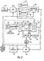
- Figure 2 includes a detailed circuit diagram of the master control circuit 36 for providing all of the control, timing and synchronising pulses and signals for the entire system.
- the master timing control circuit 36 includes a local oscillator 42 for generating a basic clock at a frequency fl which amounts to one clock pulse every T nanoseconds (ns), the clock comprising a crystal oscillator 44 and a divider 46 driven by the crystal oscillator.
- T is 100 ns
- n being 5
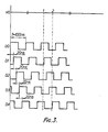
- five different clock pulses delayed by 20 ns with respect to the basic clock are generated as shown in Figure 3.
- the different clock pulses Dl-Dn from the delay circuit 48 are sampled by the latch circuit 50 in synchronism with the horizontal synchronising signals from the analogue-to-digital interface 26, and the sampled values are converted to quantified signals which substantially indicate the number of active lines.
- the quantified output data from the latch circuit 50 will be received by a random access memory 52, for later access, by-addressing the memory 52 in a predetermined sequence.
- a logic flag indicative of the status of the latch is furnished to the random access memory 52.
- a selector 54 receives the different clock pulses Dl-Dn from the delay circuit 48, and selects one of the different clock pulses in response to the logical read out of the memory 52.
- the output selected by the selector 54 is supplied to a synchronising signal generator 56 which provides synchronising signals to the digital-to-analogue interface circuit 38.
- the synchronising signal generator 56 is provided for generating horizontal and vertical sync signals.
- the digital difference video output from the arithmetic logic unit 34 is applied to the digital-to-analogue interface circuit 38 in conjunction with the horizontal and vertical synchronising pulses.
- the digital-to-analogue interface circuit 38 includes a digital-to-analogue converter for converting the composite video output from digital form into analogue video signals, which are then supplied to the CRT monitor 40 for display.
- a series of difference images is produced by developing a pre-injection mask image, prior to the injection of the contrast medium, and electronically subtracting the mask image from each of a series of post-injection images.
- This mask subtraction mode results in the removal of effects due to soft tissue and bone or air-filled structures, so that the image elements due to the contrast medium are clearly visible in the subtracted images.
- An alternative method offered by the subtraction technique is the use of the time interval difference method, in which each set of integrated digital images is used as a mask for the following integrated digital image.
- the time interval difference method is particularly well adapted for visualising the progress of a contrast medium injected into a peripheral portion of the cardiovascular system.
- the amplified analogue video signals from the T.V. camera 18 are supplied to the A/D interface circuit 26 which gates the analogue video signals, separates the horizontal and vertical sync pulses from the gated analogue signals, and digitises the gated signals in the analogue-to-digital converter periodically, as determined by the synchronisating clock pulses from the synchronising clock pulse generator 56.
- the A/D interface circuit 26 applies corresponding digital video signals to the mask producing memory system 30 where a first image serving as the mask for the subtraction is made before the contrast medium injection, and also to the second memory system 32 storing the post-injection image.
- the mask image in the first memory system 30 is subtracted by the arithmetic logic unit 34 from the integrated subsequent video signals from the second memory system 32.
- the digital difference video signals of the subtracted result are supplied from the arithmetic logic unit 34 to the D/A interface circuit 38.
- the first memory system 30, the second memory system 32, and the arithmetic logic unit 34 are in synchronisation with the synchronising clock pulses generated by the synchronising clock pulse generator 56.
- the synchronising clock generator 56 generates the synchronising clock pulses in response to the output of the selector 54 which selects one of the different delayed pulses Dl-D4 in proper phase with the horizontal synchronising pulses separated by the stripper of the A/D interface circuit 26.
- the selector 54 operates in response to the stored data representing the delayed pulses in accordance with a predetermined formula in conjunction with the latch status.
- the delayed pulses D1-D4 are successively transmitted in parallel to the latch 50 which generates the address sequence used for reading data from the random access memory 52 coincident with occurrence of the horizontal sync pulses.
- the synchronising clock pulses used for keeping the entire system in a proper phase relationship employ the basic pulse DO before occurrence of the horizontal sync pulse separated in the A/D interface circuit 26.
- Horizontal sync pulses separated in the A/D interface circuit 26 are supplied repeatedly as, for instance, every 63.5 micro-seconds, shown by the waveform which is labelled H S in Figure 3.
- the different delayed clock pulses which are marked D1-D4 are delayed by 20 ns with respect to the basic clock D0. If the latch 50 operates in response to the horizontal sync pulse occurring as indicated at 1 in lines HS of Figure 3, the status of the latch 50 will be assigned to the logic (1, 0, 0, 0, 1) corresponding to the presence of the delayed pulses.
- the signal being converted by the RAM 52 representing the delayed pulse Dl in accordance with the TABLE 1 is supplied to the selector 54.
- the delayed pulse Dl is used as the synchronising clock pulse instead of the basic pulse D0.
- the status of the latch 50 will be assigned the logic (0, 0, 1, 1, 0).
- the signal being converted by the RAM 52 representing the delayed pulse D4 in accordance with the TABLE 1 is supplied to the selector 54.
- the delayed pulse D4 is used as the synchronising clock pulse, which in turn is replaced by the delayed pulse D1.
- the synchronising clock pulse for the entire system is selected in a proper phase relationship out of a plurality of delayed clock pulses coincident with occurence of the horizontal sync pulse coming from the A/D interface circuit 26.
- any number n of delayed clock pulses should be obtainable by those skilled in the art.
Abstract
Description
- This invention relates to diagnostic x-ray apparatus which makes use of a digital x-ray subtraction imaging technique, and more particularly to such apparatus having a master timing control unit.
- A digital x-ray subtraction imaging technique using an imaging intensifier-T.V. chain was developed and first described by Mistretta et al. In, for example, U.S. Patent Nos. 4,204,225 and 4,204,226, in the name of Charles A. Mistretta, a real-time digital x-ray subtraction imaging method and apparatus are disclosed. One of the digital x-ray subtraction imaging apparatuses includes an image intensifier, a T.V. camera the output of which is digitised and an image processor incorporating two digital memories. As dislcosed in U.S. Patent No. 4,204,225, it is preferable when carrying out the mask mode of this process to employ a first memory to integrate and store digitised mask video signals from an image intensifier-T.V. chain during an initial mask time interval utilising a relatively large number of television fields. A second memory system integrates digital video signals and provides an output of these integrated video signals, from which the mask video signals from the first memory system are subtracted. The resulting digital difference video signals are supplied to a'digital-to-analogue converter which provides corresponding analogue difference video signals for display by a display device. Alternatively, the resulting analogue difference video signals may be fed to a multiformat camera for making a selected number of radiographic exposures on a single film.
- In the time interval difference mode disclosed in U.S. Patent No. 4,204,226, a series of difference images is produced by integrating digital video signals over a series of successive time intervals, performing a series of subtractions between the sets of successive integrated video signals stored in the memories to produce a series of digital difference video signals, and converting such digital difference video signals into visibly displayed difference images representing changes in the-x-ray image during the successive time intervals.
- One advatange of digital radiography apparatus is its capability to perform angiography by means of intravenous injection instead of intra-arterial catheter techniques with their higher risks.
- Still another advantage of digital radiography apparatus is its capability to provide improved low contrast detectability, namely, to amplify subtle amounts of contrast media in arteries better than film methods can.
- Another advantage of digital radiography apparatus employing pulsed x-rays is that significant loss of spatial resolution due to physiological motion can be prevented because the short radiation pulse for each image results in less loss of detail.
- These digital radiography apparatuses include a master timing control circuit which provides synchronisation and is connected to a slave timing control unit for controlling an associated memory unit. The T.V. camera operates in synchronisation with the system, via the master timing control which generates sync and blanking signals'for the camera video signals.
- In the prior art systems, the master timing control unit generally comprises a single-phase control clock, so that synchronisation erros arise between the sync signals produced by the video camera and a pixel clock via the master timing control circuit, which controls the memory unit for writing in the digital pixel signals. These synchronisation errors cause mis- registration, and the artifacts from the mis- registration appear in the subtraction images. The artifacts from the mis-registration are especially harmful when the contrast between picture elements is rather low. It is desirable, therefore, to maintain improved spatial resolution and low contrast detectability by removing or minimising the synchronisation errors.
- The invention seeks to overcome the defects of previous digital radiography apparatus to provide subtraction images without the artifacts from mis- registration due to synchronisation errors, and to minimise significant misregistration due to synchronisation errors.
- The invention seeks to constrain synchronisation errors between the horizontal synchronising signals from the video camera and the synchronising signals from the master timing control unit to acceptably low levels.
- A diagnostic x-ray apparatus for producing visible difference images from x-ray images obtained from x-ray radiation comprising: an x-ray generating source for emitting x-ray radiation to produce an x-ray image; a television camera for converting the x-ray image into a series of television images comprising trains of analogue video signals; an analogue-to-digital converter for converting the analogue video signals into corresponding digital video signals; a digital memory system including at least two digital memory means for storing and integrating the digital video signals in a predetermined sequence; subtracting means for producing digital difference video signals by performing a subtraction between the recent digital video signals stored in the digital memory system and preceding digital video signals stored in the digital memory system; a digital-to-analogue converter for converting digital difference video signals into analogue difference video signals; synchronising means including means for generating a plurality of clock pulses in a predetermined time relationship and means for selecting one clock pulse out of said plurality of clock pulses according to a predetermined formula, and means responsive to said selected pulse for producing synchronising signals for controlling the operation of the synchronising. signals for controlling the operation of the analogue-to-digital converter, the digital-to-analogue converter, the storing and integrating of the digital memory system, and the operation of said subtracting means; and a display or recording means for displaying or recording visible difference images corresponding to the analogue difference video signals.
- A preferred embodiment of the invention will now be described, by way of example and with reference to the accompanying drawings, wherein:
- Figure 1 is a block diagram of the embodiment of a diagnostic x-ray apparatus;
- Figure 2 is a detailed diagram of-an example of the master timing control unit of the embodiment of Figure 1; and
- Figure 3 is a timing diagram for the timing control unit of Figure 2.
- As indicated earlier, diagnostic x-ray apparatus using real time digital processing of x-ray transmission often includes a conventional T.V. fluoroscopy system employing real time digital processing hardware.
- Referring to the drawings, an
x-ray tube 10 has a conventional filament and an anode which produces x-rays which impinge upon apatient 12, thus casting a shadow image of the patient on an input of animage intensifier tube 14. A servo-controlledcollimator 16 which has a collimator servo system (not shown) is disposed between thex-ray tube 10 and the patient, and controls the size of the x-ray beam emitted from thex-ray tube 10. - The
intensifier 14 intensifies the x-ray image and produces a corresponding optical image on the output screen of theintensifier 14. This image is scanned by a T.V.camera 18, via a knownoptical system 20 including an object lens, a field lens (not shown) and auto iris (not shown) for adjusting the quantity of light from theintensifier 14, under control of a T.V. camera control unit (not shown) to produce corresponding video signals on an output of the T.V.camera 18. - An
x-ray generator 22 serves to provide a high voltage to energise thex-ray tube 10 under control of an x-ray control unit (not shown). The x-ray generator 22-is also connected to a master timing control unit which will be described in detail later, so thatx-ray tube 10 is pulsed on and off at regular intervals according to the requirement of the various imaging models. - Subtraction is a known technique that is used to remove overlying and underlying structures after the object of interest is enhanced by a contrast medium. Images are acquired before and after the contrast medium is present and these images are subtracted.
- The contrast medium is preferably injected into the right basilic vein of the
patient 12 using a high-pressure injector 24 synchronised with the operation of thex-ray generator 22. An analogue-to-digital interface circuit 26 including a sync stripper separates the vertical and horizontal synchronising pulses from the video information provided from thecamera 18 to provide video signals without the synchronising pulses. These video signals are applied to a gate circuit and to an analogue-to-digital converter for converting analogue video signals provided at the output of the gate circuit into corresponding digital video signals. The mastertiming control unit 36 supplies clock and gating or control, pulses to the analogue-to-digital interface circuit 26. - The digital video output of the analogue-to-
digital interface circuit 26 is supplied to a videoimage processing unit 28. Thevideo image processor 28 includes twomemory systems arithmetic logic unit 34 for enabling thememories processor 28 also produces digital difference video signals by performing subtraction between the set of integrated digital video signals stored in the most recently filledmemory system 32 and the set stored in the previously filledmemory system 30 in response to timing signals initiated by the mastertiming control unit 36. - The digital difference video signals are supplied to a digital-to-
analogue interface circuit 38 which provides corresponding analogue difference video signals for display by aCRT monitor 40. - Figure 2 includes a detailed circuit diagram of the
master control circuit 36 for providing all of the control, timing and synchronising pulses and signals for the entire system. - In Figure 2, the master
timing control circuit 36 includes alocal oscillator 42 for generating a basic clock at a frequency fl which amounts to one clock pulse every T nanoseconds (ns), the clock comprising acrystal oscillator 44 and adivider 46 driven by the crystal oscillator. - This basic clock at the frequency fl is applied to a
delay circuit 48 which provides a latch circuit 50 with a plurality of difference clock pulses Dl-Dn delayed by an amount T/n (n = an integer more than two), with respect to the basic clock. For example, assuming T is 100 ns, n being 5, five different clock pulses delayed by 20 ns with respect to the basic clock are generated as shown in Figure 3. - The different clock pulses Dl-Dn from the
delay circuit 48 are sampled by the latch circuit 50 in synchronism with the horizontal synchronising signals from the analogue-to-digital interface 26, and the sampled values are converted to quantified signals which substantially indicate the number of active lines. The quantified output data from the latch circuit 50 will be received by arandom access memory 52, for later access, by-addressing thememory 52 in a predetermined sequence. A logic flag indicative of the status of the latch is furnished to therandom access memory 52. Aselector 54 receives the different clock pulses Dl-Dn from thedelay circuit 48, and selects one of the different clock pulses in response to the logical read out of thememory 52. The output selected by theselector 54 is supplied to asynchronising signal generator 56 which provides synchronising signals to the digital-to-analogue interface circuit 38. Thesynchronising signal generator 56 is provided for generating horizontal and vertical sync signals. The digital difference video output from thearithmetic logic unit 34 is applied to the digital-to-analogue interface circuit 38 in conjunction with the horizontal and vertical synchronising pulses. The digital-to-analogue interface circuit 38 includes a digital-to-analogue converter for converting the composite video output from digital form into analogue video signals, which are then supplied to theCRT monitor 40 for display. - The operation of the apparatus according to the present invention can be most easily understoood by considering Figure 2 in conjunction with Figure 3.
- As previously described, in the so-called mask mode method, a series of difference images is produced by developing a pre-injection mask image, prior to the injection of the contrast medium, and electronically subtracting the mask image from each of a series of post-injection images. This mask subtraction mode results in the removal of effects due to soft tissue and bone or air-filled structures, so that the image elements due to the contrast medium are clearly visible in the subtracted images. An alternative method offered by the subtraction technique is the use of the time interval difference method, in which each set of integrated digital images is used as a mask for the following integrated digital image. The time interval difference method is particularly well adapted for visualising the progress of a contrast medium injected into a peripheral portion of the cardiovascular system.
- In order to digitise and store the information which serves as the mask or the subsequent series of images, the amplified analogue video signals from the T.V.
camera 18 are supplied to the A/D interface circuit 26 which gates the analogue video signals, separates the horizontal and vertical sync pulses from the gated analogue signals, and digitises the gated signals in the analogue-to-digital converter periodically, as determined by the synchronisating clock pulses from the synchronisingclock pulse generator 56. The A/D interface circuit 26 applies corresponding digital video signals to the mask producingmemory system 30 where a first image serving as the mask for the subtraction is made before the contrast medium injection, and also to thesecond memory system 32 storing the post-injection image. - Alternately, the mask image in the
first memory system 30 is subtracted by thearithmetic logic unit 34 from the integrated subsequent video signals from thesecond memory system 32. The digital difference video signals of the subtracted result are supplied from thearithmetic logic unit 34 to the D/A interface circuit 38. Thefirst memory system 30, thesecond memory system 32, and thearithmetic logic unit 34 are in synchronisation with the synchronising clock pulses generated by the synchronisingclock pulse generator 56. - The synchronising
clock generator 56 generates the synchronising clock pulses in response to the output of theselector 54 which selects one of the different delayed pulses Dl-D4 in proper phase with the horizontal synchronising pulses separated by the stripper of the A/D interface circuit 26. - The
selector 54 operates in response to the stored data representing the delayed pulses in accordance with a predetermined formula in conjunction with the latch status. The delayed pulses D1-D4 are successively transmitted in parallel to the latch 50 which generates the address sequence used for reading data from therandom access memory 52 coincident with occurrence of the horizontal sync pulses. - Conversions of the
RAM 52 are set forth in

- The synchronising clock pulses used for keeping the entire system in a proper phase relationship employ the basic pulse DO before occurrence of the horizontal sync pulse separated in the A/
D interface circuit 26. - Horizontal sync pulses separated in the A/
D interface circuit 26 are supplied repeatedly as, for instance, every 63.5 micro-seconds, shown by the waveform which is labelled H S in Figure 3. - In Figure 3, the different delayed clock pulses which are marked D1-D4 are delayed by 20 ns with respect to the basic clock D0. If the latch 50 operates in response to the horizontal sync pulse occurring as indicated at 1 in lines HS of Figure 3, the status of the latch 50 will be assigned to the logic (1, 0, 0, 0, 1) corresponding to the presence of the delayed pulses. The signal being converted by the
RAM 52 representing the delayed pulse Dl in accordance with the TABLE 1 is supplied to theselector 54. Thus, the delayed pulse Dl is used as the synchronising clock pulse instead of the basic pulse D0. On occurence of the next horizontal sync pulse marked 2 in line HS of Figure 3, the status of the latch 50 will be assigned the logic (0, 0, 1, 1, 0). The signal being converted by theRAM 52 representing the delayed pulse D4 in accordance with the TABLE 1 is supplied to theselector 54. Then, the delayed pulse D4 is used as the synchronising clock pulse, which in turn is replaced by the delayed pulse D1. - In this manner, the synchronising clock pulse for the entire system is selected in a proper phase relationship out of a plurality of delayed clock pulses coincident with occurence of the horizontal sync pulse coming from the A/
D interface circuit 26. - All the information representative of the delayed pulses established by the predetermined formula corresponding to 2n (n = an integer more than two) status of the latch 50 is stored in the
R AM 52. - Generally, any number n of delayed clock pulses, as required, should be obtainable by those skilled in the art.
Claims (4)
Applications Claiming Priority (2)
| Application Number | Priority Date | Filing Date | Title |
|---|---|---|---|
| JP57103027A JPS58220588A (en) | 1982-06-17 | 1982-06-17 | Video signal processor |
| JP103027/82 | 1982-06-17 |
Publications (2)
| Publication Number | Publication Date |
|---|---|
| EP0097465A1 true EP0097465A1 (en) | 1984-01-04 |
| EP0097465B1 EP0097465B1 (en) | 1987-05-06 |
Family
ID=14343158
Family Applications (1)
| Application Number | Title | Priority Date | Filing Date |
|---|---|---|---|
| EP83303378A Expired EP0097465B1 (en) | 1982-06-17 | 1983-06-10 | Diagnostic x-ray apparatus |
Country Status (4)
| Country | Link |
|---|---|
| US (1) | US4575752A (en) |
| EP (1) | EP0097465B1 (en) |
| JP (1) | JPS58220588A (en) |
| DE (1) | DE3371460D1 (en) |
Cited By (2)
| Publication number | Priority date | Publication date | Assignee | Title |
|---|---|---|---|---|
| EP0187427A1 (en) * | 1985-01-04 | 1986-07-16 | Yoshibumi Mukai | X-ray photographic apparatus |
| US6197941B1 (en) | 1996-09-30 | 2001-03-06 | Basf Aktiengesellschaft | Reactive dyes with a heterocyclic anchor |
Families Citing this family (9)
| Publication number | Priority date | Publication date | Assignee | Title |
|---|---|---|---|---|
| JPS63221491A (en) * | 1987-03-11 | 1988-09-14 | Victor Co Of Japan Ltd | Image data output device |
| JP2863161B2 (en) * | 1987-08-18 | 1999-03-03 | 松下電器産業株式会社 | Phase synchronous clock signal generator |
| US4878115A (en) * | 1987-09-25 | 1989-10-31 | University Of Kentucky Research Foundation | Dynamic coronary roadmapping |
| JPH02192698A (en) * | 1989-01-19 | 1990-07-30 | Toshiba Corp | X-ray high voltage device |
| GB2241620B (en) * | 1990-02-13 | 1994-11-30 | Matsushita Electric Ind Co Ltd | A pulse signal delay device |
| US5138459A (en) * | 1990-11-20 | 1992-08-11 | Personal Computer Cameras, Inc. | Electronic still video camera with direct personal computer (pc) compatible digital format output |
| FR2768235B1 (en) * | 1997-09-09 | 2000-02-04 | Aerospatiale | IMPROVED OPTOELECTRONIC OBSERVATION DEVICE FOR DETECTING LASER SHOTS |
| US6990368B2 (en) * | 2002-04-04 | 2006-01-24 | Surgical Navigation Technologies, Inc. | Method and apparatus for virtual digital subtraction angiography |
| US7129495B2 (en) * | 2004-11-15 | 2006-10-31 | General Electric Company | Method and apparatus for timing calibration in a PET scanner |
Citations (5)
| Publication number | Priority date | Publication date | Assignee | Title |
|---|---|---|---|---|
| DE2530315A1 (en) * | 1974-07-12 | 1976-01-29 | Wisconsin Alumni Res Found | DIFFERENTIAL ROENTGEN RADIATION PROCESS AND APPARATUS FOR PERFORMING ITS |
| DE2547120B2 (en) * | 1974-10-21 | 1976-11-11 | Nippon Telegraph And Telephone Public Corp., Tokio | PICTURE-TO-PICTURE COMPARISON ENCODING SYSTEM |
| US4181914A (en) * | 1976-12-20 | 1980-01-01 | Nippon Electric Co., Ltd. | System for reducing transmission problems in a parallel digital data transmission system |
| US4204226A (en) * | 1978-05-16 | 1980-05-20 | Wisconsin Alumni Research Foundation | Real-time digital X-ray time interval difference imaging |
| US4204225A (en) * | 1978-05-16 | 1980-05-20 | Wisconsin Alumni Research Foundation | Real-time digital X-ray subtraction imaging |
Family Cites Families (5)
| Publication number | Priority date | Publication date | Assignee | Title |
|---|---|---|---|---|
| US4285063A (en) * | 1979-06-08 | 1981-08-18 | Sperry Corporation | Apparatus for providing evenly delayed digital signals |
| JPS56126378A (en) * | 1980-03-10 | 1981-10-03 | Ricoh Co Ltd | Synchronous circuit of optical scanner |
| JPS5792984A (en) * | 1980-12-01 | 1982-06-09 | Seikosha Co Ltd | Circuit for generating synchronizing signal |
| US4393402A (en) * | 1981-06-08 | 1983-07-12 | General Electric Company | Subtraction fluoroscopy method and apparatus |
| US4467358A (en) * | 1982-02-09 | 1984-08-21 | Switsen Henry N | Video tape recorder signal processor |
-
1982
- 1982-06-17 JP JP57103027A patent/JPS58220588A/en active Granted
-
1983
- 1983-06-10 US US06/502,951 patent/US4575752A/en not_active Expired - Fee Related
- 1983-06-10 DE DE8383303378T patent/DE3371460D1/en not_active Expired
- 1983-06-10 EP EP83303378A patent/EP0097465B1/en not_active Expired
Patent Citations (5)
| Publication number | Priority date | Publication date | Assignee | Title |
|---|---|---|---|---|
| DE2530315A1 (en) * | 1974-07-12 | 1976-01-29 | Wisconsin Alumni Res Found | DIFFERENTIAL ROENTGEN RADIATION PROCESS AND APPARATUS FOR PERFORMING ITS |
| DE2547120B2 (en) * | 1974-10-21 | 1976-11-11 | Nippon Telegraph And Telephone Public Corp., Tokio | PICTURE-TO-PICTURE COMPARISON ENCODING SYSTEM |
| US4181914A (en) * | 1976-12-20 | 1980-01-01 | Nippon Electric Co., Ltd. | System for reducing transmission problems in a parallel digital data transmission system |
| US4204226A (en) * | 1978-05-16 | 1980-05-20 | Wisconsin Alumni Research Foundation | Real-time digital X-ray time interval difference imaging |
| US4204225A (en) * | 1978-05-16 | 1980-05-20 | Wisconsin Alumni Research Foundation | Real-time digital X-ray subtraction imaging |
Non-Patent Citations (1)
| Title |
|---|
| TOSHIBA REVIEW, INTERNATIONAL EDITION, no. 43, July-August 1969 M. NAKASHIKA, H. WATANABE, T. OKUBO, K. NISHIO, Y. WATASE "Latest Diagnostic System for Circulatory Organs", Publisher: Tokyo Shibaura Electric Co., Ltd.; pages 24-29 * |
Cited By (2)
| Publication number | Priority date | Publication date | Assignee | Title |
|---|---|---|---|---|
| EP0187427A1 (en) * | 1985-01-04 | 1986-07-16 | Yoshibumi Mukai | X-ray photographic apparatus |
| US6197941B1 (en) | 1996-09-30 | 2001-03-06 | Basf Aktiengesellschaft | Reactive dyes with a heterocyclic anchor |
Also Published As
| Publication number | Publication date |
|---|---|
| DE3371460D1 (en) | 1987-06-11 |
| JPH0218633B2 (en) | 1990-04-26 |
| US4575752A (en) | 1986-03-11 |
| JPS58220588A (en) | 1983-12-22 |
| EP0097465B1 (en) | 1987-05-06 |
Similar Documents
| Publication | Publication Date | Title |
|---|---|---|
| US4612572A (en) | X-ray television diagnostic apparatus | |
| US4355331A (en) | X-ray image subtracting system | |
| EP0066805B1 (en) | Subtraction fluoroscopy method and apparatus | |
| US4827341A (en) | Synchronizing signal generating circuit | |
| EP0097465B1 (en) | Diagnostic x-ray apparatus | |
| KR860001794B1 (en) | Apparatus for x-ray diagnosis | |
| US4533946A (en) | Diagnostic X-ray apparatus | |
| US4468698A (en) | Line-locked digital fluorography system | |
| EP0097044B1 (en) | Diagnostic x-ray apparatus | |
| US4496985A (en) | Line-locked digital fluorography system | |
| US5226066A (en) | Apparatus and methods for cardiac biplane acquisition | |
| EP0103682B1 (en) | Line-locked digital fluorography system | |
| US4719644A (en) | Video data acquisition and display scan converter | |
| US5438604A (en) | X-ray diagnostics installation for intermittent transillumination | |
| US4905264A (en) | Method and system for displaying flickerless X-ray dynamic images | |
| JPS61249446A (en) | Method and apparatus for separating movable part from fixed background | |
| JPS59231985A (en) | X-ray diagnostic device | |
| JPH0975330A (en) | Medical use image processor | |
| JPH0373193B2 (en) | ||
| JPH02202277A (en) | Digital substruction angiography device |
Legal Events
| Date | Code | Title | Description |
|---|---|---|---|
| PUAI | Public reference made under article 153(3) epc to a published international application that has entered the european phase |
Free format text: ORIGINAL CODE: 0009012 |
|
| AK | Designated contracting states |
Designated state(s): DE FR NL |
|
| RAP1 | Party data changed (applicant data changed or rights of an application transferred) |
Owner name: KABUSHIKI KAISHA TOSHIBA |
|
| 17P | Request for examination filed |
Effective date: 19840622 |
|
| GRAA | (expected) grant |
Free format text: ORIGINAL CODE: 0009210 |
|
| AK | Designated contracting states |
Kind code of ref document: B1 Designated state(s): DE FR NL |
|
| ET | Fr: translation filed | ||
| REF | Corresponds to: |
Ref document number: 3371460 Country of ref document: DE Date of ref document: 19870611 |
|
| PLBE | No opposition filed within time limit |
Free format text: ORIGINAL CODE: 0009261 |
|
| STAA | Information on the status of an ep patent application or granted ep patent |
Free format text: STATUS: NO OPPOSITION FILED WITHIN TIME LIMIT |
|
| 26N | No opposition filed | ||
| PGFP | Annual fee paid to national office [announced via postgrant information from national office to epo] |
Ref country code: FR Payment date: 19990610 Year of fee payment: 17 |
|
| PGFP | Annual fee paid to national office [announced via postgrant information from national office to epo] |
Ref country code: DE Payment date: 19990614 Year of fee payment: 17 |
|
| PGFP | Annual fee paid to national office [announced via postgrant information from national office to epo] |
Ref country code: NL Payment date: 19990628 Year of fee payment: 17 |
|
| PG25 | Lapsed in a contracting state [announced via postgrant information from national office to epo] |
Ref country code: NL Free format text: LAPSE BECAUSE OF NON-PAYMENT OF DUE FEES Effective date: 20010101 |
|
| PG25 | Lapsed in a contracting state [announced via postgrant information from national office to epo] |
Ref country code: FR Free format text: LAPSE BECAUSE OF NON-PAYMENT OF DUE FEES Effective date: 20010228 |
|
| NLV4 | Nl: lapsed or anulled due to non-payment of the annual fee |
Effective date: 20010101 |
|
| REG | Reference to a national code |
Ref country code: FR Ref legal event code: ST |
|
| PG25 | Lapsed in a contracting state [announced via postgrant information from national office to epo] |
Ref country code: DE Free format text: LAPSE BECAUSE OF NON-PAYMENT OF DUE FEES Effective date: 20010403 |