EP0094533B1 - Method for leakage testing of pipes or networks of pipes - Google Patents
Method for leakage testing of pipes or networks of pipes Download PDFInfo
- Publication number
- EP0094533B1 EP0094533B1 EP83104218A EP83104218A EP0094533B1 EP 0094533 B1 EP0094533 B1 EP 0094533B1 EP 83104218 A EP83104218 A EP 83104218A EP 83104218 A EP83104218 A EP 83104218A EP 0094533 B1 EP0094533 B1 EP 0094533B1
- Authority
- EP
- European Patent Office
- Prior art keywords
- pressure
- pipe
- time
- difference
- standardised
- Prior art date
- Legal status (The legal status is an assumption and is not a legal conclusion. Google has not performed a legal analysis and makes no representation as to the accuracy of the status listed.)
- Expired
Links
Images
Classifications
-
- G—PHYSICS
- G01—MEASURING; TESTING
- G01M—TESTING STATIC OR DYNAMIC BALANCE OF MACHINES OR STRUCTURES; TESTING OF STRUCTURES OR APPARATUS, NOT OTHERWISE PROVIDED FOR
- G01M3/00—Investigating fluid-tightness of structures
- G01M3/02—Investigating fluid-tightness of structures by using fluid or vacuum
- G01M3/26—Investigating fluid-tightness of structures by using fluid or vacuum by measuring rate of loss or gain of fluid, e.g. by pressure-responsive devices, by flow detectors
- G01M3/28—Investigating fluid-tightness of structures by using fluid or vacuum by measuring rate of loss or gain of fluid, e.g. by pressure-responsive devices, by flow detectors for pipes, cables or tubes; for pipe joints or seals; for valves ; for welds
- G01M3/2807—Investigating fluid-tightness of structures by using fluid or vacuum by measuring rate of loss or gain of fluid, e.g. by pressure-responsive devices, by flow detectors for pipes, cables or tubes; for pipe joints or seals; for valves ; for welds for pipes
- G01M3/2815—Investigating fluid-tightness of structures by using fluid or vacuum by measuring rate of loss or gain of fluid, e.g. by pressure-responsive devices, by flow detectors for pipes, cables or tubes; for pipe joints or seals; for valves ; for welds for pipes using pressure measurements
Definitions
- Pipes and pipe networks are understood here to mean all types of unbranched and branched lines of any cross section in which gas, liquids or dust particles are transported or which are intended for this are.
- the pressure test is made more difficult by the fact that pressure changes occur even without a leak if the pipe contents and pipe environment, eg soil, are not at the same temperature. Due to the temperature equalization processes taking place between the pipe contents and the pipe environment, the pressure in the pipe system or in the pipe section concerned rises or falls. This is the case, for example, at airports, where the fuel is stored in tanks and is distributed to taps via an underground pipe network with a pipe length of a few kilometers. Fueling processes constantly bring fuel with tank temperature into the pipe system, which is relatively cooler in summer and warmer in winter. In addition, the amounts of fuel in the individual pipe sections are stored for different lengths of time depending on the history of the fueling process and can therefore more or less adapt to the temperature of the surrounding soil.
- a temperature change of only 0.1 ° K in crude oil lines causes a pressure change of 1 bar regardless of the volume of the pipe network.
- the same pressure drop occurs, for example, in a pipe section containing 100 m 3 when approx. 101 have leaked. If one wants to find leaks / are less than or equal to 10 I h, then you have to entwe - the make sure the temperature that the pipe section to be much less than 0.1 ° K / changes h, or you have the mean temperature Determine very precisely in the pipe section and correct the pressure fluctuation caused by them.
- the invention has for its object to provide a method of the type mentioned, with which with little technical effort leaks - even those of relatively small size - can be detected safely and reliably in a short time even if the temperature of the pipe contents itself changes during the test process.
- the object is achieved according to the invention in a method for leak monitoring of the type defined in the preamble of claim 1 by the features in the characterizing part of claim 1.
- the method according to the invention is temperature-independent, so that neither the immense effort previously required for an extensive measuring point network for temperature measurement in the pipe system nor long waiting times for the temperature compensation between pipe content and pipe environment have to be accepted.
- temperature-related pressure changes are practically not dependent on the outlet pressure levels in the pipe section. Since the difference between the time-standardized pressure drops is formed at two different output pressure levels in the method according to the invention, lift the temperature-related parts largely emerge. This leads to absolutely reliable results as long as the measurement time, i.e. the sum of the duration of the measurement intervals, which are preferably immediately following one another, is very short compared to the half-life of a temperature compensation process between the inside and the outside of the pipe, and thus there is a quasi-linear pressure curve for the measurement time.
- the reliability of the method according to the invention can be determined by the further Increase design according to claim 5.
- An advantageous embodiment of the method according to the invention also results from claim 3.
- the regression calculation provided can be used to determine a pressure change in the case of superimposed statistical fluctuations in the pressure curve and / or the measured value display, which leads to usable results for leak testing and detection.
- K is the quotient of the maximum permissible leakage current (e.g. 1 I / h) and the square rooted pressure that occurs in the pipe network
- V the liquid volume in the closed pipe section
- t the time span
- p a1 and p a2 two different output pressure levels.
- the constant B is a quantity dependent on the geometry of the pipe network and is calculated according to
- Equation (1) can be used write: where u can assume a value between 0.3 and 0.8 depending on the type of flow in the leak and is 0.5 for pure turbulence.
- L is the leakage quantity
- (f) the leakage quantity escaping per unit of time, ie the leakage current, and p - as mentioned above - the maximum pressure occurring in the pipe network. If you want to detect leaks from a specified minimum size in pipe systems that are always at a constant operating pressure, as is the case with underground tank networks at airports, it is advisable to use the operating pressure p B of the pipe system for the pressure p instead of the maximum pressure that occurs.
- a further advantageous embodiment of the method according to the invention results from claim 8, also in conjunction with claim 9.
- the compensation of the creeping processes allows, on the one hand, a reduction in the false alarm rate and a more precise estimate of the leakage amount flowing out per unit of time, and, on the other hand, measurements in only short time intervals, whereby the measurement phases can begin a few minutes after the setting of the respective output pressure level and the distances between the settings, the so-called Measurement intervals need not be longer than 10 min.
- the constant C by which the difference in the outlet pressure levels is to be multiplied, is specific to the pipe network and can be determined empirically in accordance with a further embodiment of the invention according to claim 12 with the method steps specified therein. Tests have shown that the constant C is largely independent of the pipe network and pipe design, but is to a certain extent dependent on the structure of the soil surrounding the pipe network. For a pipe system embedded in sand, the constant C was determined to be 16. 10-6 S - 1 .
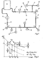
- the refueling system of an airport shown schematically in FIG. 1, has a pipe network 10 laid in the ground from a multiplicity of branched pipelines 11 connected to one another. At the end of the pipelines 11, some of which are stub lines, hydrants 12 are connected. The aircraft are refueled by so-called servicers who take off the fuel at the hydrant 12, clean it, reduce it to tank pressure and then direct it into the aircraft tank.
- the pipe network 10 is supplied with fuel from at least one main pump 13 from an above-ground fuel tank 14. The main pump 13 also ensures the necessary excess pressure in the pipes 11 of the pipe network 10.
- the pipe network 10 can be divided by means of a remotely controllable gate valve 15 into individual pipe sections with a predetermined liquid volume V. In Fig. 1, the pipe network 10 can be divided into four pipe sections A to D. A pressure sensor 16 for pressure measurement is provided in each pipe section.
- a leak test is carried out once a day in a longer, mostly several-hour refueling break in which fuel is not withdrawn from the pipe network 10 because of the stationary airport traffic.
- the pressure in all the pipes 11 of the pipe network 10 is set to a first outlet pressure level Pa1 of, for example, 9 bar.
- all gate valves 15 are closed, so that four hermetically sealed pipe sections A to D with a sufficiently small liquid volume in relation to the measuring accuracy and the maximum leakage flow permitted, which can be different in the individual pipe sections A to D and in the example is 40 m 3 , arise.
- the sufficiently small volume of liquid can be estimated from equation (1) if one knows the measuring accuracy of the pressure sensors 16 used and then defines the default value Ap.
- the constant K contains the permissible leakage current and B is determined by the geometry of the pipe network and the type of liquid.
- a pressure change difference .DELTA.p is now formed from the pressure changes .DELTA.p 1 and .DELTA.p 2 detected in the two measurement intervals and compared with a preset value .DELTA.p v . If there is a leak, the escaping leakage current depends on the overpressure in the pipe section. The higher this is, the greater the leakage losses. Since there are generally turbulent flow conditions at the outlet, the amount of leakage is a function of the root of the pressure difference between the pressure in the pipe system and the ambient pressure. The time course of the pressure results from the sizes agree with those given for equations (1) and (2). Due to the output pressure dependency of the leakage current, there is a pressure change difference in any case if there is a leak.
- the default value ⁇ p v can therefore be made 0.
- the default value ⁇ p v is calculated as described at the beginning and is, for example with a maximum permissible leakage current specification of 10 I / h, a liquid volume in the pipe section A of 40 m 3 , a measuring interval time of 10 min as the reference time unit and 0.147 bar for the specified two output pressures. If the pressure change difference Ap is greater than this preset value Ap., It can be concluded with certainty that there is a leak in the pipe section A. This process can be repeated several times, which significantly increases the reliability of the information.
- Fig. 2 two pressure profiles in the pipe section A are shown as a function of time. With this pressure curve, the assumption is made that there is no leak in pipe section A and the pressure drop is caused exclusively by a temperature gradient between the ground and the liquid in pipe section A. It is assumed that there is no longer a linear pressure curve over time.
- the pressure change here pressure drop
- the leakage quantity L flowing out through this leak under the operating condition of the pipe network 10 in the same time period of the measurement intervals, for example 10 minutes can be estimated in accordance with the following equation (4) the time-normalized pressure change difference measured in the measuring interval is multiplied by the reciprocal of the difference between the square root pressure levels p a1 and p a2 and multiplied by a constant.
- the constant x is system-specific and depends on the operating pressure p B of the pipe network 10 pending and is determined according to equation (5) wherein the constant B is calculated according to equation (2) and V represents the closed volume of the pipe section A.
- the estimation error for the leak quantity flowing out at the reference time unit is between -37 and + 49%, which is quite sufficient for assessing the leak size and the measures to be taken afterwards.
- the estimation error is based on the fact that in equations (4) and (5) again a turbulent flow in the leak is assumed.
- equations (4) and (5) the actual leak quantity flowing out in the reference time unit is where u can assume values between 0.3 and 0.8 depending on the type of flow in the leak and 0.5 for turbulence.
- the measured time-standardized pressure change difference Ap is reduced by a factor a before it is compared with the preset value Ap or used to estimate the leakage quantity L escaping per unit of time.
- the factor a depends on the difference between the outlet pressure levels p a and p a2 and is calculated according to equation (7)
- the constant C can be determined empirically by measuring the pressure change differences Ap occurring at measuring intervals on the dense network of pipes or on the individual pipe sections at a multiplicity of differently set outlet pressure levels Pal and Pa2 .
- the time-normalized pressure change differences are then plotted as a linear function of the difference between the outlet pressure levels p a1 and Pa2 , and the constant C is determined therefrom as the slope of the straight line according to equation (8)
- the invention is not restricted to the exemplary embodiment described above.
- the specified values for the time and pressure intervals are not mandatory, but rather adapted to the local conditions of the pipe network and the type and amount of the liquid. It is also not mandatory to determine the pressure change difference by setting an initially high and then low outlet pressure level in successive measurement intervals. The reverse setting of the outlet pressure levels brings the same results.
- the invention is also not restricted to the determination of the pressure change difference in two or three measuring intervals and to only two stages of the initial pressure level. In this way, several different output pressure levels can be set in several measuring intervals. The choice of measuring intervals of the same length of time is also not mandatory.
- the pressure changes, the pressure change difference and the default value and the estimated leakage quantity must be standardized, i.e. refer to the same unit of time. Recorded pressure changes must then be divided by the duration of the individual measurement intervals and multiplied by the reference time unit. None changes in the process. The calculation of the default value and the estimation of the leakage amount are then carried out with the reference time unit. It is equivalent to determining the slope of the pressure curve at predetermined times in the measurement interval, that is to say determining the time differential of the pressure.
- the method according to the invention is not only suitable for leak testing of liquid-filled pipes or pipe networks, as represented by the refueling system described.
- the method can also be used to test empty pipes or pipes intended for gas or dust transport for leaks.
- the pipes or pipe networks - if necessary divided into pipe sections - must be filled with liquid and sealed at the end.
Landscapes
- Physics & Mathematics (AREA)
- General Physics & Mathematics (AREA)
- Examining Or Testing Airtightness (AREA)
Description
Die Erfindung betrifft ein Verfahren zur Leckprüfung von Rohren oder Rohrnetzen der im Oberbegriff des Anspruchs 1 angegebenen Art. Unter Rohren und Rohrnetzen werden hier alle Arten von unverzweigten und verzweigten Leitungen beliebigen Querschnitts verstanden, in welchen Gas, Flüssigkeiten oder Staubpartikel transportiert werden oder die hierfür bestimmt sind.The invention relates to a method for leak testing of pipes or pipe networks of the type specified in the preamble of claim 1. Pipes and pipe networks are understood here to mean all types of unbranched and branched lines of any cross section in which gas, liquids or dust particles are transported or which are intended for this are.
Bei einem bekannten Verfahren dieser Art zur Dichtigkeitsprüfung von Pipelines wird die Dichtigkeit eines Rohrsystems in der Weise überprüft, dass der zu überprüfende Rohrabschnitt mit einer Flüssigkeit gefüllt und unter Druck gesetzt wird. Tritt infolge eines Lecks Flüssigkeit aus, dann sinkt der im Rohr herrschende Überdruck im Laufe der Zeit ab. Aus dem Druckabfall je Zeiteinheit und den bekannten Daten von Rohrsystem und Flüssigkeit kann dann auf das Vorhandensein und die Grösse eines Lecks geschlossen werden. ("Das DD-Differenz-Druck-Verfahren zur Dichtigkeitskontrolle von im Boden verlegten Rohöl-Fernleitungen", Schweizer Archiv, April 1963, S. 131-139.)In a known method of this type for leak testing pipelines, the tightness of a pipe system is checked in such a way that the pipe section to be checked is filled with a liquid and pressurized. If liquid leaks as a result of a leak, the overpressure in the pipe will decrease over time. The presence and size of a leak can then be concluded from the pressure drop per unit of time and the known data of the pipe system and liquid. ( " The DD differential pressure method for checking the tightness of crude oil pipelines laid in the ground", Swiss Archives, April 1963, pp. 131-139.)
Die Druckprobe wird erschwert durch die Tatsache, dass Druckänderungen auch ohne ein Leck dann auftreten, wenn Rohrinhalt und Rohrumgebung, z.B. Erdreich, sich nicht auf gleicher Temperatur befinden. Durch die zwischen Rohrinhalt und Rohrumgebung stattfindenden Temperaturausgleichsvorgänge steigt oder fällt der Druck im Leitungssystem bzw. im betreffenden Rohrabschnitt. Dies ist z.B. auf Flughäfen der Fall, wo der Treibstoff in Tanks gelagert wird und über ein unterirdisches Rohrnetz von einigen Kilometern Rohrlänge auf Zapfstellen verteilt wird. Durch Tankvorgänge gelangt ständig Treibstoff mit Tanktemperatur in das im Sommer relativ kühlere und im Winter wärmere Rohrsystem. Dazu kommt, dass Treibstoffmengen in den einzelnen Rohrabschnitten je nach der Vorgeschichte der Tankvorgänge unterschiedlich lange lagern und demzufolge sich mehr oder weniger an die Temperatur des umgebenden Erdreichs angleichen können. Wie in der genannten Literaturstelle gezeigt wird, bewirkt eine Temperaturänderung von nur 0,1 ° K in Rohölleitungen eine Druckänderung von 1 bar unabhängig vom Rauminhalt des Rohrnetzes. Andererseits tritt derselbe Druckabfall z.B. in einem 100 m3 enthaltenden Rohrabschnitt dann auf, wenn ca.101 ausgelaufen sind. Will man nun Leckstellen feststellen, die kleiner oder gleich 10 I/h sind, dann muss man entwe- der sicherstellen, dass sich die Temperatur im Rohrabschnitt um sehr viel weniger als 0,1 ° K/h ändert, oder man muss die mittlere Temperatur in dem Rohrabschnitt sehr genau ermitteln und die durch sie verursachte Druckschwankung rechnerisch korrigieren. Im ersten Fall kann man einen Temperaturausgleich durch Abwarten - typisch 3 d - erzwingen, da dann die Temperatur aufgrund der thermostatischen Eigenschaften des Erdbodens hinreichend konstant bleibt. Im zweiten Falle ist in jedem Falle eine hinreichende Dichte von Messstellen entlang der Rohrleitungen erforderlich. Schliesslich ist auch die Kombination beider Methoden anwendbar.The pressure test is made more difficult by the fact that pressure changes occur even without a leak if the pipe contents and pipe environment, eg soil, are not at the same temperature. Due to the temperature equalization processes taking place between the pipe contents and the pipe environment, the pressure in the pipe system or in the pipe section concerned rises or falls. This is the case, for example, at airports, where the fuel is stored in tanks and is distributed to taps via an underground pipe network with a pipe length of a few kilometers. Fueling processes constantly bring fuel with tank temperature into the pipe system, which is relatively cooler in summer and warmer in winter. In addition, the amounts of fuel in the individual pipe sections are stored for different lengths of time depending on the history of the fueling process and can therefore more or less adapt to the temperature of the surrounding soil. As is shown in the cited literature reference, a temperature change of only 0.1 ° K in crude oil lines causes a pressure change of 1 bar regardless of the volume of the pipe network. On the other hand, the same pressure drop occurs, for example, in a pipe section containing 100 m 3 when approx. 101 have leaked. If one wants to find leaks / are less than or equal to 10 I h, then you have to entwe - the make sure the temperature that the pipe section to be much less than 0.1 ° K / changes h, or you have the mean temperature Determine very precisely in the pipe section and correct the pressure fluctuation caused by them. In the first case, you can force a temperature equalization by waiting - typically 3 d - because then the temperature remains sufficiently constant due to the thermostatic properties of the soil. In the second case, a sufficient density of measuring points along the pipelines is required. Finally, the combination of both methods can also be used.
Bei einem Betankungssystem eines Flughafens sind jedoch mehrtägige Stillegungen auch nur von Teilen des Rohrnetzes nicht erträglich. Auch würden die Installation und der Betrieb eines hinreichend dichten und genauen Netzes von Temperaturmessstellen einen hohen Aufwand bedeuten.In the case of an airport fueling system, however, shutdowns lasting several days are not tolerable, even for parts of the pipe network. The installation and operation of a sufficiently dense and accurate network of temperature measuring points would also be very expensive.
Bei einem bekannten Verfahren zur Lecküberwachung von Rohrleitungen für den Transport gasförmiger Stoffe (DE-A-2741546) wird während der Förderung und der Förderpause der Rohrleitungsdruck überwacht und in festen Zeitabständen der Rohrleitungsdruck gemessen. Von den aufeinanderfolgenden Messwerten wird jeweils der Differenzwert gebildet. Jeder Differenzwert wird mit einer vorgegebenen zulässigen Abweichung verglichen. Bei Überschreitung der zulässigen Abweichungen in ununterbrochener Folge der Differenzwerte werden letztere gespeichert. Auf Leck wird dann erkannt, wenn mehr als z.B. drei unmittelbar aufeinanderfolgende Speicherwerte auftreten. Soweit dieses quasistatistische Verfahren für eine zuverlässige Lecküberwachung überhaupt geeignet ist, ist es höchstens in Gasversorgungssystemen einsetzbar.In a known method for leak monitoring of pipelines for the transport of gaseous substances (DE-A-2741546), the pipeline pressure is monitored during the conveying and the conveying pause and the pipeline pressure is measured at fixed intervals. The difference value is formed from the successive measured values. Each difference value is compared with a predetermined permissible deviation. If the permissible deviations are continuously exceeded, the difference values are saved. A leak is detected if more than e.g. three immediately consecutive memory values occur. As far as this quasi-statistical method is suitable for reliable leak monitoring, it can only be used in gas supply systems.
Der Erfindung liegt die Aufgabe zugrunde, ein Verfahren der eingangs genannten Art zu schaffen, mit welchem bei geringem technischen Aufwand Lecks - auch solche mit relativ geringer Grösse - in kurzer Zeit auch dann sicher und zuverlässig erfasst werden können, wenn sich die Temperatur des Rohrinhalts selbst während des Prüfvorgangs ändert.The invention has for its object to provide a method of the type mentioned, with which with little technical effort leaks - even those of relatively small size - can be detected safely and reliably in a short time even if the temperature of the pipe contents itself changes during the test process.
Die Aufgabe ist bei einem Verfahren zur Lecküberwachung der im Oberbegriff des Anspruchs 1 definierten Gattung erfindungsgemäss durch die Merkmale im Kennzeichnungsteil des Anspruchs 1 gelöst.The object is achieved according to the invention in a method for leak monitoring of the type defined in the preamble of claim 1 by the features in the characterizing part of claim 1.
Mitdem erfindungsgemässen Verfahren können selbst kleine Leckströme von etwa 1 I/h erkannt werden. Voraussetzung hierfür sind lediglich geeignete Drucksensoren, die eine ausreichende Reproduziergenauigkeit relativ zu dem maximalen Überdruck im Rohrnetz aufweisen, und ein hinreichend kleines Absperrvolumen. Handelsübliche Drucksensoren mit 0,1% Reproduziergenauigkeit bei 10 bar maximalem Überdruck genügen hierfür bereits. Für jedes Messintervall ist dabei eine Zeitdauer von grössenordnungsmässig 10 min ausreichend.With the method according to the invention, even small leakage currents of approximately 1 l / h can be recognized. The only prerequisite for this are suitable pressure sensors, which have sufficient reproducibility relative to the maximum overpressure in the pipe network, and a sufficiently small shut-off volume. Commercial pressure sensors with 0.1% reproducibility at 10 bar maximum overpressure are already sufficient for this. For each measuring interval, a period of the order of 10 minutes is sufficient.
Das erfindungsgemässe Verfahren ist temperaturunabhängig, so dass weder der bisher erforderliche immense Aufwand für ein umfangreiches Messstellennetz zur Temperaturmessung im Rohrsystem erforderlich ist, noch lange Wartezeiten für den Temperaturausgleich zwischen Rohrinhalt und Rohrumgebung in Kauf genommen werden müssen. Im Gegensatz zu leckbedingten Druckänderungen sind temperaturbedingte Drückänderungen praktisch nicht von den Ausgangsdruckniveaus im Rohrabschnitt abhängig. Da bei dem erfindungsgemässen Verfahren die Differenz der zeitnormierten Druckabfälle bei zwei verschiedenen Ausgangsdruckniveaus gebildet wird, heben sich die temperaturbedingten Anteile weitgehend heraus. Dies führt so lange zu absolut zuverlässigen Ergebnissen, als die Messzeit, d.h. die Summe der Zeitdauer der vorzugsweise unmittelbar aufeinanderfolgenden Messintervalle, sehr klein gegenüber der Halbwertzeit eines Temperaturausgleichsvorgangs zwischen dem Rohrinneren und -äusseren ist und somit für die Messzeit ein quasilinearer temperaturbedingter Druckverlauf besteht.The method according to the invention is temperature-independent, so that neither the immense effort previously required for an extensive measuring point network for temperature measurement in the pipe system nor long waiting times for the temperature compensation between pipe content and pipe environment have to be accepted. In contrast to leakage-related pressure changes, temperature-related pressure changes are practically not dependent on the outlet pressure levels in the pipe section. Since the difference between the time-standardized pressure drops is formed at two different output pressure levels in the method according to the invention, lift the temperature-related parts largely emerge. This leads to absolutely reliable results as long as the measurement time, i.e. the sum of the duration of the measurement intervals, which are preferably immediately following one another, is very short compared to the half-life of a temperature compensation process between the inside and the outside of the pipe, and thus there is a quasi-linear pressure curve for the measurement time.
Kann diese Annahme nicht mit ausreichender Sicherheit getroffen werden, z.B. weil aufgrund eines sehr kleinen zugelassenen maximalen Leckstroms, eines grossen Flüssigkeitsvolumens oder einer geringen Messgenauigkeit der Drucksensoren die Zeitdauer der Messintervalle relativ gross gewählt werden muss, so lässt sich die Zuverlässigkeit des erfindungsgemässen Verfahrens durch die weitere Ausgestaltung gemäss Anspruch 5 steigern. Durch diese Massnahmen wird die Druckänderung bei unterschiedlichen Ausgangsdruckniveaus quasi in dem gleichen Messintervall mit gleichen Zeitgrenzen erfasst und damit der Einfluss von Temperaturänderungen auf den Druckverlauf nahezu vollständig eliminiert. Da die Änderung des Ausgangsdruckniveaus und die Erfassung der jeweils zugeordneten Druckänderung praktisch jedoch nur zeitlich nacheinander - und nicht gleichzeitig - vorgenommen werden können, wird die Druckänderungserfassung für das eine Ausgangsdruckniveau einmal zeitlich vor und einmal zeitlich nach der Druckänderungserfassung für das andere Ausgangsdruckniveau durchgeführt und auf den Zeitraum der Druckänderungserfassung für das letztgenannte Ausgangsdruckniveau umgerechnet, so dass die Druckänderungen für beide Ausgangsdruckniveaus "pseudo-gleichzeitig" erfasst werden.If this assumption cannot be made with sufficient certainty, e.g. because the duration of the measuring intervals must be chosen to be relatively long due to a very small maximum leakage current, a large volume of liquid or a low measuring accuracy of the pressure sensors, the reliability of the method according to the invention can be determined by the further Increase design according to claim 5. These measures measure the pressure change at different outlet pressure levels in the same measuring interval with the same time limits and thus almost completely eliminate the influence of temperature changes on the pressure curve. However, since the change in the outlet pressure level and the detection of the respectively associated pressure change can practically only be carried out in succession - and not simultaneously - the pressure change detection for one outlet pressure level is carried out once before and once after the pressure change detection for the other outlet pressure level and on the The period of the pressure change detection for the last-mentioned outlet pressure level is converted so that the pressure changes for both outlet pressure levels are recorded " pseudo-simultaneously".
Eine vorteilhafte Ausgestaltung des erfindungsgemässen Verfahrens ergibt sich aus Anspruch 2. Durch die Vorgabe konstanter Messintervalle wird die Normierung der Druckänderungen auf eine Bezugszeiteinheit überflüssig und die Auswertung erleichtert.An advantageous embodiment of the method according to the invention results from
Eine vorteilhafte Ausgestaltung des erfindungsgemässen Verfahrens ergibt sich auch aus Anspruch 3. Durch die vorgesehene Regressionsrechnung kann bei überlagerten statistischen Schwankungen des Druckverlaufs und/oder der Messwertanzeige eine Druckänderung ermittelt werden, die zu brauchbaren Ergebnissen für die Leckprüfung und -erkennung führt.An advantageous embodiment of the method according to the invention also results from claim 3. The regression calculation provided can be used to determine a pressure change in the case of superimposed statistical fluctuations in the pressure curve and / or the measured value display, which leads to usable results for leak testing and detection.
Eine vorteilhafte Ausgestaltung des erfindungsgemässen Verfahrens ergibt sich aus Anspruch 6. Durch diese Festlegung des Vorgabewertes werden selbst die bei der Näherungsrechnung gemäss Anspruch 5 verbleibenden Restfehler eliminiert und können eine Fehlerkennung nicht hervorrufen. Der Vorgabewert Δpv lässt sich aus den Gesetzmässigkeiten im Leckkanal berechnen. Liegen turbulente Strömungsverhältnisse im Leckkanal vor, so ist die je Zeiteinheit auslaufende Flüssigkeitsmenge proportional zur Wurzel der Druckdifferenz zwischen Rohrinnerem und -äusserem, und der Vorgabewert berechnet sich ausAn advantageous embodiment of the method according to the invention results from claim 6. By this specification of the default value, even the residual errors remaining in the approximation calculation according to claim 5 are eliminated and cannot cause an error detection. The default value Δp v can be calculated from the regularities in the leakage channel. If there are turbulent flow conditions in the leakage channel, the amount of liquid flowing out per unit of time is proportional to the root of the pressure difference between the inside and the outside of the pipe, and the default value is calculated
![]()
![]()
Die Konstante B ist eine von der Geometrie des Rohrnetzes abhängige Grösse und wird berechnet nach![]()
![]()
Dabei sind:
- D der Durchmesser der Rohrleitung,
- d die Wanddicke der Rohrleitung,
- E der Elastizitätsmodul des Rohrwerkstoffes,
- b die Kompressibilität der im Rohrnetz enthaltenen Flüssigkeit.
- D the diameter of the pipeline,
- d the wall thickness of the pipeline,
- E the modulus of elasticity of the pipe material,
- b the compressibility of the liquid contained in the pipe network.
Bei einem Flüssigkeitsvolumen von V = 40 m3, einem zulässigen Leckstrom von 10 I/h, einem ersten Ausgangsdruckniveau von pa1 = 9 bar und einem zweiten Ausgangsdruckniveau von pa2 = 3 bar, einer Zeitdauer der Messintervalle von t = 10 min und einem Wert von B = 1,19·10-4 bar-1 ergibt sich ein Vorgabewert Δpv = 0,147 bar.With a liquid volume of V = 40 m 3 , a permissible leakage flow of 10 I / h, a first outlet pressure level of p a1 = 9 bar and a second outlet pressure level of p a2 = 3 bar, a duration of the measuring intervals of t = 10 min and one A value of B = 1.19 · 10 -4 bar -1 results in a default value Δp v = 0.147 bar.
Allgemein-d.h. ohne Festlegung aufturbulente Strömungen - lässt sich Gleichung (1) mit 

Kenntnis von der Art der Flüssigkeitsströmung im Leck ist nur erforderlich, wenn Lecks vorgegebener Grösse innerhalb nur geringer Toleranzen erfasst werden sollen. Ansonsten genügt die Annahme turbulenter Strömung vollständig. Der hierbei gemachte Fehler lässt sich berechnen zu![]()
![]()
Bei den vorstehend getroffenen Annahmen für pv, pa1 und Pa2 ergibt sich dabei für Δpv ein Fehler von -34 und +47%, d.h. es werden u.U. nicht nur Lecks mit Leckverlusten von grösser 10 I/h, sondern nur solche mit Leckverlusten von grösser 15 I/h (u = 0,3) oder sogar Lecks mit Leckverlusten ab ≈ 7 I/h (u = 0,8) erfasst.With the assumptions made above for p v , p a1 and Pa2 , there is an error of -34 and + 47% for Δp v , ie there may not only be leaks with leakage losses of greater than 10 I / h, but only those with leakage losses of bigger 15 I / h (u = 0.3) or even leaks with leakage losses from ≈ 7 I / h (u = 0.8) are recorded.
Eine vorteilhafte Ausgestaltung des erfindungsgemässen Verfahrens ergibt sich auch aus Anspruch 7. Wird der Vorgabewert annähernd 0 gesetzt, so können selbst kleinste Leckströme sicher erkannt werden. Voraussetzung für die Zuverlässigkeit dieses Vorgabewertes und damit für die Vermeidung einer hohen Falschalarmrate ist jedoch einerseits, dass temperaturbedingte zeitliche Druckänderungen konstant sind, der temperaturbedingte Druckverlauf also absolut linear ist, und andererseits die Ausschaltung von Messungenauigkeiten.An advantageous embodiment of the method according to the invention also results from claim 7. If the default value is set to approximately 0, even the smallest leakage currents can be reliably detected. A prerequisite for the reliability of this default value and thus for avoiding a high false alarm rate is, on the one hand, that temperature-related temporal pressure changes are constant, that is, the temperature-related pressure curve is absolutely linear, and, on the other hand, the elimination of measurement inaccuracies.
Eine weitere vorteilhafte Ausgestaltung des erfindungsgemässen Verfahrens ergibt sich aus Anspruch 8, auch in Verbindung mit Anspruch 9. Durch diese Massnahmen kann bei Leckfeststellung die unter Betriebsbedingungen im Rohrsystem oder Rohrabschnitt auslaufende Leckmenge pro Zeiteinheit abgeschätzt werden. Dadurch können sichere und ausgewogene Entscheidungen bezüglich der Weiterführung oder Stillegung des Rohrsystems getroffen werden. Z.B. ergibt die Kenntnis von der Grösse des Lecks Entscheidungshilfen, einen Rohrabschnitt abzuschotten oder sofort auszupumpen, weil das Leck zu gross ist. Andererseits kann das detektierte Leck wegen der ausfliessenden kleinen Leckmenge nur zur Kenntnis genommen und durch Anwendung entsprechender Rechnung auf den Leckstrom Trends im Verhalten des Lecks erkannt werden.A further advantageous embodiment of the method according to the invention results from claim 8, also in conjunction with claim 9. By means of these measures, the leak amount per unit time under operating conditions in the pipe system or pipe section can be estimated when a leak is detected. This enables safe and balanced decisions to be made regarding the continuation or decommissioning of the pipe system. E.g. Knowing the size of the leak gives decision aids to seal off a pipe section or to pump it out immediately because the leak is too large. On the other hand, the detected leak can only be noted due to the small leakage amount flowing out, and trends in the behavior of the leak can be identified by applying an appropriate calculation to the leakage current.
Eine vorteilhafte Ausgestaltung des erfindungsgemässen Verfahrens ergibt sich aus Anspruch 10, insbesondere in Verbindung mit Anspruch 11. Durch diese Massnahmen werden bei vergrabenen Rohren oder Rohrnetzen in der Praxis beobachtete sog. Kriechvorgänge, die sich verfälschend bei der Messung der Druckänderungen auswirken, rechnerisch kompensiert. Solche Kriechvorgänge machen sich bei Druckänderungen im temperaturstabilen Rohr oder Rohrnetz dadurch bemerkbar, dass sich zunächst ein höherer (Druckerhöhung) bzw. ein niedrigerer (Druckerniedrigung) Druck als vorgegeben einstellt, der nachfolgend mit einer Zeitkonstante von etwa 0,5-1 h wieder abfällt bzw. ansteigt und dann konstant bleibt.An advantageous embodiment of the method according to the invention results from
Die Kompensation der Kriechvorgänge erlaubt einerseits eine Reduzierung der Falschalarmrate und eine genauere Schätzung der pro Zeiteinheit ausfliessenden Leckmenge und andererseits Messungen in nur kurzen Zeitabständen, wobei die Messphasen bereits einige Minuten nach der Einstellung des jeweiligen Ausgangsdruckniveaus beginnen können und die Abstände der Einstellungen voneinander, die sog. Messintervalle, nicht grösser als 10 min zu sein brauchen.The compensation of the creeping processes allows, on the one hand, a reduction in the false alarm rate and a more precise estimate of the leakage amount flowing out per unit of time, and, on the other hand, measurements in only short time intervals, whereby the measurement phases can begin a few minutes after the setting of the respective output pressure level and the distances between the settings, the so-called Measurement intervals need not be longer than 10 min.
Die Konstante C, mit welcher die Differenz der Ausgangsdruckniveaus zu multiplizieren ist, ist rohrnetzspezifisch und lässt sich entsprechend einer weiteren Ausgestaltung der Erfindung gemäss Anspruch 12 mit den dort angegebenen Verfahrensschritten empirisch bestimmen. Versuche haben ergeben, dass die Konstante C weitgehend unabhängig von der Rohrnetz- und Rohrgestaltung ist, doch in gewissem Masse von der Struktur des das Rohrnetz umgebenden Erdreichs abhängig ist. Für ein in Sand eingebettetes Rohrsystem wurde die Konstante C zu 16. 10-6 S-1 bestimmt.The constant C, by which the difference in the outlet pressure levels is to be multiplied, is specific to the pipe network and can be determined empirically in accordance with a further embodiment of the invention according to claim 12 with the method steps specified therein. Tests have shown that the constant C is largely independent of the pipe network and pipe design, but is to a certain extent dependent on the structure of the soil surrounding the pipe network. For a pipe system embedded in sand, the constant C was determined to be 16. 10-6 S - 1 .
Die Erfindung ist anhand einesAusführungsbeispiels der Lecküberwachung eines Flugzeugbetankungssystems auf einem Flughafen unter Bezugnahme auf die Zeichnung im folgenden näher beschrieben. Es zeigen:
- Fig. 1 eine schematische Darstellung eines Betankungssystems eines Flughafens,
- Fig. 2 ein Diagramm eines angenommenen temperaturbedingten zeitlichen Druckverlaufs in einem abgeschlossenen Rohrabschnitt mit konstantem Flüssigkeitsvolumen.
- 1 is a schematic representation of an airport fueling system,
- Fig. 2 is a diagram of an assumed temperature-related temporal pressure curve in a closed pipe section with a constant liquid volume.
Das in Fig. 1 schematisch dargestellte Betankungssystem eines Flughafens weist ein im Erdboden verlegtes Rohrnetz 10 aus einer Vielzahl von miteinander verbundenen verzweigten Rohrleitungen 11 auf. Am Ende der Rohrleitungen 11, die teilweise als Stichleitungen ausgeführt sind, sind Hydranten 12 angeschlossen. Die Betankung der Flugzeuge erfolgt über sog. Servicer, die den Treibstoff an den Hydranten 12 abnehmen, feinreinigen, auf Tankdruck reduzieren und anschliessend in den Flugzeugtank leiten. Das Rohrnetz 10 wird über mindestens eine Hauptpumpe 13 aus einem oberirdischen Treibstofftank 14 mit Treibstoff versorgt. Die Hauptpumpe 13 stellt auch den nötigen Überdruck in den Rohrleitungen 11 des Rohrnetzes 10 sicher. Das Rohrnetz 10 kann mittels fernsteuerbarer Absperrschieber 15 in einzelne Rohrabschnitte mit vorgegebenen Flüssigkeitsvolumen V unterteilt werden. In Fig. 1 ist das Rohrnetz 10 in vier Rohrabschnitte A bis D unterteilbar. In jedem Rohrabschnitt ist ein Drucksensor 16 zur Druckmessung vorgesehen.The refueling system of an airport, shown schematically in FIG. 1, has a
Eine Leckprüfung erfolgt einmal am Tage in einer längeren, meist mehrstündigen Tankpause, in welcher eine Treibstoffentnahme aus dem Rohrnetz 10 wegen des ruhenden Flughafenverkehrs nicht stattfindet. Mittels der Hauptpumpe 13 wird bei geöffneten Absperrschiebern 15 der Druck in allen Rohrleitungen 11 des Rohrnetzes 10 auf ein erstes Ausgangsdruckniveau Pa1 von z.B. 9 bar eingestellt. Dann werden sämtliche Absperrschieber 15 geschlossen, so dass vier hermetisch abgeschlossene Rohrabschnitte A bis D mit einem im Verhältnis zur Messgenauigkeit und dem zugelassenen maximalen Leckstrom hinreichend kleinen Flüssigkeitsvolumen, das in den einzelnen Rohrabschnitten A bis D unterschiedlich sein kann und im Beispiel 40 m3 beträgt, entstehen. Das hinreichend kleine Flüssigkeitsvolumen lässt sich anhand der Gleichung (1 ) abschätzen, wenn man die Messgenauigkeitderverwendeten Drucksensoren 16 kennt und hiernach den Vorgabewert Ap, festlegt. Die Konstante K enthält den zulässigen Leckstrom und B ist durch die Geometrie des Rohrnetzes und der Art der Flüssigkeit bestimmt.A leak test is carried out once a day in a longer, mostly several-hour refueling break in which fuel is not withdrawn from the
In jedem Rohrabschnitt A bis D wird nunmehr eine Leckprüfung durchgeführt, die anhand der Leckprüfung des Rohrabschnittes A im folgenden beschrieben wird.A leak test is now carried out in each pipe section A to D, which is described below with reference to the leak test of pipe section A.
In einem ersten Messintervall mit einerZeitdauer von z. B. 10 min wird die Druckänderung Δp1 mittels des Drucksensors 16, ausgehend von dem ersten Ausgangsdruckniveau pa1 = 9 bar, gemessen. Danach werden alle Absperrschieber 15 wieder geöffnet und der Druck in den Rohrabschnitten A bis D auf ein zweites Ausgangsdruckniveau pa2 von z.B. 3 bar abgesenkt, was durch gesteuertes Öffnen eines weiteren Absperrschiebers 17 erfolgen kann. Ist der Druck im Rohrnetz 10 3 bar, so werden wiederum alle Absperrschieber 15 geschlossen. Nunmehr wird in dem Rohrabschnitt A in einem zweiten Messintervall gleicher Dauer von 10 min die Druckänderung Δp2, ausgehend von dem zweiten Ausgangsdruckniveau pa2 = 3 bar, mittels des Drucksensors 16 gemessen.In a first measurement interval with a period of e.g. B. 10 min, the pressure change Δp 1 is measured by means of the
Aus den in den beiden Messintervallen erfassten Druckänderungen Δp1 und Δp2 wird nunmehr eine Druckänderungsdifferenz Δp gebildet und mit einem Vorgabewert Δpv verglichen. Ist ein Leck vorhanden, so ist der austretende Leckstrom vom Überdruck im Rohrabschnitt abhängig. Je höher dieser ist, desto grössere Leckverluste entstehen. Da beim Ausströmen im allgemeinen turbulente Strömungsverhältnisse vorliegen, ist die Leckmenge eine Funktion der Wurzel der Druckdifferenzzwischen dem Druck im Rohrsystem und dem Umgebungsdruck. Der zeitliche Verlauf des Drucks ergibt sich aus![]()
![]()
Zur Verbesserung der Druckänderungserfassung im Hinblick auf Ausschaltung statistischer Schwankungen des Drucks oder der Messwertanzeige ist es auch möglich, in jedem Messintervall mehrere Druckmessungen vorzunehmen und die Druckänderung im Messintervall durch eine Ausgleichs- oder Regressionsrechnung aus den Druckwerten zu gewinnen.To improve the detection of pressure changes with a view to eliminating statistical fluctuations in pressure or the display of measured values, it is also possible to carry out several pressure measurements in each measuring interval and to obtain the pressure change in the measuring interval by means of a compensation or regression calculation from the pressure values.
Das vorstehend beschriebene Messverfahren ist ausreichend, wenn davon ausgegangen werden kann, dass temperaturbedingte Druckänderungen im wesentlichen konstant sind, der durch ein Temperaturgefälle hervorgerufene Druckverlauf als Funktion der Zeit in etwa linear ist. Selbst grössere Abweichungen von der Linearität führen zu keiner Verfälschung des Ergebnisses, da der Vorgabewert aufgrund eines relativ hohen zugelassenen Leckstroms gross ist. Wird der zu gelassene maximale Leckstrom wesentlich verkleinert, z.B. mit 1 I/h vorgegeben, so ist es zweckmässig, auch temperaturbedingte Druckänderungen besser zu kompensieren. Ebenso muss dann auch die geringe, im Prinzip bekannte Druckabhängigkeit der Grösse b in Gleichung (2) berücksichtigt werden.The measuring method described above is sufficient if it can be assumed that temperature-related pressure changes are essentially constant, the pressure curve caused by a temperature gradient being approximately linear as a function of time. Even larger deviations from the linearity do not falsify the result, since the default value is large due to a relatively high permitted leakage current. If the permitted maximum leakage current is significantly reduced, e.g. with 1 I / h, it is advisable to better compensate for temperature-related changes in pressure. Likewise, the small, in principle known pressure dependence of quantity b in equation (2) must also be taken into account.
In Fig. 2 sind beispielhaft zwei Druckverläufe im Rohrabschnitt A als Funktion der Zeit dargestellt. Bei diesem Druckverlauf ist die Annahme getroffen, dass kein Leck im Rohrabschnitt A vorhanden ist und der Druckabfall ausschliesslich durch ein Temperaturgefälle zwischen dem Erdboden und der Flüssigkeit im Rohrabschnitt A hervorgerufen wird. Dabei ist davon ausgegangen, dass ein linearer Druckverlauf über der Zeit nicht mehr gegeben ist. In diesem Fall wird, wie vorstehend bereits beschrieben, die Druckänderung, hier Druckabfall, in einem ersten Messintervall zwischen der Zeit to und t, (10 min) bei einem Ausgangsdruckniveau pa1 = 9 bar, der Druckabfall in einem zweiten Messintervall zwischen den Zeitgrenzen t1 und t2 (10 min) bei einem Ausgangsdruckniveau von pa2 = 3 bar und der Druckabfall in einem dritten Messintervall mit den Zeitgrenzen t2 und t3 (10 min) mit einem Ausgangsdruckniveau wiederum pa1 = 9 bar gemessen. Aus den im ersten und dritten Messintervall bestimmten Druckabfällen Δp1 und Δp3 (Fig. 2) wird nunmehr durch Näherungsrechnung, z.B. durch Interpolation, ein Druckabfall im zweiten Messintervall mit den Zeitgrenzen t1 und t2 und einem Ausgangsdruckniveau von pa1 = 9 bar ermittelt. Aus diesem so berechneten "Pseudo-Druckabfall" Δp'2 im zweiten Messintervall mit dem Ausgangsdruckniveau pa1 = 9 bar und dem im zweiten Messintervall gemessenen Druckabfall AP2 bei einem Ausgangsdruckniveau pa2 = 3 bar wird nunmehr die Druckabfalldifferenz Ap berechnet. Ist kein Leck im Rohrabschnitt A vorhanden, so müsste diese Differenz in etwa 0 sein, in jedem Fall ist sie aber wesentlich kleiner als der Vorgabewert Apv.In Fig. 2 two pressure profiles in the pipe section A are shown as a function of time. With this pressure curve, the assumption is made that there is no leak in pipe section A and the pressure drop is caused exclusively by a temperature gradient between the ground and the liquid in pipe section A. It is assumed that there is no longer a linear pressure curve over time. In this case, as already described above, the pressure change, here pressure drop, in a first measurement interval between the time t o and t (10 min) at an initial pressure level p a1 = 9 bar, the pressure drop in a second measurement interval between the time limits t 1 and t 2 (10 min) at an outlet pressure level of p a2 = 3 bar and the pressure drop in a third measuring interval with the time limits t 2 and t 3 (10 min) again at an outlet pressure level p a1 = 9 bar. From the pressure drops Δ p1 and Δ p3 (FIG. 2) determined in the first and third measurement interval, a pressure drop in the second measurement interval with the time limits t 1 and t 2 and an output pressure level of p a1 = 9 bar is now made by approximation, for example by interpolation determined. From this " pseudo pressure drop" Δp ' 2 calculated in this way in the second measuring interval with the initial pressure level p a1 = 9 bar and the pressure drop A P2 measured in the second measuring interval at an initial pressure level p a2 = 3 bar, the pressure drop difference Ap is now calculated. If there is no leak in pipe section A, this difference should be approximately 0, but in any case it is significantly smaller than the default value Ap v .
Ist ein Leck im Rohrabschnitt A nachgewiesen, so kann die unter Betriebsbedingung des Rohrnetzes 10 durch dieses Leck in der gleichen Zeitdauer der Messintervalle, z.B. 10 min ausströmende Leckmenge L grössenordnungsmässig abgeschätzt werden, indem man gemäss nachfolgender Gleichung (4)![]()
![]()
![]()
![]()
Mit den eingangs für ein Ausführungsbeispiel angegebenen Werten und einem Betriebsdruck des Rohrnetzes 10 von 7 bar bestimmt sich die Konstante x nach Gleichung (5) zu![]()
![]()
Der Schätzungsfehler für die an der Bezugszeiteinheit ausfliessende Leckmenge liegt in dem Beispiel dabei zwischen -37 und +49%, was zur Beurteilung der Leckgrösse und der danach zu ergreifenden Massnahmen durchaus ausreichend ist. Der Schätzungsfehler beruht darauf, dass in Gleichungen (4) und (5) wiederum eine turbulente Strömung im Leck vorausgesetzt wird. Die tatsächliche, in der Bezugszeiteinheit ausfliessende Leckmenge beträgt mit Gleichungen (4) und (5)![]()
![]()
Bei Messungen hat sich gezeigt, dass bei vergrabenen Rohrnetzen Kriechvorgänge auftreten, die sich dadurch äussern, dass bei Einstellung des Ausgangsdruckniveaus, also bei Druckerhöhung bzw. Druckerniedrigung, in dem temperaturstabilen, d.h. mit der Umgebung temperaturausgeglichen, Rohrabschnitt zunächst sich ein gegenüber dem Ausgangsdruckniveau etwas erhöhter bzw. erniedrigter Druck einstellt, der dann mit einer Zeitkonstanten von etwa 0,5 bis 1 h abfällt bzw. ansteigt und dann konstant bleibt. Werden in dieser Zeit die Druckänderungsmessungen durchgeführt - was für die schnelle Durchführung der Leckprüfung angestrebt wird -, so wirken sich die Kriechvorgänge verfälschend auf das Messergebnisaus. Z.B. können diese Kriechvorgänge bei völlig dichtem Rohrabschnitt einen Leckstrom von 5-7 1/h vortäuschen. Um diese Vorgänge zu kompensieren, wird die gemessene zeitnormierte Druckänderungsdifferenz Ap noch um einen Faktor a reduziert, bevor sie mit dem Vorgabewert Ap, verglichen oder zur Schätzung der pro Zeiteinheit austretenden Leckmenge L herangezogen wird. Der Faktor a ist abhängig von der Differenz der Ausgangsdruckniveaus pa, und pa2 und berechnet sich nach Gleichung (7) zu![]()
![]()
Die Konstante C lässt sich empirisch bestimmen, indem an dem dichten Rohrnetz oder an den einzelnen Rohrabschnitten jeweils die in Messintervallen auftretenden Druckänderungsdifferenzen Ap bei einer Vielzahl von unterschiedlich eingestellten Ausgangsdruckniveaus Pal und Pa2 gemessen werden. Die zeitnormierten Druckänderungsdifferenzen werden dann als lineare Funktion der Differenz der Ausgangsdruckniveaus pa1 und Pa2 aufgetragen und daraus die Konstante C als Steigung der Geraden gemäss Gleichung (8) ermittelt![]()
![]()
Die Erfindung ist nicht auf das vorstehend beschriebene Ausführungsbeispiel beschränkt. So sind die angegebenen Werte für die Zeit- und Druckintervalle nicht zwingend, sondern vielmehr an die örtlichen Verhältnisse des Rohrnetzes und der Art und Menge der Flüssigkeit angepasst. Auch ist es nicht zwingend, die Druckänderungsdifferenz durch Einstellung eines zunächst hohen und dann niedrigen Ausgangsdruckniveaus in aufeinanderfolgenden Messintervallen zu bestimmen. Die umgekehrte Einstellung der Ausgangsdruckniveaus bringt gleiche Ergebnisse mit sich. Die Erfindung ist auch nicht auf die Bestimmung der Druckänderungsdifferenz in zwei oder drei Messintervallen und auf nur zwei Stufen des Ausgangsdruckniveaus beschränkt. So können in mehreren Messintervallen auch mehrere, voneinander verschiedene Ausgangsdruckniveaus eingestellt werden. Auch die Wahl von Messintervallen gleicher Zeitdauer ist nicht zwingend. Wird die Zeitdauer der einzelnen Messintervalle verschieden gewählt,so müssen die Druckänderungen, die Druckänderungsdifferenz und der Vorgabewert und die geschätzte Leckmenge normiert, d.h. auf die gleiche Zeiteinheit bezogen werden. Erfasste Druckänderungen müssen dann noch durch die Zeitdauer der einzelnen Messintervalle dividiert und mit der Bezugszeiteinheit multipliziert werden. An dem Verfahren ändert sich dabei nichts. Die Berechnung des Vorgabewertes und die Schätzung der Leckmenge erfolgt dann mit der Bezugszeiteinheit. Gleichbedeutend damit ist, die Steigung des Druckverlaufs zu vorgegebenen Zeitpunkten im Messintervall zu bestimmen, also das zeitliche Differential des Drucks zu bestimmen.The invention is not restricted to the exemplary embodiment described above. The specified values for the time and pressure intervals are not mandatory, but rather adapted to the local conditions of the pipe network and the type and amount of the liquid. It is also not mandatory to determine the pressure change difference by setting an initially high and then low outlet pressure level in successive measurement intervals. The reverse setting of the outlet pressure levels brings the same results. The invention is also not restricted to the determination of the pressure change difference in two or three measuring intervals and to only two stages of the initial pressure level. In this way, several different output pressure levels can be set in several measuring intervals. The choice of measuring intervals of the same length of time is also not mandatory. If the duration of the individual measurement intervals is selected differently, the pressure changes, the pressure change difference and the default value and the estimated leakage quantity must be standardized, i.e. refer to the same unit of time. Recorded pressure changes must then be divided by the duration of the individual measurement intervals and multiplied by the reference time unit. Nothing changes in the process. The calculation of the default value and the estimation of the leakage amount are then carried out with the reference time unit. It is equivalent to determining the slope of the pressure curve at predetermined times in the measurement interval, that is to say determining the time differential of the pressure.
Bei der Leckprüfung ist es auch möglich, dass als Druckänderung nicht ein Druckabfall, sondern ein Druckanstieg erfasst wird. Dies ist der Fall, wenn z.B. die Temperatur der Flüssigkeit zunächst kühler ist als die der Rohrumgebung. Aufgrund der bei einem Leck aber immer auftretenden Druckänderungsdifferenz zwischen den Druckänderungen bei zwei verschiedenen Ausgangsdruckniveaus wird das Leck sicher erkannt.In the leak test, it is also possible that not a drop in pressure but a rise in pressure is recorded as a change in pressure. This is the case if e.g. the temperature of the liquid is initially cooler than that of the pipe environment. Because of the pressure change difference that always occurs in the event of a leak between the pressure changes at two different outlet pressure levels, the leak is reliably detected.
Das erfindungsgemässe Verfahren ist nicht nur zur Leckprüfung von flüssigkeitsgefüllten Rohren oder Rohrnetzen, wie sie von dem beschriebenen Betankungssystem dargestellt werden, geeignet. Mit dem Verfahren können auch leere Rohre oder solche, die zum Gas- oder Staubtransport bestimmt sind, auf Leck geprüft werden. In diesem Fall sind die Rohre oder Rohrnetze - ggf. unter Unterteilung in Rohrabschnitte - mit Flüssigkeit zu füllen und endseitig zu verschliessen.The method according to the invention is not only suitable for leak testing of liquid-filled pipes or pipe networks, as represented by the refueling system described. The method can also be used to test empty pipes or pipes intended for gas or dust transport for leaks. In this case, the pipes or pipe networks - if necessary divided into pipe sections - must be filled with liquid and sealed at the end.
Claims (13)
Priority Applications (1)
| Application Number | Priority Date | Filing Date | Title |
|---|---|---|---|
| AT83104218T ATE18607T1 (en) | 1982-05-15 | 1983-04-29 | PROCEDURE FOR LEAK TESTING OF PIPES OR PIPE NETWORKS. |
Applications Claiming Priority (3)
| Application Number | Priority Date | Filing Date | Title |
|---|---|---|---|
| DE3218477 | 1982-05-15 | ||
| DE3218477 | 1982-05-15 | ||
| US06/547,096 US4608857A (en) | 1982-05-15 | 1983-10-31 | Method for checking pipes or pipe networks for leaks |
Publications (2)
| Publication Number | Publication Date |
|---|---|
| EP0094533A1 EP0094533A1 (en) | 1983-11-23 |
| EP0094533B1 true EP0094533B1 (en) | 1986-03-12 |
Family
ID=25801859
Family Applications (1)
| Application Number | Title | Priority Date | Filing Date |
|---|---|---|---|
| EP83104218A Expired EP0094533B1 (en) | 1982-05-15 | 1983-04-29 | Method for leakage testing of pipes or networks of pipes |
Country Status (3)
| Country | Link |
|---|---|
| US (1) | US4608857A (en) |
| EP (1) | EP0094533B1 (en) |
| DE (1) | DE3316849A1 (en) |
Families Citing this family (66)
| Publication number | Priority date | Publication date | Assignee | Title |
|---|---|---|---|---|
| EP0188911A3 (en) * | 1984-12-25 | 1987-09-16 | Nippon Kokan Kabushiki Kaisha | Method and apparatus for detecting leaks in a gas pipe line |
| US4715214A (en) * | 1986-10-03 | 1987-12-29 | S. Himmelstein And Company | Leak tester |
| AU603644B2 (en) * | 1987-01-16 | 1990-11-22 | Saipem Australia Pty. Limited | Testing of pipelines |
| GB8707231D0 (en) * | 1987-03-26 | 1987-04-29 | Analytical Instr Ltd | Temperature compensation in pressure leak detection |
| GB8716032D0 (en) * | 1987-07-08 | 1987-08-12 | British Telecomm | Duct testing |
| US4876530A (en) * | 1987-10-13 | 1989-10-24 | The Marley Company | Method and apparatus for detecting leakage in fuel storage and delivery systems |
| EP0426803B1 (en) * | 1989-05-19 | 1993-12-29 | KUNZE, Silvia | Leak detection for hydraulic drive systems |
| US5632269A (en) * | 1989-09-22 | 1997-05-27 | Respironics Inc. | Breathing gas delivery method and apparatus |
| DE3933265C2 (en) * | 1989-10-05 | 1993-11-04 | Walter Ludwig Behaelter Stahl | METHOD AND DEVICE FOR LEAK TESTING IN MULTI-WALLED PRESSURE TANKS |
| US5078006A (en) * | 1990-08-30 | 1992-01-07 | Vista Research, Inc. | Methods for detection of leaks in pressurized pipeline systems |
| US5375455A (en) * | 1990-08-30 | 1994-12-27 | Vista Research, Inc. | Methods for measuring flow rates to detect leaks |
| US5090234A (en) * | 1990-08-30 | 1992-02-25 | Vista Research, Inc. | Positive displacement pump apparatus and methods for detection of leaks in pressurized pipeline systems |
| US5317899A (en) * | 1992-12-11 | 1994-06-07 | Control Engineers, Inc. | Method for detecting leaks in underground product lines |
| GB9302958D0 (en) * | 1993-02-13 | 1993-03-31 | Lucas Ind Plc | Method of and apparatus for detecting fuel system leak |
| US5372032A (en) * | 1993-04-23 | 1994-12-13 | Filippi; Ernest A. | Pressurized piping line leak detector |
| US5361622A (en) * | 1993-09-09 | 1994-11-08 | The Shafer Valve Company | Device and method for detection of leaks in pressurized fluid vessels |
| US5377529A (en) * | 1993-11-15 | 1995-01-03 | Boyd; Mark A. | Leak detecting device, and method of constructing and utilizing same |
| US5450883A (en) * | 1994-02-07 | 1995-09-19 | Gilbarco, Inc. | System and method for testing for error conditions in a fuel vapor recovery system |
| GB9403184D0 (en) * | 1994-02-18 | 1994-04-06 | Boc Group Plc | Methods and apparatus for leak testing |
| US5557965A (en) * | 1994-10-20 | 1996-09-24 | Dover Corporation | Pipeline leak detector |
| US5526679A (en) * | 1995-01-05 | 1996-06-18 | Campo/Miller | Automatically calibrated pressurized piping leak detector |
| GB9505815D0 (en) * | 1995-03-22 | 1995-05-10 | British Gas Plc | Method of testing pipes for leakage |
| JP3543426B2 (en) * | 1995-07-06 | 2004-07-14 | 株式会社日立製作所 | Pipe network management method and system |
| DE19609071C2 (en) * | 1996-03-08 | 2000-05-18 | Wtw Weilheim | Procedure for avoiding errors when measuring or determining the gas consumption of matter |
| US6012482A (en) * | 1997-01-30 | 2000-01-11 | Djt Products, Inc. | Line break detector for pressurized fluid pumping systems |
| GB9711432D0 (en) * | 1997-06-04 | 1997-07-30 | British Gas Plc | Pipe leakage detection |
| US5948969A (en) * | 1997-10-20 | 1999-09-07 | Vista Research, Inc. | Methods for measuring the flow rate due to a leak in a pressurized pipe system |
| SE513838C2 (en) * | 1998-06-25 | 2000-11-13 | Gambro Lundia Ab | Method and apparatus for calibrating sensing means in a system with a flowing fluid |
| US6070452A (en) * | 1998-07-16 | 2000-06-06 | Brannan; Gene T. | Pipe leak locator with pressure gauge |
| WO2000020832A1 (en) * | 1998-10-07 | 2000-04-13 | Paavo Halmekytö Consulting Oy | Method for determination of leaks in tap water systems |
| US6244100B1 (en) * | 1999-01-29 | 2001-06-12 | Caldon, Inc. | Temperature compensation for automated leak detection |
| US6311548B1 (en) * | 1999-08-25 | 2001-11-06 | Delphi Technologies, Inc. | Method of validating a diagnostic leak detection test for a fuel tank |
| DE19957998C2 (en) * | 1999-12-02 | 2001-10-18 | Josef Messmann Gmbh | Method and device for checking porous pipes or the like for leaks |
| US6336479B1 (en) | 2000-02-07 | 2002-01-08 | Marconi Commerce Systems Inc. | Determining vapor recovery in a fueling system |
| EP1305588A4 (en) | 2000-05-02 | 2007-08-15 | Vista Res Inc | Improved methods for detecting leaks in pressurized piping with a pressure measurement system |
| AU2002365526A1 (en) * | 2001-11-27 | 2003-06-10 | Shinichiro Arima | Pressure measuring method and device |
| DE10201109C1 (en) * | 2002-01-15 | 2003-01-23 | Fresenius Medical Care De Gmbh | Detecting leak in liquid system of blood treatment system involves deriving leakage rate from change in pressure in defined intervals, driving leakage volume from leakage rate |
| DE10242162A1 (en) * | 2002-09-10 | 2004-03-18 | Cegelec Anlagen- Und Automatisierungstechnik Gmbh & Co. Kg | Pipeline leak detection method, especially for airfield fire-hydrant system, whereby trend curves are determined for pressure and temperature and combined for accurate determination of absolute volume alterations |
| FR2849695B1 (en) * | 2003-01-08 | 2005-06-03 | Michel Georges Andre Somnier | METHOD FOR CONTROLLING AND DIAGNOSING LEAKS ON A GAS DISTRIBUTION NETWORK |
| US7263873B2 (en) * | 2005-03-04 | 2007-09-04 | Robert Charles Richey | System and method for detecting leaks in pressurized piping systems |
| US7613584B2 (en) * | 2006-05-01 | 2009-11-03 | Hansa Consult Of North America, Llc | Methods, systems and computer program products for automatically detecting leaks in a hydrant fuel piping system |
| US8061360B2 (en) | 2006-09-19 | 2011-11-22 | Kci Licensing, Inc. | System and method for locating fluid leaks at a drape of a reduced pressure delivery system |
| US8366690B2 (en) * | 2006-09-19 | 2013-02-05 | Kci Licensing, Inc. | System and method for determining a fill status of a canister of fluid in a reduced pressure treatment system |
| US7438060B2 (en) * | 2006-11-17 | 2008-10-21 | General Motors Corporation | System for detecting purge valve malfunction |
| NO329802B1 (en) * | 2009-02-24 | 2010-12-20 | Vemund Eithun | System and method for leakage control and / or testing of piping and tapping points for non-compressible liquids |
| US9207143B2 (en) | 2009-08-18 | 2015-12-08 | Innovative Pressure Testing, Llc | System and method for determining leaks in a complex system |
| US10031042B2 (en) | 2009-08-18 | 2018-07-24 | Innovative Pressure Testing, Llc | System and method for detecting leaks |
| WO2011022132A2 (en) * | 2009-08-18 | 2011-02-24 | Franklin Charles M | System and method for detecting leaks |
| US8682600B2 (en) | 2011-07-06 | 2014-03-25 | Saudi Arabian Oil Company | Pipeline leak detection and location system through pressure and cathodic protection soil |
| CN103245466A (en) * | 2013-05-11 | 2013-08-14 | 中煤科工集团武汉设计研究院 | Pigging and pressure testing method for long distance pipeline coal transportation |
| CA2926187C (en) | 2013-10-17 | 2020-01-07 | Innovative Pressure Testing, Llc | System and method for a benchmark pressure test |
| US9518461B2 (en) * | 2013-10-17 | 2016-12-13 | Innovative Pressure Testing, Llc | System and method for a pressure test |
| AU2013403285A1 (en) | 2013-10-17 | 2016-04-28 | Innovative Pressure Testing, Llc | System and method for a benchmark pressure test |
| JP6052197B2 (en) * | 2014-02-05 | 2016-12-27 | Jfeスチール株式会社 | Monitoring device and monitoring method |
| GB2553681B (en) * | 2015-01-07 | 2019-06-26 | Homeserve Plc | Flow detection device |
| US11988656B2 (en) | 2015-09-21 | 2024-05-21 | Mcwane, Inc. | Remote monitoring of water distribution system |
| WO2017053396A1 (en) * | 2015-09-21 | 2017-03-30 | AMI Investments, LLC | Remote monitoring of water distribution system |
| DE102016106222A1 (en) | 2016-04-05 | 2017-10-05 | Krones Ag | Method and test device for automatically checking the tightness of a filling path of a filling device and filling device |
| DE102017110112A1 (en) * | 2017-05-10 | 2018-11-15 | Grohe Ag | A method for detecting a leakage in a liquid line and a water meter with a controller for performing the method |
| GB2567180A (en) * | 2017-10-05 | 2019-04-10 | Homeserve Plc | Leak detection method and apparatus |
| JP6851953B2 (en) * | 2017-10-30 | 2021-03-31 | アークレイ株式会社 | Pump drive method |
| RU2669987C1 (en) * | 2017-12-19 | 2018-10-17 | Общество с ограниченной ответственностью "Газпром трансгаз Самара" | Method of pneumatic testing disconnected section of main gasline and device therefor |
| DE102018128855A1 (en) | 2018-11-16 | 2020-05-20 | Viega Technology Gmbh & Co. Kg | Arrangement and method for detecting leaks in a water supply system |
| US20210231516A1 (en) * | 2020-01-29 | 2021-07-29 | Water Hero Llc | Leak Detection System and Method |
| CN114251605A (en) * | 2021-12-29 | 2022-03-29 | 东本电气科技(苏州)有限公司 | Leakage detection method and emergency device for gas underground pipe network |
| CN114576568B (en) * | 2022-02-25 | 2023-08-29 | 辽宁石油化工大学 | Pipeline leakage detection method and device based on infrasonic wave |
Family Cites Families (4)
| Publication number | Priority date | Publication date | Assignee | Title |
|---|---|---|---|---|
| FR2257080B1 (en) * | 1974-01-08 | 1976-05-14 | Sud Ouest Ste Nationale Gaz | |
| DE2422561C2 (en) * | 1974-05-09 | 1983-11-03 | Hoechst Ag, 6230 Frankfurt | Device for monitoring leaks in a pipeline |
| DE2741546C2 (en) * | 1977-09-15 | 1983-07-07 | Hoechst Ag, 6230 Frankfurt | Procedure for monitoring leaks in pipelines |
| JPS5827041A (en) * | 1981-08-11 | 1983-02-17 | Hokuriku Electric Power Co Inc:The | Detecting method for leakage at pipe line |
-
1983
- 1983-04-29 EP EP83104218A patent/EP0094533B1/en not_active Expired
- 1983-05-07 DE DE19833316849 patent/DE3316849A1/en not_active Withdrawn
- 1983-10-31 US US06/547,096 patent/US4608857A/en not_active Expired - Lifetime
Also Published As
| Publication number | Publication date |
|---|---|
| EP0094533A1 (en) | 1983-11-23 |
| DE3316849A1 (en) | 1983-11-17 |
| US4608857A (en) | 1986-09-02 |
Similar Documents
| Publication | Publication Date | Title |
|---|---|---|
| EP0094533B1 (en) | Method for leakage testing of pipes or networks of pipes | |
| DE2422561C2 (en) | Device for monitoring leaks in a pipeline | |
| EP0533960B1 (en) | Device and procedure for detecting leaks in double walled pipelines for fluids | |
| DE1922986B2 (en) | Procedure for monitoring leaks in liquid lines | |
| EP3918296B1 (en) | Method for detecting a leak in a line system and control system for carrying out the method | |
| EP0018536A1 (en) | Flaw indicator for the surveillance of the isolation of liquefied-gas storage tanks | |
| DE2434872A1 (en) | METHOD AND DEVICE FOR DETECTING A LEAK IN A PIPELINE | |
| DE3830356A1 (en) | Device for testing the tightness of gas conduits | |
| DE10242162A1 (en) | Pipeline leak detection method, especially for airfield fire-hydrant system, whereby trend curves are determined for pressure and temperature and combined for accurate determination of absolute volume alterations | |
| EP3760997A1 (en) | Method and measuring device for leak testing of water pipes | |
| DE4205453C2 (en) | Device for measuring hydraulic flow rates and leaks on a test object | |
| EP2918894B1 (en) | Device and method for safety shut-off of liquefied gas installations | |
| EP0661529B1 (en) | Procedure and device for leak testing of a volume and for determining the leaking amount | |
| DE102019129324A1 (en) | Detection of a leak in a pipeline | |
| EP0678735B1 (en) | Device for monitoring the flow volume of a liquid | |
| DE581053C (en) | Method for determining the location of leaks in sewers that are arranged in high-voltage cables or cable systems for receiving a gaseous pressure medium | |
| EP0638793B1 (en) | Procedure and device for leak testing gas pipes and gas appliances | |
| DE3815308C2 (en) | ||
| DE3907490A1 (en) | Device for monitoring leaks in pipework filled with a fluid | |
| DE3910016C2 (en) | ||
| DE738967C (en) | Device for determining the aging and the remaining safety reserve of transformers, oil cables and other electrical devices filled with insulating fluid | |
| EP0848204A2 (en) | Method for controlling and monitoring storage and discharge in subterranean reservoirs | |
| DE2802930C3 (en) | Device for leak testing of liquid-filled containers, in particular flat-bottom tanks with a large capacity for the storage of liquid mineral oil products and the like. | |
| CH623911A5 (en) | ||
| DE4416639B4 (en) | Method and arrangement for leak testing of gas pipelines and gas appliances |
Legal Events
| Date | Code | Title | Description |
|---|---|---|---|
| PUAI | Public reference made under article 153(3) epc to a published international application that has entered the european phase |
Free format text: ORIGINAL CODE: 0009012 |
|
| AK | Designated contracting states |
Designated state(s): AT BE CH DE FR GB IT LI NL SE |
|
| 17P | Request for examination filed |
Effective date: 19831130 |
|
| ITF | It: translation for a ep patent filed |
Owner name: STUDIO JAUMANN |
|
| GRAA | (expected) grant |
Free format text: ORIGINAL CODE: 0009210 |
|
| AK | Designated contracting states |
Kind code of ref document: B1 Designated state(s): AT BE CH DE FR GB IT LI NL SE |
|
| REF | Corresponds to: |
Ref document number: 18607 Country of ref document: AT Date of ref document: 19860315 Kind code of ref document: T |
|
| REF | Corresponds to: |
Ref document number: 3362508 Country of ref document: DE Date of ref document: 19860417 |
|
| ET | Fr: translation filed | ||
| PLBE | No opposition filed within time limit |
Free format text: ORIGINAL CODE: 0009261 |
|
| STAA | Information on the status of an ep patent application or granted ep patent |
Free format text: STATUS: NO OPPOSITION FILED WITHIN TIME LIMIT |
|
| 26N | No opposition filed | ||
| ITTA | It: last paid annual fee | ||
| REG | Reference to a national code |
Ref country code: CH Ref legal event code: PUE Owner name: ATLAS ELEKTRONIK GMBH Ref country code: CH Ref legal event code: PFA Free format text: FRIED. KRUPP AG |
|
| REG | Reference to a national code |
Ref country code: GB Ref legal event code: 732 |
|
| BECH | Be: change of holder |
Free format text: 921216 *ATLAS ELEKTRONIK G.M.B.H. |
|
| REG | Reference to a national code |
Ref country code: FR Ref legal event code: TP Ref country code: FR Ref legal event code: CN Ref country code: FR Ref legal event code: CD |
|
| ITPR | It: changes in ownership of a european patent |
Owner name: CAMBIO RAGIONE SOCIALE;FRIED. KRUPP AG |
|
| NLS | Nl: assignments of ep-patents |
Owner name: FRIED. KRUPP AG TE ESSEN, BONDSREPUBLIEK DUITSLAND |
|
| NLS | Nl: assignments of ep-patents |
Owner name: ATLAS ELEKTRONIK GMBH TE BREMEN, BONDSREPUBLIEK DU |
|
| EAL | Se: european patent in force in sweden |
Ref document number: 83104218.9 |
|
| PGFP | Annual fee paid to national office [announced via postgrant information from national office to epo] |
Ref country code: GB Payment date: 19980323 Year of fee payment: 16 |
|
| PGFP | Annual fee paid to national office [announced via postgrant information from national office to epo] |
Ref country code: AT Payment date: 19980327 Year of fee payment: 16 |
|
| PGFP | Annual fee paid to national office [announced via postgrant information from national office to epo] |
Ref country code: FR Payment date: 19980420 Year of fee payment: 16 |
|
| PGFP | Annual fee paid to national office [announced via postgrant information from national office to epo] |
Ref country code: SE Payment date: 19980427 Year of fee payment: 16 Ref country code: BE Payment date: 19980427 Year of fee payment: 16 |
|
| PGFP | Annual fee paid to national office [announced via postgrant information from national office to epo] |
Ref country code: NL Payment date: 19980430 Year of fee payment: 16 |
|
| PGFP | Annual fee paid to national office [announced via postgrant information from national office to epo] |
Ref country code: CH Payment date: 19980518 Year of fee payment: 16 |
|
| PG25 | Lapsed in a contracting state [announced via postgrant information from national office to epo] |
Ref country code: GB Free format text: LAPSE BECAUSE OF NON-PAYMENT OF DUE FEES Effective date: 19990429 Ref country code: AT Free format text: LAPSE BECAUSE OF NON-PAYMENT OF DUE FEES Effective date: 19990429 |
|
| PG25 | Lapsed in a contracting state [announced via postgrant information from national office to epo] |
Ref country code: SE Free format text: LAPSE BECAUSE OF NON-PAYMENT OF DUE FEES Effective date: 19990430 Ref country code: LI Free format text: LAPSE BECAUSE OF NON-PAYMENT OF DUE FEES Effective date: 19990430 Ref country code: CH Free format text: LAPSE BECAUSE OF NON-PAYMENT OF DUE FEES Effective date: 19990430 Ref country code: BE Free format text: LAPSE BECAUSE OF NON-PAYMENT OF DUE FEES Effective date: 19990430 |
|
| BERE | Be: lapsed |
Owner name: ATLAS ELEKTRONIK G.M.B.H. Effective date: 19990430 |
|
| PG25 | Lapsed in a contracting state [announced via postgrant information from national office to epo] |
Ref country code: NL Free format text: LAPSE BECAUSE OF NON-PAYMENT OF DUE FEES Effective date: 19991101 |
|
| REG | Reference to a national code |
Ref country code: CH Ref legal event code: PL |
|
| GBPC | Gb: european patent ceased through non-payment of renewal fee |
Effective date: 19990429 |
|
| PG25 | Lapsed in a contracting state [announced via postgrant information from national office to epo] |
Ref country code: FR Free format text: LAPSE BECAUSE OF NON-PAYMENT OF DUE FEES Effective date: 19991231 |
|
| NLV4 | Nl: lapsed or anulled due to non-payment of the annual fee |
Effective date: 19991101 |
|
| EUG | Se: european patent has lapsed |
Ref document number: 83104218.9 |
|
| REG | Reference to a national code |
Ref country code: FR Ref legal event code: ST |
|
| PGFP | Annual fee paid to national office [announced via postgrant information from national office to epo] |
Ref country code: DE Payment date: 20020503 Year of fee payment: 20 |