EP0094374B1 - Method for the continuous measurement of the mass of aerosol particles in gaseous samples, and device for carrying out the method - Google Patents
Method for the continuous measurement of the mass of aerosol particles in gaseous samples, and device for carrying out the method Download PDFInfo
- Publication number
- EP0094374B1 EP0094374B1 EP83890072A EP83890072A EP0094374B1 EP 0094374 B1 EP0094374 B1 EP 0094374B1 EP 83890072 A EP83890072 A EP 83890072A EP 83890072 A EP83890072 A EP 83890072A EP 0094374 B1 EP0094374 B1 EP 0094374B1
- Authority
- EP
- European Patent Office
- Prior art keywords
- radiation
- detector
- wavelength
- mass
- absorption
- Prior art date
- Legal status (The legal status is an assumption and is not a legal conclusion. Google has not performed a legal analysis and makes no representation as to the accuracy of the status listed.)
- Expired
Links
- 239000002245 particle Substances 0.000 title claims description 41
- 239000000443 aerosol Substances 0.000 title claims description 24
- 238000005259 measurement Methods 0.000 title claims description 24
- 238000000034 method Methods 0.000 title claims description 19
- 230000005855 radiation Effects 0.000 claims description 44
- 238000010521 absorption reaction Methods 0.000 claims description 34
- 238000012360 testing method Methods 0.000 claims description 23
- 238000002485 combustion reaction Methods 0.000 claims description 12
- 230000005670 electromagnetic radiation Effects 0.000 claims description 7
- 230000010287 polarization Effects 0.000 claims description 7
- 230000003287 optical effect Effects 0.000 claims description 5
- 238000011156 evaluation Methods 0.000 claims description 4
- 239000007789 gas Substances 0.000 description 15
- 239000006096 absorbing agent Substances 0.000 description 4
- 239000012159 carrier gas Substances 0.000 description 4
- 239000000203 mixture Substances 0.000 description 4
- 230000000875 corresponding effect Effects 0.000 description 3
- 230000000052 comparative effect Effects 0.000 description 2
- 230000035945 sensitivity Effects 0.000 description 2
- OKTJSMMVPCPJKN-UHFFFAOYSA-N Carbon Chemical compound [C] OKTJSMMVPCPJKN-UHFFFAOYSA-N 0.000 description 1
- 239000004215 Carbon black (E152) Substances 0.000 description 1
- 241000663661 Lipkea Species 0.000 description 1
- 230000002745 absorbent Effects 0.000 description 1
- 239000002250 absorbent Substances 0.000 description 1
- 239000000654 additive Substances 0.000 description 1
- 230000002238 attenuated effect Effects 0.000 description 1
- 230000002596 correlated effect Effects 0.000 description 1
- 230000007423 decrease Effects 0.000 description 1
- 230000001419 dependent effect Effects 0.000 description 1
- 238000013461 design Methods 0.000 description 1
- 238000011161 development Methods 0.000 description 1
- 230000000694 effects Effects 0.000 description 1
- 238000001914 filtration Methods 0.000 description 1
- 239000000446 fuel Substances 0.000 description 1
- 229910052732 germanium Inorganic materials 0.000 description 1
- GNPVGFCGXDBREM-UHFFFAOYSA-N germanium atom Chemical compound [Ge] GNPVGFCGXDBREM-UHFFFAOYSA-N 0.000 description 1
- 229910002804 graphite Inorganic materials 0.000 description 1
- 239000010439 graphite Substances 0.000 description 1
- 230000003760 hair shine Effects 0.000 description 1
- 229930195733 hydrocarbon Natural products 0.000 description 1
- 150000002430 hydrocarbons Chemical class 0.000 description 1
- 238000000691 measurement method Methods 0.000 description 1
- 238000005293 physical law Methods 0.000 description 1
- 238000012545 processing Methods 0.000 description 1
- 238000001228 spectrum Methods 0.000 description 1
- 239000000126 substance Substances 0.000 description 1
- 230000002123 temporal effect Effects 0.000 description 1
Images
Classifications
-
- G—PHYSICS
- G01—MEASURING; TESTING
- G01N—INVESTIGATING OR ANALYSING MATERIALS BY DETERMINING THEIR CHEMICAL OR PHYSICAL PROPERTIES
- G01N21/00—Investigating or analysing materials by the use of optical means, i.e. using sub-millimetre waves, infrared, visible or ultraviolet light
- G01N21/17—Systems in which incident light is modified in accordance with the properties of the material investigated
- G01N21/25—Colour; Spectral properties, i.e. comparison of effect of material on the light at two or more different wavelengths or wavelength bands
- G01N21/31—Investigating relative effect of material at wavelengths characteristic of specific elements or molecules, e.g. atomic absorption spectrometry
- G01N21/35—Investigating relative effect of material at wavelengths characteristic of specific elements or molecules, e.g. atomic absorption spectrometry using infrared light
- G01N21/3504—Investigating relative effect of material at wavelengths characteristic of specific elements or molecules, e.g. atomic absorption spectrometry using infrared light for analysing gases, e.g. multi-gas analysis
-
- G—PHYSICS
- G01—MEASURING; TESTING
- G01N—INVESTIGATING OR ANALYSING MATERIALS BY DETERMINING THEIR CHEMICAL OR PHYSICAL PROPERTIES
- G01N21/00—Investigating or analysing materials by the use of optical means, i.e. using sub-millimetre waves, infrared, visible or ultraviolet light
- G01N21/17—Systems in which incident light is modified in accordance with the properties of the material investigated
- G01N21/47—Scattering, i.e. diffuse reflection
- G01N21/49—Scattering, i.e. diffuse reflection within a body or fluid
- G01N21/53—Scattering, i.e. diffuse reflection within a body or fluid within a flowing fluid, e.g. smoke
- G01N21/534—Scattering, i.e. diffuse reflection within a body or fluid within a flowing fluid, e.g. smoke by measuring transmission alone, i.e. determining opacity
-
- G—PHYSICS
- G01—MEASURING; TESTING
- G01N—INVESTIGATING OR ANALYSING MATERIALS BY DETERMINING THEIR CHEMICAL OR PHYSICAL PROPERTIES
- G01N15/00—Investigating characteristics of particles; Investigating permeability, pore-volume, or surface-area of porous materials
- G01N15/06—Investigating concentration of particle suspensions
-
- H—ELECTRICITY
- H02—GENERATION; CONVERSION OR DISTRIBUTION OF ELECTRIC POWER
- H02J—CIRCUIT ARRANGEMENTS OR SYSTEMS FOR SUPPLYING OR DISTRIBUTING ELECTRIC POWER; SYSTEMS FOR STORING ELECTRIC ENERGY
- H02J13/00—Circuit arrangements for providing remote indication of network conditions, e.g. an instantaneous record of the open or closed condition of each circuitbreaker in the network; Circuit arrangements for providing remote control of switching means in a power distribution network, e.g. switching in and out of current consumers by using a pulse code signal carried by the network
- H02J13/00006—Circuit arrangements for providing remote indication of network conditions, e.g. an instantaneous record of the open or closed condition of each circuitbreaker in the network; Circuit arrangements for providing remote control of switching means in a power distribution network, e.g. switching in and out of current consumers by using a pulse code signal carried by the network characterised by information or instructions transport means between the monitoring, controlling or managing units and monitored, controlled or operated power network element or electrical equipment
- H02J13/00016—Circuit arrangements for providing remote indication of network conditions, e.g. an instantaneous record of the open or closed condition of each circuitbreaker in the network; Circuit arrangements for providing remote control of switching means in a power distribution network, e.g. switching in and out of current consumers by using a pulse code signal carried by the network characterised by information or instructions transport means between the monitoring, controlling or managing units and monitored, controlled or operated power network element or electrical equipment using a wired telecommunication network or a data transmission bus
-
- Y—GENERAL TAGGING OF NEW TECHNOLOGICAL DEVELOPMENTS; GENERAL TAGGING OF CROSS-SECTIONAL TECHNOLOGIES SPANNING OVER SEVERAL SECTIONS OF THE IPC; TECHNICAL SUBJECTS COVERED BY FORMER USPC CROSS-REFERENCE ART COLLECTIONS [XRACs] AND DIGESTS
- Y02—TECHNOLOGIES OR APPLICATIONS FOR MITIGATION OR ADAPTATION AGAINST CLIMATE CHANGE
- Y02E—REDUCTION OF GREENHOUSE GAS [GHG] EMISSIONS, RELATED TO ENERGY GENERATION, TRANSMISSION OR DISTRIBUTION
- Y02E60/00—Enabling technologies; Technologies with a potential or indirect contribution to GHG emissions mitigation
-
- Y—GENERAL TAGGING OF NEW TECHNOLOGICAL DEVELOPMENTS; GENERAL TAGGING OF CROSS-SECTIONAL TECHNOLOGIES SPANNING OVER SEVERAL SECTIONS OF THE IPC; TECHNICAL SUBJECTS COVERED BY FORMER USPC CROSS-REFERENCE ART COLLECTIONS [XRACs] AND DIGESTS
- Y04—INFORMATION OR COMMUNICATION TECHNOLOGIES HAVING AN IMPACT ON OTHER TECHNOLOGY AREAS
- Y04S—SYSTEMS INTEGRATING TECHNOLOGIES RELATED TO POWER NETWORK OPERATION, COMMUNICATION OR INFORMATION TECHNOLOGIES FOR IMPROVING THE ELECTRICAL POWER GENERATION, TRANSMISSION, DISTRIBUTION, MANAGEMENT OR USAGE, i.e. SMART GRIDS
- Y04S40/00—Systems for electrical power generation, transmission, distribution or end-user application management characterised by the use of communication or information technologies, or communication or information technology specific aspects supporting them
- Y04S40/12—Systems for electrical power generation, transmission, distribution or end-user application management characterised by the use of communication or information technologies, or communication or information technology specific aspects supporting them characterised by data transport means between the monitoring, controlling or managing units and monitored, controlled or operated electrical equipment
- Y04S40/124—Systems for electrical power generation, transmission, distribution or end-user application management characterised by the use of communication or information technologies, or communication or information technology specific aspects supporting them characterised by data transport means between the monitoring, controlling or managing units and monitored, controlled or operated electrical equipment using wired telecommunication networks or data transmission busses
Landscapes
- Physics & Mathematics (AREA)
- Spectroscopy & Molecular Physics (AREA)
- Health & Medical Sciences (AREA)
- Life Sciences & Earth Sciences (AREA)
- Chemical & Material Sciences (AREA)
- Analytical Chemistry (AREA)
- Biochemistry (AREA)
- General Health & Medical Sciences (AREA)
- General Physics & Mathematics (AREA)
- Immunology (AREA)
- Pathology (AREA)
- Investigating Or Analysing Materials By Optical Means (AREA)
Description
Die Erfindung betrifft ein Verfahren zur kontinuierlichen Messung der Masse von Aerosolteilchen in gasförmigen Proben, insbesondere im Auspuffgas von Brennkraftmaschinen, wobei ein die Probe enthaltendes Prüfvolumen und ein Vergleichsvolumen mit elektromagnetischer Strahlung im optischen Rayleighbereich durchstrahlt werden und die Differenz der Strahlungsintensitäten nach Durchgang durch die beiden Volumina als Meßwert verwendet wird und eine Vorrichtung nach dem Oberbegriff des Anspruchs 4.The invention relates to a method for the continuous measurement of the mass of aerosol particles in gaseous samples, in particular in the exhaust gas of internal combustion engines, a test volume containing the sample and a comparison volume with electromagnetic radiation in the optical Rayleigh range being irradiated and the difference in radiation intensities after passage through the two volumes is used as a measured value and a device according to the preamble of claim 4.
Aus z. B. SAE Technical Paper 780108 : « The Physical and Chemical Character of Diesel Particulate Emission - Measurement Techniques and Fundamental Considerations der Autoren W. H. Lipkea, J. H. Johnsen, C. T. Vuk oder aus M. Birkle, «Meßtechnik für Immisionsschutz Oldenburg, München, Wien 1979, S. 130 sind Verfahren zur kontinuierlichen Überprüfung des Aerosolteilchengehaltes von gasförmigen Proben bekannt, bei denen die partikelbeladene Probe von Licht durchstrahlt und die Absorption oder Streuung durch die Partikel gemessen wird. In einem der bekannten Verfahren sind die verwendeten Strahlungswellenlängen von der selben Größenordnung wie die Radien der Partikeln ; die Messung findet im sogenannten optischen Mie-Bereich statt. In diesem Bereich ist der Absorptionskoeffizient pro Masse und daher auch die gemessene Gesamtabsorption sehr stark von der Teilchengröße abhängig, weshalb die Gesamtmasse der Aerosolteilchen nicht ohne gleichzeitige Bestimmung zumindest der mittleren Teilchengröße bestimmt werden kann. Da beispielsweise im Zusammenhang mit der Messung von Aerosolteilchen im Auspuffgas von Brennkraftmaschinen bekannt ist, daß die mittlere Teilchengröße vom verwendeten Brennstoff bzw. seinen Zusätzen und vom Betriebszustand der Brennkraftmaschine abhängt, liefert die Messung nach diesem bekannten Verfahren nur eine grobe Abschätzung der tatsächlich emittierten Gesamtmasse an Aerosolteilchen. Bei einem weiteren der bekannten Verfahren wird mit Strahlung von größeren Wellenlängen, z. B. im Infrarot-Bereich, gearbeitet. Bei diesen Wellenlängen ist der Absorptionskoeffizient pro Masse unabhängig von der Teilchengröße ; die Messung erfolgt im sogenannten optischen Rayleigh-Bereich. Da jedoch der Absorptionsquerschnitt von Aerosolteilchen mit wachsender Wellenlänge der einfallenden Strahlung stark abnimmt, sinkt aufgrund von äußeren Beeinflussungen die mit dem nur sehr geringen Meßsignal erzielbare Genauigkeit bei diesem bekannten Verfahren stark ab.From e.g. B. SAE Technical Paper 780108: "The Physical and Chemical Character of Diesel Particulate Emission - Measurement Techniques and Fundamental Considerations by the authors WH Lipkea, JH Johnsen, CT Vuk or from M. Birkle," Messtechnik für Immissionsschutz Oldenburg, Munich, Vienna 1979, On page 130, methods for continuously checking the aerosol particle content of gaseous samples are known, in which the particle-laden sample shines through light and the absorption or scattering by the particles is measured. In one of the known methods, the radiation wavelengths used are of the same order of magnitude as the radii of the particles; the measurement takes place in the so-called optical Mie range. In this range, the absorption coefficient per mass and therefore also the total absorption measured is very strongly dependent on the particle size, which is why the total mass of the aerosol particles cannot be determined without simultaneously determining at least the average particle size. Since it is known, for example in connection with the measurement of aerosol particles in the exhaust gas of internal combustion engines, that the average particle size depends on the fuel used or its additives and on the operating state of the internal combustion engine, the measurement by this known method only provides a rough estimate of the total mass actually emitted Aerosol particles. In another of the known methods, radiation of longer wavelengths, e.g. B. worked in the infrared range. At these wavelengths, the absorption coefficient per mass is independent of the particle size; the measurement takes place in the so-called optical Rayleigh range. However, since the absorption cross section of aerosol particles decreases sharply with increasing wavelength of the incident radiation, the accuracy which can be achieved with the very small measurement signal in this known method drops sharply due to external influences.
Aus diesem Grunde sind spezielle Meßverfahren bekannt geworden, um Änderungen der gemessenen Absorption infolge einer tatsächlich variierenden Partikelemission von apparativ bedingten Schwankungen, z. B. der Intensität der Strahlungsquelle, zu unterscheiden. Um auch die sehr geringe Absorption bei niedrigen Partikelkonzentrationen - im Bereich von einigen mg/m3 - mit hinreichender Genauigkeit zu messen, ist aus der Zeitschrift Aerosol Science and Technology 1 : 225-234 (1982) der Autoren F. R. Faxvog und D. M. Roessler ein Verfahren bekannt, bei welchen Strahlung gleicher Intensität und Frequenz, vorzugsweise aus ein und derselben Quelle, sowohl ein die Probe enthaltendes Prüfvolumen als auch ein Vergleichsvolumen durchsetzt, wobei aber in beiden Volumina dasselbe Gas vorhanden sein muß, da im verwendeten Frequenzbereich nicht nur von den eigentlich gesuchten Probenpartikeln absorbiert wird, sondern auch von den Komponenten des Trägergases. Diese Komponenten absorbieren zwar im allgemeinen in definierten Resonanzabsorptionsbändern, die jedoch im mittleren und fernen Infrarot-Bereich, das heißt bei Wellenlängen größer als 2 J.Lm, sehr dicht liegen. Aus diesem Grunde ist es bei den bekannten derartigen Verfahren notwendig, nach der Bestimmung der Absorption der partikelbeladenen gasförmigen Probe die Probenpartikel auszufiltern und eine neuerliche Absorptionsmessung am Trägergas alleine durchzuführen. Eine Vollstrommessung in der Abgasleitung ist daher nicht möglich ; man kann nur Probeströme vermessen, was naturgemäß erhöhten Aufwand und Unsicherheiten im Meßergebnis mit sich bringt.For this reason, special measuring methods have become known in order to detect changes in the measured absorption as a result of an actually varying particle emission from fluctuations caused by the apparatus, e.g. B. to distinguish the intensity of the radiation source. In order to measure the very low absorption at low particle concentrations - in the range of a few mg / m 3 - with sufficient accuracy, a method is known from the journal Aerosol Science and Technology 1: 225-234 (1982) by the authors FR Faxvog and DM Roessler It is known at which radiation of the same intensity and frequency, preferably from one and the same source, penetrates both a test volume containing the sample and a comparison volume, but the same gas must be present in both volumes, since the frequency range used does not only include those actually sought Sample particles is absorbed, but also by the components of the carrier gas. Although these components generally absorb in defined resonance absorption bands, they are, however, very dense in the middle and far infrared range, that is to say at wavelengths greater than 2 J.Lm. For this reason, it is necessary in the known methods of this type to filter out the sample particles after determining the absorption of the particle-laden gaseous sample and to carry out a new absorption measurement on the carrier gas alone. A full flow measurement in the exhaust pipe is therefore not possible; one can only measure sample currents, which naturally entails increased effort and uncertainties in the measurement result.
Aufgabe der vorliegenden Erfindung ist es, die angeführten Nachteile der bekannten Verfahren zu vermeiden und ein Verfahren der eingangs genannten Art so auszubilden, daß auf einfache Weise Messungen des Partikelgehaltes von gasförmigen Proben durchführbar sind, auch wenn dieser nur sehr gering ist.The object of the present invention is to avoid the disadvantages of the known methods and to design a method of the type mentioned at the outset such that measurements of the particle content of gaseous samples can be carried out in a simple manner, even if this is only very small.
Dies wird gemäß der vorliegenden Erfindung dadurch erreicht, daß zur Bestimmung der in der Probe enthaltenen spezifischen Masse an breitbandig absorbierenden - insbesondere graphitischen - Teilchen elektromagnetische Strahlung mit einer Wellenlänge von 3,8 bis 4,15 J.Lm dient.This is achieved according to the present invention in that electromagnetic radiation with a wavelength of 3.8 to 4.15 J.Lm is used to determine the specific mass of broadband absorbing - in particular graphitic - particles contained in the sample.
Die Erfindung basiert somit auf der überraschend gefundenen Tatsache, daß im Infrarot-Bereich, bzw. im optischen Rayleigh-Bereich für die zu messenden Aerosolteichen Frequenzbereiche existieren, in denen keines der im Trägergas, also insbesonders im Auspuffgas von Brennkraftmaschinen, vorkommenden Gase einen Beitrag zur zu messenden Absorption liefert, womit die Absorption der Strahlung in diesen Frequenzbereichen ausschließlich von kondensierten Verbrennungsprodukten herrührt.The invention is thus based on the surprisingly found fact that in the infrared range or in the optical Rayleigh range for the aerosol particles to be measured there are frequency ranges in which none of the gases occurring in the carrier gas, in particular in the exhaust gas from internal combustion engines, contribute to provides absorption to be measured, so that the absorption of the radiation in these frequency ranges results exclusively from condensed combustion products.
Da, wie bereits eingangs ausgeführt, der Absorptionskoeffizient der Aerosolteilchen in diesem Frequenzbereich sehr klein ist, sind spezielle Meßanordnungen erforderlich, um Partikelkonzentrationen, beispielsweise bis in den Bereich von einigen mg/m3, noch mit ausreichender Genauigkeit erfassen zu können. Durch die gleichzeitige Durchstrahlung des die Probe enthaltenden Prüfvolumens und des Vergleichsvolumens und Feststellung der Differenz in den Strahlungsintensitäten nach Durchgang der beiden Volumina ist dies auf einfache Weise möglich, wobei aufgrund der obenstehenden Ausführungen hinsichtlich der Unabhängigkeit der in diesem Frequenzbereich meßbaren Absorption von der Zusammensetzung des Trägergases die Anforderungen an das Gasgemisch im Vergleichsvolumen sich praktisch auf Freiheit von eigentlich nachzuweisenden Aerosolteilchen beschränken, womit sich im Vergleichsvolumen Raumluft oder ein ähnlich sauberes Gasgemisch befinden kann und die aufwendige Filterung des partikelbeladenen Probengases vor der Vergleichsmessung entfällt.Since, as already mentioned at the beginning, the absorption coefficient of the aerosol particles is very small in this frequency range, special measuring arrangements are required in order to be able to measure particle concentrations, for example up to the range of a few mg / m 3 , with sufficient accuracy. Through the Simultaneous irradiation of the test volume and the comparison volume containing the sample and determination of the difference in the radiation intensities after passage of the two volumes is possible in a simple manner, the requirements regarding the independence of the absorption which can be measured in this frequency range from the composition of the carrier gas of the gas mixture in the comparison volume are practically limited to freedom from aerosol particles that are actually to be detected, which means that there can be room air or a similarly clean gas mixture in the comparison volume and the elaborate filtering of the particle-laden sample gas before the comparison measurement is omitted.
Weiters hat sich überraschend gezeigt, daß bei Abänderung des besprochenen erfindungsgemäßen Verfahrens, zur Bestimmung der in der Probe enthaltenen spezifischen Gesamtmasse an Aerosolteilchen elektromagnetische Strahlung eines Frequenzbandes dient, dessen Zentrum im Wellenlängenbereich 3,35 bis 3,5 µm liegt und dessen Halbwertsbreite höchstens gleich 0,3 µm ist. Es ist also neben dem bereits angegebenen Wellenlängenbereich, in welchem die meßbare Absorption insbesonders den graphitischen Teilchen zuordenbar ist, noch ein weiterer Wellenlängenbereich für die verwendete elektromagnetische Strahlung wählbar, in dem ebenfalls eine eindeutige Zuordnung der gemessenen Absorption zu kondensierten Verbrennungsprodukten in der Auspuffgasprobe möglich ist.Furthermore, it has surprisingly been found that when the method according to the invention discussed is modified, electromagnetic radiation of a frequency band is used to determine the specific total mass of aerosol particles contained in the sample, the center of which lies in the wavelength range from 3.35 to 3.5 μm and the half-width is at most equal to 0 , 3 µm. In addition to the wavelength range already specified, in which the measurable absorption can be assigned in particular to the graphitic particles, a further wavelength range for the electromagnetic radiation used can be selected, in which a clear assignment of the measured absorption to condensed combustion products in the exhaust gas sample is also possible.
In einer Ausgestaltung des eingangs genannten Verfahrens nach der Erfindung ist vorgesehen, daß zur getrennten Bestimmung der graphitischen und der organisch löslichen Anteile an Aerosolteilchen zusätzlich auch die Resonanzabsorption der organisch löslichen Anteile bei einer Wellenlänge im Bereich von 3,35 bis 3,5 J.Lm gemessen wird. Im Abgas von Brennkraftmaschinen sind diese organisch löslichen Anteile hauptsächlich kondensierte Kohlenwasserstofftröpfchen. Die Messung der Massenbeladung der gasförmigen Proben mit diesen Teilchen bei oder nahe der Resonanzfrequenz setzt voraus, daß der an dieser Stelle natürlich vorhandene Absorptionsuntergrund infolge der breitbandigen graphitischen Absorption bekannt ist. Da die graphitischen Aerosolteilchen aufgrund der verwendeten Wellenlänge entsprechend Rayleighs Gesetzen absorbieren, kann aus der Messung bei einer bestimmten Frequenz die Absorption im gesamten Gültigkeitsbereich dieser Gesetze, insbesonders an der Stelle der interessierenden Resonanzabsorption bestimmt werden. Damit kann aus der im besagten Wellenlängenbereich von 3,35 bis 3,5 µm gemessenen Absorption auf die Absorption und damit auf die Massenbeladung der gasförmigen Probe mit jenen Partikeln geschlossen werden, welche die Resonanzabsorption hervorrufen.In one embodiment of the method according to the invention mentioned at the outset, it is provided that for the separate determination of the graphitic and the organically soluble fractions of aerosol particles additionally the resonance absorption of the organically soluble fractions at a wavelength in the range from 3.35 to 3.5 J.Lm. is measured. In the exhaust gas from internal combustion engines, these organically soluble fractions are mainly condensed hydrocarbon droplets. The measurement of the mass loading of the gaseous samples with these particles at or near the resonance frequency presupposes that the absorption background naturally present at this point is known due to the broadband graphitic absorption. Since the graphitic aerosol particles absorb due to the wavelength used in accordance with Rayleigh's laws, the measurement at a specific frequency can be used to determine the absorption in the entire validity range of these laws, particularly at the point of the resonance absorption of interest. The absorption and thus the mass loading of the gaseous sample with those particles which cause the resonance absorption can thus be inferred from the absorption measured in the wavelength range from 3.35 to 3.5 μm.
Bei einer Vorrichtung zur Messung der Absorption eines Prüfvolumens, bei der Strahlung aus einer Strahlungsquelle sowohl ein Prüf- als auch ein Vergleichsvolumen durchsetzt und die Absorption in bestimmten Wellenlängenbereichen bestimmt wird, bei der im Strahlengang nach der Strahlungsquelle und vor den das Prüfvolumen beziehungsweise Vergleichsvolumen enthaltenden Meßräumen ein Strahlteiler angeordnet ist, die Teilstrahlen nach Durchgang durch den jeweiligen Meßraum über eine Umlenkeinrichtung wieder vereinigbar sind und eine Auswahleinrichtung vorgesehen ist, welche mit vorgebbarer Periode jeweils nur einen der beiden Teilstrahlen zu einem Strahlengang angeordneten gemeinsamen Detektor durchläßt (siehe z. B. US-A-3 390 605), ist erfindungsgemäß vorgesehen, daß zur kontinuierlichen Messung der Masse von Aerosolteilchen in gasförmigen Proben, insbesondere Auspuffgasen die Strahlungsquelle derart ausgebildet ist, daß sie Strahlung in einem Wellenlängenbereich von 3,35 bis 3,5 J.Lm und/ oder 3,8 bis 4,15 µm abgibt, daß der Strahlteiler ebenso wie die Umlenkeinrichtung eine planparallele Scheibe aufweist, welche für die verwendete Strahlung transparent ist und deren Oberfläche im Brewster-Winkel gegen den auftreffenden Strahl geneigt liegt, und daß die Auswahleinrichtung einen vor dem Detektor angeordneten rotierenden Polarisationsanalysator aufweist, der je nach seiner Drehstellung nur die entsprechend polarisierten Teile der vereinigten Teilstrahlen durchläßt, sowie daß der das entstehende Wechselsignal führende Ausgang des Detektors mit einer Auswerteschaltung in Verbindung steht.In a device for measuring the absorption of a test volume, in which radiation from a radiation source passes through both a test and a comparison volume and the absorption is determined in certain wavelength ranges, in the beam path after the radiation source and in front of the measuring rooms containing the test volume or comparison volume a beam splitter is arranged, the partial beams can be combined again after passing through the respective measuring space via a deflection device, and a selection device is provided which, with a predeterminable period, only lets one of the two partial beams into a common beam path (see, for example, US Pat. A-3 390 605), it is provided according to the invention that for the continuous measurement of the mass of aerosol particles in gaseous samples, in particular exhaust gases, the radiation source is designed in such a way that it emits radiation in a wavelength range from 3.35 to 3.5 J.Lm and /or 3.8 to 4.15 microns that the beam splitter as well as the deflection device has a plane-parallel disc which is transparent to the radiation used and the surface of which is inclined at a Brewster angle to the impinging beam, and that the selection device precedes it the rotating polarization analyzer arranged in the detector, which, depending on its rotational position, only allows the correspondingly polarized parts of the combined partial beams to pass, and in that the output of the detector carrying the resulting alternating signal is connected to an evaluation circuit.
In einer Variante ist statt der Strahlungsquelle, die Strahlung in einem Wellenlängenbereich von 3,35 bis 3,5 µm und/oder 3,8 bis 4,15 J.Lm abgibt, vorsegehen daß sich im Strahlengang nach der Strahlungsquelle bzw. vor dem Detektor ein wellenlängenselektives Element befindet, das nur Strahlung in einem Wellenlängenbereich von 3,35 bis 3,5 µm und 3,8 bis 4,15 J.Lm durchläßt.In one variant, instead of the radiation source, which emits radiation in a wavelength range of 3.35 to 3.5 μm and / or 3.8 to 4.15 J.Lm, provision must be made for the radiation path to follow the radiation source or in front of the detector is a wavelength-selective element that only transmits radiation in a wavelength range of 3.35 to 3.5 microns and 3.8 to 4.15 J.Lm.
Durch die Verwendung von wellenlängenselektiven Elementen im Strahlengang können auch Lichtquellen mit einem weiteren Frequenzspektrum verwendet werden.By using wavelength-selective elements in the beam path, light sources with a further frequency spectrum can also be used.
Durch die Anordnung der planparallelen Scheibe im Brewster-Winkel gegen den auftreffenden Strahl wird erreicht, daß nur n-polarisierte Strahlteile reflektiert werden und die p-polarisierten voll durchgehen. Es können also Prüfvolumen und Vergleichsvolumen mit Strahlteilen durchstrahlt werden, die aufgrund ihrer verschiedenen Polarisation eindeutig identifizierbar und über den vor dem Detektor angeordneten rotierenden Polarisationsanalysator auch getrennt dem Detektor zur Feststellung ihrer Intensität zuführbar sind. Es wird ein in seiner Periode der des Analysators entsprechendes Wechselsignal erhalten, dessen Größe ein Maß für den gesuchten Partikelgehalt darstellt. Der Vorteil dieser Anordnung liegt in der Tatsache, daß aufgrund der geometrischen Bedingungen der Polarisation die vom Detektor registrierte Intensität immer zeitlich konstant ist, soferne die Teilstrahlen gleiche Intensität aufweisen und sich keine Aerosolteilchen im Prüfvolumen befinden. Eine Dejustierung des Polarisators kann praktisch nicht stattfinden, womit Schwankungen in der Intensität der einfallenden Strahlung praktisch ohne Auswirkung auf die Messung sind.The arrangement of the plane-parallel disk at a Brewster angle against the impinging beam means that only n-polarized beam parts are reflected and the p-polarized parts pass through completely. Test volumes and comparison volumes can thus be irradiated with beam parts which, owing to their different polarization, can be clearly identified and can also be fed separately to the detector to determine their intensity via the rotating polarization analyzer arranged in front of the detector. An alternating signal corresponding in its period to that of the analyzer is obtained, the size of which represents a measure of the particle content sought. The advantage of this arrangement lies in the fact that, due to the geometric conditions of the polarization, the intensity registered by the detector is always constant over time, provided that the partial beams have the same intensity and there are no aerosol particles in the test volume. The polarizer can practically not be misaligned, so that fluctuations in the intensity of the incident radiation have practically no effect on the measurement.
Es könnte aber auch beispielsweise eine rotierende Lochscheibe vorgesehen sein, deren Löcher derart angeordnet sind, daß sie die beiden Teilstrahlen abwechselnd mit bekannter Periode auf den Detektor fallen läßt. Dabei ist jedoch eine genaue Bearbeitung und eine sorgfältige Justierung der Lochscheibe notwendig, um sicherzustellen, daß zu keiner Zeit die volle Intensität beider Teilstrahlen bzw. keiner der Teilstrahlen den Detektor trifft, d. h. es dürfen keine Hell- oder Dunkelspitzen am Detektor auftreten.However, a rotating perforated disk could also be provided, for example, the holes of which are arranged in such a way that the two partial beams alternately fall onto the detector with a known period. However, a precise processing and a careful adjustment of the perforated disk is necessary to ensure that the full intensity of both partial beams or none of the partial beams does not hit the detector at any time. H. no light or dark peaks may occur on the detector.
Es ist auch möglich, im Strahlengang nach einer Strahlungsquelle und vor den das Prüf- bzw. Vergleichsvolumen enthaltenden Meßräumen einen Strahlteiler anzuordner, wobei im Strahlengang nach dem Prüf- bzw. Vergleichsvolumen je ein eigener Detektor angeordnet ist. Die beiden Detektoren stehen mit einer vorzugsweise nur die Differenz der Signale der beiden Detektoren registrierenden Auswerteschaltung in Verbindung. Die getrennten Detektoren sind dabei elektronisch derart geschaltet, daß das resultierende Nutzsignal mit der Strahlungsabsorption in der gasförmigen Probe eindeutig korreliert ist.It is also possible to arrange a beam splitter in the beam path after a radiation source and in front of the measuring rooms containing the test or comparison volume, a separate detector being arranged in the beam path after the test or comparison volume. The two detectors are connected to an evaluation circuit which preferably only records the difference between the signals of the two detectors. The separate detectors are connected electronically in such a way that the resulting useful signal is clearly correlated with the radiation absorption in the gaseous sample.
Die Erfindung wird im folgenden anhand des dargestellten Ausführungsbeispieles näher erläutert.The invention is explained below with reference to the illustrated embodiment.
Die Zeichnung zeigt die schematische Darstellung einer Vorrichtung zur Durchführung eines erfindungsgemäßen Verfahrens.The drawing shows the schematic representation of an apparatus for performing a method according to the invention.
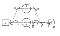
Die dargestellte Vorrichtung zur kontinuierlichen Messung der Masse von Aerosolteilchen in gasförmigen Proben weist eine Strahlungsquelle 1 auf, deren entlang des Strahlenganges 2 abgegebene Strahlung vorerst auf eine planparallele Scheibe 18 trifft, welche für die verwendete Strahlung transparent ist und deren Oberfläche im Brewster-Winkel a p gegen den auftreffenden Strahl geneigt liegt, wodurch ein Strahlteiler geschaffen ist, der auf einfache Weise senkrecht zueinander polarisierte Teilstrahlen liefert. Aufgrund der physikalischen Gesetzmäßigkeiten bei einer derartig angeordneten Scheibe wird von der einfallenden unpolarisierten (d. h. der n-polarisierte Anteil hat ebenso wie der dazu senkrechtstehende p-polarisierte Anteil noch volle 100% Intensität) Strahlung ein n-polarisierter Teilstrahl in Richtung zu einem Spiegel 19 reflektiert ; die p-polarisierten Anteile gehen voll durch die Scheibe 18 in Richtung zum Vergleichsvolumen 9 durch. Der Brewster-Winkel ist dabei wie folgt definiert :![]()
![]()
Der im Brewster-Winkel reflektierte n-polarisierte Teilstrahl passiert nach der Ablenkung am Spiegel 19, der natürlich selbst keine polarisierenden Eigenschaften aufweisen darf, das Prüfvorumen 6 im Meßraum 7 und wird an einem weiteren Spiegel 19 zu einer zweiten, im Strahlengang des p-polarisierten, das Vergleichsvolumen 9 im Meßraum 10 passierenden Teilstrahl angeordneten Scheibe 18 abgelenkt.The n-polarized partial beam reflected at the Brewster angle, after deflection at the
Auch diese zweite Scheibe 18 ist wiederum im Brewster-Winkel α p gegen die Teilstrahlen gerichtet, was wiederum eine Reflexion der n-polarisierten Anteile und ein Durchgehen der p-polarisierten Anteile ergibt. Die nach der zweiten Scheibe 18 wieder vereinigten Teilstrahlen sind der Deutlichkeit halber nebeneinanderliegend eingetragen.This
Vor einem Detektor 20 ist ein rotierender Polarisationsanalysator 21 angeordnet, der je nach seiner Drehstellung nur die entsprechend polarisierten Teile der vereinigten Teilstrahlen durchläßt, welche somit in zeitlicher Aufeinanderfolge am Detektor 20 registriert werden. Am Ausgang 22 des Detektors 20 wird ein Wechselsignal erhalten, das in der Periode der des Analysators 21 entspricht und dessen Größe der Differenz in der Intensität der Teilstrahlen gleicht. Sinnvollerweise wird über einen Abschwächer 23 die relative Intensität der beiden Teilstrahlen zueinander so eingestellt, daß bei partikelfreiem Prüfvolumen 6 am Detektor Signaldifferenz 0 festgestellt wird.A rotating polarization analyzer 21 is arranged in front of a
Bekannte Infrarotquellen und Detektoren zeigen unter Umständen Schwankungen ihrer Intensität bzw. Empfindlichkeit, welche bei längeren Meßzyklen das Ergebnis verfälschen können. Eine Möglichkeit dies zu verhindern besteht beispielsweise dann, mit Hilfe einer genormten Absorberscheibe die Anordnung kontinuierlich zu kalibrieren. Dazu wird auf hier nicht dargestellte Weise mit einer Periode, welche ein ganzzahliges Vielfaches R der Periode des Analysators 21 ist, ein Absorber definierter Absorption ins Prüf- oder Vergleichsvolumen eingebracht. Aus der Differenz der Meßwerte mit bzw. ohne den definierten Absorber erhält man das momentan gültige Produkt aus Quellintensität mal Detektorempfindlichkeit, mit dem der Meßwert ohne Absorber Kalibriert werden kann. Durch diese Anordnung wird zwar die zeitliche Auflösung der Vorrichtung um einen Faktor R schlechter, die Meßgenauigkeit jedoch wesentlich erhöht.Known infrared sources and detectors may show fluctuations in their intensity or sensitivity, which can falsify the result during longer measurement cycles. One way to prevent this is, for example, to continuously calibrate the arrangement using a standardized absorber disk. For this purpose, an absorber of defined absorption is introduced into the test or comparison volume in a manner not shown here with a period which is an integer multiple R of the period of the analyzer 21. From the difference between the measured values with or without the defined absorber, the currently valid product of source intensity times detector sensitivity is obtained, with which the measured value can be calibrated without an absorber. With this arrangement, the temporal resolution of the device is worse by a factor R, but the measuring accuracy is significantly increased.
Anstelle der dargestellten Anordnung zur Polarisation der beiden Teilstrahlen wäre natürlich auch die Verwendung von üblichen Polarisatoren im Strahlengang möglich, was aber kostspieliger ist und die gesamte Einrichtung nicht unwesentlich verteuert.Instead of the arrangement shown for polarizing the two partial beams, it would of course also be possible to use conventional polarizers in the beam path, but this is more expensive and the entire device is not insignificantly more expensive.
Zur Durchführung einer entsprechenden Messung kann beispielsweise das Prüfvolumen 6 unmittelbar vom Auspuffgas einer zu testenden Brennkraftmaschine durchströmt werden, von dem es gilt, die Masse an absorbierenden Aerosolteilchen zu messen. Im Vergleichsvolumen 9 kann sich zu diesem Zwecke Raumluft oder ein ähnliches reines Gasgemisch befinden.To carry out a corresponding Measurement, for example, the
Die die Meßräume 7, 10 passierenden beiden Teilstrahlen werden entsprechend den jeweiligen Absorptionseigenschaften der im Prüfvolumen 6 bzw. Vergleichsvolumen 9 befindlichen Gase bzw. gasförmigen Proben abgeschwächt, wobei bei geeigneter Auswahl der Strahlungsparameter das vom Detektor erhaltene Differenzsignal unmittelbar der Massenbeladung des im Prüfvolumen 6 befindlichen Auspuffgases entspricht. So kann mit einer Strahlungsquelle 1, deren abgegebene Strahlung eine Wellenlänge im Bereich von 3,8 bis 4,15 J.Lm aufweist, mit Hilfe der dargestellten Anordnung nach entsprechender Justierung unmittelbar die in der Probe enthaltene spezifische Masse an breitbandig absorbierenden, insbesonders graphitischen Teilchen bestimmt werden. Es sei hier darauf hingewiesen, daß es für das Funktionieren der erfindungsgemäßen Anordnung prinzipiell keinen Unterschied macht, ob eine schmalbandige Lichtquelle verwendet wird oder die gewünschte Frequenz entweder im Strahlengang 2 oder nach Durchgang durch die Prüf- und Vergleichsvolumina von Filtern selektiert wird. Soferne zusätzlich zur Messung im genannten Frequenzband (3,8 bis 4,15 µm) entweder in zeitlicher Aufeinanderfolge oder in einer zweiten Empfängereinheit auch die Resonanzabsorption bei einer Wellenlänge im Bereich von 3,35 bis 3,5 µm gemessen wird, kann mit einer solchen Anordnung die getrennte Bestimmung von graphitischen und nicht graphitischen bzw. organisch löslichen Anteilen an Aerosolteilchen durchgeführt werden, was für die Bestimmung des Einflusses der Änderung verschiedener Motorenparameter insbesonders in der Entwicklung neuer Motoren bzw. Verbrennungsverfahren sehr wichtig ist.The two partial beams passing through the
Claims (5)
Applications Claiming Priority (2)
| Application Number | Priority Date | Filing Date | Title |
|---|---|---|---|
| AT1788/82 | 1982-05-06 | ||
| AT0178882A AT376301B (en) | 1982-05-06 | 1982-05-06 | METHOD FOR CONTINUOUSLY MEASURING THE MASS OF AEOROSOL PARTICLES IN GASEOUS SAMPLES, AND APPARATUS FOR CARRYING OUT THE METHOD |
Publications (2)
| Publication Number | Publication Date |
|---|---|
| EP0094374A1 EP0094374A1 (en) | 1983-11-16 |
| EP0094374B1 true EP0094374B1 (en) | 1986-07-30 |
Family
ID=3520989
Family Applications (1)
| Application Number | Title | Priority Date | Filing Date |
|---|---|---|---|
| EP83890072A Expired EP0094374B1 (en) | 1982-05-06 | 1983-05-03 | Method for the continuous measurement of the mass of aerosol particles in gaseous samples, and device for carrying out the method |
Country Status (5)
| Country | Link |
|---|---|
| US (1) | US4525627A (en) |
| EP (1) | EP0094374B1 (en) |
| JP (1) | JPS58204340A (en) |
| AT (1) | AT376301B (en) |
| DE (1) | DE3316170A1 (en) |
Families Citing this family (35)
| Publication number | Priority date | Publication date | Assignee | Title |
|---|---|---|---|---|
| AT379452B (en) * | 1983-04-21 | 1986-01-10 | Avl Verbrennungskraft Messtech | METHOD FOR DETERMINING THE SIZES OF ABSORBENT PROPORTIONS OF A SAMPLE, AND DEVICE FOR IMPLEMENTING THE METHOD |
| AT383676B (en) * | 1985-04-04 | 1987-08-10 | Avl Verbrennungskraft Messtech | METHOD FOR PERIODICALLY DETERMINING A MEASURED SIZE AND DEVICE FOR CARRYING OUT THIS METHOD |
| AU573436B2 (en) * | 1985-04-11 | 1988-06-09 | Nippon Steel Corporation | Electromagnetic measurement of particle sizes |
| DE3526458A1 (en) * | 1985-07-24 | 1987-01-29 | Grundig Emv | DEVICE FOR OPTICAL TURBIDITY MEASUREMENT OF GASES |
| DE3539667A1 (en) * | 1985-11-08 | 1987-05-14 | Bruker Analytische Messtechnik | OPTICAL SPECTROMETER, IN PARTICULAR INFRARED SPECTROMETER |
| AT391208B (en) * | 1985-12-09 | 1990-09-10 | Avl Verbrennungskraft Messtech | METHOD FOR THE QUANTITATIVE MEASUREMENT OF HYDROCARBONS |
| JPS63311146A (en) * | 1987-06-13 | 1988-12-19 | Horiba Ltd | Gas analyzer |
| CH673534A5 (en) * | 1987-10-19 | 1990-03-15 | Tecan Ag | |
| AT393325B (en) * | 1988-05-17 | 1991-09-25 | Avl Verbrennungskraft Messtech | METHOD FOR MEASURING THE LAMBDA AND / OR AIR / FUEL RATIO AND DEVICE FOR IMPLEMENTING THE METHOD |
| US5381010A (en) * | 1993-12-03 | 1995-01-10 | Sleepair Corporation | Periodically alternating path and alternating wavelength bridges for quantitative and ultrasensitive measurement of vapor concentration |
| GB2300257B (en) * | 1995-04-28 | 1999-08-25 | Deutsche Forsch Luft Raumfahrt | Method and device for determination of the albedo of particles |
| DE19610439C2 (en) * | 1995-04-28 | 1998-11-26 | Deutsch Zentr Luft & Raumfahrt | Method and device for determining the albedo of an arbitrarily shaped particle |
| US5977546A (en) * | 1997-05-13 | 1999-11-02 | Carlson; Lee Richard | Self normalizing radiant energy monitor and apparatus for gain independent material quantity measurements |
| GB9814701D0 (en) * | 1998-07-08 | 1998-09-02 | Avs Metrology Limited | Radiation monitoring of a physical propert of a material |
| WO2000046584A2 (en) * | 1999-02-02 | 2000-08-10 | Rupprecht & Patashnick Company, Inc. | Differential particulate mass monitor with intrinsic correction for volatilization losses |
| US6205842B1 (en) | 1999-02-02 | 2001-03-27 | Rupprecht & Patashnick Company, Inc. | Differential particulate mass monitor with intrinsic correction for volatilization losses |
| US6502450B1 (en) | 1999-05-10 | 2003-01-07 | Rupprecht & Patashnik Company, Inc. | Single detector differential particulate mass monitor with intrinsic correction for volatilization losses |
| AT409039B (en) * | 1999-11-26 | 2002-05-27 | Avl List Gmbh | METHOD FOR MEASURING OPACITY IN GASES |
| JP2004257909A (en) * | 2003-02-27 | 2004-09-16 | Horiba Ltd | Grain size distribution measuring device |
| JP4014596B2 (en) * | 2004-12-03 | 2007-11-28 | 紀本電子工業株式会社 | Airborne particulate matter measurement device |
| US7505150B2 (en) * | 2005-05-13 | 2009-03-17 | Laytec Gmbh | Device and method for the measurement of the curvature of a surface |
| GB2426579B (en) * | 2005-05-28 | 2008-01-16 | Schlumberger Holdings | Devices and methods for quantification of liquids in gas-condensate wells |
| US8436296B2 (en) * | 2009-11-06 | 2013-05-07 | Precision Energy Services, Inc. | Filter wheel assembly for downhole spectroscopy |
| US8735803B2 (en) * | 2009-11-06 | 2014-05-27 | Precision Energy Services, Inc | Multi-channel detector assembly for downhole spectroscopy |
| EP2615269B1 (en) * | 2012-01-13 | 2014-08-13 | Schaller Automation Industrielle Automationstechnik GmbH & Co. KG | Device and method for determining the parameters of gases and/or an aerosol for a work machine |
| EA026528B1 (en) * | 2014-07-01 | 2017-04-28 | Белорусский Государственный Университет (Бгу) | Method for determining mass concentration of an aerosol |
| US20170084426A1 (en) * | 2015-09-23 | 2017-03-23 | Lam Research Corporation | Apparatus for determining process rate |
| US9735069B2 (en) | 2015-09-23 | 2017-08-15 | Lam Research Corporation | Method and apparatus for determining process rate |
| GB201603051D0 (en) * | 2016-02-23 | 2016-04-06 | Ge Healthcare Bio Sciences Ab | A method and a measuring device for measuring the absorbance of a substance in at least one solution |
| US10784174B2 (en) | 2017-10-13 | 2020-09-22 | Lam Research Corporation | Method and apparatus for determining etch process parameters |
| RU2674560C1 (en) * | 2017-12-28 | 2018-12-11 | Евгений Сергеевич Зубко | Atmosphere optical characteristics measuring method |
| CN112630108A (en) * | 2019-09-24 | 2021-04-09 | 法雷奥汽车空调湖北有限公司 | Particulate matter sensor and vehicle air conditioner assembly |
| EP4053535A1 (en) * | 2021-03-01 | 2022-09-07 | Q.ant GmbH | Particle sensor, device and method for detecting particles |
| DE102022123349A1 (en) | 2022-09-13 | 2024-03-14 | Q.ant GmbH | Particle sensor and method for detecting particles |
| CN116519137B (en) * | 2023-07-04 | 2023-09-15 | 中国科学院合肥物质科学研究院 | Cooperative polarized type device and method for measuring ambient light background radiation |
Family Cites Families (14)
| Publication number | Priority date | Publication date | Assignee | Title |
|---|---|---|---|---|
| US2500213A (en) * | 1945-03-28 | 1950-03-14 | Socony Vacuum Oil Co Inc | Geochemical exploration method by infrared analysis of soil extract solutions |
| US3390605A (en) * | 1963-10-23 | 1968-07-02 | Yanagimoto Seisakusho Co Ltd | Device for measuring simultaneously both rotatory polarization and light absorption |
| FR2097471A5 (en) * | 1970-07-08 | 1972-03-03 | Bazelaire Eric De | |
| US3696247A (en) * | 1970-11-12 | 1972-10-03 | Lionel D Mcintosh | Vehicle exhaust emissions analyzer |
| US3790797A (en) * | 1971-09-07 | 1974-02-05 | S Sternberg | Method and system for the infrared analysis of gases |
| US3805074A (en) * | 1973-01-02 | 1974-04-16 | Texas Instruments Inc | Spectral scan air monitor |
| FI51637C (en) * | 1974-02-22 | 1977-02-10 | Innotec Oy | Symmetrical analyzer with respect to the sample channel and the reference channel. |
| CH569972A5 (en) * | 1974-07-16 | 1975-11-28 | Cerberus Ag | |
| SE7513901L (en) * | 1974-12-19 | 1976-06-21 | United Technologies Corp | VEHICLE EXHAUST SYSTEM ANALYSIS. |
| US3973848A (en) * | 1974-12-19 | 1976-08-10 | United Technologies Corporation | Automatic gas analysis and purging system |
| US4207469A (en) * | 1975-08-02 | 1980-06-10 | Sir Howard Grubb Parsons and Company Ltd. | Analysis of emulsions and suspensions |
| DE2721909A1 (en) * | 1977-05-14 | 1978-11-23 | Philips Patentverwaltung | Standardising arrangement for twin beam photometer - deflects reference beam to measuring photocell for initial arrangement and includes shutter to interrupt either beam |
| DK151393C (en) * | 1978-12-06 | 1988-05-16 | Foss Electric As N | PROCEDURE FOR QUANTITATIVE DETERMINATION OF FAT IN A WATER FAT EMULSION |
| US4229653A (en) * | 1979-03-30 | 1980-10-21 | Sri International | Method and apparatus for monitoring particulate mass concentration of emissions from stationary sources |
-
1982
- 1982-05-06 AT AT0178882A patent/AT376301B/en not_active IP Right Cessation
-
1983
- 1983-05-03 EP EP83890072A patent/EP0094374B1/en not_active Expired
- 1983-05-04 US US06/491,553 patent/US4525627A/en not_active Expired - Lifetime
- 1983-05-04 DE DE3316170A patent/DE3316170A1/en active Granted
- 1983-05-06 JP JP58079993A patent/JPS58204340A/en active Granted
Non-Patent Citations (1)
| Title |
|---|
| Aerosol Science and Technology 1: 225-234, (1982) * |
Also Published As
| Publication number | Publication date |
|---|---|
| AT376301B (en) | 1984-11-12 |
| JPS58204340A (en) | 1983-11-29 |
| JPH0231820B2 (en) | 1990-07-17 |
| DE3316170A1 (en) | 1983-11-17 |
| EP0094374A1 (en) | 1983-11-16 |
| US4525627A (en) | 1985-06-25 |
| DE3316170C2 (en) | 1987-04-30 |
| ATA178882A (en) | 1984-03-15 |
Similar Documents
| Publication | Publication Date | Title |
|---|---|---|
| EP0094374B1 (en) | Method for the continuous measurement of the mass of aerosol particles in gaseous samples, and device for carrying out the method | |
| EP0034156B1 (en) | Process and device for determining glucose in serum or urine | |
| EP0226569B1 (en) | Method for the quantitative measurement of hydrocarbons | |
| DE10240204B3 (en) | Method for the optical measurement of black carbon in the atmosphere and device for carrying out the method | |
| WO2006002740A1 (en) | Non-dispersive infrared gas analyzer | |
| EP1183523B1 (en) | Analysis apparatus | |
| DE3240559C2 (en) | Process for the continuous measurement of the mass of aerosol particles in gaseous samples and device for carrying out the process | |
| DE10392663T5 (en) | A photo-acoustic detection method for measuring the concentration of non-hydrocarbon components of a methane-containing gas mixture | |
| DE102009046279A1 (en) | Measuring device for measuring exhaust gas | |
| DE19509822C2 (en) | Oil concentration measuring device | |
| DE3030002A1 (en) | NON-DISPERSIVE INFRARED GAS ANALYZER | |
| DE3938142C2 (en) | ||
| DE3116344C2 (en) | ||
| WO1999009391A2 (en) | Photometer with non-dispersive infrared absorption spectroscopy (ndir) for measuring several constituents | |
| DE2744168C3 (en) | Magneto-optical spectrophotometer | |
| AT515495B1 (en) | Method and device for determining a particle concentration of a sample gas charged with particles | |
| EP0123672A2 (en) | Method for the determination of the mass of absorbing parts in a sample, and device for carrying out said method | |
| DE19819192C1 (en) | Gas mixture analyzer determining oxygen and a further component, simultaneously, accurately, independently and compactly | |
| DE19741123C2 (en) | Method for the quantitative determination of soot in a soot sample and device for carrying out the method | |
| DE19735599A1 (en) | Nondispersive infrared spectrometer | |
| DE102009058394B3 (en) | Method for measuring the concentration of at least one gas component in a sample gas | |
| DE4025789A1 (en) | Ascertaining particle content in gases and liquids - registering light dispersion in bridging zone between Rayleigh and Mie dispersion | |
| DE102010050549A1 (en) | Method for detecting water in aviation fuel by Raman scattering, involves irradiating aviation fuel with light source, and detecting light, which is scattered by aviation fuel | |
| DE4337227C2 (en) | Two methods for the detection of absorbing substances in solutions and a device for the measurement of linear and saturation signals | |
| DE4130586A1 (en) | Determining particle size concentrations in airborne dust - measuring different contributions of refraction, diffraction and reflection in very narrow forward scattering angle in near infrared |
Legal Events
| Date | Code | Title | Description |
|---|---|---|---|
| PUAI | Public reference made under article 153(3) epc to a published international application that has entered the european phase |
Free format text: ORIGINAL CODE: 0009012 |
|
| AK | Designated contracting states |
Designated state(s): FR GB IT SE |
|
| ITCL | It: translation for ep claims filed |
Representative=s name: MODIANO & ASSOCIATI S.R.L. |
|
| 17P | Request for examination filed |
Effective date: 19831201 |
|
| EL | Fr: translation of claims filed | ||
| GRAA | (expected) grant |
Free format text: ORIGINAL CODE: 0009210 |
|
| AK | Designated contracting states |
Kind code of ref document: B1 Designated state(s): FR GB IT SE |
|
| ITF | It: translation for a ep patent filed |
Owner name: MODIANO & ASSOCIATI S.R.L. |
|
| ET | Fr: translation filed | ||
| PLBE | No opposition filed within time limit |
Free format text: ORIGINAL CODE: 0009261 |
|
| STAA | Information on the status of an ep patent application or granted ep patent |
Free format text: STATUS: NO OPPOSITION FILED WITHIN TIME LIMIT |
|
| 26N | No opposition filed | ||
| ITTA | It: last paid annual fee | ||
| PGFP | Annual fee paid to national office [announced via postgrant information from national office to epo] |
Ref country code: GB Payment date: 19940428 Year of fee payment: 12 |
|
| PGFP | Annual fee paid to national office [announced via postgrant information from national office to epo] |
Ref country code: SE Payment date: 19940530 Year of fee payment: 12 Ref country code: FR Payment date: 19940530 Year of fee payment: 12 |
|
| EAL | Se: european patent in force in sweden |
Ref document number: 83890072.8 |
|
| PG25 | Lapsed in a contracting state [announced via postgrant information from national office to epo] |
Ref country code: GB Effective date: 19950503 |
|
| PG25 | Lapsed in a contracting state [announced via postgrant information from national office to epo] |
Ref country code: SE Effective date: 19950504 |
|
| GBPC | Gb: european patent ceased through non-payment of renewal fee |
Effective date: 19950503 |
|
| EUG | Se: european patent has lapsed |
Ref document number: 83890072.8 |
|
| PG25 | Lapsed in a contracting state [announced via postgrant information from national office to epo] |
Ref country code: FR Effective date: 19960229 |
|
| REG | Reference to a national code |
Ref country code: FR Ref legal event code: ST |
|
| REG | Reference to a national code |
Ref country code: FR Ref legal event code: ST |